

Page 1

Keysight M8132A 640 GSa/s
Digital Signal Processor
User's Guide
Page 2

Notices
CAUTION
WARNING
© Keysight Technologies 2020
No part of this manual may be reproduced
in any form or by any means (including
electronic storage and retrieval or
translation into a foreign language) without
prior agreement and written consent from
Keysight Technologies as governed by
United States and international copyright
laws.
Trademarks
PCI Express® and PCIe® are registered
trademarks of PCI-SIG.
Manual Part Number
M8132-91010
Edition
Edition 2.1, October 2020
Keysight Technologies Deutschland GmbH
Herrenberger Strasse 130,
71034 Böblingen, Germany
Technology Licenses
The hardware and/or software described in
this document are furnished under a
license and may be used or copied only in
accordance with the terms of such license.
U.S. Government Rights
The Software is “commercial computer
software,” as defined by Federal Acquisition
Regulation (“FAR”) 2.101. Pursuant to FAR
12.212 and 27.405-3 and Department of
Defense FAR Supplement
(“DFARS”) 227.7202, the U.S. government
acquires commercial computer software
under the same terms by which the
software is customarily provided to the
public. Accordingly, Keysight provides the
Software to U.S. government customers
under its standard commercial license,
which is embodied in its End User License
Agreement (EULA), a copy of which can be
found at http://www.key-
sight.com/find/sweula. The license set
forth in the EULA represents the exclusive
authority by which the U.S. government
may use, modify, distribute, or disclose the
Software. The EULA and the license set
forth therein, does not require or permit,
among other things, that Keysight:
(1) Furnish technical information related to
commercial computer software or
commercial computer software
documentation that is not customarily
provided to the public; or (2) Relinquish to,
or otherwise provide, the government
rights in excess of these rights customarily
provided to the public to use, modify,
reproduce, release, perform, display, or
disclose commercial computer software or
commercial computer software
documentation. No additional government
requirements beyond those set forth in the
EULA shall apply, except to the extent that
those terms, rights, or licenses are
explicitly required from all providers of
commercial computer software pursuant to
the FAR and the DFARS and are set forth
specifically in writing elsewhere in the
EULA. Keysight shall be under no obligation
to update, revise or otherwise modify the
Software. With respect to any technical
data as defined by FAR 2.101, pursuant to
FAR 12.211 and 27.404.2 and DFARS
227.7102, the U.S. government acquires no
greater than Limited Rights as defined in
FAR 27.401 or DFAR 227.7103-5 (c), as
applicable in any technical data.
Warranty
THE MATERIAL CONTAINED IN THIS
DOCUMENT IS PROVIDED "AS IS," AND IS
SUBJECT TO BEING CHANGED, WITHOUT
NOTICE, IN FUTURE EDITIONS. FURTHER,
TO THE MAXIMUM EXTENT PERMITTED BY
APPLICABLE LAW, KEYSIGHT DISCLAIMS
ALL WARRANTIES, EITHER EXPRESS OR
IMPLIED WITH REGARD TO THIS MANUAL
AND ANY INFORMATION CONTAINED
HEREIN, INCLUDING BUT NOT LIMITED TO
THE IMPLIED WARRANTIES OF
MERCHANTABILITY AND FITNESS FOR A
PARTICULAR PURPOSE. KEYSIGHT SHALL
NOT BE LIABLE FOR ERRORS OR FOR
INCIDENTAL OR CONSEQUENTIAL
DAMAGES IN CONNECTION WITH THE
FURNISHING, USE, OR PERFORMANCE OF
THIS DOCUMENT OR ANY INFORMATION
CONTAINED HEREIN. SHOULD KEYSIGHT
AND THE USER HAVE A SEPARATE
WRITTEN AGREEMENT WITH WARRANTY
TERMS COVERING THE MATERIAL IN THIS
DOCUMENT THAT CONFLICT WITH THESE
TERMS, THE WARRANTY TERMS IN THE
SEPARATE AGREEMENT WILL CONTROL.
Safety Notices
A CAUTION notice denotes a hazard.
It calls attention to an operating
procedure, practice, or the like that,
if not correctly performed or adhered
to, could result in damage to the
product or loss of important data.
Do not proceed beyond a CAUTION
notice until the indicated conditions
are fully understood and met.
A WARNING notice denotes a hazard.
It calls attention to an operating
procedure, practice, or the like that,
if not correctly performed or adhered
to, could result in personal injury or
death. Do not proceed beyond a
WARNING notice until the indicated
conditions are fully understood and
met.
2 Keysight M8132A 640 GSa/s Digital Signal Processor User’s Guide
Page 3

Safety Summary
Initial Inspection Inspect the shipping container for damage. If there is damage to the container or
General This product is a Safety Class 3 instrument (provided with a protective earth terminal).
The following general safety precautions must be observed during all phases of operation
of this instrument. Failure to comply with these precautions or with specific warnings or
operating instructions in the product manuals violates safety standards of design,
manufacture, and intended use of the instrument. Keysight Technologies assumes no
liability for the customer's failure to comply with these requirements. Product manuals
are provided with your instrument on CD-ROM and/or in printed form. Printed manuals
are an option for many products. Manuals may also be available on the Web. Go to
www.keysight.com and type in your product number in the Search field at the top of the
page. Safe operation and the general safety precautions for the M9502A and M9505A
AXIe chassis, must be followed. See: http://www.keysight.com/find/M9505A.
cushioning, keep them until you have checked the contents of the shipment for
completeness and verified the instrument both mechanically and electrically. The
Performance Tests give procedures for checking the operation of the instrument. If the
contents are incomplete, mechanical damage or defect is apparent, or if an instrument
does not pass the operator’s checks, notify the nearest Keysight Technologies
Sales/Service Office.
WARNING To avoid hazardous electrical shock, do not perform electrical tests when
there are signs of shipping damage to any portion of the outer enclosure (covers, panels,
etc.).
The protective features of this product may be impaired if it is used in a manner not
specified in the operation instructions.
Laser Safety Information Class 1 Laser product according IEC60825-1 (2007).
Environment Conditions
Before Applying Power
This instrument is intended for indoor use in an installation category II, pollution degree 2
environment. It is designed to operate within a temperature range of 0 °C – 40 °C
(32 °F – 105 °F) at a maximum relative humidity of 80% and at altitudes of up to
2000 meters.
This module can be stored or shipped at temperatures between -40 °C and +70 °C.
Protect the module from temperature extremes that may cause condensation within it.
Verify that all safety precautions are taken. The power cable inlet of the instrument serves
as a device to disconnect from the mains in case of hazard. The instrument must be
positioned so that the operator can easily access the power cable inlet. When the
instrument is rack mounted the rack must be provided with an easily accessible mains
switch.
Line Power Requirements The Keysight M8132A operates when installed in an Keysight AXIe mainframe.
Keysight M8132A 640 GSa/s Digital Signal Processor User’s Guide 3
Page 4

Do Not Operate in an
Explosive Atmosphere
Do not operate the instrument in the presence of flammable gases or fumes.
Do Not Remove the
Instrument Cover
Ground the Instrument
Operating personnel must not remove instrument covers. Component replacement and
internal adjustments must be made only by qualified personnel.
Instruments that appear damaged or defective should be made inoperative and secured
against unintended operation until they can be repaired by qualified service personnel.
To minimize shock hazard, the instrument chassis and cover must be connected to an
electrical protective earth ground. The instrument must be connected to the ac power
mains through a grounded power cable, with the ground wire firmly connected to an
electrical ground (safety ground) at the power outlet. Any interruption of the protective
(grounding) conductor or disconnection of the protective earth terminal will cause a
potential shock hazard that could result in personal injury.
4 Keysight M8132A 640 GSa/s Digital Signal Processor User’s Guide
Page 5
Instrument Markings
The Tab le 1 lists the definitions of markings that may be on or with the product.
Table 1 Instrument Markings
Marking Description
The instruction documentation symbol. The product is marked with this symbol
when it is necessary for the user to refer to the instruction in the documentation.
Frame or chassis ground terminal. Typically connects to the equipment’s metal
frame.
KC is the Korean certification mark to demonstrate that the equipment is Class A
suitable for professional use and is for use in electromagnetic environments outside
of the home.
Indicates that anti-static precautions should be taken.
China Restricted Substance Product Label. The EPUP (environmental protection use
period) number in the center indicates the time period during which no hazardous
or toxic substances or elements are expected to leak or deteriorate during normal
use and generally reflects the expected useful life of the product.
The RCM mark is a registered trademark of the Australian Communications and
Media Authority.
The CSA mark is a registered trademark of the CSA International.
Keysight M8132A 640 GSa/s Digital Signal Processor User’s Guide 5
Page 6

Marking Description
The CE mark is a registered trademark of the European Community (if accompanied
by a year, it is the year when the design was proven). This product complies with all
relevant directives.
Universal recycling symbol. This symbol indicates compliance with the China
standard GB 18455-2001 as required by the China RoHS regulations for
paper/fiberboard packaging.
The Keysight email address is required by EU directives applicable to our product.
6 Keysight M8132A 640 GSa/s Digital Signal Processor User’s Guide
Page 7

Compliance and Environmental Information
Table 2 Compliance and Environmental Information
Safety Symbol Description
This product complies with WEEE Directive (2002/96/EC) marking requirements.
The affixed label indicates that you must not discard this electrical/electronic
product in domestic household waste.
Product Category: With reference to the equipment types in WEEE Directive Annex I,
this product is classed as a “Monitoring and Control instrumentation” product.
Do not dispose in domestic household waste.
To return unwanted products, contact your local Keysight office, or see
http://about.keysight.com/en/companyinfo/environment/takeback.shtml for more
information.
Keysight M8132A 640 GSa/s Digital Signal Processor User’s Guide 7
Page 8

Page 9

Contents
1 Introduction
2 Software Installation
3 Soft Front Panel
Safety Summary 3
Instrument Markings 5
Compliance and Environmental Information 7
M8132A Overview 17
Key Features 17
Instrument Options 18
Front Panel 18
Related Documents 20
Additional Documents 20
Launching the Soft Front Panel 24
Command Line Arguments 27
Communication 28
Soft Front Panel 30
Title Bar 31
Menu Bar 31
Lower Pane 33
Errors List Window 34
Status Bar 35
Clock Tab 36
IOs Tab 37
Keysight M8132A 640 GSa/s Digital Signal Processor User’s Guide 9
Page 10

Contents
IOs Tab in 10GbE mode 40
Cabling for 10GbE Connectivity 48
System Monitor Tab 49
4 Control In/Out
Control In/Out and Trigger Input 52
Input Multiplexer of the Switch Matrix 53
Output Multiplexer of the Switch Matrix 54
Trigger Input 55
5 Using KF 9000A PathWave FPGA with the M8132A
6 Remote Programming
Remote Programming Overview 60
Instructions 60
Instruction Header 60
White Space (Separator) 60
Braces 61
Ellipsis 61
Square Brackets 61
Program Data 61
Status Commands 62
STATus:PRESet 64
Status Byte Register 64
Questionable Data Register Command Subsystem 65
Reference Clock Status Subsystem 66
Connection Status Subsystem 66
Latency Calibration Commands 68
:CALibrate:LATency:LCMPeriod 68
:CALibrate:LATency:MODE 68
:CALibrate:LATency[:STEP] 69
:CALibrate:LATency:SPDelay 69
10 Keysight M8132A 640 GSa/s Digital Signal Processor User’s Guide
Page 11

Common Commands 70
*IDN? 70
*CLS 70
*ESE 70
ESR? 70
*OPC 70
*OPC? 71
*OPT? 71
*RST 71
*SRE[?] 71
*STB? 71
*TST? 71
*LRN? 72
*WAI? 72
System Commands 73
:SYSTem:ERRor[:NEXT]? 73
:SYSTem:HELP:HEADers? 73
:SYSTem:LICense:EXTended:LIST? 74
:SYSTem:SET[?] 74
:SYSTem:VERSion? 75
:SYSTem:COMMunicate:*? 75
:SYSTem:COMMunicate:INSTr[:NUMBer]? 75
:SYSTem:COMMunicate:HISLip[:NUMBer]? 76
:SYSTem:COMMunicate:SOCKet[:PORT]? 76
:SYSTem:COMMunicate:TELNet[:PORT]? 76
:SYSTem:COMMunicate:TCPip:CONTrol? 76
:SYSTem:ERRor:COUNt? 77
:SYSTem:LICense:LIST? 77
:SYSTem:LICense:SUBScription:DATE? 77
Contents
Time Base Commands 78
:TIMebase:REFClock 78
Keysight M8132A 640 GSa/s Digital Signal Processor User’s Guide 11
Page 12

Contents
Instrument Commands 79
:INSTrument:SLOT[:NUMBer]? 79
:INSTrument:IDENtify 79
:INSTrument:IDENtify:STOP 79
:INSTrument:HWRevision? 79
FPGA Access Commands 80
:INSTrument:FPGA:UPDate 80
:INSTrument:FPGA:RESet 80
:INSTrument:FPGA:DIRect:DWORd[?] 81
:INSTrument:FPGA:DIRect:BLOCk[?] 81
:INSTrument:FPGA:GEARbox:CLEar 82
:INSTrument:FPGA:GEARbox:STARt 82
Current and Power Monitor Commands 83
:INSTrument:MONitor:CURRent[:TOTal]? 83
:INSTrument:MONitor:CURRent:MGTAVCC? 83
:INSTrument:MONitor:CURRent:MGTAVTT? 83
:INSTrument:MONitor:CURRent:VCCINT? 84
:INSTrument:MONitor:POWer[:TOTal]? 84
:INSTrument:MONitor:POWer:MGTAVCC? 84
:INSTrument:MONitor:POWer:MGTAVTT? 85
:INSTrument:MONitor:POWer:VCCINT? 85
12 Keysight M8132A 640 GSa/s Digital Signal Processor User’s Guide
Page 13

Sandbox Commands 86
:INSTrument:SANDbox<M>:NAME? 86
:INSTrument:SANDbox<M>:FNAMe? 86
:INSTrument:SANDbox<M>:FVERsion? 86
:INSTrument:SANDbox<M>:KID? 87
:INSTrument:SANDbox<M>:SID? 87
:INSTrument:SANDbox<M>:CONFigure 87
:INSTrument:SANDbox<M>:RLISt? 88
:INSTrument:SANDbox<M>:RINFo? 88
:INSTrument:SANDbox<M>:PEEK? 88
:INSTrument:SANDbox<M>:POKE 89
:INSTrument:SANDbox<M>:SREad? 89
:INSTrument:SANDbox<M>:SREad:BLOCk? 89
:INSTrument:SANDbox<M>:SWRite 90
:INSTrument:SANDbox<M>:SWRite:BLOCk 90
:INSTrument:SANDbox<M>:MLISt? 90
:INSTrument:SANDbox<M>:MINFo? 91
:INSTrument:SANDbox<M>:MREad? 91
:INSTrument:SANDbox<M>:MREad:BLOCk? 91
:INSTrument:SANDbox<M>:MWRite 92
:INSTrument:SANDbox<M>:MWRite:BLOCk 92
Contents
Keysight M8132A 640 GSa/s Digital Signal Processor User’s Guide 13
Page 14

Contents
Optical Data Interface Commands 93
:ODI:ACHannels? 93
:ODI:PORT:COUNt? 93
:ODI:PORT<N>:CAPability:DIRection? 94
:ODI:PORT<N>:CAPability:FCONtrols? 94
:ODI:PORT<N>:CAPability:LANes? 94
:ODI:PORT<N>:CAPability:NAME? 95
:ODI:PORT<N>:CAPability:RATes? 95
:ODI:PORT<N>:CAPability:RBMax? 95
:ODI:PORT<N>:CAPability:TBMax? 95
:ODI:PORT<N>:CAPability:TRMatch? 96
:ODI:PORT<N>:NAME? 96
:ODI:PORT<N>:ACTivate 96
:ODI:PORT<N>:DEACtivate 97
:ODI:PORT<N>:CSTatus? 97
:ODI:PORT<N>:PSTatistics:BBURsts? 100
:ODI:PORT<N>:PSTatistics:RBYTes? 100
:ODI:PORT<N>:PSTatistics:TBYTes? 100
:ODI:PORT<N>:PSTatistics:THOFfs? 100
Trigger Commands 101
:TRIGger:OUTPut:MODE 101
:TRIGger:OUTPut:SOURce 102
:TRIGger:LEVel:EXTernal 102
Control In/Out Commands 103
:CIOut:MUX 103
:CIOut:MUX:CLR 105
:CIOut:OUTPut 105
TEST Commands 106
:TEST:PON? 106
:TEST:TST? 106
14 Keysight M8132A 640 GSa/s Digital Signal Processor User’s Guide
Page 15

7 Examples
Contents
Ethernet Commands 107
:ETHernet:PORT[1-8]:[STATe][?] 107
:ETHernet:PORT[1-8]:FRAMe:MACSource:[STAte][?] 107
:ETHernet:PORT[1-8]:FRAMe:MACSource:VALue[?] 108
:ETHernet:PORT[1-8]:FRAMe:MACDest:[STAte][?] 108
:ETHernet:PORT[1-8]:FRAMe:MACDest:VALue [?] 109
:ETHernet:PORT[1-8]:FRAMe:ETHertype:[STAte][?] 109
:ETHernet:PORT[1-8]:FRAMe:ETHertype:VALue[?] 110
:ETHernet:PORT[1-8]:CSTatus? 110
:ETHernet:PORT[1-8]:PSTatistics[:RX]:GOOD? 111
:ETHernet:PORT[1-8]:PSTatistics[:RX]:BAD? 111
:ETHernet:PORT[1-8]:PSTatistics[:RX]:DROPped? 111
:ETHernet:PORT[1-8]:PSTatistics[:RX]:BYTes? 112
:ETHernet:PORT[1-8]:PSTatistics:TX:BYTes? 112
:ETHernet:PORT[1-8]:PSTatistics:ALL? 112
Introduction 114
PathwaveCapture 115
Cabling of DSP Connectors 115
Setup DSP 115
Usage 115
PathwaveLoopThrough 116
Cabling of DSP Connectors 116
Usage 116
Optional Parameters 117
SimpleRspExample 118
Cabling of DSP Connectors 118
Setup DSP 118
Usage 118
Keysight M8132A 640 GSa/s Digital Signal Processor User’s Guide 15
Page 16

Contents
PathwaveDpu2Dpu 119
Cabling of DSP Connectors 119
Setup DSP 119
Usage 119
PathwaveEthernet 120
Cabling of DSP Connectors 120
Setup DSP 120
Usage 120
Continuous Streaming with Deterministic Latency to DSP
Module 121
8 Characteristics
Performance Specification 123
Operating Environment 123
General 124
Index
16 Keysight M8132A 640 GSa/s Digital Signal Processor User’s Guide
Page 17

Keysight M8132A 640 GSa/s Digital Signal Processor
User’s Guide
1 Introduction
M8132A Overview / 17
Key Features / 17
Front Panel / 18
Related Documents / 20
Additional Documents / 20
This chapter provides an overview of M8132A 640 GSa/s Digital Signal
Processor module.
M8132A Overview
The Keysight M8132A is a 640 GSa/s Digital Signal Processor.
Key Features
The M8132A Digital Signal Processor provides the following key features:
• Two large Xilinx Ultrascale+ VU9P FPGAs usable for custom processing
functions
• 4 x 160 Gb/s bidirectional optical data interfaces (ODI) or 3x 160Gbits/s
input/output and 8 * 10Gbe Ethernet
• Aggregate throughput 640 Gb/s input + 640 Gb/s output
• PCIe backplane interface up to Gen3 x8
• Part of Keysight’s Wideband Solution Platform (WSP)
• Deterministic latency between Digitizer (M8131A), DSP module
(M8132A) and AWG (M8121A)
• 2-slot AXIe module
Page 18
1 Introduction
Instrument Options
The M8132A can be ordered as M8132A-002. The -002 indicates that two
Xilinx Ultrascale+ VU9P FPGAs are available.
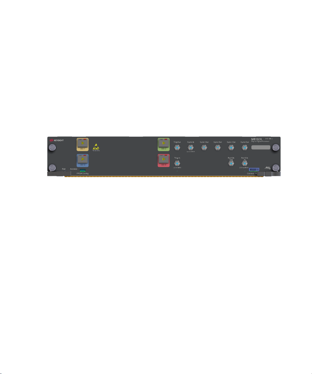
Front Panel
Figure 1 on page 18 illustrates the front panel of the M8132A instrument.
Figure 1 M8132A front panel
The M8132A front panel includes the following input/output ports:
Inputs/Outputs
• ODI - The four Optical Data Interface ports (ODI 1/2/3/4) can be used
for optical data streaming. ODI 4 can be used for 8*10Gbe Ethernet.
• Trig In - The Trigger Input can be used for external triggering. As
Trigger source e.g. an external pulse generator can be connected. The
FPGA designer has access to the “Trigger Input” signal inside both
FPGA and may implement desired functionality.
• Trig Out - The Trigger Output can be used to trigger external
instruments or DUTs. The FPGA designer can control the “Trigger
Output” signal inside both FPGA and may implement desired
functionality.
• Sync In - The Sync Input can be used to synchronize the M8132A DSP
module with an M8131A digitizer module in order to achieve a
deterministic latency between the M8131A and the M8132A. Sync In
of the M8132A is connected to the Sync Out of the M8131A digitizer
module.
18 Keysight M8132A 640 GSa/s Digital Signal Processor User’s Guide
Page 19

LEDs
Introduction 1
• Sync Out - The four Sync Outputs can be used to synchronize the
M8132A with one or more M8121A AWG modules in order to achieve
deterministic latency between the M8132A and the M8121A AWG.
Sync Out of the M8132A is connected to the Sync In of the M8121A
AWG module.
• Ref Clk In - The Reference Clock Input can be used to synchronize to an
external clock.
• Ref Clk Out - The Reference Clock Output can be used to synchronize a
DUT to the M8132A.
• FPGA Config - The FPGA Configuration connector can be used to
debug open FPGA externally.
• Control In/Out - The Control Input/Output offers a 10-bit parallel
interface. Bit 0 to 4 is configured as input, bit 5 to 9 is configured as
output. The Control In/Out is connected with the sandbox ports of the
FPGAs.
The M8132A front panel include the following LEDs:
•Status LEDs
The “Fail” and “Access” LEDs are available at the front panel to indicate
the status of the M8132A module:
• The green ‘Access’ LED indicates that the controlling PC exchanges
data with the M8132A module.
• The red ‘Fail’ LED has following functionality:
• It is ‘ON’ for about 30 seconds after powering the AXIe chassis.
• After about 30 seconds the LED is switched ‘OFF’. If an external
PC is used to control the AXIe chassis, this PC can be powered
after this LED has switched OFF.
• During normal operation of the module this LED is ‘OFF’. In
case of an error condition such as e.g. a self-test error, the LED
is switch ‘ON’.
• In case the output relay has shut-off because of an external
overload condition, this LED flashes.
Keysight M8132A 640 GSa/s Digital Signal Processor User’s Guide 19
Page 20

1 Introduction
• Trig In LED - This LED indicates that an externally applied signal
matches the adjusted threshold to be used as a Trigger. The LED turns
on for ~100 ms for each detected edge of the correct polarity. I.e. a
rising edge turns the LED on for 100 ms if the polarity is adjusted to
rising. If the polarity is adjusted to rising and a falling edge is externally
applied, the LED remains OFF. The functionality of this LED is for future
use and is currently not supported.
• Ref Clk In LED - This LED is green when a valid signal at Ref Clk In is
detected. In case of invalid signals, it is red. The functionality of this
LED is for future use and is currently not supported.
Related Documents
To access documentation related to the Keysight M8132A Digital Signal
Processor, use one of the following methods:
• CD - Browse the product CD for M8132A documentation.
• Start > All Programs > Keysight M8131 > Keysight M8131
Documentation - Provides links to all product documentation except
for the IVI driver documentation.
• Start > All Programs > Keysight Instrument Drivers > KtM8131
Digitizer - Provides link to the product IVI driver help system.
• Go to the product web site (www.keysight.com/find/M8132A) and
browse the manuals under Document Library tab.
Additional Documents
Additional documentation can be found at:
• http://www.keysight.com/find/M9502A for 2-slot chassis related
documentation.
• http://www.keysight.com/find/M9505A for 5-slot chassis related
documentation.
• http://www.keysight.com/find/M9506A for 5-slot chassis related
documentation.
• http://www.keysight.com/find/M9514A for 14-slot chassis related
documentation.
• http://www.keysight.com/find/M9537A for embedded AXIe controller
related documentation.
• http://www.keysight.com/products/KF9000A for KF9000A PathWave
FPGA related documentation.
20 Keysight M8132A 640 GSa/s Digital Signal Processor User’s Guide
Page 21

Keysight M8132A 640 GSa/s Digital Signal Processor
User’s Guide
2 Software Installation
The M8132A Digital Signal Processor package is installed along with the
M8131A Digitizer package, using the same installer. Therefore, all
prerequisites and installation procedure for M8132A module is the same
as that for M8131A. For more information, refer to the M8131A User
Guide.
http://www.keysight.com/find/M8131A
Page 22

Page 23

Keysight M8132A 640 GSa/s Digital Signal Processor
User’s Guide
3 Soft Front Panel
Launching the Soft Front Panel / 24
Command Line Arguments / 27
Communication / 28
Soft Front Panel / 30
Clock Tab / 36
IOs Tab / 37
IOs Tab in 10GbE mode / 40
System Monitor Tab / 49
This chapter describes the M8132A Soft Front Panel.
Page 24
3 Soft Front Panel
Launching the Soft Front Panel
There are two ways to launch the M8132A Soft Front Panel:
1 Select Start > All Programs > Keysight M8131 > Keysight M8131 Soft
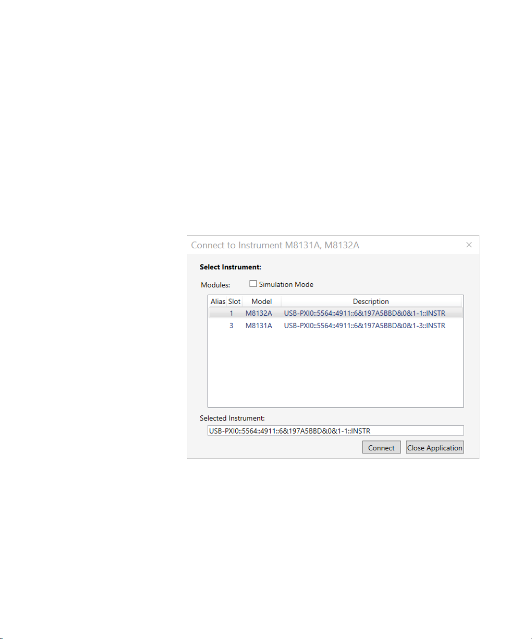
2From the Keysight Connection Expert select the discovered M8132
The following Connect to Instrument dialog will appear:
Front Panel from the Start menu.
module, select the “Installed Software” tab and press the “Soft Front
Panel” icon. Please note that only instruments connected via PCIe are
shown in the Keysight Connection Expert.
Figure 2 M8132A connected to PC
This dialog shows the addresses of the discovered M8132A modules.
Select a module from the list and press “Connect”.
24 Keysight M8132A 640 GSa/s Digital Signal Processor User’s Guide
Page 25
Soft Front Panel 3
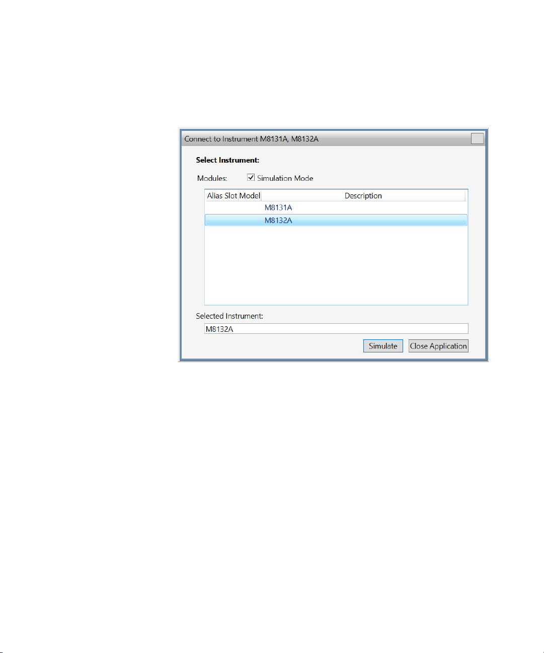
If no M8132A module is connected to your PC, you can select “Simulation
Mode” to simulate an M8132A module.
Figure 3 M8132A in simulation mode
Next, a software startup screen will be displayed as shown in
Figure 4 on page 26.
Keysight M8132A 640 GSa/s Digital Signal Processor User’s Guide 25
Page 26
3 Soft Front Panel
Figure 4 M8132A startup screen
26 Keysight M8132A 640 GSa/s Digital Signal Processor User’s Guide
Page 27

Command Line Arguments
Option Description
/Socket socketPort Set the socket port at which the Soft Front Panel waits for SCPI commands.
/Telnet telnetPort Set the telnet port at which the Soft Front Panel waits for SCPI commands.
Soft Front Panel 3
(See Communication on page 28 for details about /Socket, /Telnet, /Inst,
/HiSLIP, /AutoID, /NoAutoID, /FallBack).
Table 3 Command line arguments
/Inst instrumentNumber Set the instrument number (instN, hislipN) at which the Soft Front Panel waits for SCPI commands on
VXI-11.3 and HiSLIP connections (if not specified with /HiSLIP).
/HiSLIP hislipNumber Set the instrument number for HiSLIP SCPI communication. If not specified, the same number as for
VXI-11.3 is used.
/AutoID Automatically select ports and numbers for the connections (default behavior).
/NoAutoID Disable the default behavior; i.e. do not automatically select ports and numbers for the connections.
/FallBack Try to find unused ports and number if starting a server fails.
/NoSplash Don't show the splash screen.
/Minimized Start with the SFP window minimized to the Windows task bar.
/Title “title” Additional information shown in the SFP window title.
/OutputDir Set the output directory for the log file and temporary files.
/r resourceName Visa PXI resource string of the module to connect to, e.g. PXI12::0::0::INSTR. “auto” selects the next free
instrument.
/M8132TenGbe Starts up the M8132A with three ODI ports and eight 10 GbE ports instead of the usual four ODI ports.
Keysight M8132A 640 GSa/s Digital Signal Processor User’s Guide 27
Page 28

3 Soft Front Panel
Communication
Depending on the command line arguments /Socket, /Telnet, /Inst,
/AutoID, /NoAutoID, /FallBack, the Soft Front Panel starts several servers
to handle SCPI commands. (Refer to the table above.)
/Socket, /Telnet, /Inst, /HiSLIP: If -1, do not start the respective servers
Defaults:
• Socket port: 5025 (e.g. TCPIP0::localhost::5025::SOCKET)
• Telnet port: 5024
• HiSLIP: 0 (e.g. TCPIP0::localhost::hislip0::INSTR)
• VXI-11.3: 0 (e.g. TCPIP0::localhost::inst0::INSTR)
/FallBack: If starting a server fails because of a conflict, try using another
port or number
• HiSLIP, VXI-11.3: increase the index until a server can be started
successfully
• Socket, Telnet: start with port 60000, then increase it until the servers
can be started successfully. If neither socket nor telnet is disabled, the
Soft Front Panel tries to start the servers on two consecutive ports
(socket port = telnet port + 1)
/AutoID: Automatically select ports and number for the connections,
which are unique per instrument.
This is the default behavior; it is not necessary to specify this argument on
the command line.
If only one AXIe module is connected to this PC and it is an M8132A
module, first try to use the command line arguments /Socket, /Telnet,
/Inst, or their respective default values if they are not specified. If starting
the servers fails, proceed with the steps below.
/Socket, /Telnet, /Inst, /HiSLIP are ignored (unless they are -1 and a
server is disabled)
If the Soft Front Panel detects more than one AXIe module, use a special
mechanism to obtain a number for the HiSLIP and VXI-11.3 servers, which
makes sure that the Soft Front Panel uses always the same VISA resource
string per module
The socket and telnet port are then calculated from the HiSLIP index:
• telnet port = 60000 + 2 * <HiSLIP index>
• socket port = 60000 + 2 * <HiSLIP index> + 1
28 Keysight M8132A 640 GSa/s Digital Signal Processor User’s Guide
Page 29

Soft Front Panel 3
NOTE
NOTE
Ports may already be in use by Windows or other applications, so they
are not available for M8132A.
/NoAutoID: Do not automatically select ports and number for the
connections, use the values specified with /Socket, /Telnet, /Inst, /HiSLIP
or their respective default values instead.
If both /NoAutoID and /AutoID are specified, /AutoID overrides /NoAutoID.
The first port not assigned by IANA is 49152 (IANA, Internet Assigned
Numbers Authority,
http://www.iana.org)
Keysight M8132A 640 GSa/s Digital Signal Processor User’s Guide 29
Page 30
3 Soft Front Panel
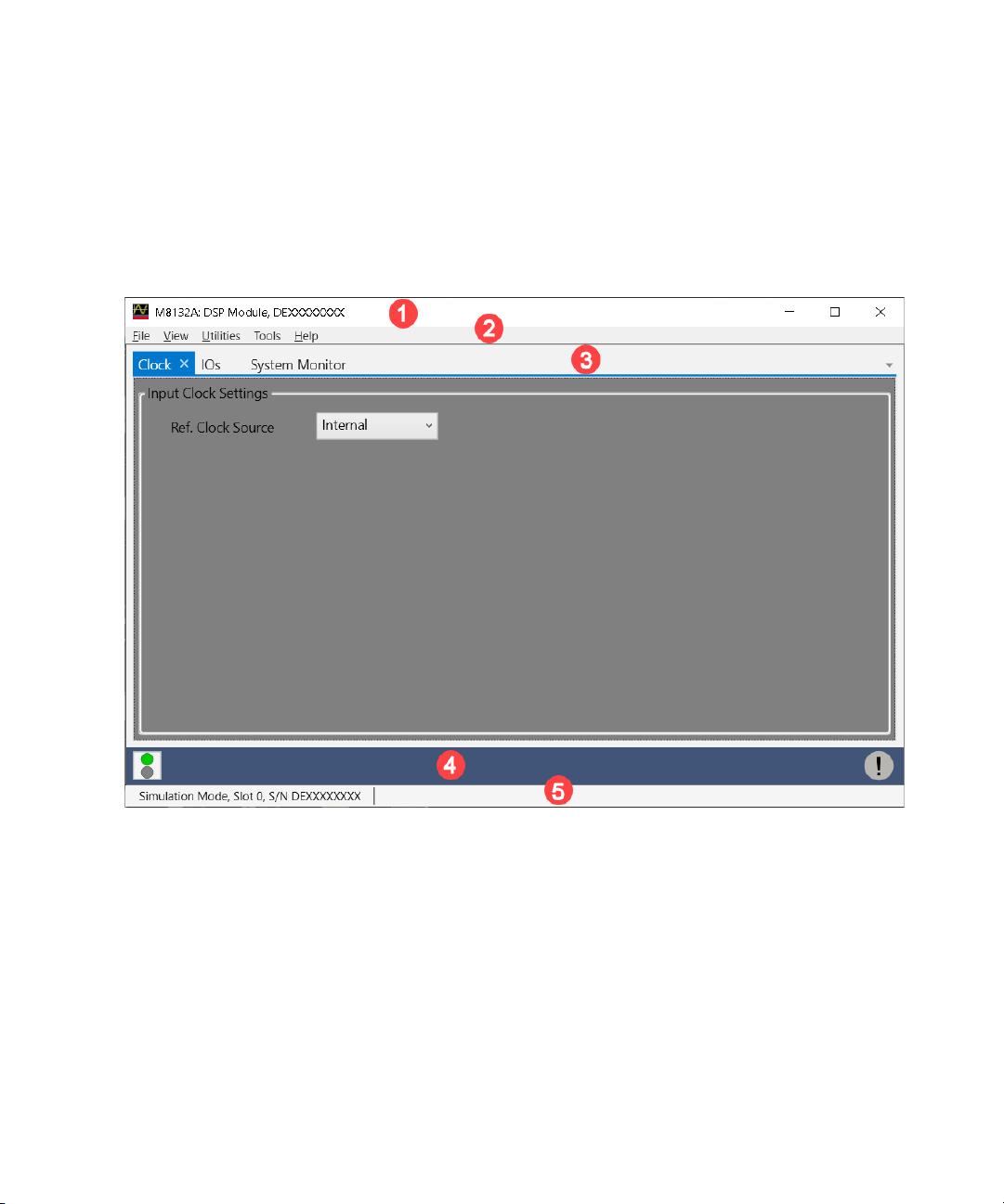
Soft Front Panel
The Soft Front Panel and its elements are illustrated in the following
figure:
Figure 5 M8132A user interface
The Soft Front Panel includes the following elements:
1Title Bar
2 Menu Bar
3 Tabs (Clock, IOs and System Monitor)
4Lower Pane
5 Status Bar
The detailed information on these GUI elements are described in the
sections that follow.
30 Keysight M8132A 640 GSa/s Digital Signal Processor User’s Guide
Page 31

Title Bar
Menu Bar
File Menu
Soft Front Panel 3
The title bar contains the standard Microsoft Windows elements such as
the window title and the icons for minimizing, maximizing, or closing the
window.
The menu bar consists of various pull-down menus that provide access to
the different functions and launch interactive GUI tools.
The menu bar includes the following pull-down menus:
•File
•View
• Utilities
•Tools
•Help
Each menu and its options are described below.
The File menu includes the following selections:
File > Connect… Opens the “Connect to Instrument” dialog. See Launching the Soft
Front Panel on page 24.
File > Save Configuration As… Saves configuration as a text file. This feature is not implemented in the
File > Load Configuration… Loads the previously saved configuration file. This feature is not implemented
File > Exit Exits the M8132A application.
Keysight M8132A 640 GSa/s Digital Signal Processor User’s Guide 31
current software release.
in the current software release.
Page 32

3 Soft Front Panel
View Menu
The View menu includes the following selections:
View > Hide Minimizes the GUI to notify icon.
Utilities Menu
The Utilities menu includes the following selections:
Utility > Identify Identifies the instrument by flashing the green “Access” LED on the front
Utility > Reset Resets the instrument, reads the state and updates all fields.
Utility > Self Test… Opens a window to start the self-test and display the result after completion.
Tools Menu
panel for a certain time.
Not functional in the current software release.
The Tools menu includes the following selections:
Tools > Clock Switch to the “Clock” tab on Parameters window if it is already open. If not, it
Tools > IOs Switch to the “IOs” tab on Parameters window if it is already open. If not, it
Tools > System Monitor Switch to the “System Monitor” tab on Parameters window if it is already
adds “Clock” tab first. For details, see Clock Tab on page 36.
adds “IOs” tab first. For details, see IOs Tab on page 37.
open. If not, it adds “System Monitor” tab first. For details, see System
Monitor Tab
on page 49.
32 Keysight M8132A 640 GSa/s Digital Signal Processor User’s Guide
Page 33

Help Menu
The Help menu includes the following selections:
Help > User Guide Opens the M8132A User’s Guide.
Help > Examples Opens the Examples directory.
Help > Online Support Opens the instrument’s product support web page.
Soft Front Panel 3
Help > About Displays product information including version number, build date, build
info, installed licenses, available options and web links for M8132A
information and support.
Lower Pane
The lower pane provides the following options:
Show Status Window Opens the Status Window. This feature is currently not implemented.
Show Error List Window Opens the window that shows the list of errors and warnings. For details, see
Errors List Window on page 34
Keysight M8132A 640 GSa/s Digital Signal Processor User’s Guide 33
Page 34

3 Soft Front Panel
Errors List Window
Use this window to view errors, warnings, and information.
Figure 6 Error list window
For each error, it shows error details i.e. notification type, time stamp and
description.
It has the following controls, signs, and columns:
(Clear All) Click this button to clear all the errors from the errors list
Open On Error Click this toggle button to automatically open the errors list
Copy Click this button to copy the selected message(s).
Select All Click this button to select all messages inside the list.
34 Keysight M8132A 640 GSa/s Digital Signal Processor User’s Guide
window.
window whenever an error occurs (default) or not.
Page 35

Status Bar
Soft Front Panel 3
The status bar contains the following fields from left to right:
• Connection state:
• “Not Connected” – No instrument is connected.
• “Connected: <Instrument resource string>” – An instrument is
connected. The resource string, for example PXI36::0::0::INSTR is
displayed.
• “Simulation Mode” – No real instrument is connected. The user
interface is in simulation mode. Click this field to open the
Instrument Selection Dialog.
• Instrument status - Displays the instrument status, for example “Reset
complete” after issuing a reset command.
Keysight M8132A 640 GSa/s Digital Signal Processor User’s Guide 35
Page 36

3 Soft Front Panel
Clock Tab
The Clock tab provides the clock settings to M8132A module.
Figure 7 Clock tab
Input Clock Settings
• Ref. Clock Source - A clock reference input is provided on the front
panel of the M8132A module. The options are:
• Internal
• External 100MHz
36 Keysight M8132A 640 GSa/s Digital Signal Processor User’s Guide
Page 37

IOs Tab
Soft Front Panel 3
The IOs tab provides input and output settings for optical data interfaces.
Figure 8 IOs tab
Keysight M8132A 640 GSa/s Digital Signal Processor User’s Guide 37
Page 38

3 Soft Front Panel
• Optical Data Interfaces (ODI) - Select an ODI from ODI1, ODI2, ODI3,
or ODI4 to set the respective parameters.
• Enable Port - The respective ODI ports can be activated/deactivated by
selecting this checkbox. An error for loss of signal will be shown, if a
checkbox is asserted without making the physical connections.
• ODI Parameters - The following ODI Parameters are available:
• Transmit Max Burst - This is the maximum burst size.
• Lane Rate - Currently R141 is the only supported lane rate.
• Direction - Select an option.
• Bidirectional
• Producer
• Consumer
• TX Flow Control - Select an option for the transmit flow control.
The following options are available:
• None - No flow control.
• In Band - In-band flow control.
• RX Flow Control - Select an option for the receive flow control.
The following options are available:
• None - No flow control.
• In Band - In-band flow control.
• Statistics - Display the ODI statistics. The following options are
available:
• Status – It is a hexadecimal value that corresponds to a 32-bit
register, which shows the current status of the port. Hover on the
numeric field to open the tooltip, which provides information about
every bit and its current value.
• Bytes Sent- Number of bytes sent over the ODI link.
• Bytes Received - Number of bytes received over the ODI link.
• Bad Bursts Received - Number of bad bursts received over the ODI
link.
• Tx Flow Holdoffs - The number of ODI clock cycles during which the
transmitter was held off, irrespective of whether there was
something to transmit or not.
• Refresh Statistics: Reset the ODI statistics.
• Control In/Out - For information on Control In/Out, refer to Control
In/Out Commands on page 103.
38 Keysight M8132A 640 GSa/s Digital Signal Processor User’s Guide
Page 39

Soft Front Panel 3
• Selftests - This option tests whether the particular ODI port is
functional or not. Connect a loopback connector to the respective port
and run a self-test. It will test whether the port allows proper
transmission of data. The test reports the connection status, and in
case of failure, the status of each individual lane. All failed test steps
are shown. Possible errors are PLL lock failures, burst, overflow,
underflow, CRC, and alignment errors.
Keysight M8132A 640 GSa/s Digital Signal Processor User’s Guide 39
Page 40

3 Soft Front Panel
IOs Tab in 10GbE mode
When opened through the command line argument /M8132TenGbe, the
M8132A displays three ODI ports and eight 10 GbE ports instead of the
usual four ODI ports. The ODI4 tab is replaced with 10 GbE, and the
Selftest ODI4 button is replaced with Selftest 10 GbE.
40 Keysight M8132A 640 GSa/s Digital Signal Processor User’s Guide
Page 41

• On the IOs tab, click 10GbE tab.
Soft Front Panel 3
Keysight M8132A 640 GSa/s Digital Signal Processor User’s Guide 41
Page 42

3 Soft Front Panel
NOTE
The following options are available in the 10GbE tab.
• 8 * 10 GbE Ports (ODI4) - A panel containing tabs for the 10 GbE ports
is displayed. There are eight available ports. Each 10 GbE port can be
independently controlled using its own tab.
• Enable 10GbE Port 1 - The option enables/disables the 10GbE port.
• LED Color - The LED next to Enable 10GbE Port 1 option displays the
following colors:
• Grey - Not Enabled
• Dark - Enabled, no optical signal detected (LOS)
• Yellow - Enabled, optical signal detected but Receiver Valid Ctrl
Code not detected
• Green - Enabled, Receiver Valid Ctrl Code detected
The LED color is updated approximately once per second.
The LED behavior is more consistent between 10 GbE and ODI when
there is LOS (Loss of Optical Signal).
• 10GbE Parameters - These parameters can be used to set selected
fields in transmitted Ethernet Frames. As changing the fields controlled
by the Override parameters may cause networking problems, access to
these parameters is protected by a checkbox and warning tooltip.
Advanced Setting Tooltip: All of the 10 GbE parameters display the same
tooltip (when enabled). The tooltip disappears after 5s.
42 Keysight M8132A 640 GSa/s Digital Signal Processor User’s Guide
Page 43

Soft Front Panel 3
NOTE
The following parameters cannot be changed when the port is
enabled.
• Modify Advanced Parameters - It allows modification of the
Override settings (Source MAC, Dest MAC, and EtherType).
When “Modify Advanced Parameters” is checked, you can access
the override settings.
When “Modify Advanced Parameters” is unchecked, override
settings cannot be changed (greyed out). This is the default view.
The “Modify Advanced Parameters” checkbox cannot be modified while
the 10 GbE port is enabled.
• Override Source MAC - When checked, the source MAC address
field in each transmitted packet will use the parameter value. When
unchecked, the source MAC address field is transmitted unchanged
from the CAA design.
Parameter Value: Hexadecimal formatted 48 bit source MAC
address.
Reset: A unique locally-administered value created from the
instrument serial number and ethernet port number of form
82:09:02:xx:xx:xx
Keysight M8132A 640 GSa/s Digital Signal Processor User’s Guide 43
Page 44

3 Soft Front Panel
• Override Dest MAC - When checked, the destination MAC address
field in each transmitted packet will use the parameter value. When
unchecked, the destination MAC address field is transmitted
unchanged from the CAA design.
Parameter Value: Hexadecimal formatted 48 bit destination MAC
address
Reset: 00:00:00:00:00:00
• Override EtherType - When checked, the EtherType in each
transmitted packet will use the parameter value. When unchecked,
the EtherType field is transmitted unchanged from the CAA design.
Parameter Value: Hexadecimal formatted two octet EtherType
Reset: 0x800
• Statistics - This section of the panel displays the current 10 GbE port
statistics. The statistics are updated approximately once per second.For
all results apart from Status, there are two columns:
• Results - Displays the cumulative total result count since the last
time the Port was enabled (or the Reset Statistics button was
pressed)
• Rate (/s) - Displays the rate calculated over approximately the last
one second.
The following Statistics are available:
• Status - Displays the status of the port. Status bits are latched
between the approximately once per second screen updates. All bits
are reset when the port is enabled. A value of 0 is expected during
error-free normal operation.
Bit0: Optical LOS
Bit1: !STAT_RX_VALID_CTRL_CODE
Bit2: !STAT_RX_BLOCK_LOCK_REG
Bit3: Unused
Bit4: STAT_RX_HI_BER
Bit5: STAT_RX_REMOTE_FAULT
Bit6: STAT_RX_LOCAL_FAULT
Bit7: STAT_RX_INTERNAL_LOCAL_FAULT
Bit8: STAT_RX_RECEIVED_LOCAL_FAULT
Bit9: STAT_RX_BAD_PREAMBLE"
44 Keysight M8132A 640 GSa/s Digital Signal Processor User’s Guide
Page 45

Soft Front Panel 3
NOTE
Bit10: STAT_RX_BAD_SFD
Bit11: STAT_RX_GOT_SIGNAL_OS
Bit12: STAT_TX_LOCAL_FAULT
Bit13: STAT_TX_FRAMING_ERROR
Bits 14-15: Unused
Bit16: STAT_TXUNFOUT
The Status tooltip decodes the current status value and is on a timer, so
it disappears after 15s. The names are cryptic but should match names in
Xilinx documentation.
• Bytes Sent - The result displays the number of transmitted bytes.
The byte count is reset to 0 when the port is enabled, or the Reset
Statistics button is pressed. Rate displays the number of bytes per
second transmitted over the previous second.
• Bytes Received - The result displays the number of received bytes.
The byte count is reset to 0 when the port is enabled, or the Reset
Statistics button is pressed. Rate displays the number of bytes per
second received over the previous second.
Keysight M8132A 640 GSa/s Digital Signal Processor User’s Guide 45
Page 46

3 Soft Front Panel
• Rx Good Frames - The result displays the number of received good
frames (packets). The packet-count is reset to 0 when the port is
enabled, or the Reset Statistics button is pressed. Rate displays the
number of good frames per second received over the previous
second.
• Rx Bad Frames - The result displays the number of received bad
frames (packets). The packet-count is reset to 0 when the port is
enabled, or the Reset Statistics button is pressed. (Bad packets are
calculated as the difference between total packets and good
packets) Rate displays the number of bad frames per second
received over the previous second.
• Rx Dropped Frames - The result displays the number of received
dropped packets. The packet-count is reset to 0 when the port is
enabled, or the Reset Statistics button is pressed. (Dropped packets
are calculated as the sum of undersize, oversize and packets with
bad FCS) Rate displays the number of dropped frames per second
received over the previous second.
• Reset Statistics - Resets the port statistics to 0. It does not reset
port operation.
• Selftest 10 GbE - It enables all eight ports and checks that an optical
signal is received on each port and that each receiver detects the Valid
Ctrl Code. This action affects all eight ports, not only the currently
selected port. When button is pressed, a popup appears:
If all parts of the test pass, then “Passed” is displayed.
46 Keysight M8132A 640 GSa/s Digital Signal Processor User’s Guide
Page 47

Soft Front Panel 3
If any part of the test fails, then all pass / fail results are shown.
Keysight M8132A 640 GSa/s Digital Signal Processor User’s Guide 47
Page 48

3 Soft Front Panel
Cabling for 10GbE Connectivity
When Ethernet operation is selected, Port 4 needs to use a special
breakout cable (M8132A-830) that fans out the MTP/MPO connector to 8
LC Tx/Rx pairs to connect to SFP+ 10GBe optical connections. The link
uses OM3 multimode cable and is compatible with 10GBASE-SR physical
layer requirements of IEEE 802.3.
For information on 10GbE, refer to: IEEE 802.3 standards.
48 Keysight M8132A 640 GSa/s Digital Signal Processor User’s Guide
Page 49

System Monitor Tab
Soft Front Panel 3
Power Measurement
The M8132 is designed to supply 2 FPGAs within a total of 75W max per
FPGA (VCCINT + MGTAVCC + MGTAVTT). In general, the module is
protected against overcurrent and overtemperature. To ensure that the
operation remains within limits, the user can measure the power
consumption of the FPGAs in the System Monitor Tab. Such a query is
recommended every time a new custom FPGA is loaded in the module, but
before the query, the FPGAs should be configured in a mode that
consumes the maximum power.
For more information about the queries via SCPI command, refer to
Remote Programming on page 59.
Figure 9 System Monitor tab
Keysight M8132A 640 GSa/s Digital Signal Processor User’s Guide 49
Page 50

Page 51

Keysight M8132A 640 GSa/s Digital Signal Processor
User’s Guide
4 Control In/Out
Control In/Out and Trigger Input / 52
This chapter describes the Control In/Out and Trigger Input.
Page 52

4 Control In / Out
Control In/Out and Trigger Input
The interfaces of the sandboxes in the FPGA designs generated by
PathWave FPGA contain the general-purpose pins GP_TRIG_IN (0..2) as
input ports and GP_TRIG_OUT (0..2) as output ports.
The front panel input ports “Control In/Out (0..4)” and the trigger input
“Trig In” can be routed to GP_TRIG_IN(0..2) and the output ports “Control
In/Out (5..9)” can be sourced by GP_TRIG_OUT (0..2) of each FPGA.
The following picture shows the switch matrix that allows to configure the
connections between the front panel and the sandbox ports:
52 Keysight M8132A 640 GSa/s Digital Signal Processor User’s Guide
Page 53

The Control In/Out (0..9) port is separated in 5 inputs (Control In (0..4)) and
5 outputs (Control Out (5..9)). Each multiplexer has a separate clear
mechanism that sets all outputs of the corresponding multiplexer to zero.
Additionally, it is possible to disable the output ports of Control Out (5..9).
This sets the ports to “high impedance”.
All input sources for each multiplexer can be routed to each output. The
switch matrix is clocked with a 200 MHz clock, and therefore all inputs are
synchronized to this clock. After input synchronization, the transmission is
cycle accurate.
Example: When routing the Control In (0) to both FPGAs, the connected
signal is synchronized to the 200 MHz clock. So, there is an input accuracy
of 5ns. Once synchronized to this clock, the transmission is cycle accurate,
which means that the connected signal information will arrive at the
sandbox port of both FPGAs at the same time.
The LOOP_BACK (1..0) connection allows to transfer of information
between the two FPGA sandboxes synchronously.
Input Multiplexer of the Switch Matrix
Four bits are used to select the source for each output of the input
multiplexer. The corresponding bit positions inside the selector field in the
soft front panel are specified in the following table.
Control In / Out 4
Table 4 Bit Positions for Output Ports of the Input Multiplexer of the Switch Matrix
Bit Positions Output Port
23..20 GP_TRIG_IN_B(2)
19..16 GP_TRIG_IN_B(1)
15..12 GP_TRIG_IN_B(0)
11..8 GP_TRIG_IN_A(2)
7..4 GP_TRIG_IN_A(1)
3..0 GP_TRIG_IN_A(0)
Keysight M8132A 640 GSa/s Digital Signal Processor User’s Guide 53
Page 54

4 Control In / Out
The corresponding input ports are coded as shown in the following table:
Table 5 Coding of Input Ports of the Input Multiplexer of the Switch Matrix:
Value (binary) Port
0000 Control In (0)
0001 Control In (1)
0010 Control In (2)
0011 Control In (3)
0100 Control In (4)
0101 Trig In
0110 Reserved, do not use
0111 Reserved, do not use
1000 LOOP_BACK (0)
1001 LOOP_BACK (1)
Output Multiplexer of the Switch Matrix
Three bits are used to select the source for each output of the output
multiplexer. The corresponding bit positions inside the selector field in the
soft front panel are specified in the following table.
Table 6 Bit Positions for Output Ports of the Output Multiplexer of the Switch Matrix
Bit Positions Output Port
20..18 LOOP_BACK (1)
17..15 LOOP_BACK (0)
14..12 Control Out (9)
11..9 Control Out (8)
8..6 Control Out (7)
5..3 Control Out (6)
2..0 Control Out (5)
54 Keysight M8132A 640 GSa/s Digital Signal Processor User’s Guide
Page 55

Trigger Input
Control In / Out 4
The corresponding input ports are coded as shown in the following table:
Table 7 Coding of Input Ports of the Output Multiplexer of the Switch Matrix
Value (binary) Port
000 GP_TRIG_OUT_A(0)
001 GP_TRIG_OUT_A(1)
010 GP_TRIG_OUT_A(2)
011 GP_TRIG_OUT_B(0)
100 GP_TRIG_OUT_B(1)
101 GP_TRIG_OUT_B(2)
The trigger input (Trig In) is connected to a trigger generator that
produces a trigger pulse on each rising edge of the connected input signal.
The trigger threshold can be set via remote programming interface (SCPI).
For more details on trigger specification, refer to the datasheet of the
instrument.
Keysight M8132A 640 GSa/s Digital Signal Processor User’s Guide 55
Page 56

Page 57

Keysight M8132A 640 GSa/s Digital Signal Processor
User’s Guide
5 Using KF 9000A
PathWave FPGA with
the M8132A
PathWave FPGA KF9000A must be used as the design tool to program the
sand boxes of the Xilinx FPGA inside the M8132A.
Additional documentation can be found at:
• http://www.keysight.com/products/KF9000A for KF9000A PathWave
FPGA related documentation.
• http://www.keysight.com/find/M8132A for M8132A BSP (RSP and
FSP) related documentation.
Page 58

Page 59

Keysight M8132A 640 GSa/s Digital Signal Processor
User’s Guide
6 Remote Programming
Remote Programming Overview / 60
Status Commands / 62
Latency Calibration Commands / 68
Common Commands / 70
System Commands / 73
Time Base Commands / 78
Instrument Commands / 79
FPGA Access Commands / 80
Current and Power Monitor Commands / 83
Sandbox Commands / 86
Optical Data Interface Commands / 93
Trigger Commands / 101
Control In/Out Commands / 103
TEST Commands / 106
Ethernet Commands / 107
Page 60

6 Remote Programming
Remote Programming Overview
This chapter introduces the basics for remote programming of an M8132A
instrument using SCPI commands.
Instructions
Instructions, both commands and queries, normally appear as strings
embedded in a statement of your host language, such as Visual Basic for
Applications (VBA), Visual Basic .NET, C#, C, etc.
The only time a parameter is not meant to be expressed as a string is when
the instruction's syntax definition specifies <binary_block _data>, such as
with the :SYSTem:SET command. There are only a few instructions that
use block data.
Instructions are composed of two main parts:
• The header, which specifies the command or query to be sent.
• The program data, which provides additional information to clarify the
meaning of the instruction.
Instruction Header
The instruction header is one or more command mnemonics separated by
colons (:). They represent the operation to be performed by the instrument.
Queries are formed by adding a question mark (?) to the end of the header.
Many instructions can be used as either commands or queries, depending
on whether or not you include the question mark. The command and query
forms of an instruction usually have different program data. Many queries
do not use any program data.
White Space (Separator)
White space is used to separate the instruction header from the program
data. If the instruction does not require any program data parameters, you
do not need to include any white space. In this manual, white space is
defined as one or more spaces. ASCII defines a space to be character 32 in
decimal.
60 Keysight M8132A 640 GSa/s Digital Signal Processor User’s Guide
Page 61

Braces
Ellipsis
Square Brackets
Program Data
Remote Programming 6
When several items are enclosed by braces, { }, only one of these elements
may be selected. Vertical line ( | ) indicates "or". For example, {ON | OFF}
indicates that only ON or OFF may be selected, not both.
... An ellipsis (trailing dots) indicates that the preceding element may be
repeated one or more times.
Items enclosed in square brackets, [ ], are optional.
Program data is used to clarify the meaning of the command or query. It
provides necessary information, such as whether a function should be on
or off, or which waveform is to be displayed. Each instruction's syntax
definition shows the program data and the values they accept.
When there is more than one data parameter, they are separated by
commas (,). You can add spaces around the commas to improve
readability.
Keysight M8132A 640 GSa/s Digital Signal Processor User’s Guide 61
Page 62

6 Remote Programming
Status Commands
This section describes the structure of the SCPI status system used by the
M8132A. The status system records various conditions and states of the
instrument in several register groups as shown on the following pages.
Each of the register groups is made up of several low level registers called
Condition registers, Event registers, and Enable registers which control the
action of specific bits within the register group.
These groups are explained below:
A condition register continuously monitors the state of the instrument. The
bits in the condition register are updated in real time and the bits are not
latched or buffered. This is a read-only register and bits are not cleared
when you read the register. A query of a condition register returns a
decimal value which corresponds to the binary-weighted sum of all bits set
in that register.
An event register latches the various events from changes in the condition
register. There is no buffering in this register; while an event bit is set,
subsequent events corresponding to that bit are ignored. This is a read
only register. Once a bit is set, it remains set until cleared by query
command (such as STAT:QUES:EVEN?) or a *CLS (clear status)
command. A query of this register returns a decimal value which
corresponds to the binary-weighted sum of all bits set in that register.
An enable register defines which bits in the event register will be reported
to the Status Byte register group. You can write to or read from an enable
register. A *CLS (clear status) command will not clear the enable register
but it does clear all bits in the event register. A STAT:PRES command
clears all bits in the enable register. To enable bits in the enable register to
be reported to the Status Byte register, you must write a decimal value
which corresponds to the binary weighted sum of the corresponding bits.
Transition Filters are used to detect changes of the state in the condition
register and set the corresponding bit in the event register. You can set
transition filter bits to detect positive transitions (PTR), negative transitions
(NTR) or both. Transition filters are read/write registers. They are not
affected by *CLS.
62 Keysight M8132A 640 GSa/s Digital Signal Processor User’s Guide
Page 63

0
1
2
3
4
5
6
7
0
1
2
3
4
5
6
7
0
1
2
3
4
5
6
7
8
9
10
11
12
13
14
15
0
1
2
QUEStionable Status
Error/Event Queue
Standard Event
Status Register
Status Byte
Operation Complete
Query Error
Execution Error
Command Error
Power On
MAV
RQS
Summary of IEEE 488.2 Status Structure Registers
0
Reference
Clock
USB Module Connection State
Device Dependent Error
Remote Programming 6
Keysight M8132A 640 GSa/s Digital Signal Processor User’s Guide 63
Figure 10 Status register structure
Page 64

6 Remote Programming
STATus:PRESet
Status Byte Register
Clears all status group event registers. Presets the status group enables
PTR and NTR registers as follows:
ENABle = 0x0000, PTR = 0xffff, NTR = 0x0000
The Status Byte summary register reports conditions from the other status
registers. Data that is waiting in the instrument’s output buffer is
immediately reported on the “Message Available” bit (bit 4) for example.
Clearing an event register from one of the other register groups will clear
the corresponding bits in the Status Byte condition register. Reading all
messages from the output buffer, including any pending queries, will clear
the “Message Available” bit. To set the enable register mask and generate
an SRQ (service request), you must write a decimal value to the register
using the *SRE command.
Table 8 Status byte register
64 Keysight M8132A 640 GSa/s Digital Signal Processor User’s Guide
Bit Number Decimal Value Definition
0 Not used 1 Not Used. Returns “0”
1 Not used 2 Not Used. Returns “0”
2 Error Queue 4 One or more errors are stored in the Error Queue
3 Questionable Data 8 One or more bits are set in the Questionable Data
Register (bits must be enabled)
4 Message Available 16 Data is available in the instrument’s output buffer
5 Standard Event 32 One or more bits are set in the Standard Event Register
6 Master Summary 64 One or more bits are set in the Status Byte Register
7 Operational Data 128 One or more bits set in the Operation Data Register (bits
must be enabled)
Page 65

Questionable Data Register Command Subsystem
The Questionable Data register group provides information about the
quality or integrity of the instrument. Any or all of these conditions can be
reported to the Questionable Data summary bit through the enable
register.
Table 9 Questionable data register
Bit Number Decimal Value Definition
0 Not used 1 Returns “0”
1 Not used 2 Returns “0”
2 Not used 4 Returns “0”
3 Not used 8 Returns “0”
4 Not used 16 Returns “0”
5 Reference Clock Status 32 Instable or missing external reference clock.
6 Not used 64 Returns “0”
Remote Programming 6
7 USB disconnected 128 USB module connection state
8 Not used 256 Returns “0”
9 Not used 512 Returns “0”
10 Not used 1024 Returns “0”
11 Not used 2048 Returns “0”
12 Not used 4096 Returns “0”
13 Not used 8192 Returns “0”
14 Not used 16384 Returns “0”
15 Not used 32768 Returns “0”
Keysight M8132A 640 GSa/s Digital Signal Processor User’s Guide 65
Page 66

6 Remote Programming
Reference Clock Status Subsystem
The Reference Clock Status register contains information about the
validity of the 100 MHz external reference clock of the module
The following SCPI commands and queries are supported:
:STATus:QUEStionable:REFClock[:EVENt]?
:STATus:QUEStionable:REFClock:CONDition?
:STATus:QUEStionable:REFClock:ENABle[?]
:STATus:QUEStionable:REFClock:NTRansition[?]
:STATus:QUEStionable:REFClock:PTRansition[?]
Table 10 Reference clock status register
Bit Number Decimal Value Definition
0 Amplitude too small 1 Amplitude of external reference signal too small or
1 Not used 2 Returns “0”
2 Frequency out-of-range 4 Frequency of external reference signal out-of-range.
no signal.
Connection Status Subsystem
The Connection Status register contains the state of the USB connection
to the M8132A module.
The following SCPI commands and queries are supported:
:STATus:QUEStionable:CONNection[:EVENt]?
:STATus:QUEStionable:CONNection:CONDition?
:STATus:QUEStionable:CONNection:ENABle[?]
:STATus:QUEStionable:CONNection:NTRansition[?]
:STATus:QUEStionable:CONNection:PTRansition[?]
66 Keysight M8132A 640 GSa/s Digital Signal Processor User’s Guide
Page 67

Remote Programming 6
Table 11 Connection status register
Bit Number Decimal Value Definition
0 USB disconnected 1 USB module connection state
Keysight M8132A 640 GSa/s Digital Signal Processor User’s Guide 67
Page 68

6 Remote Programming
Latency Calibration Commands
:CALibrate:LATency:LCMPeriod
Command :CALibrate:LATency:LCMPeriod <lcm_period>
Description This command sets the Least Common Multiple (LCM) period value to be
The Latency Calibration commands are used to initialize the deterministic
latency in the data path between the M8131A digitizer and the DSP. The
digitizer, as the module connected upstream in the data path, will be
referred to as the master in the command description. The DSP, as the
module connected downstream in the data path, will be referred to as the
slave. For deterministic latency initialization, a defined sequence of
commands must be sent to master and slave. For more information, refer
to the example program described in section “Continuous Streaming with
Constant Latency to DSP Module” in the M8131A user guide.
used for core clock phase alignment. On the master module, this value
determines the frequency of the signal sent out at the Sync Out. On the
slave module, this value determines the frequency of the signal used to
compare with the signal received at the Sync In. The formula for the
frequency is:
f = 400MHz / LCM period.
<lcm_period> The LCM period as an even integer between 2 and 32768.
Query :CALibrate:LATency:LCMPeriod?
Description This query returns the current LCM period.
:CALibrate:LATency:MODE
Command :CALibrate:LATency:MODE {SEParate | COMBined}
Description This command selects the latency calibration mode.
• SEParate – Phase alignment to the master’s core clock and latency
calibration are separate steps. This mode is used for latency setup
between M8131A and M8132A DSP.
• COMBined - Phase alignment to the master’s core clock and latency
calibration is done in the same step. This mode is used for the latency
setup between M8131A and M8121A AWG.
68 Keysight M8132A 640 GSa/s Digital Signal Processor User’s Guide
Page 69

Remote Programming 6
:CALibrate:LATency[:STEP]
Command :CALibrate:LATency[:STEP] {GSYNc | ALIGnphase | SSYNc
| ARMadjust | PREPare}
Description This command executes a step in the latency calibration of the data path
between master and slave. As mentioned in brackets, some commands are
sent to and affect only the master and some only the slave module. It is
indicated as well, when commands are relevant only for one calibration
mode (SEParate, COMBined).
• GSYNc - Generate clock signal at Sync Out (master, SEParate).
• ALIGnphase - Use the clock signal received at Sync In to align the
phase of the core clock (slave).
• SSYNc - Stop the clock signal generation at Sync Out (master).
• ARMadjust - Arm the module for latency adjustment (slave). When the
master starts sending data over the ODI, the latency is measured in the
slave, and the FIFOs are adjusted accordingly.
• PREPare - Set the Sync Out to pulse mode (master, SEParate). When
data streaming is started, a single pulse is sent at the Sync Out.
:CALibrate:LATency:SPDelay
Command :CALibrate:LATency:SPDelay {A|B}, <sync_pulse_delay>
Description This command sets the synchronization pulse delay for the selected FPGA
in multiples of the core clock period (5ns).
A Selects FPGA A.
B Selects FPGA B.
<sync_pulse_delay> The synchronization pulse delay as an unsigned
integer between 0 and 1023.
Query :CALibrate:LATency:SPDelay? {A|B}
Description This query returns the synchronization pulse delay for the selected FPGA.
Keysight M8132A 640 GSa/s Digital Signal Processor User’s Guide 69
Page 70

6 Remote Programming
Common Commands
*IDN?
*CLS
Read the instrument’s identification string which contains four fields
separated by commas. The first field is the manufacturer’s name, the
second field is the model number, the third field is the serial number, and
the fourth field is a revision code which contains four numbers separated
by dots and a fifth number separated by a dash:
Keysight Technologies, M8132A,<serial number>,
x.x.x.x-h
x.x.x.x= Soft Front Panel revision number, e.g. 2.0.0.0
h= Hardware revision number
Clear the event register in all register groups. This command also clears
the error queue and cancels a *OPC operation. It doesn’t clear the enable
register.
70 Keysight M8132A 640 GSa/s Digital Signal Processor User’s Guide
*ESE
Enable bits in the Standard Event Status Register to be reported in the
Status Byte. The selected bits are summarized in the “Standard Event” bit
(bit 5) of the Status Byte Register. The *ESE? query returns a value which
corresponds to the binary-weighted sum of all bits enabled decimal by the
*ESE command. These bits are not cleared by a *CLS command. Value
Range: 0–255.
ESR?
Query the Standard Event Status Register. Once a bit is set, it remains set
until cleared by a *CLS (clear status) command or queried by this
command. A query of this register returns a decimal value which
corresponds to the binary-weighted sum of all bits set in the register.
*OPC
Set the “Operation Complete” bit (bit 0) in the Standard Event register
after the previous commands have been completed.
Page 71

*OPC?
*OPT?
*RST
*SRE[?]
Remote Programming 6
Return “1” to the output buffer after the previous commands have been
completed. Other commands cannot be executed until this command
completes.
Read the installed options. The response consists of any number of fields
separated by commas.
Reset instrument to its factory default state.
Enable bits in the Status Byte to generate a Service Request. To enable
specific bits, you must write a decimal value which corresponds to the
binary-weighted sum of the bits in the register. The selected bits are
summarized in the “Master Summary” bit (bit 6) of the Status Byte
Register. If any of the selected bits change from “0” to “1”, a Service
Request signal is generated. The *SRE? query returns a decimal value
which corresponds to the binary-weighted sum of all bits enabled by the
*SRE command.
*STB?
Query the summary (status byte condition) register in this register group.
This command is similar to a Serial Poll but it is processed like any other
instrument command. This command returns the same result as a Serial
Poll but the “Master Summary” bit (bit 6) is not cleared by the *STB?
command.
*TST?
Execute Self Tests. If self-tests pass, a 0 is returned. A number lager than 0
indicates the number of failed tests.
To get actual messages, use :TEST:TST?
Keysight M8132A 640 GSa/s Digital Signal Processor User’s Guide 71
Page 72

6 Remote Programming
*LRN?
*WAI?
Query the instrument and return a binary block of data containing the
current settings (learn string). You can then send the string back to the
instrument to restore this state later. For proper operation, do not modify
the returned string before sending it to the instrument. Use :SYST:SET to
send the learn string. See :SYSTem:SET[?] on page 74.
Prevents the instrument from executing any further commands until the
current command has finished executing.
72 Keysight M8132A 640 GSa/s Digital Signal Processor User’s Guide
Page 73

System Commands
:SYSTem:ERRor[:NEXT]?
Remote Programming 6
Query :SYSTem:ERRor?
Description The query read and clear one error from the instrument’s error queue.
A record of up to 30 command syntax or hardware errors can be stored in
the error queue. Errors are retrieved in first-in-first-out (FIFO) order. The
first error returned is the first error that was stored. Errors are cleared as
you read them.
If more than 30 errors have occurred, the last error stored in the queue
(the most recent error) is replaced with “Queue overflow”. No additional
errors are stored until you remove errors from the queue.
If no errors have occurred when you read the error queue, the instrument
responds with 0,“No error”.
The error queue is cleared by the *CLS command, when the power is
cycled, or when the Soft Front Panel is re-started.
The error queue is not cleared by a reset (*RST) command.
The error messages have the following format (the error string may contain
up to 255 characters):
error number,”Description”, e.g.
-113,”Undefined header”.
Example Query
:SYST:ERR?
:SYSTem:HELP:HEADers?
Query :SYSTem:HELP:HEADers?
Description The query returns all SCPI commands and queries and IEEE 488.2
common commands and common queries implemented by the instrument.
The response is a <DEFINITE LENGTH ARBITRARY BLOCK RESPONSE
DATA> element. The full path for every command and query is returned
separated by linefeeds.
Keysight M8132A 640 GSa/s Digital Signal Processor User’s Guide 73
Page 74

6 Remote Programming
:SYSTem:LICense:EXTended:LIST?
The syntax of the response is defined as: The <nonzero digit> and
sequence of <digit> follow the rules in IEEE 488.2, Section 8.7.9. A <SCPI
header> is defined as: It contains all the nodes from the root. The <SCPI
program mnemonic> contains the node in standard SCPI format. The short
form uses uppercase characters while the additional characters for the
long form are in lowercase characters. Default nodes are surrounded by
square brackets ([]).
Example Query
:SYST:HELP:HEAD?
Query :SYSTem:LICense:EXTended:LIST?
Description The query lists the licenses installed.
Example Query
:SYST:LIC:EXT:LIST?
74 Keysight M8132A 640 GSa/s Digital Signal Processor User’s Guide
:SYSTem:SET[?]
Command :SYSTem:SET[?] <binary block data>
Description In query form, the command reads a block of data containing the
instrument’s complete set-up. The set-up information includes all
parameter and mode settings, but does not include the contents of the
instrument setting memories or the status group registers. The data is in a
binary format, not ASCII, and cannot be edited.
In set form, the block data must be a complete instrument set-up read
using the query form of the command.
This command has the same functionality as the *LRN command.
Parameters <binary block data>
Example Command
:SYST:SET <binary block data>
Query
:SYST:SET?
Page 75

Remote Programming 6
:SYSTem:VERSion?
Command :SYSTem:VERSion?
Description The query returns a formatted numeric value corresponding to the SCPI
version number for which the instrument complies.
Example Query
:SYST:VERS?
:SYSTem:COMMunicate:*?
Command :SYSTem:COMMunicate:*?
Description The query returns information about the instrument Soft Front Panel’s
available connections. If a connection is not available, the returned value
is -1.
This is only useful if there is more than one Keysight module connected to
a PC, otherwise one would normally use the default connections (HiSLIP
and VXI-11 instrument number 0, socket port 5025, telnet port 5024)
One can never be sure if a socket port is already in use, so one could e.g.
specify a HiSLIP number on the command line (AgM8132SFP.exe /AutoID
/Inst5 /FallBack /r …) and let the Soft Front Panel find an unused socket
port. Then this socket port can be queried using the HiSLIP connection.
Example Query
:SYST:COMM:*?
:SYSTem:COMMunicate:INSTr[:NUMBer]?
Command :SYSTem:COMMunicate:INSTr?
Description The query returns the VXI-11 instrument number used by the Soft Front
Panel.
Example Query
:SYST:COMM:INST?
Keysight M8132A 640 GSa/s Digital Signal Processor User’s Guide 75
Page 76

6 Remote Programming
:SYSTem:COMMunicate:HISLip[:NUMBer]?
:SYSTem:COMMunicate:SOCKet[:PORT]?
:SYSTem:COMMunicate:TELNet[:PORT]?
Command :SYSTem:COMMunicate:HISLip?
Description The query returns the HiSLIP number used by the Soft Front Panel.
Example Query
:SYST:COMM:HISL?
Command :SYSTem:COMMunicate:SOCKet?
Description The query returns the socket port used by the Soft Front Panel.
Example Query
:SYST:COMM:SOCK?
76 Keysight M8132A 640 GSa/s Digital Signal Processor User’s Guide
Command :SYSTem:COMMunicate:TELNet?
Description The query returns the telnet port used by the Soft Front Panel.
Example Query
:SYST:COMM:TELN?
:SYSTem:COMMunicate:TCPip:CONTrol?
Command :SYSTem:COMMunicate:TCPip:CONTrol?
Description The query returns the port number of the control connection. You can use
the control port to send control commands (for example “Device Clear”) to
the instrument.
Example Query
:SYST:COMM:TCP:CONT?
Page 77

Remote Programming 6
:SYSTem:ERRor:COUNt?
Command :SYSTem:ERRor:COUNt?
Parameters None
Description This query returns the error count.
Examples Query
:SYST:ERR:COUNt? -> “5”
:SYSTem:LICense:LIST?
Command :SYSTem:LICense:LIST?
Parameters None
Description This query returns the complete details of the licenses installed.
Examples Query
:SYST:LIC:LIST? -> "M8070A-CAL"
:SYSTem:LICense:SUBScription:DATE?
Query :SYSTem:LICense:SUBScription:DATE? <“FeatureName”>
Parameters <“FeatureName”> - License's feature name
Description This query returns the subscription date of the licenses installed in
YYYYMMDD format.
Examples Query
:SYST:LIC:SUBS:DATE? “M8070A-CAL”
Keysight M8132A 640 GSa/s Digital Signal Processor User’s Guide 77
Page 78

6 Remote Programming
Time Base Commands
:TIMebase:REFClock
The TIMebase subsystem commands control the reference clock source of
the DSP.
Command :TIMebase:REFClock{INTernal|E100}
Description The command selects the reference clock source.
INTernal Internal 10 MHz reference oscillator (default)
E100 External 100 MHz reference
The following errors are detected, when an external reference clock source
is selected:
• Amplitude of external reference signal too small or no signal.
• Frequency of external reference signal out-of-range.
These errors are reported in the STATus subsystem. After selecting a new
reference clock source, the status should be queried. In all these error
cases the external reference signal is not usable, and the module
automatically selects the internal reference oscillator.
Query :TIMebase:REFClock?
The query returns the currently selected reference clock source.
Returned Format [:TIMebase:REFClock] {INTernal | E100}<NL>
78 Keysight M8132A 640 GSa/s Digital Signal Processor User’s Guide
Page 79

Instrument Commands
:INSTrument:SLOT[:NUMBer]?
Description The query returns the instrument’s slot number in its AXIe frame
Returned Format [:INSTrument:SLOT[:NUMBer]] {slot_number}<NL>
:INSTrument:IDENtify
Command :INSTrument:IDENtify <seconds>
Description The command identifies the instrument by flashing the green “Access” LED
The INSTrument subsystem contains queries to get information like
occupied AXIe slot number and M8132A hardware revision. Additionally,
commands to update FPGA images and to access FPGA registers are
available.
Query :INSTrument:SLOT[:NUMBer]?
on the front panel for a certain time.
<seconds> Optional length of the flashing interval in seconds, default is
10.
Remote Programming 6
:INSTrument:IDENtify:STOP
Command :INSTrument:IDENtify:STOP
Description The command stops the flashing of the green “Access” LED before the
flashing interval has elapsed.
:INSTrument:HWRevision?
Query :INSTrument:HWRevision?
Description The query returns the instrument’s hardware revision number.
Returned Format [:INSTrument:HWRevision] {hw_revision}<NL>
Keysight M8132A 640 GSa/s Digital Signal Processor User’s Guide 79
Page 80

6 Remote Programming
NOTE
FPGA Access Commands
:INSTrument:FPGA:UPDate
Command :INSTrument:FPGA:UPDate {A|B}, <filename>
Description The command loads a new image into the FPGA.
These commands are used for Option -ED2.
• :INSTrument:FPGA:UPDate
• :INSTrument:FPGA:RESet
• :INSTrument:FPGA:DIRect:DWORd[?]
• :INSTrument:FPGA:DIRect:BLOCk[?]
A Selects FPGA A for update.
B Selects FPGA B for update.
<file_name> File name of the FPGA update image
:INSTrument:FPGA:RESet
Command :INSTrument:FPGA:RESet {A|B}
Description The command loads the default image into the FPGA.
A Selects FPGA A for update.
B Selects FPGA B for update.
80 Keysight M8132A 640 GSa/s Digital Signal Processor User’s Guide
Page 81

Remote Programming 6
:INSTrument:FPGA:DIRect:DWORd[?]
Command :INSTrument:FPGA:DIRect:DWORd {A|B}, <address>,
<value>
Description The command writes a value at an arbitrary address in the FPGA.
A Selects FPGA A for write or read.
B Selects FPGA B for write or read.
<address> The address in the FPGA.
<value> The value to be written at the address in the FPGA.
Query :INSTrument:FPGA:DIRect:DWORd? {A|B}, <address>
The query reads a value at an arbitrary address in the FPGA.
Returned Format [:INSTrument:FPGA:DIRect:DWORd] <value><NL>
:INSTrument:FPGA:DIRect:BLOCk[?]
Command :INSTrument:FPGA:DIRect:BLOCk {A|B}, <address>,
<value list>
Description The command writes a value list at an arbitrary address in the FPGA.
A selects FPGA A for write or read.
B selects FPGA B for write or read.
<address> The address in the FPGA.
<value list> a comma separated value list to be written at the address in
the FPGA.
Query :INSTrument:FPGA:DIRect:BLOCk? {A|B}, <address>,
<number of values>
The query reads a list of values at an arbitrary
address in the FPGA.
Returned Format [:INSTrument:FPGA:DIRect:BLOCk] <value list><NL>
Keysight M8132A 640 GSa/s Digital Signal Processor User’s Guide 81
Page 82

6 Remote Programming
:INSTrument:FPGA:GEARbox:CLEar
Command :INSTrument:FPGA:GEARbox:CLEar {A|B}, <channel-mask>
Description The command clears the gearbox for the data path channels in the
selected FPGA.
A Selects FPGA A.
B Selects FPGA B.
<channel-mask> The mask selects one or both of the FPGA-internal
channels. Bit 0 is used for channel 1, bit 1 for channel 2.
:INSTrument:FPGA:GEARbox:STARt
Command :INSTrument:FPGA:GEARbox:STARt {A|B}, <channel-mask>
Description The command starts the gearbox for the data path channels in the
selected FPGA.
A Selects FPGA A.
B Selects FPGA B.
<channel-mask> The mask selects one or both of the FPGA-internal
channels. Bit 0 is used for channel 1, bit 1 for channel 2.
82 Keysight M8132A 640 GSa/s Digital Signal Processor User’s Guide
Page 83

Current and Power Monitor Commands
:INSTrument:MONitor:CURRent[:TOTal]?
Query :INSTrument:MONitor:CURRent[:TOTal]?
Description The query returns the module's total current.
Returned Format :INSTrument:MONitor:CURRent[:TOTal] <value>
Example :INST:MON:CURR? -> 4.09999990463257E+00
:INSTrument:MONitor:CURRent:MGTAVCC?
Query :INSTrument:MONitor:CURRent:MGTAVCC? {A|B}
Description The query returns the current measured at MGTAVCC in the selected
FPGA.
A Selects FPGA A.
B Selects FPGA B.
Remote Programming 6
Returned Format :INSTrument:MONitor:CURRent:MGTAVCC <value>
Example :INST:MON:CURR:MGTAVCC? -> 2.5E+00
:INSTrument:MONitor:CURRent:MGTAVTT?
Query :INSTrument:MONitor:CURRent:MGTAVTT? {A|B}
Description The query returns the current measured at MGTAVTT in the selected
FPGA.
A Selects FPGA A.
B Selects FPGA B.
Returned Format :INSTrument:MONitor:CURRent:MGTAVTT <value>
Example :INST:MON:CURR:MGTAVTT? -> 2.0E+00
Keysight M8132A 640 GSa/s Digital Signal Processor User’s Guide 83
Page 84

6 Remote Programming
:INSTrument:MONitor:CURRent:VCCINT?
Query :INSTrument:MONitor:CURRent:VCCINT? {A|B}
Description The query returns the current measured at VCCINT in the selected FPGA.
A Selects FPGA A.
B Selects FPGA B.
Returned Format :INSTrument:MONitor:CURRent:VCCINT <value>
Example :INST:MON:CURR:VCCINT? -> 3.0E+00
:INSTrument:MONitor:POWer[:TOTal]?
Query :INSTrument:MONitor:POWer[:TOTal]? {A|B}
Description The query returns the total power consumed by an FPGA, which is the sum
of the powers measured at VCCINT, MGTAVCC and MGTAVTT.
A Selects FPGA A.
B Selects FPGA B.
Returned Format :INSTrument:MONitor:POWer[:TOTal] <value>
Example :INST:MON:POW? -> 7.5E+01
:INSTrument:MONitor:POWer:MGTAVCC?
Query :INSTrument:MONitor:POWer:MGTAVCC? {A|B}
Description The query returns the power measured at MGTAVCC in the selected FPGA.
A Selects FPGA A.
B Selects FPGA B.
Returned Format :INSTrument:MONitor:POWer:MGTAVCC <value>
Example :INST:MON:POW:MGTAVCC? -> 2.5E+01
84 Keysight M8132A 640 GSa/s Digital Signal Processor User’s Guide
Page 85

Remote Programming 6
:INSTrument:MONitor:POWer:MGTAVTT?
Query :INSTrument:MONitor:POWer:MGTAVTT? {A|B}
Description The query returns the power measured at MGTAVTT in the selected FPGA.
A Selects FPGA A.
B Selects FPGA B.
Returned Format :INSTrument:MONitor:POWer:MGTAVTT <value>
Example :INST:MON:POW:MGTAVTT? -> 2.0E+01
:INSTrument:MONitor:POWer:VCCINT?
Query :INSTrument:MONitor:POWer:VCCINT? {A|B}
Description The query returns the power measured at VCCINT in the selected FPGA.
A Selects FPGA A.
B Selects FPGA B.
Returned Format :INSTrument:MONitor:POWer:VCCINT <value>
Example :INST:MON:POW:VCCINT? -> 3.0E+01
Keysight M8132A 640 GSa/s Digital Signal Processor User’s Guide 85
Page 86

6 Remote Programming
Sandbox Commands
:INSTrument:SANDbox<M>:NAME?
Description The query returns the name of the FPGA sandbox.
Returned Format [:INSTrument:SANDbox<M>:NAME] <name>
:INSTrument:SANDbox<M>:FNAMe?
Description The query returns the name of the FPGA hosting the sandbox.
Returned Format [:INSTrument:SANDbox<M>:FNAMe] <name>
Query :INSTrument:SANDbox<M>:NAME?
<M> An integer, 1 for FPGA A, 2 for FPGA B
Example :INSTrument:SANDbox1:NAME? -> "M8132_A"
Query :INSTrument:SANDbox<M>:FNAMe?
<M> An integer, 1 for FPGA A, 2 for FPGA B
:INSTrument:SANDbox<M>:FVERsion?
Returned Format [:INSTrument:SANDbox<M>:FVERsion] <name>
86 Keysight M8132A 640 GSa/s Digital Signal Processor User’s Guide
Example :INSTrument:SANDbox1:FNAMe? -> "M8132_A"
Query :INSTrument:SANDbox<M>:FVERsion?
Description The query returns the version of the FPGA hosting the sandbox.
<M> An integer, 1 for FPGA A, 2 for FPGA B
Example :INSTrument:SANDbox1:FVERsion? -> 3
Page 87

Remote Programming 6
:INSTrument:SANDbox<M>:KID?
Query :INSTrument:SANDbox<M>:KID?
Description The query returns the Kernel ID of the FPGA hosting the sandbox.
<M> An integer, 1 for FPGA A, 2 for FPGA B
Returned Format [:INSTrument:SANDbox<M>:KID] <name>
Example :INSTrument:SANDbox1:KID? ->
"345eab9a-1d95-5d93-a50d-6a652930f30a"
:INSTrument:SANDbox<M>:SID?
Query :INSTrument:SANDbox<M>:SID?
Description The query returns the Static Region ID of the FPGA hosting the sandbox.
<M> An integer, 1 for FPGA A, 2 for FPGA B
Returned Format [:INSTrument:SANDbox<M>:SID] <name>
Example :INSTrument:SANDbox1:SID? ->
"80090200-d718-69d9-b26b-c7c500000003"
:INSTrument:SANDbox<M>:CONFigure
Command :INSTrument:SANDbox<M>:CONFigure <path>
Description The command loads a *.k7z file and configures the sandbox.
<M> An integer, 1 for FPGA A, 2 for FPGA B
<path> The path to the *.k7z file
Example INSTrument:SANDbox1:CONFigure “C:\Program Files
(x86)\Keysight\M8131\Examples\
M8132A_example_partial_k7z\
m8132a_fpga_a_sandbox_a_example_design_4_0.k7z”
Keysight M8132A 640 GSa/s Digital Signal Processor User’s Guide 87
Page 88

6 Remote Programming
:INSTrument:SANDbox<M>:RLISt?
Query :INSTrument:SANDbox<M>:RLISt?
Description The query returns the list of all sandbox registers.
<M> An integer, 1 for FPGA A, 2 for FPGA B
Returned Format [:INSTrument:SANDbox<M>:RLISt] <register_list>
Example :INSTrument:SANDbox1:RLISt? ->
"Register_Bank_count,Register_Bank_enable_check,Regis
ter_Bank_increment,Register_Bank_scratch"
:INSTrument:SANDbox<M>:RINFo?
Query :INSTrument:SANDbox<M>:RINFo? <name>
Description The query returns for a register name address, length, access type.
<M> An integer, 1 for FPGA A, 2 for FPGA B
<name> The name of the register.
Returned Format [:INSTrument:SANDbox<M>:RINFo <name>] <address>, <length>,
<access_type>
Example :INSTrument:SANDbox1:RINFo? “Register_Bank_scratch”->
0,4,"RW"
:INSTrument:SANDbox<M>:PEEK?
Query :INSTrument:SANDbox<M>:PEEK? <address_or_name>
Description The query returns the register value read.
<M> An integer, 1 for FPGA A, 2 for FPGA B
<address_or_name> The address or name of the register
Returned Format [:INSTrument:SANDbox<M>:PEEK < address_or_name >] <value>
Example :INSTrument:SANDbox1:PEEK? “Register_Bank_scratch” ->
7
88 Keysight M8132A 640 GSa/s Digital Signal Processor User’s Guide
Page 89

Remote Programming 6
:INSTrument:SANDbox<M>:POKE
Command :INSTrument:SANDbox<M>:POKE <address_or_name>,<value>
Description The command writes a register value.
<M> An integer, 1 for FPGA A, 2 for FPGA B
<address_or_name> The address or name of the register
<value> The register value
Example :INSTrument:SANDbox1:POKE “Register_Bank_scratch”,7
:INSTrument:SANDbox<M>:SREad?
Query :INSTrument:SANDbox<M>:SREad? <index>, <size>
Description Not yet supported.
<M> An integer, 1 for FPGA A, 2 for FPGA B
<index> The stream index.
<size> The read size in bytes.
Returned Format [:INSTrument:SANDbox<M>:SREad < index>,<size>] <binary_block>
Example :INSTrument:SANDbox1:SREad? ->
:INSTrument:SANDbox<M>:SREad:BLOCk?
Query :INSTrument:SANDbox<M>:SREad:BLOCk? <index>,<size>
Description Not yet supported.
<M> An integer, 1 for FPGA A, 2 for FPGA B
<index> The stream index.
<size> The read size in bytes.
Returned Format [:INSTrument:SANDbox<M>:SREad:BLOCk < index>,<size>] <csv_block>
Example :INSTrument:SANDbox1:SREad:BLOCk? ->
Keysight M8132A 640 GSa/s Digital Signal Processor User’s Guide 89
Page 90

6 Remote Programming
:INSTrument:SANDbox<M>:SWRite
Command :INSTrument:SANDbox<M>:SWRite <index>,<binary_block>
Description Not yet supported.
<M> An integer, 1 for FPGA A, 2 for FPGA B
<index> The stream index
<binary_block> The data block in binary format
Example :INSTrument:SANDbox1:SWRite
:INSTrument:SANDbox<M>:SWRite:BLOCk
Command :INSTrument:SANDbox<M>:SWRite:BLOCk
<index>,<csv_block>
Description Not yet supported.
<M> An integer, 1 for FPGA A, 2 for FPGA B
<index> The stream index
<csv_block> The data block in CSV format
Example :INSTrument:SANDbox1:SWRite:BLOCk
:INSTrument:SANDbox<M>:MLISt?
Query :INSTrument:SANDbox<M>:MLISt?
Description The query returns the list of all memory names.
<M> An integer, 1 for FPGA A, 2 for FPGA B
Returned format [:INSTrument:SANDbox<M>:MLISt] <memory_map_list>
Example :INSTrument:SANDbox1:MLISt? -> ""
90 Keysight M8132A 640 GSa/s Digital Signal Processor User’s Guide
Page 91

Remote Programming 6
:INSTrument:SANDbox<M>:MINFo?
Query :INSTrument:SANDbox<M>:MINFo? <name>
Description The query returns for a memory name address and length.
<M> An integer, 1 for FPGA A, 2 for FPGA B
<name> The name of the memory.
Returned format [:INSTrument:SANDbox<M>:MINFo <name>] <address>,
<length>
Example :INSTrument:SANDbox1:MINFo? “” -> 0,4
:INSTrument:SANDbox<M>:MREad?
Query :INSTrument:SANDbox<M>:MREad?
<address_or_name>,<size>
Description Not yet supported.
<M> An integer, 1 for FPGA A, 2 for FPGA B
<address_or_name> The address or name of the memory
<size> The read size in 4-byte words
Returned format [:INSTrument:SANDbox<M>:MREad
<address_or_name>,<size>] <binary_block>
Example :INSTrument:SANDbox1:MREad?
:INSTrument:SANDbox<M>:MREad:BLOCk?
Query :INSTrument:SANDbox<M>:MREad:BLOCk?
<address_or_name>,<size>
Description Not yet supported.
<M> An integer, 1 for FPGA A, 2 for FPGA B
<address_or_name> The address or name of the memory
<size> The read size in 4-byte words
Returned format [:INSTrument:SANDbox<M>:MREad:BLOCk
<address_or_name>,<size>] <csv_block>
Example :INSTrument:SANDbox1:MREad:BLOCk? ->
Keysight M8132A 640 GSa/s Digital Signal Processor User’s Guide 91
Page 92

6 Remote Programming
:INSTrument:SANDbox<M>:MWRite
Command :INSTrument:SANDbox<M>:MWRite
<address_or_name>,<binary_block>
Description Not yet supported.
<M> An integer, 1 for FPGA A, 2 for FPGA B
<address_or_name> The address or name of the memory
<binary_block> The data block in binary format
Example :INSTrument:SANDbox1:MWRite
:INSTrument:SANDbox<M>:MWRite:BLOCk
Command :INSTrument:SANDbox<M>:MWRite:BLOCk
<address_or_name>,<csv_block>
Description Not yet supported.
<M> An integer, 1 for FPGA A, 2 for FPGA B
<address_or_name> The address or name of the memory
<csv_block> The data block in CSV format
Example :INSTrument:SANDbox1:MWRite:BLOCk
92 Keysight M8132A 640 GSa/s Digital Signal Processor User’s Guide
Page 93

Optical Data Interface Commands
NOTE
The Optical Data Interface subsystem is used to setup the optical ports of
the M8132A.
This product implements a subset of the “Application Programming
Interface for Test and Measurement - Optical Data Interface, Revision 2.0”.
The complete specification can be found here:
http://axiestandard.org/odispecifications.html
When using the M8132A in 10GbE mode, the ODI:ACHannels? returns a
maximum of 1,2,3 (instead of 1,2,3,4).
The range of allowable channel suffices on all ODI:PORT and
ODI:PRODucer commands is now reduced:
ODI:PORT{1:3}
ODI:PRODucer{1:3}
Remote Programming 6
:ODI:ACHannels?
Query :ODI:ACHannels?
Description The query returns the usable optical channels as a string. The channel
names are separated by commas.
<N> An integer to select the ODI port, 1-4.
Return Format [:ODI:ACHannels] {active_channels_string}<NL>
:ODI:PORT:COUNt?
Query :ODI:PORT:COUNt?
Description The query returns the total number of ODI channels.
Return Format [:ODI:PORT:COUNt] <ports><NL>
Example :ODI:PORT:COUNt? -> 4
Keysight M8132A 640 GSa/s Digital Signal Processor User’s Guide 93
Page 94

6 Remote Programming
:ODI:PORT<N>:CAPability:DIRection?
Query :ODI:PORT<N>:CAPability:DIRection?
Description The query returns the list of data transfer directions supported by this port.
Return Format [:ODI:PORT<N>:CAPability:DIRection]
<direction-list><NL>
<direction-list>: [BIDirection | PRODucer | CONSumer |
DUDirection] [,…]
Example :ODI:PORT:CAP:DIR? -> “CONSumer, BIDirection”
:ODI:PORT<N>:CAPability:FCONtrols?
Query :ODI:PORT1:CAPability:FCONtrols?
Parameters None
Description The query returns the list of flow control types supported by this port.
Return Format [:ODI:PORT1:CAPability:FCONtrols]
<flow-control-list><NL>
<flow-control-list>: [NONE | IBANd | IBPChannel |
OOBWire | OOBBplane<M>] [,…]
<M> An integer, 0 - 13
Example :ODI:PORT1:CAP:FCON? -> “NONE, IBANd”
:ODI:PORT<N>:CAPability:LANes?
Query :ODI:PORT<N>:CAPability:LANes?
Parameters None
Description The query returns the number of lanes supported by this port.
Return Format [:ODI:PORT<N>:CAPability:LANes] <lanes><NL>
Example :ODI:PORT1:CAP:LAN? -> 12
94 Keysight M8132A 640 GSa/s Digital Signal Processor User’s Guide
Page 95

Remote Programming 6
:ODI:PORT<N>:CAPability:NAME?
Query :ODI:PORT<N>:CAPability:NAME?
Parameters None
Description The query returns the name of the port.
Return Format [:ODI:PORT<N>:CAPability:NAME] <name><NL>
Example :ODI:PORT:CAP:NAME? -> “ODI1”
:ODI:PORT<N>:CAPability:RATes?
Query :ODI:PORT1:CAPability:RATes?
Parameters None
Description The query returns the list of lane rates supported by this port.
Return Format [:ODI:PORT1:CAPability:RATes] <rate-list><NL>
<rate-list>: [R125 | R141] [,…]
Example :ODI:PORT1:CAP:RAT? -> “R141”
:ODI:PORT<N>:CAPability:RBMax?
Query :ODI:PORT<N>:CAPability:RBMax?
Parameters None
Description The query returns the supported receiver maximum burst values.
Return Format [:ODI:PORT<N>:CAPability:RBMax] <burst-max-list><NL>
<burst-max-list>: [256 | 2048] [,…]
Example :ODI:PORT:CAP:RBM? -> 2048
:ODI:PORT<N>:CAPability:TBMax?
Query :ODI:PORT<N>:CAPability:TBMax?
Parameters None
Description The query returns the supported transmitter maximum burst values.
Keysight M8132A 640 GSa/s Digital Signal Processor User’s Guide 95
Page 96

6 Remote Programming
Return Format [:ODI:PORT<N>:CAPability:TBMax] <burst-max-list><NL>
:ODI:PORT<N>:CAPability:TRMatch?
Return Format [:ODI:PORT:CAPability:TRMatch] <rate-match><NL>
<burst-max-list> ::= [256 | 2048] [,…]
Example ODI:PORT:CAP:TBMax? -> 256,2048
Query :ODI:PORT:CAPability:TRMatch?
Parameters None
Description The query returns a Boolean value, indicating if transmission rate matching
is supported.
Example :ODI:PORT:CAP:TRM? -> 0
:ODI:PORT<N>:NAME?
Query :ODI:PORT:NAME?
Parameters None
Description The query returns the name of the port.
Return Format [:ODI:PORT:NAME] <name><NL>
Example :ODI:PORT:NAME? -> “ODI1”
:ODI:PORT<N>:ACTivate
Command :ODI:PORT<N>:ACTivate <lane_rate>, <tx_burst_max>,
<directionality>, <tx_flow_control>,
<rx_flow_control>, <options>
Description The command switches on the optical port using the specified parameters.
<N> An integer to select the ODI port, 1-4.
96 Keysight M8132A 640 GSa/s Digital Signal Processor User’s Guide
Page 97

Remote Programming 6
<lane_rate> Lane rate
R141 14.1 Gbit/s.
<tx_burst_max> Maximum transmit burst size in bytes. Possible values
are 256 and 2048
<directionality> Directionality
PRODucer Transmit direction
CONSumer Receive direction
<tx_flow_control> Transmit flow control
NONE
IBANd In-band
<rx_flow_control> Receive flow control
NONE
IBANd In-band
<options> String to pass additional instrument-specific settings. For
future expansion. Currently not used.
Query :ODI:PORT<N>:ACTivate?
Description When the port is active, this query returns the parameter values used in
the command to activate the port.
:ODI:PORT<N>:DEACtivate
Command :ODI:PORT<N>:DEACtivate
Description The command switches off the optical port.
<N> An integer to select the ODI port, 1-4.
Example :ODI:PORT1:DEAC
:ODI:PORT<N>:CSTatus?
Query :ODI:PORT<N>:CSTatus?
Description The query returns the communication status of an optical port.
<N> An integer to select the ODI port, 1-4.
Keysight M8132A 640 GSa/s Digital Signal Processor User’s Guide 97
Page 98

6 Remote Programming
Returned Format [:ODI:PORT<N>:CSTatus] <status><NL>
<status> 32-bit integer, meaning of the status bits is described in
Table 12 on page -99.
98 Keysight M8132A 640 GSa/s Digital Signal Processor User’s Guide
Page 99

Table 12
Name Bits Description
Remote Programming 6
Active 0 Port activated by software. Actual readiness to send and receive will depend upon the opposite
TxReady 1 Ready to transmit and flow control allows. If flow control is disabled, transmit will always be
RxReady 2 Receiver ready. All lanes synchronized and aligned.
RxLaneError 3 Error in one or more lanes since last GetStatus.
RxBurstMaxError 4 Received too large a burst since last GetStatus.
RxCrcError 5 Received bad burst CRC since last GetStatus.
RxOverrun 6 Receiver data overrun since last GetStatus
RxSignalLoss 7 Received signal loss. Optical power too low.
RxSyncPending 8 Receiver activated but has not achieved synchronization
9 to 15 Unused
RxFcStatus 16 Received link-level flow control status. 1 is XON, 0 is XOFF. From Interlaken idle/control word bit
RxFcStatus0
to
RxFcStatus14
17
to
31
end of the link and flow control configuration.
ready to send. If flow control is enabled, the port will not be ‘ready to send’ until receiver is ready
and indicating XON via flow control. To troubleshoot TxReady not becoming set in this case,
troubleshoot the receive path starting with RxSignalLoss.
55 or from an out-of-band flow control signal.
Received per-channel flow control status bits. 1 is XON, 0 is XOFF. Bit 17 is channel 0 from bit
54 of the Interlaken idle/control word, bit 18 is channel 1 from bit 53 of the control word, and so
on.
Status bits described with “since last GetStatus” are cleared by
:ODI:PORT<N>:CSTatus? query. All status bits will be 0 on an inactive
port.
Keysight M8132A 640 GSa/s Digital Signal Processor User’s Guide 99
Page 100

6 Remote Programming
:ODI:PORT<N>:PSTatistics:BBURsts?
:ODI:PORT<N>:PSTatistics:RBYTes?
:ODI:PORT<N>:PSTatistics:TBYTes?
Query :ODI:PORT<N>:PSTatistics:BBURsts?
Parameters None
Description This query returns the bad burst received by the ODI port.
Example :ODI:PORT1:PST:BBUR? -> <integer>
Query :ODI:PORT<N>:PSTatistics:RBYTes?
Parameters None
Description This query returns the number of bytes received by the ODI port.
Example :ODI:PORT1:PST:RBYT? -> <integer>
:ODI:PORT<N>:PSTatistics:THOFfs?
100 Keysight M8132A 640 GSa/s Digital Signal Processor User’s Guide
Query :ODI:PORT<N>:PSTatistics:TBYTes?
Parameters None
Description This query returns the number of bytes transmitted by the ODI port.
Example :ODI:PORT1:PST:TBYT? -> <integer>
Query :ODI:PORT<N>:PSTatistics:THOFfs?
Parameters None
Description This query returns the transmission holdoffs.
Example :ODI:PORT1:PST:THOF? -> <integer>
 Loading...