

Page 1

User's
Guide
Keysight
M3100A/M3102A PXIe Digitizers
& M3300A/M3302A AWG & Digitizer Combos
Page 2

Notices
Copyright Notice
© Keysight Technologies 2013 - 2018
No part of this manual may be
reproduced in any form or by any
means (including electronic storage
and retrieval or translation into a foreign
language) without prior agreement and
written consent from Keysight
Technologies, Inc. as governed by
United States and international
copyright laws.
Manual Part Number
M3100-90002
Published By
Keysight Technologies
1400 Fountaingrove Parkway
Santa Rosa
CA 95403
Edition
Edition 1, October, 2018
Printed In USA
Regulatory Compliance
This product has been designed and
tested in accordance with accepted
industry standards, and has been
supplied in a safe condition. To review
the Declaration of Conformity, go to
http://www.keysight.com/go/conformity.
Warranty
THE MATERIAL CONTAINED IN THIS
DOCUMENT IS PROVIDED “AS IS,” AND
IS SUBJECT TO BEING CHANGED,
WITHOUT NOTICE, IN FUTURE
EDITIONS. FURTHER, TO THE
MAXIMUM EXTENT PERMITTED BY
APPLICABLE LAW, KEYSIGHT
DISCLAIMS ALL WARRANTIES, EITHER
EXPRESS OR IMPLIED, WITH REGARD
TO THIS MANUAL AND ANY
INFORMATION CONTAINED HEREIN,
INCLUDING BUT NOT LIMITED TO THE
IMPLIED WARRANTIES OF
MERCHANTABILITY AND FITNESS FOR
A PARTICULAR PURPOSE. KEYSIGHT
SHALL NOT BE LIABLE FOR ERRORS
OR FOR INCIDENTAL OR
CONSEQUENTIAL DAMAGES IN
CONNECTION WITH THE
FURNISHING, USE, OR
PERFORMANCE OF THIS DOCUMENT
OR OF ANY INFORMATION CONTAINED
HEREIN. SHOULD KEYSIGHT AND THE
USER HAVE A SEPARATE WRITTEN
AGREEMENT WITH WARRANTY TERMS
COVERING THE MATERIAL IN THIS
DOCUMENT THAT CONFLICT WITH
THESE TERMS, THE WARRANTY
TERMS IN THE SEPARATE
AGREEMENT SHALL CONTROL.
KEYSIGHT TECHNOLOGIES DOES NOT
WARRANT THIRD-PARTY SYSTEMLEVEL (COMBINATION OF CHASSIS,
CONTROLLERS, MODULES, ETC.)
PERFORMANCE, SAFETY, OR
REGULATORY COMPLIANCE, UNLESS
SPECIFICALLY STATED.
Technology Licenses
The hardware and/or software
described in this document are
furnished under a license and may be
used or copied only in accordance with
the terms of such license.
U.S. Government Rights
The Software is “commercial computer
software,” as defined by Federal
Acquisition Regulation (“FAR”) 2.101.
Pursuant to FAR 12.212 and 27.405-3
and Department of Defense FAR
Supplement (“DFARS”) 227.7202, the
U.S. government acquires commercial
computer software under the same
terms by which the software is
customarily provided to the public.
Accordingly, Keysight provides the
Software to U.S. government customers
under its standard commercial license,
which is embodied in its End User
License Agreement (EULA), a copy of
which can be found at
http://www.keysight.com/find/sweula. The
license set forth in the EULA represents
the exclusive authority by which the
U.S. government may use, modify,
distribute, or disclose the Software. The
EULA and the license set forth therein,
does not require or permit, among other
things, that Keysight: (1) Furnish
technical information related to
commercial computer software or
commercial computer software
documentation that is not customarily
provided to the public; or (2) Relinquish
to, or otherwise provide, the
government rights in excess of these
rights customarily provided to the
public to use, modify, reproduce,
release, perform, display, or disclose
commercial computer software or
commercial computer software
documentation. No additional
government requirements beyond
those set forth in the EULA shall apply,
except to the extent that those terms,
rights, or licenses are explicitly required
from all providers of commercial
computer software pursuant to the FAR
and the DFARS and are set forth
specifically in writing elsewhere in the
EULA. Keysight shall be under no
obligation to update, revise or otherwise
modify the Software. With respect to
any technical data as defined by FAR
2.101, pursuant to FAR 12.211 and
27.404.2 and DFARS 227.7102, the U.S.
government acquires no greater than
Limited Rights as defined in FAR 27.401
or DFAR 227.7103-5 (c), as applicable in
any technical data.
Safety Notices
A CAUTION notice denotes a hazard. It
calls attention to an operating
procedure, practice, or the like that, if
not correctly performed or adhered to,
could result in damage to the product
or loss of important data. Do not
proceed beyond a CAUTION notice until
the indicated conditions are fully
understood and met.
A WARNING notice denotes a hazard. It
calls attention to an operating
procedure, practice, or the like that, if
not correctly performed or adhered to,
could result in personal injury or death.
Do not proceed beyond a WARNING
notice until the indicated conditions are
fully understood and met.
The following safety precautions should
be observed before using this product
and any associated instrumentation.
This product is intended for use by
qualified personnel who recognize
ii
Page 3

shock hazards and are familiar with the
safety precautions required to avoid
possible injury. Read and follow all
installation, operation, and
maintenance information carefully
before using the product.
If this product is not used as specified,
the protection provided by the
equipment could be impaired. This
product must be used in a normal
condition (in which all means for
protection are intact) only.
The types of product users are:
Responsible body is the individual or
group responsible for the use and maintenanceof equipment, for ensuring that
the equipment is operated within its specifications and operating limits, and for
ensuring operators are adequately trained.
Operators use the product for its intended
function. They must be trainedin electrical
safety procedures and proper use of the
instrument. They must be protectedfrom
electric shock and contactwith hazardous
live circuits.
Maintenance personnel perform routine
procedures on the product to keep it operating properly (for example, setting the line
voltage or replacing consumable materials). Maintenance procedures are
described in the user documentation. The
procedures explicitly stateif the operator
may perform them. Otherwise, they should
be performed only by servicepersonnel.
Servicepersonnel are trainedto work on
live circuits, perform safe installations, and
repair products. Only properly trained servicepersonnel may perform installation
and serviceprocedures.
Operator is responsible to maintain safe
operating conditions. To ensure safe
operating conditions, modules should
not be operated beyond the full
temperature range specified in the
Environmental and physical
specification. Exceeding safe operating
conditions can result in shorter
lifespans, improper module
performance and user safety issues.
When the modules are in use and
operation within the specified full
temperature range is not maintained,
module surface temperatures may
exceed safe handling conditions which
can cause discomfort or burns if
touched. In the event of a module
exceeding the full temperature range,
always allow the module to cool before
touching or removing modules from
chassis.
Keysight products are designed for use
with electrical signals that are rated
Measurement Category I and
Measurement Category II, as described
in the International Electrotechnical
Commission (IEC) Standard IEC 60664.
Most measurement, control, and data
I/O signals are Measurement Category I
and must not be directly connected to
mains voltage or to voltage sources with
high transient over-voltages.
Measurement Category II connections
require protection for high transient
over-voltages often associated with
local AC mains connections. Assume all
measurement, control, and data I/O
connections are for connection to
Category I sources unless otherwise
marked or described in the user
documentation.
Exercise extreme caution when a shock
hazard is present. Lethal voltage may
be present on cable connector jacks or
test fixtures. The American National
Standards Institute (ANSI) states that a
shock hazard exists when voltage levels
greater than 30V RMS, 42.4V peak, or
60VDC are present. A good safety
practice is to expect that hazardous
voltage is present in any unknown
circuit before measuring.
Operators of this product must be
protected from electric shock at all
times. The responsible body must
ensure that operators are prevented
access and/or insulated from every
connection point. In some cases,
connections must be exposed to
potential human contact. Product
operators in these circumstances must
be trained to protect themselves from
the risk of electric shock. If the circuit is
capable of operating at or above 1000V,
no conductive part of the circuit may be
exposed.
Do not connect switching cards directly
to unlimited power circuits. They are
intended to be used with impedancelimited sources. NEVER connect
switching cards directly to AC mains.
When connecting sources to switching
cards, install protective devices to limit
fault current and voltage to the card.
Before operating an instrument, ensure
that the line cord is connected to a
properly-grounded power receptacle.
Inspect the connecting cables, test
leads, and jumpers for possible wear,
cracks, or breaks before each use.
When installing equipment where
access to the main power cord is
restricted, such as rack mounting, a
separate main input power disconnect
device must be provided in close
proximity to the equipment and within
easy reach of the operator.
For maximum safety, do not touch the
product, test cables, or any other
instruments while power is applied to
the circuit under test. ALWAYS remove
power from the entire test system and
discharge any capacitors before:
connecting or disconnecting cables or
jumpers, installing or removing
switching cards, or making internal
changes, such as installing or removing
jumpers.
Do not touch any object that could
provide a current path to the common
side of the circuit under test or power
line (earth) ground. Always make
measurements with dry hands while
standing on a dry, insulated surface
capable of withstanding the voltage
being measured.
The instrument and accessories must
be used in accordance with its
specifications and operating
instructions, or the safety of the
equipment may be impaired.
Do not exceed the maximum signal
levels of the instruments and
accessories, as defined in the
specifications and operating
information, and as shown on the
instrument or test fixture panels, or
switching card.
iii
Page 4

When fuses are used in a product,
replace with the same type and rating
for continued protection against fire
hazard.
Chassis connections must only be used
as shield connections for measuring
circuits, NOT as safety earth ground
connections.
If you are using a test fixture, keep the
lid closed while power is applied to the
device under test. Safe operation
requires the use of a lid interlock.
Instrumentation and accessories shall
not be connected to humans.
Before performing any maintenance,
disconnect the line cord and all test
cables.
To maintain protection from electric
shock and fire, replacement
components in mains circuits –
including the power transformer, test
leads, and input jacks – must be
purchased from Keysight. Standard
fuses with applicable national safety
approvals may be used if the rating and
type are the same. Other components
that are not safety-related may be
purchased from other suppliers as long
as they are equivalent to the original
component (note that selected parts
should be purchased only through
Keysight to maintain accuracy and
functionality of the product). If you are
unsure about the applicability of a
replacement component, call an
Keysight office for information.
No operator serviceable parts inside.
Refer servicing to qualified personnel.
To prevent electrical shock do not
remove covers. For continued
protection against fire hazard, replace
fuse with same type and rating.
PRODUCT MARKINGS:
The CE mark is a registered trademark
of the European Community.
Australian Communication and Media
Authority mark to indicate regulatory
compliance as a registered supplier.
This symbol indicates product
compliance with the Canadian
Interference-Causing Equipment
Standard (ICES-001). It also identifies
the product is an Industrial Scientific
and Medical Group 1 Class A product
(CISPR 11, Clause 4).
This product complies with the WEEE
Directive marketing requirement. The
affixed product label (above) indicates
that you must not discard this
electrical/electronic product in
domestic household waste. Product
Category: With reference to the
equipment types in the WEEE directive
Annex 1, this product is classified as
“Monitoring and Control
instrumentation” product. Do not
dispose in domestic household waste.
To return unwanted products, contact
your local Keysight office, or for more
information see
http://about.keysight.com/en/companyinfo/e
nvironment/takeback.shtml.
This symbol indicates the instrument is
sensitive to electrostatic discharge
(ESD). ESD can damage the highly
sensitive components in your
instrument. ESD damage is most likely
to occur as the module is being
installed or when cables are connected
or disconnected. Protect the circuits
from ESD damage by wearing a
grounding strap that provides a high
resistance path to ground. Alternatively,
ground yourself to discharge any builtup static charge by touching the outer
shell of any grounded instrument
chassis before touching the port
connectors.
This symbol on an instrument means
caution, risk of danger. You should refer
to the operating instructions located in
the user documentation in all cases
where the symbol is marked on the
instrument.
This symbol indicates the time period
during which no hazardous or toxic
substance elements are expected to
leak or deteriorate during normal use.
Forty years is the expected useful life of
the product.
iv
Page 5

Contents
1 Overview of Keysight Software and Programming Tools 1
1. 1 Keysight SD1 SFP Software 1
1. 2 Keysight Programming Tools 2
1. 2. 1 Keysight SD1 Programming Libraries 3
1. 2. 2 KeysightM3601A HardVirtualInstrument(HVI) DesignEnvironmentSoftware 4
1. 2. 3 KeysightM3602A FPGADesignEnvironmentSoftware 8
2 Using Keysight SD1 SFP Software 17
2. 1 Main Soft Front Panel Controls 18
2. 2 Input Setting Controls 19
2. 3 Time Domain Controls (Scope Like Operation) 20
2. 4 Frequency Domain Controls (Spectrum Analyzer Functionality) 21
2. 5 Window Types Used in FFT Functions 22
3 Keysight SD1 Command Reference 23
3. 1 Keysight Supplied Native Programming Libraries 23
3. 2 Support for Other Programming Languages 24
3. 3 Functions in SD1 Programming Libraries 25
3. 3. 1 SD_Module Functions 28
3. 3. 1. 1 open 28
3. 3. 1. 2 close 30
3. 3. 1. 3 moduleCount 31
3. 3. 1. 4 getProductName 32
3. 3. 1. 5 getSerialNumber 33
3. 3. 1. 6 getChassis 34
3. 3. 1. 7 getSlot 35
3. 3. 1. 8 PXItriggerWrite 36
3. 3. 1. 9 PXItriggerRead 37
3. 3. 2 SD_AIN Functions 38
3. 3. 2. 1 channelInputConfig 38
3. 3. 2. 2 channelPrescalerConfig 39
3. 3. 2. 3 channelTriggerConfig 40
3. 3. 2. 4 DAQconfig 41
3. 3. 2. 5 DAQdigitalTriggerConfig 42
3. 3. 2. 6 DAQanalogTriggerConfig 43
3. 3. 2. 7 DAQread 44
3. 3. 2. 8 DAQstart 46
3. 3. 2. 9 DAQstartMultiple 47
3. 3. 2. 10 DAQstop 48
3. 3. 2. 11 DAQstopMultiple 49
3. 3. 2. 12 DAQpause 50
v
Page 6

3. 3. 2. 13 DAQpauseMultiple 51
3. 3. 2. 14 DAQresume 52
3. 3. 2. 15 DAQresumeMultiple 53
3. 3. 2. 16 DAQflush 54
3. 3. 2. 17 DAQflushMultiple 55
3. 3. 2. 18 DAQtrigger 56
3. 3. 2. 19 DAQtriggerMultiple 57
3. 3. 2. 20 DAQcounterRead 58
3. 3. 2. 21 triggerIOconfig 59
3. 3. 2. 22 triggerIOwrite 60
3. 3. 2. 23 triggerIOread 61
3. 3. 2. 24 clockSetFrequency 62
3. 3. 2. 25 clockGetFrequency 63
3. 3. 2. 26 clockGetSyncFrequency 64
3. 3. 2. 27 clockResetPhase 65
3. 3. 2. 28 DAQbufferPoolConfig 66
3. 3. 2. 29 DAQbufferAdd 68
3. 3. 2. 30 DAQbufferGet 69
3. 3. 2. 31 DAQbufferPoolRelease 70
3. 3. 2. 32 DAQbufferRemove 71
3. 3. 2. 33 FFT 72
3. 3. 3 SD_Module Functions (M3601A HVI-related) 74
3. 3. 3. 1 writeRegister 74
3. 3. 3. 2 readRegister 76
3. 3. 4 SD_Module Functions (M3602A FPGA-related) 78
3. 3. 4. 1 FPGAwritePCport 78
3. 3. 4. 2 FPGAreadPCport 80
4 Error Codes 83
5 References 85
vi
Page 7
1 Overview of Keysight Software and Programming Tools
1 Overview of Keysight Software and Programming Tools
This chapter contains an overview of the following software and programming tools:
Keysight SD1 SFP Softwareonpage1
Keysight Programming Tools onpage2
Keysight SD1 Programming Libraries onpage3
KeysightM3601A HardVirtualInstrument(HVI)
DesignEnvironmentSoftware onpage4
KeysightM3602A FPGADesignEnvironmentSoftware onpage8
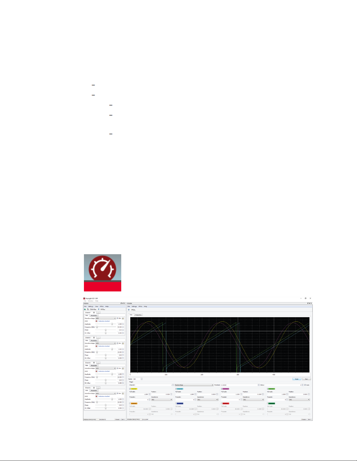
1. 1 Keysight SD1 SFP Software
1. 1. 1 Overview of Keysight SD1 SFP Software
KeysightM3201A/M3202A PXIe AWGs, M3100A/M3102A PXIe Digitizers, and
M3300A/M3302A PXIe AWG/Digitizer Combos can be operated as classical benchtop instruments using Keysight SD1 SFP software; no programming is required.
When SD1 SFP is opened, it identifies all Keysight PXIe hardware modules that are
connected to the embedded controller or desktop computer, and opens a
corresponding soft front panel for each piece of hardware.
SD1 SFP
Keysight M3100A/M3102A PXIe Digitizer User's Guide 1
Page 8
1 Overview of Keysight Software and Programming Tools
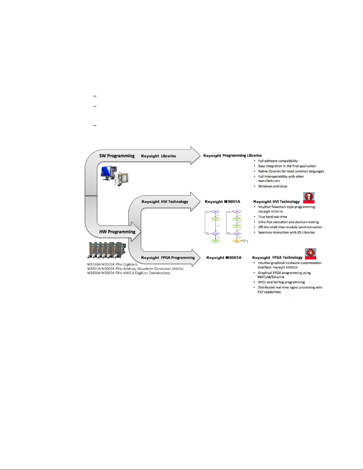
1. 2 Keysight Programming Tools
The following programming tools are available to control KeysightM3100A/M3102A
PXIe Digitizers, M3201A/M3202A PXIe AWGs, and M3300A/M3302A PXIe AWG
&Digitizer Combinations:
Keysight SD1 Programming Libraries onpage3
KeysightM3601A HardVirtualInstrument(HVI) DesignEnvironmentSoftware
onpage4
KeysightM3602A FPGADesignEnvironmentSoftware onpage8
2 Keysight M3100A/M3102A PXIe Digitizer User's Guide
Page 9

1 Overview of Keysight Software and Programming Tools
1. 2. 1 Keysight SD1 Programming Libraries
Keysight supplies a comprehensive set of highly optimized software instructions that
can control off-the-shelf functionalities of Keysight hardware. These software
instructions are compiled into the Keysight SD1 Programming Libraries. Programs can
be written with these libraries and run on an embedded controller or desktop
computer.
The use of customizable software to create user-defined control, test and
measurement systems is commonly referred as Virtual Instrumentation. In Keysight
documentation, the concept of a Virtual Instrument (or VI) describes user software
that uses programming libraries and is executed by a computer.
Keysight provides native programming libraries for a comprehensive set of
programming languages, such as C, C++, Visual Studio (VC++, C#, VB), MATLAB,
National Instruments LabVIEW, Python, etc., ensuring full software compatibility and
seamless multivendor integration. Keysight also provides dynamic libraries, for
example: DLLs, that can be used in virtually any programming language.
Keysight native programming libraries ensure full compatibility, providing effortless
and seamless software integration user interaction, etc. The I/O modules run in
parallel, completely synchronized, and exchange data and decisions in real-time. The
result is a set of modules that behave like a single integrated real-time instrument.
For more information, refer to the following sections:
Keysight Supplied Native Programming Libraries onpage23
Support for Other Programming Languagesonpage24
Functions in SD1 Programming Librariesonpage25
SD_Module Functionsonpage28
SD_AIN Functions onpage38
SD_Module Functions (M3601A HVI-related)onpage74
SD_Module Functions (M3602A FPGA-related)onpage78
Keysight M3100A/M3102A PXIe Digitizer User's Guide 3
Page 10

1 Overview of Keysight Software and Programming Tools
1. 2. 2 KeysightM3601A HardVirtualInstrument(HVI)
DesignEnvironmentSoftware
KeysightM3201A/M3202A PXIe AWGs and M3100A/M3102A
PXIe digitizer must have OptionHV1 to use Keysight M3601A
software; OptionHV1 is only available at time of purchase.
The following section is only an overview of the Keysight M3601A
software; To learn how to use Keysight M3601A software, refer to
the User'sGuide for the [3] KeysightM3601A Hard Virtual
Instrument (HVI) DesignEnvironment Software.
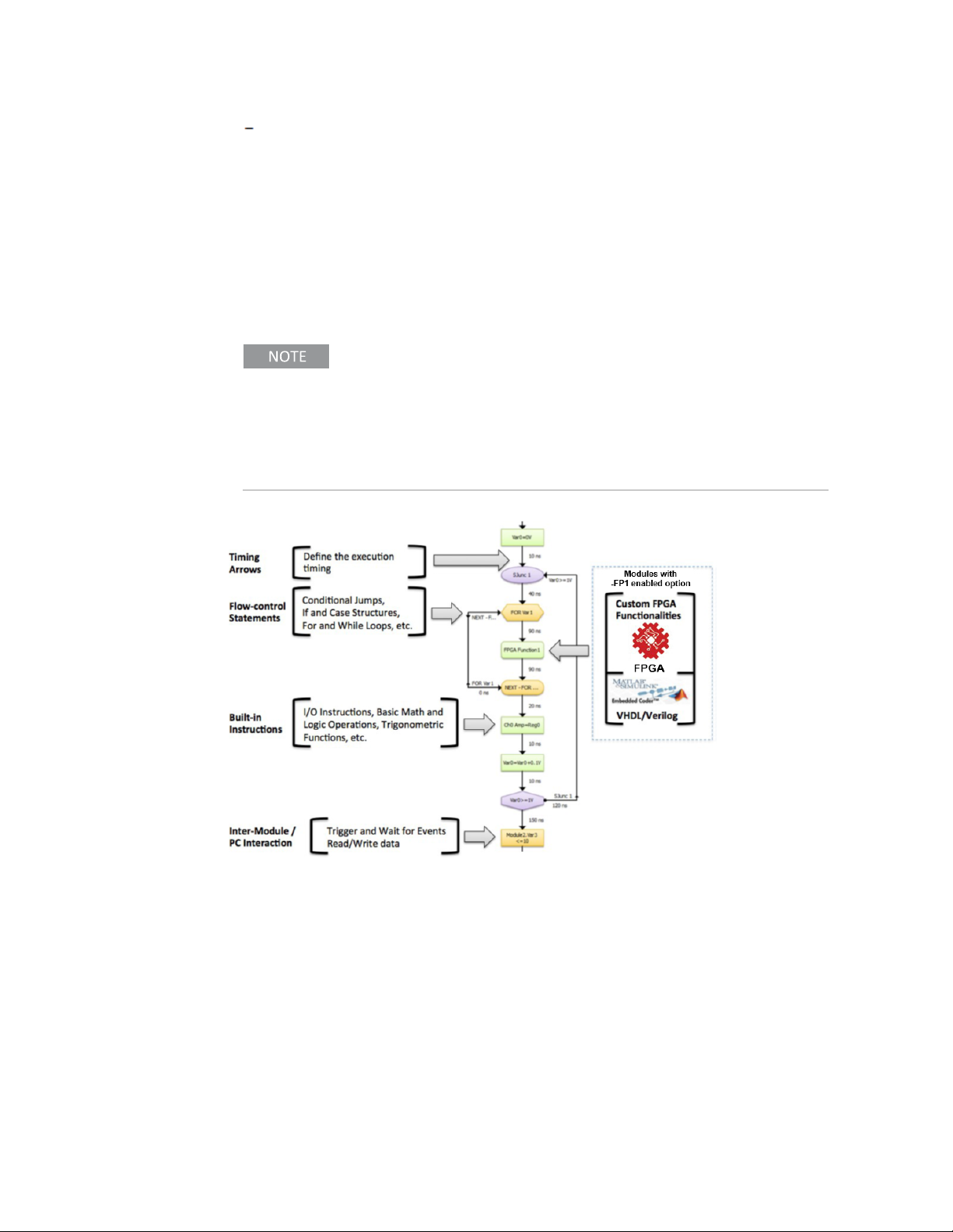
1. 2. 2. 1 HVI Programming
Keysight’s HVI technology provides the capability to create time-deterministic
execution sequences that are executed by the KeysightM3201A/M3202A PXIe AWGs
and M3100A/M3102A PXIe digitizers with Option HV1. HVIs are programmed with
Keysight M3601A, an HVI design environment with a user-friendly flowchart-style
interface.
1. 2. 2. 2 HVI Functions
Keysight’s HVI Technology uses the same programming instructions that are
available in the Keysight SD1 Programming Libraries, with the difference that in an
HVI, those instructions are executed by the hardware modules in hard real-time, not
by the embeded controller or desktopcomputer.
Virtual Instrumentation is the use of customizable software and modular hardware to
create user-defined measurement systems, called Virtual Instruments (VIs). Thus, a
Virtual Instrument is based on a software which is executed by a computer, and
therefore its real-time performance (speed, latency, etc.) is limited by the computer
and by its operating system. In many cases, this real-time performance might not be
enough for the application, even with a real-time operating system. In addition, many
modern applications require tight triggering and precise intermodule synchronization,
making the development of final systems very complex and time consuming. For all
these applications, Keysight has developed an exclusive technology called Hard
Virtual Instrumentation. In a hard virtual instrument (HVI), the user application is
executed by the hardware modules independently of the computer, which stays free
for other VI tasks, like visualization.
HVIs vs. VIs: Virtual Instrumentation is fully supported making use
of the Keysight SD1 Programming Libraries. On the other hand,
Keysight’s exclusive Hard Virtual Instrumentation (HVI)
technology provides the capability to create time-deterministic
4 Keysight M3100A/M3102A PXIe Digitizer User's Guide
Page 11

1 Overview of Keysight Software and Programming Tools
execution sequences which are executed by the hardware
modules in parallel and with perfect intermodule synchronization.
HVIs provide the same programming instructions available in the
Keysight SD1 Programming Libraries.
HVIs are programmed with Keysight M3601A Hard Virtual Instrument (HVI) Design
Environment Software, with a user-friendly flowchart-style interface, compatible with
KeysightM3201A/M3202A PXIe AWGs and M3100A/M3102A PXIe digitizers.
Keysight M3100A/M3102A PXIe Digitizer User's Guide 5
Page 12

1 Overview of Keysight Software and Programming Tools
M3601A
Keysight M3601A is based on flowchart programming, providing an easyto-use environment to develop hard real-time applications.
Keysight M3601A Hard Virtual Instrument (HVI) Design Environment Software
provides:
Ultra-fast hard real time execution, processing, and decision making: Execution
is hardware-timed and can be as fast as 1 nanosecond, matching very high-performance FPGA-based systems and outperforming any real-time operating system.
User-friendly flowchart-style programming interface: Keysight M3601A
provides an intuitive flowchart-style programming environment that makes
HVIprogramming extremely fast and easy. Using M3601A and its set of built-in
instructions (the same instructions available for VIs), the user can program the
hardware modules without any knowledge in FPGA technology, VHDL, etc.
Off-the-shelf intermodule synchronization and data exchange: Each HVI is
defined by a group of hardware modules which work perfectly synchronized,
without the need of any external trigger or additional external hardware.
In addition, Keysight modules exchange data and decisions for ultra-fast control algorithms.
Complete robustness: Execution is performed by hardware, without operating
system, and independently of the user PC.
Seamless integration with Keysight FPGA technology: HVIs can interact with
user-defined FPGA functions, making the real-time processing capabilities of
HVIs unlimited.
6 Keysight M3100A/M3102A PXIe Digitizer User's Guide
Page 13
1 Overview of Keysight Software and Programming Tools
Seamless integration with Keysight SD1 Programming Libraries: In a complex
control or test system, there are still some non- time-critical tasks that can
only be performed by a VI, like for example: user interaction, visualization, or
processing and decision tasks which are too complex to be implemented by
hardware. Therefore, in a real application, the combination of VIs and HVIs is
required. This task can be performed seamlessly with Keysight programming
tools, for example, the user can have many HVIs and can control them from a VI
using instructions like start, stop, pause, etc.
Tip: New hardware functionalities without FPGA programming:
Keysight’s HVI technology is the perfect tool to create new
hardware functionalities with FPGA-like performance and without
any FPGA programmingknowledge. Users can create a repository
of HVIs that can be launched from VIs using the Keysight SD1
Programming Libraries.
In an HVI, all Keysight modules run in parallel and completely synchronized,
executing one flowchart per module. This results in simpler systems without the need
of triggers.
Keysight M3100A/M3102A PXIe Digitizer User's Guide 7
Page 14

1 Overview of Keysight Software and Programming Tools
1. 2. 3 KeysightM3602A FPGADesignEnvironmentSoftware
Keysight FPGA programming technology is managed with Keysight M3602A FPGA
Design Environment Software, an intuitive graphical FPGA programming environment.
Keysight M3201A/M3202A PXIe AWGs and M3100A/M3102A
PXIe digitizers must have OptionFP1 to use Keysight M3602A
software; OptionFP1 is only available at time of purchase.
The following section is only an overview of the Keysight M3602A
software; To learn how to use Keysight M3602A software, refer to
the User'sGuide for the KeysightM3602A FPGA Design
Environment Software.
Some applications require the use of custom on-board real-time processing which
might not be covered by the comprehensive off-the-shelf functionalities of standard
hardware products. For these applications, Keysight supplies Option FP1 (Enabled
FPGA Programming), that provide the capability to program the on-board FPGA.
All Keysight M3201A/M3202A PXIe AWGs and M3100A/M3102A PXIe digitizers can
add OptionFP1, which provide the same built-in functionalities of their standard
counterparts, giving the users more time to focus on their specific functionalities. For
example, using OptionFP1 on a Keysight M3100A/M3102A PXIe digitizer, the user
has all the off-the-shelf functionalities of the hardware (data capture, triggering, etc.),
but custom real-time FPGA processing can be added in the data path, between the
acquisition and the transmission of data to the computer.
8 Keysight M3100A/M3102A PXIe Digitizer User's Guide
Page 15

1 Overview of Keysight Software and Programming Tools
M3602A
FPGA programming made simple: Full language compatibility
(including the graphical environment MATLAB/Simulink) and an
easy-to-use FPGA graphical IDE, make Keysight FPGA
programming extremely simple.
An FPGA programming environment provides the following features:
Keysight M3602A is a complete FPGA programming environment that allows the user
to customize Keysight M3201A/M3202A PXIe AWGs and M3100A/M3102A PXIe
digitizers with Option FP1. Keysight M3602A provides the necessary tools to design,
compile, and program the FPGA of the module.
User-friendly graphical FPGA programming environment:
Complete platform, from design to FPGA programming: Keysight M3602A
provides the necessary tools to design, compile, and program the FPGA of the
module.
5x faster project development
Graphical environment without performance penalty
FPGA know-how requirement minimized: The graphical environment provides a
tool which does not require an extensive know-how in FPGA technology, improving the learning curve.
Streamlined design process:
Ready-to-use Keysight Block Library: M3602A provides a continuously-growing
library of blocks which reduces the need for custom FPGA-code development.
Include VHDL, Verilog, or Xilinx VIVADO/ISE projects: Experienced FPGA users
can squeeze the power of the onboard FPGA.
Include MATLAB/Simulink
Projects: MATLAB/Simulinkin conjunction with Xilinx
System Generator for DSP provides a powerful tool to implement digital signal
processing. The user can go from the design/simulation power of MATLAB/Simulink to
M3602A code in just a few clicks.
Include Xilinx CORE Generator IP cores: Xilinx CORE Generator can be launched
by M3602A to create IP cores that can be seamlessly included in the design.
Keysight M3100A/M3102A PXIe Digitizer User's Guide 9
Page 16

1 Overview of Keysight Software and Programming Tools
Add and remove built-in resources to free up space: The user can remove unused
built-in resources to free up more FPGA space.
One-click compiling and programming:
3x faster ultra-secure cloud FPGA compiling: An ultra-fast cloud compiling system provides up to 3 times faster compiling. An ultra-secure TLS encrypted communication protects the IP of the user.
100x faster hot programming via PCI Express without rebooting: Hardware can
be reprogrammed without external cables and without rebooting the system.
Design Process: Customization vs. Complete Design
Keysight FPGA technology allows the user to customize Keysight M3201A/M3202A
PXIe AWGs and M3100A/M3102A PXIe digitizers with Option FP1; these products are
delivered with all the off-the-shelf functionalities of the standard products, and
therefore the development time is dramatically reduced. The user can focus
exclusively on expanding the functionality of the standard instrument, instead of
developing a complete new one.
In Keysight M3602A, FPGA code is represented as boxes (called blocks) with IO ports.
An empty project contains the ”Default Product Blocks” (off-the-shelf functionalities),
and the ”Design IO Blocks” that provide the outer interface of the design. The user can
add/remove blocks from the Keysight Block Library, External Blocks, or Xilinx IP cores.
1. 2. 3. 1 FPGA Programming Overview
Keysight FPGA Block Library: Keysight M3602A provides a readyto-use FPGA block library that reduces the requirement on FPGA
know-how. Please check the M3602A User Guide to see a full
description of the available FPGA blocks.
Keysight M3602A provides up to x3 faster FPGA compiling and hot programming
without having to reboot the system.
10 Keysight M3100A/M3102A PXIe Digitizer User's Guide
Page 17

1 Overview of Keysight Software and Programming Tools
M3602A Diagram Blocks
M3602A ControlCH Block
This block provides all the control parameters set by the user software using the
Keysight SD1 Programming Libraries.
Parameters
Name Description
Outputs
AngleModCtrl Angle modulation control (frequency or phase)
AmpModCtrl Amplitude modulation control
WaveShape Selects the output waveform
Amplitude Signal amplitude value
Offset DC offset value
Frequency Signal frequency value
Phase Signal phase value
PhaseRst Signal to reset the phase of the function generator
Keysight M3100A/M3102A PXIe Digitizer User's Guide 11
Page 18

1 Overview of Keysight Software and Programming Tools
M3602A AWG Block
This block is the Dual Arbitrary Waveform Generator.
Parameters
Name Description
Inputs
Control AWG operation control
QueueCtrl AWG queue control
Outputs
Data_A Waveform A output (for dual waveforms), main waveform for single waveforms
Data_B Waveform B output (for dual waveforms only)
WFstart Signal that indicates when the AWG starts a waveform
12 Keysight M3100A/M3102A PXIe Digitizer User's Guide
Page 19

1 Overview of Keysight Software and Programming Tools
M3602A FuncGen Block
This block is a function generator with angle modulation capabilities.
Parameters
Name Description
Inputs
AngleModCtrl Configures the angle modulation (frequency or phase)
WaveShape Selects the output waveform between Sine, Triangular or Square
AWGsignal Arbitrary waveform coming from the AWG. It is used as the modulating signal
Frequency Signal frequency value
Phase Signal phase value
WFstart Signal that indicates when the AWG signal starts a waveform
PhaseRst Signal to reset the phase of the function generator
Outputs
WaveShapeOut Indicates which of the output signals is valid
Sine Sinusoidal waveform
Triangular Triangular waveform
Sawtooth Not used
Square Square waveform
Keysight M3100A/M3102A PXIe Digitizer User's Guide 13
Page 20

1 Overview of Keysight Software and Programming Tools
M3602A ModGain Block
This block has the following functionalities:
It selects the output waveform between Sine, Triangular, Sawtooth, Square,
Partner Channel, or AWG.
It modulates the amplitude and the offset of the signal
Parameters
Name Description
Inputs
AmpModCtrl Configures the amplitude modulator
WaveShape Selects the output waveform between:
Sine, Triangular, Square, Partner Channel, or AWG
WFstart Signal that indicates when the AWGsignal starts a waveform
Amplitude Signal amplitude value
OffsetDC offset value
Sine Sinusoidal waveform coming from the Function Generator
Triangular Triangular waveform coming from the Function Generator
Sawtooth Not used
Square Square waveform coming from the Function Generator
PartnerIn Waveform coming from the Partner Channel.
Used only in odd channels
AWGsignal Arbitrary waveform coming from the AWG. It can be routed
to SignalOut, or it can be used as the modulating signal
Outputs
SignalOut Output signal
PartnerOut Copy of the output signal used for the even Partner Channel.
14 Keysight M3100A/M3102A PXIe Digitizer User's Guide
Page 21

1 Overview of Keysight Software and Programming Tools
M3602A DOut Block
This block sends the data directly to the hardware analog output.
Parameters
Name Description
Inputs
data data to be sent to the analog output channel
Keysight M3100A/M3102A PXIe Digitizer User's Guide 15
Page 22

16 Keysight M3100A/M3102A PXIe Digitizer User's Guide
Page 23

2 Using Keysight SD1 SFP Software
This chapter describes how to use Keysight SD1 SFP software:
Main Soft Front Panel Controls onpage18
Input Setting Controlsonpage19
Time Domain Controls (Scope Like Operation)onpage20
Frequency Domain Controls (Spectrum Analyzer Functionality)onpage21
Window Types Used in FFT Functionsonpage22
KeysightM3201A/M3202A PXIe AWGs, M3100A/M3102A PXIe Digitizers, and
M3300A/M3302A PXIe AWG/Digitizer Combos can be operated as classical benchtop instruments using Keysight SD1 SFP software; no programming is required.
When SD1 SFP is opened, it identifies all Keysight PXIe hardware modules that are
connected to the embedded controller or desktop computer and opens a
corresponding soft front panel for each piece of hardware.
2 Using Keysight SD1 SFP Software
SD1 SFP
Keysight SD1 SFP Software provides a fast and intuitive way of operating
KeysightM3201A/M3202A PXIe AWGs, M3100A/M3102A PXIe Digitizers, and
M3300A/M3302A PXIe AWG/Digitizer Combos.
Keysight M3100A/M3102A PXIe Digitizer User's Guide 17
Page 24

2 Using Keysight SD1 SFP Software
2. 1 Main Soft Front Panel Controls
The main soft front panel for the M3100A/M3102A PXIe Digitizers appear
automatically when SD1SFP is launched and the module is connected to the chassis.
If there are no modules available, SD1 SFP will launch "Demo Offline" modules.
When SD1 SFP is launched, the soft front panel appears populated with all available
channels, waiting for the user to configure the input ”Channels”. The soft front panel
provides both time domain (scope like functionality) and frequency domain
(spectrumanalyzer like functionality).
18 Keysight M3100A/M3102A PXIe Digitizer User's Guide
Page 25

2. 2 Input Setting Controls
Workflow to Use the Digitizer
2 Using Keysight SD1 SFP Software
1. Select a scale value.
2. Set a prescaler value.
3. Set a coupling and impedance value.
4. Activate the cahnnel.
Keysight M3100A/M3102A PXIe Digitizer User's Guide 19
Page 26

2 Using Keysight SD1 SFP Software
2. 3 Time Domain Controls (Scope Like Operation)
Work flow to Use the Digitizer as a Scope
1. Select channels
2. Define acquisition type (single or run)
3. Set coupling and impedance
4. Define triggering:
a. channel (any of the channels)
b. edge (positive, negative, both)
c. threshold (within full-scale settings of the channel)
d. delay
e. mode (normal, auto, slave)
20 Keysight M3100A/M3102A PXIe Digitizer User's Guide
Page 27

2 Using Keysight SD1 SFP Software
2. 4 Frequency Domain Controls (Spectrum Analyzer Functionality)
Workflow to Use the Digitizer as a Spectrum Analyzer
1. Select channel
2. Define number of FFT points (set resolution)
3. Set windowing option (see windows types below)
4. Set dynamic range:
a. - scale (Linear or dB)
b. -set max
c. -define range
Keysight M3100A/M3102A PXIe Digitizer User's Guide 21
Page 28

2 Using Keysight SD1 SFP Software
Window is a mathematical function that is zero-valued outside of some chosen
interval and it is used in applications including spectral analysis.
2. 5 Window Types Used in FFT Functions
Option Description Name Value
Rectangular Simplest B-spine window WINDOW_
Bartlett Hybrid window WINDOW_BARTLETT 1
Hanning Side-lobes roll off about 18 dB per octave WINDOW_HANNING 2
Hamming Optimized to minimize the maximum nearest side lobe WINDOW_HAMMING 3
Blackman Higher-order generalized cosine windows for applic-
ations that require windowing by the convolution in the
frequency-domain
Kaiser Adjustable window maximizing energy concentration in
the main lobe
Gauss Adjustable window (can be used for quadratic inter-
polation in frequency estimation)
Programming Definitions
RECTANGULAR
WINDOW_BLACKMAN 4
WINDOW_KAISER 5
WINDOW_GAUSS 6
0
(default)
22 Keysight M3100A/M3102A PXIe Digitizer User's Guide
Page 29

3 Keysight SD1 Command Reference
This chapter contains the following sections:
Keysight Supplied Native Programming Libraries onpage23
Support for Other Programming Languagesonpage24
Functions in SD1 Programming Librariesonpage25
SD_Module Functionsonpage28
SD_AIN Functions onpage38
SD_Module Functions (M3601A HVI-related)onpage74
SD_Module Functions (M3602A FPGA-related)onpage78
Programs can run on an embedded controller or desktop computer and be controlled
with Keysight SD1 Programming Libraries. Keysight supplies a comprehensive set of
highly optimized software instructions that controls off-the-shelf functionalities of
Keysight hardware. These software instructions are compiled into the Keysight SD1
Programming Libraries. The use of customizable software to create user-defined
control, test and measurement systems is commonly referred as Virtual
Instrumentation. In Keysight documentation, the concept of a Virtual Instrument (or
VI) describes user software that uses programming libraries and is executed by a
computer.
3 Keysight SD1 Command Reference
3. 1 Keysight Supplied Native Programming Libraries
Keysight provides ready-to-use native programming libraries for a comprehensive set
of programming languages, such as C, C++, Visual Studio (VC++, C#, VB), MATLAB,
National Instruments LabVIEW, Python, etc., ensuring full software compatibility and
seamless multivendor integration. Ready-to-use native libraries are supplied for the
following programming languages and compilers:
Language Compiler Library Files
C Microsoft Visual Studio . NET .NET Library *.dll
MinGW (Qt), GCC C Library *.h, *.a
Any C compiler C Library *.h, *.lib
C++ Microsoft Visual Studio . NET .NET Library *.dll
MinGW (Qt), GCC C++ Library *.h, *.a
C++ Builder / Turbo C++ C++ Library *.h, *.lib
C# Microsoft Visual Studio .NET .NET Library *.dll
MATLAB MathWorks MATLAB .NET Library *.dll
Python Any Python compiler Python Library *.py
Basic Microsoft Visual Studio .NET .NET Library *.dll
LabVIEW National Instruments LabVIEW LabVIEW Library *.vi
Keysight M3100A/M3102A PXIe Digitizer User's Guide 23
Page 30

3 Keysight SD1 Command Reference
3. 2 Support for Other Programming Languages
Keysight provides dynamic libraries, e.g. DLLs, that can be used in virtually any
programming language. Dynamic-link libraries are compatible with any programming
language that has a compiler capable of performing dynamic linking. Here are some
case examples:
Compilers not listed above.
Other programming languages: Java, PHP, Perl, Fortran, Pascal.
Computer Algebra Systems (CAS): Wolfram Mathematica, Maplesoft Maple.
Dynamic-link libraries available:
Exported Functions Language Operating System Files
C Microsoft Windows *.dll
DLL function prototypes: The exported functions of the dynamic
libraries have the same prototype as their counterparts of the
static libraries.
Function Parameters: Some of the parameters of the library
functions are language dependent. The table of input and output
parameters for each function is a conceptual description,
therefore, the user must check the specific language function to
see how to use it. One example are the ID parameters (moduleID,
etc.), which identify objects in non object-oriented languages. In
object-oriented languages, the objects are identified by their
instances and therefore the IDs are not present.
Function Names: Some programming languages like C++ or
LabVIEW have a feature called function overloading or
polymorphism, that allows creating several functions with the
same name, but with different input/output parameters. In
languages without this feature, functions with different
parameters must have different names.
24 Keysight M3100A/M3102A PXIe Digitizer User's Guide
Page 31

3 Keysight SD1 Command Reference
3. 3 Functions in SD1 Programming Libraries
The following functions are available in Keysight SD1 Programming Libraries.
SD_Module Functionsonpage28
Function Name Comments
openonpage28 Initializes a hardware module and must be called before using
any other module-related function.
closeonpage30 Releases all resources that were allocated for a module with
openonpage28 and must always be called before exiting the
application.
moduleCountonpage31 Returns the number of Keysight SD1 modules in the system.
getProductNameonpage32 Returns the product name of the specified module.
getSerialNumberonpage33 Returns the serial number of the specified module.
getChassisonpage34 Returns the chassis number of where a module is located.
getSlotonpage35 Returns the slot number of where a module is located.
PXItriggerWriteonpage36 Sets the digital value of a PXI trigger in the PXI backplane.
Only available in PXI/PXI Express form factors.
PXItriggerReadonpage37 Reads the digital value of a PXI trigger in the PXI backplane.
Only available in PXI/PXI Express form factors.
SD_AIN Functions onpage38
Function Name Comments
channelInputConfigonpage38 Configures the input full scale, impedance and coupling.
channelPrescalerConfigonpage39 Configures the input prescaler.
channelTriggerConfigonpage40 Configures the analog trigger block for each channel Analog
Trigger.
DAQconfigonpage41 Configures the acquisition of words in two possible reading
modes.
DAQdigitalTriggerConfigonpage42 Configures the digital hardware triggers for the selected DAQ
Trigger.
DAQanalogTriggerConfigonpage43 Configures the analog hardware trigger for the selected DAQ
Trigger.
DAQreadonpage44 Reads the words acquired with the selected DAQ Data
Acquisition (DAQs).
DAQstartonpage46 Starts an acquisition on the selected DAQs Data Acquisition
(DAQs).
DAQstartMultipleonpage47 Starts an acquisition on the selected DAQs Data Acquisition
(DAQs).
DAQstoponpage48 Stops the Data Acquisition (DAQs).
DAQstopMultipleonpage49 Stops multiple channels of Data Acquisition (DAQs).
DAQpauseonpage50 Pauses the Data Acquisition (DAQs).
DAQpauseMultipleonpage51 Pauses multiple channels of Data Acquisition (DAQs).
DAQresumeonpage52 Resumes acquisition on the selected DAQs.
Keysight M3100A/M3102A PXIe Digitizer User's Guide 25
Page 32

3 Keysight SD1 Command Reference
Function Name Comments
Keysight SD1 Command
Referenceonpage23
DAQflushonpage54 Flushes the acquisition buffers and resets the acquisition
DAQflushMultipleonpage55 Flushes the acquisition buffers and resets the acquisition
DAQtriggeronpage56 Triggers the acquisition of words in the selected DAQs
DAQtriggerMultipleonpage57 Triggers the acquisition of words in the selected DAQ provided
DAQcounterReadonpage58 Returns the number of available points to be read from the
triggerIOconfigonpage59 Configures the trigger connector/line direction.
triggerIOwriteonpage60 Sets the trigger output and synchronization mode.
triggerIOreadonpage61 Reads the trigger input I/O Triggers.
clockSetFrequencyonpage62 Sets the module clock frequency.
clockGetFrequencyonpage63 Returns the real hardware clock frequency.
clockGetSyncFrequencyonpage64 Returns the frequency of the synchronization clock.
clockResetPhaseonpage65 Sets the module in a synchronized state, waiting for the first
DAQbufferPoolConfigonpage66 Configures buffer pool that will be filled with the data of the
DAQbufferAddonpage68 Adds an additional buffer to the channel’s previously
DAQbufferGetonpage69 Retrieves a filled buffer from the channel buffer pool. You have
DAQbufferPoolReleaseonpage70 Releases the channel buffer pool and its resources. After this
DAQbufferRemoveonpage71 Requests that a buffer be removed from the channel buffer
FFTonpage72 Calculates the FFT of data captured by DAQread for the
Resumes multiple channels of acquisition on the selected
DAQs.
counter included in a data acquisition block.
counter included in a Data Acquisition block.
provided that they are configured for VI/HVI Trigger.
that they are configured for VI/HVI Trigger.
intermediate buffer.
trigger to reset the phase of the internal clocks CLKsync and
CLKsys.
channel to be transferred to PC.
configured pool.
to call DAQbufferAdd with this buffer so the buffer can be used
again.
function is called, you need to call DAQbufferRemove
consecutively to get all buffers back and release them.
pool. If a NULL pointer is returned, no more buffers remain in
the buffer pool. Returned buffer is a previously added buffer
from the user and the user has to release/delete it.
selected channel. FFT frequency range goes from 0 to fs/2.
26 Keysight M3100A/M3102A PXIe Digitizer User's Guide
Page 33

3 Keysight SD1 Command Reference
SD_Module Functions (M3601A HVI-related)onpage74
Function Name Comments
writeRegisteronpage74 Writes a value in an HVI register of a hardware module
(Option HV1 required).
readRegisteronpage76 Reads a value from an HVI register of a hardware module
(Option HV1 required).
SD_Module Functions (M3602A FPGA-related)onpage78
Function Name Comments
FPGAwritePCportonpage78 Writes data at the PCport FPGA block
(Option FP1 required).
FPGAreadPCportonpage80 Reads data at the PCport FPGA block
(Option FP1 required).
Keysight M3100A/M3102A PXIe Digitizer User's Guide 27
Page 34

3 Keysight SD1 Command Reference
3. 3. 1 SD_Module Functions
3. 3. 1. 1 open
Initializes a hardware module and must be called before using any other modulerelated function.
A module can be opened using the serial number or the chassis and slot number.
Using the serial number ensures the same module is always opened regardless of its
chassis or slot location.
Parameters
Name Description
Inputs
productName Module's product name (for example, "M3202A").
serialNumber Module's serial number (for example, "ES5641").
chassis Chassis number where the module is located.
slot Slot number in the chassis where the module is located.
compatibility Forces the channel numbers to be compatible with legacy models.
errorIn (LabVIEW only) If it contains an error, the function will not be executed
Outputs
moduleID (Non-object-oriented languages only) Module identifier
errorOut See Error Codesonpage83
The product name can be found on the product
or can be retrieved with getProductNameonpage32.
The serial number can be found on the product
or can be retrieved with getSerialNumberonpage33.
The chassis number can be found in Keysight SD1 software
or can be retrieved with getChassisonpage34.
The slot number can be found on the chassis
or can be retrieved with getSlotonpage35.
Channel numbering (channel enumeration) can start as CH0 or CH1.
See Channel Numbering and Compatibility Mode.
and errorIn will be passed to errorOut
or a negative number that indicates an error, see Error
Codesonpage83.
C
int SD_Module_openWithSerialNumber(const char* productName, const char*
serialNumber);
int SD_Module_openWithSlot(const char* productName, int chassis, int slot);
int SD_Module_openWithSerialNumberCompatibility(const char* productName,
const char* serialNumber, int compatibility);
int SD_Module_openWithSlotCompatibility(const char* productName, int chassis,
int slot, int compatibility);
28 Keysight M3100A/M3102A PXIe Digitizer User's Guide
Page 35

3 Keysight SD1 Command Reference
C++
int SD_Module::open(const char* productName, const char* serialNumber);
int SD_Module::open(const char* productName, int chassis, int slot);
int SD_Module::open(const char* productName, const char* serialNumber, int
compatibility);
int SD_Module::open(const char* productName, int chassis, int slot, int
compatibility);
Visual Studio .NET, MATLAB
int SD_Module::open(string productName, string serialNumber);
int SD_Module::open(string productName, int chassis, int slot);
int SD_Module::open(string productName, string serialNumber, int
compatibility);
int SD_Module::open(string productName, int chassis, int slot, int
compatibility);
Python
SD_Module.openWithSerialNumber(productName, serialNumber)
SD_Module.openWithSlot(productName, chassis, slot)
SD_Module.openWithSerialNumberCompatibility(productName, serialNumber,
compatibility)
SD_Module.openWithSlotCompatibility(productName, chassis, slot,
compatibility)
LabVIEW
openWithSerialNumber.vi
openWithSlot.vi
M3601A
Available: No
Keysight M3100A/M3102A PXIe Digitizer User's Guide 29
Page 36

3 Keysight SD1 Command Reference
3. 3. 1. 2 close
Releases all resources that were allocated for a module with openonpage28
and must always be called before exiting the application.
Parameters
Name Description
Inputs
moduleID (Non-object-oriented languages only) Module identifier, returned by openonpage28
errorIn (LabVIEW only) If it contains an error, the function will not be executed and errorIn will be
passed to errorOut.
Outputs
errorOut See Error Codesonpage83
C
int SD_Module_close(int moduleID);
C++
int SD_Module::close();
Visual Studio .NET, MATLAB
int SD_Module::close();
Python
SD_Module.close()
LabVIEW
close.vi
M3601A
Available: No
30 Keysight M3100A/M3102A PXIe Digitizer User's Guide
Page 37

3 Keysight SD1 Command Reference
3. 3. 1. 3 moduleCount
Returns the number of Keysight SD1 modules (M31xxA/M32xxA/M33xxA) installed in
the system.
Static Function: (Object-oriented languages only)
moduleCount is a static function
Parameters
Name Description
Inputs
errorIn (LabVIEW only) If it contains an error, the function will not be executed and errorIn will be
passed to errorOut
Outputs
nModules Number of Keysight SD1 modules installed in the system.
Negative numbers indicate an error, see Error Codesonpage83.
errorOut (LabVIEW only) See Error Codesonpage83
C
int SD_Module_moduleCount();
C++
int SD_Module::moduleCount();
Visual Studio .NET, MATLAB
int SD_Module::moduleCount();
Python
SD_Module.moduleCount()
LabVIEW
Available: No
M3601A
Available: No
Keysight M3100A/M3102A PXIe Digitizer User's Guide 31
Page 38

3 Keysight SD1 Command Reference
3. 3. 1. 4 getProductName
Returns the product name of the specified module.
Parameters
Name Description
Inputs
index Module index. It must be in the range (0 to nModules-1),
chassis Chassis number where the module is located.
slot Slot number in the chassis where the module is located.
errorIn (LabVIEW only) If it contains an error, the function will not be
Outputs
productName Product name of the specified module.
errorOut See Error Codesonpage83
Static Function: (Object-oriented languages only)
getProductName is a static function
where nModules is returned by moduleCountonpage31.
The chassis number can be found in Keysight SD1 software
or can be retrieved with getChassisonpage34.
The slot number can be found on the chassis
or can be retrieved with getSlotonpage35.
executed and errorIn will be passed to errorOut.
This product name can be used in openonpage28.
C
int SD_Module_getProductNameByIndex(int index, char *productName);
int SD_Module_getProductNameBySlot(int chassis, int slot, char* productName);
C++
int SD_Module::getProductName(int index, char *productName);
int SD_Module::getProductName(int chassis, int slot, char* productName);
Visual Studio .NET, MATLAB
int SD_Module::getProductName(int index, string productName);
int SD_Module::getProductName(int chassis, int slot, string productName);
Python
SD_Module.getProductNameByIndex(index, productName)
SD_Module.getProductNameBySlot(chassis, slot, productName)
LabVIEW
Available: No
M3601A
Available: No
32 Keysight M3100A/M3102A PXIe Digitizer User's Guide
Page 39

3 Keysight SD1 Command Reference
3. 3. 1. 5 getSerialNumber
Returns the serial number of the specified module.
Static Function: (Object-oriented languages only)
getSerialNumber is a static function
Parameters
Name Description
Inputs
index Module index. It must be in the range (0 to nModules-1),
where nModules is returned by moduleCountonpage31.
chassis Chassis number where the module is located.
The chassis number can be found in Keysight SD1 software
or can be retrieved with getChassisonpage34.
slot Slot number in the chassis where the module is located.
The slot number can be found on the chassis
or can be retrieved with getSlotonpage35.
errorIn (LabVIEW only) If it contains an error, the function will not be executed
and errorIn will be passed to errorOut
Outputs
serialNumber Serial number of the specified module.
This serial number can be used in openonpage28.
errorOut See Error Codesonpage83
C
int SD_Module_getSerialNumberByIndex(int index, char *serialNumber);
int SD_Module_getSerialNumberBySlot(int chassis, int slot, char*
serialNumber);
C++
int SD_Module::getSerialNumber(int index, char *serialNumber);
int SD_Module::getSerialNumber(int chassis, int slot, char* serialNumber);
Visual Studio .NET, MATLAB
int SD_Module::getSerialNumber(int index, string serialNumber);
int SD_Module::getSerialNumber(int chassis, int slot, string serialNumber);
Python
SD_Module.getSerialNumberByIndex(index, serialNumber)
SD_Module.getSerialNumberBySlot(chassis, slot, serialNumber)
LabVIEW
Available: No
M3601A
Available: No
Keysight M3100A/M3102A PXIe Digitizer User's Guide 33
Page 40

3 Keysight SD1 Command Reference
3. 3. 1. 6 getChassis
Returns the chassis number of where a module is located.
Parameters
Name Description
Inputs
index Module index. It must be in the range (0 to nModules-1),
errorIn (LabVIEW only) If it contains an error, the function will not be executed and
Outputs
chassis Chassis number of where a module is located.
errorOut (LabVIEW only) See Error Codesonpage83
Static Function: (Object-oriented languages only)
getChassis is a static function
where nModules is returned by moduleCountonpage31.
errorIn will be passed to errorOut.
Negative numbers indicate an error, see Error Codesonpage83.
C
int SD_Module_getChassis(int index);
C++
int SD_Module::getChassis(int index);
Visual Studio .NET, MATLAB
int SD_Module::getChassis(int index);
Python
SD_Module.getChassis()
SD_Module.getChassisByIndex(index)
LabVIEW
Available: No
M3601A
Available: No
34 Keysight M3100A/M3102A PXIe Digitizer User's Guide
Page 41

3 Keysight SD1 Command Reference
3. 3. 1. 7 getSlot
Returns the slot number of where a module is located in the chassis.
Static Function: (Object-oriented languages only)
getSlot is a static function
Parameters
Name Description
Inputs
index Module index. It must be in the range (0 to nModules-1),
where nModules is returned by moduleCountonpage31.
errorIn (LabVIEW only) If it contains an error, the function will not be executed and errorIn will be passed
to errorOut
Outputs
slot Slot number of where the module is located in the chassis.
Negative numbers indicate an error, see Error Codesonpage83.
errorOut (LabVIEW only) See Error Codesonpage83
C
int SD_Module_getSlot(int index);
C++
int SD_Module::getSlot(int index);
Visual Studio .NET, MATLAB
int SD_Module::getSlot(int index);
Python
SD_Module.getSlot()
SD_Module.getSlotByIndex(index)
LabVIEW
Available: No
M3601A
Available: No
Keysight M3100A/M3102A PXIe Digitizer User's Guide 35
Page 42

3 Keysight SD1 Command Reference
3. 3. 1. 8 PXItriggerWrite
Sets the digital value of a PXI trigger in the PXI backplane.
This function is only available in PXI/PXI Express form factors.
Parameters
Name Description
Inputs
moduleID (Non-object-oriented languages only)
nPXItrigger PXI trigger number
value Digital value with negated logic: 0 (ON) or 1 (OFF)
errorIn (LabVIEW only) If it contains an error, the function will not be
Outputs
moduleIDOut (LabVIEW only) A copy of moduleID
errorOut See Error Codesonpage83
Module identifier, returned by openonpage28.
Option Description Name Value
External
I/O
Trigger
PXI
Trigger
[0 to n]
The AWG trigger is a TRG connector/line
of the module. PXI form factor only: this
trigger can be synchronized to CLK10.
PXI form factor only.
Selects between trigger lines on the
backplane or the PXI chassis.
TRIG_
EXTERNAL
TRIG_PXI
+ Trigger
No.
4000 +
Trigger
No.
See also, table after AWG External Trigger Source
executed and errorIn will be passed to errorOut.
0
C
int SD_Module_PXItriggerWrite(int moduleID, int nPXItrigger, int value);
C++
int SD_Module::PXItriggerWrite(int nPXItrigger, int value);
Visual Studio .NET, MATLAB
int SD_Module::PXItriggerWrite(int nPXItrigger, int value);
Python
SD_Module.PXItriggerWrite(nPXItrigger, value)
LabVIEW
Available: No
M3601A
Available: No
36 Keysight M3100A/M3102A PXIe Digitizer User's Guide
Page 43

3 Keysight SD1 Command Reference
3. 3. 1. 9 PXItriggerRead
Reads the digital value of a PXI trigger in the PXI backplane.
This function is only available in PXI/PXI Express form factors.
Parameters
Name Description
Inputs
moduleID (Non-object-oriented languages only)
Module identifier, returned by openonpage28.
nPXItrigger PXI trigger number
Option Description Name Value
External
I/O
Trigger
PXI
Trigger
[0 to n]
See also, table after AWG External Trigger Source
errorIn (LabVIEW only) If it contains an error, the function will not be
executed and errorIn will be passed to errorOut.
Outputs
moduleIDOut (LabVIEW only) A copy of moduleID
value Digital value with negated logic: 0 (ON) or 1 (OFF).
Negative numbers indicate an error, see Error Codesonpage83.
errorOut See Error Codesonpage83
The AWG trigger is a TRG connector/line
of the module. PXI form factor only: this
trigger can be synchronized to CLK10.
PXI form factor only. The AWG external
trigger is a PXI trigger line and is synchronizedto CLK10.
TRIG_
EXTERNAL
TRIG_PXI
+ Trigger
No.
0
4000 +
Trigger
No.
C
int SD_Module_PXItriggerRead(int moduleID, int nPXItrigger);
C++
int SD_Module_PXItriggerRead(int moduleID, int nPXItrigger);
Visual Studio .NET, MATLAB
int SD_Module::PXItriggerRead(int nPXItrigger);
Python
SD_Module.PXItriggerRead(nPXItrigger, value)
LabVIEW
Available: No
M3601A
Available: No
(The value can be accessed using math operations: for example, MathAssign.)
Keysight M3100A/M3102A PXIe Digitizer User's Guide 37
Page 44

3 Keysight SD1 Command Reference
3. 3. 2 SD_AIN Functions
3. 3. 2. 1 channelInputConfig
Configures the input full scale, impedance and coupling as applicable according to
the product Full Scale, Impedance and Coupling.
Parameters
Name Description
Inputs
moduleID (Non-object-oriented languages only) Module identifier, returned by function
openonpage28
nChannel Input channel number
fullScale Input full scale in volts
impedance Input impedance
coupling Input coupling
errorIn (LabVIEW only) If it contains an error, the function will not be executed and errorIn will be
passed to errorOut
Outputs
moduleIDout (LabVIEW only) A copy of moduleID
errorOut Keysight SD1 Command Referenceonpage23
C
int SD_AIN_channelInputConfig(int moduleID, int nChannel, double fullScale, int
coupling);
C++
int SD_AIN::channelInputConfig(int nChannel, double fullScale, int coupling);
Visual Studio .NET, MATLAB
int SD_AIN::channelInputConfig(int nChannel, double fullScale, int coupling);
Python
int SD_AIN::channelInputConfig(int nChannel, double fullScale, int coupling);
LabVIEW
channelInputConfig.vi
38 Keysight M3100A/M3102A PXIe Digitizer User's Guide
Page 45

3 Keysight SD1 Command Reference
M3601A
Available: No
3. 3. 2. 2 channelPrescalerConfig
Configures the input Prescaler.
Parameters
Name Description
Inputs
moduleID (Non-object-oriented languages only) Module identifier, returned by
function openonpage28
nChannel Input channel number
prescaler prescaler value ).
errorIn (LabVIEW only) If it contains an error, the function will not be
executed and errorIn will be passed to errorOut
Outputs
moduleIDout (LabVIEW only) A copy of moduleID
errorOut Keysight SD1 Command Referenceonpage23
C
int SD_AIN_channelPrescalerConfig(int moduleID, int nChannel, int prescaler);
C++
int SD_AIN::channelPrescalerConfig(int nChannel, int prescaler);
Visual Studio .NET, MATLAB
int SD_AIN::channelPrescalerConfig(int nChannel, int prescaler);
Python
int SD_AIN::channelPrescalerConfig(int nChannel, int prescaler);
LabVIEW
channelPrescalerConfig.vi
Keysight M3100A/M3102A PXIe Digitizer User's Guide 39
Page 46

3 Keysight SD1 Command Reference
M3601A
Available: Yes
3. 3. 2. 3 channelTriggerConfig
Configures the analog trigger block for each channel Analog Trigger.
Parameters
Name Description
Inputs
moduleID (Non-object-oriented languages only) Module identifier, returned by function
nChannel Input channel number
analogTriggerMode Trigger mode
threshold Threshold in volts
errorIn (LabVIEW only) If it contains an error, the function will not be executed and errorIn will
Outputs
moduleIDout (LabVIEW only) A copy of moduleID
errorOut Keysight SD1 Command Referenceonpage23
openonpage28
be passed to errorOut
C
int SD_AIN_channelTriggerConfig(int moduleID, int nChannel, int analogTriggerMode,
double threshold);
C++
int SD_AIN::channelTriggerConfig(int nChannel, int analogTriggerMode, double
threshold);
Visual Studio .NET, MATLAB
int SD_AIN::channelTriggerConfig(int nChannel, int analogTriggerMode, double
threshold);
Python
int SD_AIN::channelTriggerConfig(int nChannel, int analogTriggerMode, double
threshold);
40 Keysight M3100A/M3102A PXIe Digitizer User's Guide
Page 47

3 Keysight SD1 Command Reference
LabVIEW
channelTriggerConfig.vi
M3601A
Available: Yes
3. 3. 2. 4 DAQconfig
Configures the acquisition of words Data Acquisition (DAQs) in two possible reading
modes:
Blocking: Using the function DAQreadonpage44 to read the words. DAQread
is a blocking function that is released when the amount of words specified in
DAQpoints is acquired or when timeout elapses. This mode is enabled when a
callback function is not specified (it is set to null).
Non-blocking: The user specifies a callback function which is called whenever
the DAQeventDataReady event is signaled or when
timeout elapses. In the latter condition, there may be words available, but less than
the amount specified in DAQpoints.
Parameters
Name Description
Inputs
moduleID (Non-object-oriented languages only) Module identifier, returned by function
openonpage28
nDAQ DAQ to configure
triggerMode Trigger mode
triggerDelay (number of samples that trigger is delayed (or advanced if negative))
DAQpointsPerCycle Number of words to acquire per trigger
cycles Number of acquisition cycles. Each cycle requires a trigger specified by triggerMode.
A negative number means continuous acquisition
errorIn (LabVIEW only) If it contains an error, the function will not be executed and errorIn
will be passed to errorOut
Outputs
moduleIDout (LabVIEW only) A copy of moduleID
errorOut Keysight SD1 Command Referenceonpage23
C
int SD_AIN_DAQconfig(int moduleID, int nDAQ, int DAQpointsPerCycle, int cycles, int
triggerDelay, int triggerMode);
Keysight M3100A/M3102A PXIe Digitizer User's Guide 41
Page 48

3 Keysight SD1 Command Reference
C++
int SD_AIN::DAQconfig(int nDAQ, int DAQpointsPerCycle, int cycles, int triggerDelay,
int triggerMode;
Visual Studio .NET, MATLAB
int SD_AIN::DAQconfig(int nDAQ, int DAQpointsPerCycle, int cycles, int triggerDelay,
int triggerMode;
Python
SD_AIN::DAQconfig(nDAQ, DAQpointsPerCycle, cycles, triggerDelay, triggerMode
LabVIEW
DAQconfig.vi
3. 3. 2. 5 DAQdigitalTriggerConfig
Configures the digital hardware triggers for the selected DAQ Trigger.
Parameters
Name Description
Inputs
moduleID (Non-object-oriented languages only) Module identifier,
returned by function openonpage28
nDAQ DAQ number
triggerSource HW digital trigger source
triggerNumber PXI (PXI/PXIe only) trigger number or external I/O trigger
number
triggerBehavior Trigger behaviour (
errorIn (LabVIEW only) If it contains an error, the function will not
be executed and errorIn will be passed to errorOut
42 Keysight M3100A/M3102A PXIe Digitizer User's Guide
Page 49

3 Keysight SD1 Command Reference
Name Description
Outputs
moduleIDOut (LabVIEW only) A copy of moduleID
errorOut Keysight SD1 Command Referenceonpage23
C
int SD_AIN_DAQdigitalTriggerConfig(int moduleID, int nDAQ, int triggerSource, int
triggerNumber, int triggerBehaviour);
C++
int SD_AIN::DAQdigitalTriggerConfig(int nDAQ, int triggerSource, int
triggerBehaviour);
Visual Studio .NET, MATLAB
int SD_AIN::DAQdigitalTriggerConfig(int nDAQ, int triggerSource, int
triggerBehaviour);
Python
int SD_AIN::DAQdigitalTriggerConfig(int nDAQ, int triggerSource, int
triggerBehaviour);
LabVIEW
DAQdigitalTriggerConfig.vi
M3601A
Available: Yes
3. 3. 2. 6 DAQanalogTriggerConfig
Configures the analog hardware trigger for the selected DAQ Trigger.
Analog DAQ: This feature is only available for Data Acquisition
Blocks (DAQs) included in products with analog inputs
Parameters
Name Description
Inputs
moduleID (Non-object-oriented languages only) Module identifier,
Keysight M3100A/M3102A PXIe Digitizer User's Guide 43
Page 50

3 Keysight SD1 Command Reference
Name Description
nDAQ DAQ number
triggerNumber Analog trigger number
errorIn (LabVIEW only) If it contains an error, the function will
Outputs
moduleIDOut (LabVIEW only) A copy of moduleID
errorOut Keysight SD1 Command Referenceonpage23
C
int SD_AIN_DAQanalogTriggerConfig (int moduleID, int nDAQ, int triggerNumber);
C++
int SD_AIN::DAQanalogTriggerConfig (int nDAQ, int triggerNumber);
returned by function openonpage28
not be executed and errorIn will be passed to errorOut
Visual Studio .NET, MATLAB
int SD_AIN::DAQanalogTriggerConfig (int nDAQ, int triggerNumber);
Python
int SD_AIN::DAQanalogTriggerConfig (int nDAQ, int triggerNumber);
LabVIEW
DAQanalogTriggerConfig .vi
M3601A
Available: No
3. 3. 2. 7 DAQread
This function reads the words acquired with the selected DAQ Data Acquisition
(DAQs). It can be used only after calling the function DAQconfigonpage41 and when
a callback function is not configured. DAQread is a blocking function released when
the configured amount of words is acquired, or when the configured timeout elapses
(if timeout is set to ”0” , then DAQreadwaits until DAQpoints are acquired). In the
timeout elapses, there may be words available, but less than the configured amount.
44 Keysight M3100A/M3102A PXIe Digitizer User's Guide
Page 51

3 Keysight SD1 Command Reference
Parameters
Name Description
Inputs
moduleID (Non-object-oriented languages only) Module identifier, returned by function
openonpage28
nDAQ DAQ to be read
DAQdata Array to be filled with acquired words
DAQpoints Size (number of words) of DAQdata
timeout Timeout in ms when waiting for the amount of words specified in DAQpoints. "0" means infin-
ite
errorIn (LabVIEW only) If it contains an error, the function will not be executed and errorIn will be
passed to errorOut
Outputs
moduleIDout (LabVIEW only) A copy of moduleID
DAQdata Array with acquired words
DAQpoints Number of acquired words
status ”1” if DAQpoints is equal to the amount of words configured with DAQconfig, ”0” in case of
timeout, or negative numbers for Keysight SD1 Command Referenceonpage23
errorOut Keysight SD1 Command Referenceonpage23
C
int SD_AIN_DAQread(int moduleID, int nDAQ, short* DAQdata, int DAQpoints, int
timeout);
C++
int SD_AIN::DAQread(int nDAQ, short* DAQdata, int DAQpoints, int timeout);
Visual Studio .NET, MATLAB
int SD_AIN::DAQread(int nDAQ, short[] DAQdata, int timeout);
Python
{short[], int} SD_AIN::DAQread(int nDAQ, int DAQpoints, int timeout);
*Returned data array is a NumPy array
LabVIEW
DAQread.vi
Keysight M3100A/M3102A PXIe Digitizer User's Guide 45
Page 52

3 Keysight SD1 Command Reference
M3601A
Available: No
3. 3. 2. 8 DAQstart
This function starts acquisition on the selected DAQs Data Acquisition (DAQs).
Acquisition will start when a trigger is received.
Parameters
Name Description
Inputs
moduleID (Non-object-oriented languages only) Module identifier, returned by function
openonpage28
nDAQ DAQ to be started or resumed. DAQ n is connected to channel n
errorIn (LabVIEW only) If it contains an error, the function will not be executed and errorIn will be
passed to errorOut
Outputs
moduleIDOut (LabVIEW only) A copy of moduleID
errorOut Keysight SD1 Command Referenceonpage23
C
int SD_AIN_DAQstart(int moduleID, int nDAQ);
C++
int SD_AIN::DAQstart(int nDAQ);
Visual Studio .NET, MATLAB
int SD_AIN::DAQstart(int nDAQ);
Python
int SD_AIN::DAQstart(int nDAQ);
LabVIEW
DAQstart.vi
46 Keysight M3100A/M3102A PXIe Digitizer User's Guide
Page 53

3 Keysight SD1 Command Reference
M3601A
Available: Yes
3. 3. 2. 9 DAQstartMultiple
This function starts acquisition on the selected DAQs Data Acquisition (DAQs).
Acquisition will start when a trigger is received.
Parameters
Name Description
Inputs
moduleID (Non-object oriented languages only) Module identifier, returned by function open
DAQmask Mask to select which DAQs are started or resumed (LSB is 0, bit 1 and so forth). DAQ
n is connected to channel n
nDAQ DAQ to be started or resumed. DAQ n is connected to channel n
errorIn (LabVIEW only) If it contains an error, the function will not be executed and errorIn
will be passed to errorOut
Outputs
moduleIDOut (LabVIEW only) A copy of moduleID
errorOut See Error Codes
C
int SD_AIN_DAQstartMultiple(int moduleID, int DAQmask);
C++
int SD_AIN::DAQstartMultiple(int DAQmask);
Visual Studio .NET, MATLAB
int SD_AIN::DAQstartMultiple(int nDAQmask);
Python
int SD_AIN::DAQstartMultiple(int nDAQmask);
LabVIEW
DAQstartMultiple.vi
Keysight M3100A/M3102A PXIe Digitizer User's Guide 47
Page 54

3 Keysight SD1 Command Reference
M3601A
Available: No (multiple DAQstart from different channels can be executed at once)
3. 3. 2. 10 DAQstop
This function stops the words acquisition Data Acquisition (DAQs).
Parameters
Name Description
Inputs
moduleID (Non-object-oriented languages only) Module identifier,
nDAQ DAQ to be paused. DAQ n is connected to channel n
errorIn (LabVIEW only) If it contains an error, the function will not be
returned by function openonpage28
executed and errorIn will be passed to errorOut
Outputs
moduleIDOut (LabVIEW only) A copy of moduleID
errorOut Keysight SD1 Command Referenceonpage23
C
int SD_AIN_DAQstop(int moduleID, int nDAQ);
C++
int SD_AIN::DAQstop(int nDAQ);
Visual Studio .NET, MATLAB
int SD_AIN::DAQstop(int nDAQ);
Python
int SD_AIN::DAQstop(int nDAQ);
LabVIEW
DAQstop.vi
48 Keysight M3100A/M3102A PXIe Digitizer User's Guide
Page 55

3 Keysight SD1 Command Reference
M3601A
Available: Yes
3. 3. 2. 11 DAQstopMultiple
This function pauses the words acquisition Data Acquisition (DAQs).
Parameters
Name Description
Inputs
moduleID (Non-object oriented languages only) Module identifier, returned by function open
DAQmask Mask to select which DAQs are paused (LSB is 0, bit 1 and so forth). DAQ n is con-
nected to channel n
nDAQ DAQ is paused. DAQ n is connected to channel n
errorIn (LabVIEW only) If it contains an error, the function will not be executed and errorIn
will be passed to errorOut
Outputs
moduleIDOut (LabVIEW only) A copy of moduleID
errorOut See Error Codes
C
int SD_AIN_DAQstopMultiple(int moduleID, int DAQmask);
C++
int SD_AIN::DAQstopMultiple(int DAQmask);
Visual Studio .NET, MATLAB
int SD_AIN::DAQstopMultiple(int nDAQ);
Python
int SD_AIN::DAQstopMultiple(int nDAQ);
LabVIEW
DAQstopMultiple.vi
Keysight M3100A/M3102A PXIe Digitizer User's Guide 49
Page 56

3 Keysight SD1 Command Reference
M3601A
Available: No (multiple DAQstop from different channels can be executed at once)
3. 3. 2. 12 DAQpause
This function pauses the words acquisition Data Acquisition (DAQs). Acquisition can be
resumed using DAQresume.
Parameters
Name Description
Inputs
moduleID (Non-object oriented languages only) Module identifier, returned by function
nDAQ DAQ to be stopped
errorIn (LabVIEW only) If it contains an error, the function will not be executed and
open
errorIn will be passed to errorOut
Outputs
moduleIDOut (Non-object-oriented languages only) Module identifier, or a negative number for
errors (see Error Codes)
errorOut See Error Codes
C
int SD_AIN_DAQpause(int moduleID, int nDAQ);
C++
int SD_AIN::DAQpause(int nDAQ);
Visual Studio .NET, MATLAB
int SD_AIN::DAQpause(int nDAQ);
Python
int SD_AIN::DAQpause(int nDAQ);
LabVIEW
DAQpause.vi
50 Keysight M3100A/M3102A PXIe Digitizer User's Guide
Page 57

3 Keysight SD1 Command Reference
M3601A
Available: Yes
3. 3. 2. 13 DAQpauseMultiple
This function pauses the words acquisition Data Acquisition (DAQs). Acquisition can be
resumed using DAQresume.
Parameters
Name Description
Inputs
moduleID (Non-object oriented languages only) Module identifier, returned by function open
DAQmask Mask to select which DAQs are paused (LSB is 0, bit 1 and so forth). DAQ n is connected to
channel n
DAQ DAQ is paused. DAQ n is connected to channel n
errorIn (LabVIEW only) If it contains an error, the function will not be executed and errorIn will be
passed to errorOut
Outputs
moduleIDOut (LabVIEW only) A copy of noduleID
errorOut See Error Codes
C
int SD_AIN_DAQpauseMultiple(int moduleID, int DAQmask);
C++
int SD_AIN::DAQpauseMultiple(int DAQmask);
Visual Studio .NET, MATLAB
int SD_AIN::DAQpauseMultiple(int DAQmask);
Python
int SD_AIN::DAQpauseMultiple(int DAQmask);
LabVIEW
DAQpauseMultiple.vi
Keysight M3100A/M3102A PXIe Digitizer User's Guide 51
Page 58

3 Keysight SD1 Command Reference
M3601A
Available: No (multiple DAQpause from different channels can be executed at once)
3. 3. 2. 14 DAQresume
This function resumes acquisition on the selected DAQs Data Acquisition (DAQs).
Parameters
Name Description
Inputs
moduleID (Non-object oriented languages only) Module identifier, returned by function openonpage28
nDAQ DAQ to be resumed
errorIn (LabVIEW only) If it contains an error, the function will not be executed and errorIn will be
passed to errorOut
Outputs
moduleID (Non-object-oriented languages only) Module identifier, or a negative number for errors
(Keysight SD1 Command Referenceonpage23)
errorOut Keysight SD1 Command Referenceonpage23
C
int SD_AIN_DAQresume(int moduleID, int nDAQ);
C++
int SD_AIN::DAQresume(int nDAQ);
Visual Studio .NET, MATLAB
int SD_AIN::DAQresume(int nDAQ);
Python
int SD_AIN::DAQresume(int nDAQ);
LabVIEW
DAQresume.vi
52 Keysight M3100A/M3102A PXIe Digitizer User's Guide
Page 59

3 Keysight SD1 Command Reference
M3601A
Available: Yes
3. 3. 2. 15 DAQresumeMultiple
This function resumes acquisition on the selected DAQs Data Acquisition (DAQs).
Parameters
Name Description
Inputs
moduleID (Non-object oriented languages only) Module identifier, returned by function open
DAQmask Mask to select which DAQs are started or resumed (LSB is 0, bit 1 and so forth). DAQ
n is connected to channel n
nDAQ DAQ is started or resumed. DAQ n is connected to channel n
errorIn (LabVIEW only) If it contains an error, the function will not be executed and errorIn
will be passed to errorOut
Outputs
moduleIDOut (LabVIEW only) A copy of moduleID
errorOut See Error Codes
C
int SD_AIN_DAQresumeMultiple(int moduleID, int DAQmask);
C++
int SD_AIN::DAQresumeMultiple(int DAQmask);
Visual Studio .NET, MATLAB
int SD_AIN::DAQresumeMultiple(int DAQmask);
Python
int SD_AIN::DAQresumeMultiple(int DAQmask);
LabVIEW
DAQresumeMultiple.vi
Keysight M3100A/M3102A PXIe Digitizer User's Guide 53
Page 60

3 Keysight SD1 Command Reference
M3601A
Available: No (multiple DAQresume from different channels can be executed at once)
3. 3. 2. 16 DAQflush
This function flushes the acquisition buffers and resets the acquisition counter
included in a Data Acquisition block (Data Acquisition (DAQs)).
Parameters
Name Description
Inputs
moduleID (Non-object-oriented languages only) Module identifier, returned by function
nDAQ DAQ to be reset.
errorIn (LabVIEW only) If it contains an error, the function will not be executed and
openonpage28
errorIn will be passed to errorOut
Outputs
moduleIDOut Non-object-oriented languages only) Module identifier, or a negative number for
errors (see Keysight SD1 Command Referenceonpage23)
errorOut Keysight SD1 Command Referenceonpage23
C
int SD_AIN_DAQflush(int moduleID, int nDAQ);
C++
int SD_AIN::DAQflush(int nDAQ);
Visual Studio .NET, MATLAB
int SD_AIN::DAQflush(int nDAQ);
Python
int SD_AIN::DAQflush(int nDAQ);
LabVIEW
DAQflush.vi
54 Keysight M3100A/M3102A PXIe Digitizer User's Guide
Page 61

3 Keysight SD1 Command Reference
M3601A
Available: Yes
3. 3. 2. 17 DAQflushMultiple
This function flushes the acquisition buffers and resets the acquisition counter
included in a Data Acquisition block (Data Acquisition (DAQs).
Parameters
Name Description
Inputs
moduleID (Non-object-oriented languages only) Module identifier, returned by function
open
DAQmask Mask to select which DAQs are reset (LSB is DAQ 0, bit 1 is DAQ 1 and so forth).
DAQ n is connected to channel n
DAQ DAQ to be reset. DAQ n is connected to channel n
errorIn (LabVIEW only) If it contains an error, the function will not be executed and
errorIn will be passed to errorOut
Outputs
moduleIDOut (LabVIEW only) A copy of moduleID
errorOut Keysight SD1 Command Referenceonpage23
C
int SD_AIN_DAQflushMultiple(int moduleID, int DAQmask);
C++
int SD_AIN::DAQflushMultiple(int DAQmask);
Visual Studio .NET, MATLAB
int SD_AIN::DAQflushMultiple(int DAQmask);
Python
int SD_AIN::DAQflushMultiple(int DAQmask);
Keysight M3100A/M3102A PXIe Digitizer User's Guide 55
Page 62

3 Keysight SD1 Command Reference
LabVIEW
DAQflushMultiple.vi
M3601A
Available: No (multiple DAQflush from different channels can be executed at once)
3. 3. 2. 18 DAQtrigger
This function triggers the acquisition of words in the selected DAQs (Data Acquisition
(DAQs)) provided that they are configured for VI/HVI Trigger.
Parameters
Name Description
Inputs
moduleID (Non-object-oriented languages only) Module identifier, returned by function openonpage28
nDAQ DAQ to be triggered. DAQ n is connected to channel n
erronIn (LabVIEW only) If it contains an error, the function will not be executed and errorIn will be
passed to errorOut
Outputs
moduleID (Non-object-oriented languages only) Module identifier, or a negative number for errors (see Key-
sight SD1 Command Referenceonpage23
errorOut Keysight SD1 Command Referenceonpage23
C
int SD_AIN_DAQtrigger(int moduleID, int nDAQ);
C++
int SD_AIN::DAQtrigger(int nDAQ);
Visual Studio .NET, MATLAB
int SD_AIN::DAQtrigger(int nDAQ);
Python
int SD_AIN::DAQtrigger(int nDAQ);
56 Keysight M3100A/M3102A PXIe Digitizer User's Guide
Page 63

3 Keysight SD1 Command Reference
LabVIEW
DAQtrigger.vi
M3601A
Available: Yes
3. 3. 2. 19 DAQtriggerMultiple
This function triggers the acquisition of words in the selected DAQs Data Acquisition
(DAQs) provided that they are configured for VI/HVI Trigger.
Parameters
Name Description
Inputs
moduleID (Non-object oriented languages only) Module identifier, returned by function open
DAQmask Mask to select which DAQs are triggered (LSB is 0, bit 1 and so forth). DAQ n is con-
nected to channel n
DAQ DAQ to be triggered. DAQ n is connected to channel n
errorIn (LabVIEW only) If it contains an error, the function will not be executed and errorIn
will be passed to errorOut
Outputs
moduleIDOut (LabVIEW only) A copy of moduleID
errorOut See Error Codes
C
int SD_AIN_DAQtriggerMultiple(int moduleID, int DAQmask);
C++
int SD_AIN::DAQtriggerMultiple(int DAQmask);
Visual Studio .NET, MATLAB
int SD_AIN::DAQtriggerMultiple(int DAQmask);
Python
int SD_AIN::DAQtriggerMultiple(int DAQmask);
Keysight M3100A/M3102A PXIe Digitizer User's Guide 57
Page 64

3 Keysight SD1 Command Reference
LabVIEW
DAQtriggerMultiple.vi
M3601A
Available: No (multiple DAQtrigger from different channels can be executed at once)
3. 3. 2. 20 DAQcounterRead
This function reads the number of words acquired by the selected DAQ (Data
Acquisition (DAQs)) since the last call to DAQflush or DAQ.
Parameters
Name Description
Inputs
moduleID (Non-object-oriented languages only) Module identifier, returned by function
openonpage28
DAQ DAQ whose counter is read
errorIn (LabVIEW only) If it contains an error, the function will not be executed and errorIn
will be passed to errorOut
Outputs
moduleIDOut (LabVIEW only) A copy of moduleID
counter Value of the DAQ counter or a negative number for errors Keysight SD1 Command
Referenceonpage23
errorOut Keysight SD1 Command Referenceonpage23
C
int SD_AIN_DAQcounterRead(int moduleID, int DAQ);
C++
int SD_AIN::DAQcounterRead(int DAQ);
Visual Studio .NET, MATLAB
int SD_AIN::DAQcounterRead(int DAQ);
58 Keysight M3100A/M3102A PXIe Digitizer User's Guide
Page 65

3 Keysight SD1 Command Reference
Python
int SD_AIN::DAQcounterRead(int DAQ);
LabVIEW
DAQcounterRead.vi
M3601A
Available: No
3. 3. 2. 21 triggerIOconfig
Configures the trigger connector/line direction and synchronization/sampling method
(I/O Triggers).
Parameters
Name Description
Inputs
moduleID (Non-object-oriented languages only) Module identifier, returned by function
openonpage28
direction Input or output
syncMode Sampling/synchronization mode
errorIn (LabVIEW only) If it contains an error, the function will not be executed and
errorIn will be passed to errorOut
Outputs
moduleIDout (LabVIEW only) A copy of moduleID
errorOut Keysight SD1 Command Referenceonpage23
C
int SD_AIN_triggerIOconfig(int moduleID, int direction, int syncMode);
C++
int SD_AIN::triggerIOconfig(int direction, int syncMode);
Visual Studio .NET, MATLAB
int SD_AIN::triggerIOconfig(int direction, int syncMode);
Keysight M3100A/M3102A PXIe Digitizer User's Guide 59
Page 66

3 Keysight SD1 Command Reference
Python
int SD_AIN::triggerIOconfig(int direction, int syncMode);
LabVIEW
triggerIOconfig.vi
M3601A
Available: No
3. 3. 2. 22 triggerIOwrite
This function sets the trigger output. The trigger must be configured as output using
function triggerIOconfigonpage59) and I/O Triggers.
Parameters
Name Description
Inputs
moduleID (Non-object-oriented languages only) Module identifier, returned by function
openonpage28
value Trigger output value: 0 (OFF), 1 (ON)
errorIn (LabVIEW only) If it contains an error, the function will not be executed and errorIn
will be passed to errorOut
Outputs
moduleIDout (LabVIEW only) A copy of moduleID
errorOut Keysight SD1 Command Referenceonpage23
C
int SD_AIN_triggerIOwrite(int moduleID, int value);
C++
int SD_AIN::triggerIOwrite(int value);
60 Keysight M3100A/M3102A PXIe Digitizer User's Guide
Page 67

Visual Studio .NET, MATLAB
int SD_AIN::triggerIOwrite(int value);
Python
int SD_AIN::triggerIOwrite(int value);
LabVIEW
triggerIOwrite.vi
M3601A
3 Keysight SD1 Command Reference
Available: Yes
3. 3. 2. 23 triggerIOread
This function reads the trigger input (I/O Triggers)
Parameters
Name Description
Inputs
moduleID (Non-object-oriented languages only) Module identifier, returned by
functionopenonpage28
errorIn (LabVIEW only) If it contains an error, the function will not be executed and
errorIn will be passed to errorOut
Outputs
moduleIDout (LabVIEW only) A copy of moduleID
value Trigger input value: 0 (OFF), 1 (ON). Negative numbers forKeysight SD1 Command
Referenceonpage23
errorOut Keysight SD1 Command Referenceonpage23
C
int SD_AIN_triggerIOread(int moduleID);
Keysight M3100A/M3102A PXIe Digitizer User's Guide 61
Page 68

3 Keysight SD1 Command Reference
C++
int SD_AIN::triggerIOread();
Visual Studio .NET, MATLAB
int SD_AIN::triggerIOread();
Python
int SD_AIN::triggerIOread();
LabVIEW
triggerIOread.vi
M3601A
Available: No (can be acceses usingmat operations)
3. 3. 2. 24 clockSetFrequency
This function sets the module clock frequency, see FlexCLK Technology (models with
variable sampling rate).
Parameters
Name Description
Inputs
moduleID (Non-object-oriented languages only) Module identifier, returned by func-
tion openonpage28
frequency Frequency in Hz
mode Operation mode of the variable Clock System
errorIn (LabVIEW only) If it contains an error, the function will not be executed
and errorIn will be passed to errorOut
Outputs
moduleIDout (LabVIEW only) A copy of moduleID
CLKsysFreq* It returns the real frequency applied to the hardware in Hz. It may differ
from the desired frequency due to the hardware frequency resolution.
Negative numbers for Keysight SD1 Command Referenceonpage23
62 Keysight M3100A/M3102A PXIe Digitizer User's Guide
Page 69

3 Keysight SD1 Command Reference
Name Description
errorOut(LabVIEW only) Keysight SD1 Command Referenceonpage23
*In Keysight Programming Libraries v.1.57.61 or older, clockSetFrequency returns
CLKsyncFreq, the frequency of the internal CLKsync in Hz
C
double SD_AIN_clockSetFrequency(int moduleID, double frequency, int mode);
C++
double SD_AIN::clockSetFrequency(double frequency, int mode);
Visual Studio .NET, MATLAB
double SD_AIN::clockSetFrequency(double frequency, int mode);
Python
double SD_AIN::clockSetFrequency(double frequency, int mode);
LabVIEW
clockSetFrequency.vi
M3601A
Available: No
3. 3. 2. 25 clockGetFrequency
This function returns the real hardware clock frequency (Clock System). It may differ
from the frequency set with the function clockSetFrequencyonpage62, due to the
hardware frequency resolution.
Parameters
Name Description
Inputs
moduleID (Non-object-oriented languages only) Module identifier, returned by function
openonpage28
errorIn (LabVIEW only) If it contains an error, the function will not be executed and errorIn
Keysight M3100A/M3102A PXIe Digitizer User's Guide 63
Page 70

3 Keysight SD1 Command Reference
Name Description
Outputs
moduleIDout (LabVIEW only) A copy of moduleID
CLKsysFreq It returns the real hardware clock frequency in Hz (CLKsys). Negative numbers forKey-
errorOut (LabVIEW only) Keysight SD1 Command Referenceonpage23
C
double SD_AIN_clockGetFrequency(int moduleID);
C++
double SD_AIN::clockGetFrequency();
will be passed to errorOut
sight SD1 Command Referenceonpage23
Visual Studio .NET, MATLAB
double SD_AIN::clockGetFrequency();
Python
double SD_AIN::clockGetFrequency();
LabVIEW
clockGetFrequency.vi
M3601A
Available: No
3. 3. 2. 26 clockGetSyncFrequency
This function returns the frequency of Clock System
Parameters
Name Description
Inputs
moduleID (Non-object-oriented languages only) Module identifier, returned by function
openonpage28
64 Keysight M3100A/M3102A PXIe Digitizer User's Guide
Page 71

3 Keysight SD1 Command Reference
Name Description
errorIn (LabVIEW only) If it contains an error, the function will not be executed and errorIn will
be passed to errorOut
Outputs
moduleIDout (LabVIEW only) A copy of moduleID
CLKsyncFreq It returns the frequency of the internal CLKsync in Hz (Equation 2 on page 12). Neg-
ative numbers for Keysight SD1 Command Referenceonpage23
errorOut (LabVIEW only) Keysight SD1 Command Referenceonpage23
C
int SD_AIN_clockGetSyncFrequency(int moduleID);
C++
int SD_AIN::clockGetSyncFrequency();
Visual Studio .NET, MATLAB
int SD_AIN::clockGetSyncFrequency();
Python
int SD_AIN::clockGetSyncFrequency();
LabVIEW
clockGetSyncFrequency.vi
M3601A
Available: No
3. 3. 2. 27 clockResetPhase
This function sets the module in a sync state, waiting for the first trigger to reset the
phase of the internal clocks CLKsync and CLKsys (see Clock System).
Parameters
Name Description
Inputs
Keysight M3100A/M3102A PXIe Digitizer User's Guide 65
Page 72

3 Keysight SD1 Command Reference
Name Description
moduleID (Non-object-oriented languages only) Module identifier,
triggerBehavior Trigger behaviour
PXItrigger PXI trigger number
skew Skew between PXI CLK10 and CLKsync in multiples of 10 ns
errorIn (LabVIEW only) If it contains an error, the function will not
Outputs
moduleIDout (LabVIEW only) A copy of moduleID
errorOut Keysight SD1 Command Referenceonpage23
C
int SD_AIN_clockResetPhase(int moduleID, int triggerBehavior, int PXItrigger, double
skew);
returned by function openonpage28
be executed and errorIn will be passed to errorOut
C++
int SD_AIN::clockResetPhase(int triggerBehavior, int PXItrigger, double skew);
Visual Studio .NET, MATLAB
int SD_AIN::clockResetPhase(int triggerBehavior, int PXItrigger, double skew);
Python
int SD_AIN::clockResetPhase(int triggerBehavior, int PXItrigger, double skew);
LabVIEW
clockResetPhase.vi
M3601A
Available: No
3. 3. 2. 28 DAQbufferPoolConfig
Configures buffer pool that will be filled with the data of the channel to be transferred
to PC.
66 Keysight M3100A/M3102A PXIe Digitizer User's Guide
Page 73

3 Keysight SD1 Command Reference
Parameters
Name Description
Inputs
moduleID (Non-object oriented languages only) Module identifier, returned by function
openonpage28
nDAQ DAQ to configure
dataBuffer Buffer to use in buffer pool. Has to be created and released by user
nPoints Size of dataBuffer buffer
timeOut Maximum time used to fill each buffer. If 0, timeout is not set and buffer will not be
delivered to the user until it’s full
callbackFunction Callback that will be called each time a buffer is ready. It can be null. If callback is set,
DAQbufferGet is useless
callbackUserObj Pointer to user object that will be passed in the callback as parameter called user-
Object. It can be null
errorIn (LabVIEW only) If it contains an error, the function will not be executed and errorIn will
be passed to errorOut
Outputs
moduleID (Non-object-oriented languages only) Module identifier, or a negative number for errors
(see Keysight SD1 Command Referenceonpage23
errorOut See Keysight SD1 Command Referenceonpage23
C
int SD_AIN_DAQbufferPoolConfig(int moduleID, int nDAQ, short* dataBuffer, int
nPoints, int timeOut, callbackEventPtr callbackFunction, void *callbackUserObj);
C++
int SD_AIN::DAQbufferPoolConfig(int nDAQ, short* dataBuffer, int nPoints, int
timeOut, callbackEventPtr callbackFunction, void *callbackUserObj);
Visual Studio .NET, MATLAB
int SD_AIN::DAQbufferPoolConfig(int nDAQ, short[] dataBuffer);
Python
int SD_AIN::DAQbufferPoolConfig(int nDAQ, int nPoints, int timeOut);
LabVIEW
DAQbuffer functions are not accessible
Keysight M3100A/M3102A PXIe Digitizer User's Guide 67
Page 74

3 Keysight SD1 Command Reference
M3601A
Available: No
3. 3. 2. 29 DAQbufferAdd
Adds an additional buffer to the channel’s previously configured pool.
Parameters
Name Description
Inputs
moduleID (Non-object oriented languages only) Module identifier, returned by function open
nDAQ DAQ to configure
dataBuffer Buffer to use in buffer pool. Has to be created and released by user
nPoints Size of dataBuffer buffer
errorIn (LabVIEW only) If it contains an error, the function will not be executed and errorIn will be
passed to errorOut
Outputs
moduleID (Non-object-oriented languages only) Module identifier, or a negative number for errors (see
Error Codes)
errorOut See Error Codes
C
int SD_AIN_DAQbufferAdd(int moduleID, int nDAQ, short* dataBuffer, int nPoints);
C++
int SD_AIN::DAQbufferAdd(int nDAQ, short *dataBuffer, int nPoints);
Visual Studio .NET, MATLAB
int SD_AIN::DAQbufferAdd(int nDAQ, short[] dataBuffer);
Python
Not available
LabVIEW
DAQbuffer functions are not accessible
68 Keysight M3100A/M3102A PXIe Digitizer User's Guide
Page 75

3 Keysight SD1 Command Reference
M3601A
Available: No
3. 3. 2. 30 DAQbufferGet
Gets a filled buffer from the channel buffer pool. User has to call DAQbufferAdd with
this buffer to tell the pool that the buffer can be used again.
Parameters
Name Description
Inputs
moduleID (Non-object oriented languages only) Module identifier, returned by function open
nDAQ DAQ from where get the buffer
errorIn (LabVIEW only) If it contains an error, the function will not be executed and errorIn will be
passed to errorOut
Outputs
moduleID (Non-object-oriented languages only) Module identifier, or a negative number for errors
(see Error Codes)
errorOut See Error Codes
buffer Buffer obtained
readPointsOut Number of points of the returned buffer
C
short* SD_AIN_DAQbufferGet(int moduleID, int nDAQ, int &readPointsOut, int
&errorOut);
C++
short* SD_AIN:: DAQbufferGet(int nDAQ, int &readPointsOut, int &errorOut);
Visual Studio .NET, MATLAB
short[] SD_AIN::DAQbufferGet(int nDAQ, out int readPointsOut, out int errorOut);
Python
[short[], int} SD_AIN::DAQbufferGet(int nDAQ);
*Returned data array is a NumPY array
Keysight M3100A/M3102A PXIe Digitizer User's Guide 69
Page 76

3 Keysight SD1 Command Reference
LabVIEW
DAQbuffer functions are not accessible
M3601A
Available: No
3. 3. 2. 31 DAQbufferPoolRelease
Releases the channel buffer pool and its resources. After this call, user has to call
DAQbufferRemove consecutively to get all buffers back and release them.
Parameters
Name Description
Inputs
moduleID (Non-object oriented languages only) Module identifier, returned by function open
nDAQ DAQ from where use take out the buffer
errorIn (LabVIEW only) If it contains an error, the function will not be executed and errorIn will be
passed to errorOut
Outputs
moduleID (Non-object-oriented languages only) Module identifier, or a negative number for errors (see
Error Codes
errorOut See Error Codes
C
int SD_AIN_DAQbufferRelease(int moduleID, int nDAQ);
C++
int SD_AIN::DAQbufferPoolRelease(int nDAQ);
Visual Studio .NET, MATLAB
int SD_AIN::DAQbufferPoolRelease(int nDAQ);
Python
SD_AIN::DAQbufferDAQbufferPoolRelease(int nDAQ);
70 Keysight M3100A/M3102A PXIe Digitizer User's Guide
Page 77

3 Keysight SD1 Command Reference
LabVIEW
DAQbuffer functions are not accessible
M3601A
Available: No
3. 3. 2. 32 DAQbufferRemove
Ask for a buffer to be removed from the channel buffer pool. If NULLpointer is
returned, no more buffers remains in buffer pool. Returned buffer is a previously
added buffer from user and user has to release/delete it.
Parameters
Name Description
Inputs
moduleID (Non-object oriented languages only) Module identifier, returned by function open
nDAQ DAQ from where use take out the buffer
errorIn (LabVIEW only) If it contains an error, the function will not be executed and errorIn will be
passed to errorOut
Outputs
moduleID (Non-object-oriented languages only) Module identifier, or a negative number for errors (see Key-
sight SD1 Command Referenceonpage23
buffer Buffer obtained
C
short* SD_AIN_DAQbufferRemove(int moduleID, int nDAQ);
C++
short* SD_AIN::DAQbufferRemove(int nDAQ);
Visual Studio .NET, MATLAB
short[] SD_AIN::DAQbufferRemove(int nDAQ);
Python
Not available
Keysight M3100A/M3102A PXIe Digitizer User's Guide 71
Page 78

3 Keysight SD1 Command Reference
LabVIEW
DAQbuffer functions are not accessible
M3601A
Available: No
3. 3. 2. 33 FFT
Calculates the FFT of data captured by DAQread for the selected channel.
Parameters
Name Description
Inputs
moduleID (Non-object oriented languages only) Module identifier, returned by function openonpage28
channel Input channel number
data data previously acquired by DAQread
size Input data size
resultSize Size of the output buffers (module and phase)
dB Scale (dB or linear)
windowType Windowing option (section 2.1.5)
errorIn (LabVIEW only) If it contains an error, the function will not be executed and errorIn will be
passed to errorOut
Outputs
moduleID (Non-object-oriented languages only) Module identifier, or a negative number for errors (see
Error Codes (page 70)
result Module (magnitude) of the FFT
resultPhase Phase of the FFT
errorOut Error Codes
C
int SD_AIN_FFT(int moduleID, int channel, short *data, int size, double *result, int
resultSize, double *resultPhase, bool dB, int windowType);
72 Keysight M3100A/M3102A PXIe Digitizer User's Guide
Page 79

3 Keysight SD1 Command Reference
C++
int SD_AIN::FFT(int channel, short *data, int size, double *result, int resultSize, double
*resultPhase, bool dB, int windowType);
Visual Studio .NET, MATLAB
int SD_AIN::FFT(int channel, short[] data, out double[] result, bool dB, int
windowType);
int SD_AIN::FFT(int channel, short[] data, out double[] result, out double[]
resultPhase, bool dB, int windowType);
Python
{double[][], int} SD_AIN::FFT(int channel, short[] data, bool dB, int windowType);
*Returned data array is a NumPy array
LabVIEW
Not available
M3601A
Available: No
Keysight M3100A/M3102A PXIe Digitizer User's Guide 73
Page 80

3 Keysight SD1 Command Reference
3. 3. 3 SD_Module Functions (M3601A HVI-related)
The writeRegister and readRegister functions are related to the [3] Keysight M3601A
Hard Virtual Instrument (HVI) DesignEnvironment Softwareonpage85.
3. 3. 3. 1 writeRegister
Writes a value in an HVI register of a hardware module (Option HV1 required).
Parameters
Name Description
Inputs
moduleID (Non-object-oriented languages only)
Module identifier, returned by openonpage28
regNumber Register number
regName Register name
regValue Register value
unit Unit of the register value
errorIn (LabVIEW only) If it contains an error, the function will not be executed and errorIn will be
passed to errorOut
Outputs
moduleIDout (LabVIEW only) A copy of moduleID
errorOut See Error Codesonpage83
C
int SD_Module_writeRegister(int moduleID, int regNumber, int regValue);
int SD_Module_writeRegisterWithName(int moduleID, const char* regName, int
regValue);
int SD_Module_writeDoubleRegister(int moduleID, int regNumber, double
regValue, const char* unit);
int SD_Module_writeDoubleRegisterWithName(int moduleID, const char* regName,
double regValue, const char* unit);
C++
int SD_Module::writeRegister(int regNumber, int regValue);
int SD_Module::writeRegister(const char* regName, int regValue);
int SD_Module::writeRegister(int regNumber, double regValue, const char*
unit);
int SD_Module::writeRegister(const char* regName, double regValue, const
char* unit);
74 Keysight M3100A/M3102A PXIe Digitizer User's Guide
Page 81

3 Keysight SD1 Command Reference
Visual Studio .NET, MATLAB
int SD_Module::writeRegister(int regNumber, int regValue);
int SD_Module::writeRegister(string regName, int regValue);
int SD_Module::writeRegister(int regNumber, double regValue, string unit);
int SD_Module::writeRegister(string regName, double regValue, string unit);
Python
SD_Module.writeRegisterByNumber(regNumber, regValue)
SD_Module.writeRegisterWithName(regName, regValue)
SD_Module.writeDoubleRegisterByNumber(regNumber, regValue, unit)
SD_Module.writeDoubleRegisterWithName(regName, regValue, unit)
LabVIEW
writeRegisterWithIndex.vi
M3601A
Available: No
(The value can be accessed using math operations: for example, MathAssign.)
Keysight M3100A/M3102A PXIe Digitizer User's Guide 75
Page 82

3 Keysight SD1 Command Reference
3. 3. 3. 2 readRegister
Reads a value from an HVI register of a hardware module (Option HV1 required).
Parameters
Name Description
Inputs
moduleID (Non-object-oriented languages only) Module identifier, returned by openonpage28
regNumber Register number
regName Register name
unit Unit of the register value
errorIn (LabVIEW only) If it contains an error, the function will not be executed and errorIn will be
passed to errorOut
Outputs
regValue Register value
moduleIDout (LabVIEW only) A copy of moduleID
errorOut See Error Codesonpage83
C
int SD_Module_readRegister(int moduleID, int regNumber, int regValue);
int SD_Module_readRegisterWithName(int moduleID, const char* regName, int
regValue);
double SD_Module_readDoubleRegister(int moduleID, int regNumber, const char*
unit, int& errorOut);
double SD_Module_readDoubleRegisterWithName(int moduleID, const char*
regName, const char* unit, int& errorOut);
C++
int SD_Module::readRegister(int regNumber, int regValue);
int SD_Module::readRegister(const char* regName, int regValue);
double SD Module::readRegister(int regNumber, const char* unit, int&
errorOut);
double SD_Module::readRegister(const char* regName, const char* unit, int&
errorOut);
Visual Studio .NET, MATLAB
int SD_Module::readRegister(int regNumber, int regValue);
int SD_Module::readRegister(string regName, int regValue);
int SD_Module::readRegister(int regNumber, string unit, int errorOut);
int SD_Module::readRegister(string regName, string unit, int errorOut);
76 Keysight M3100A/M3102A PXIe Digitizer User's Guide
Page 83

3 Keysight SD1 Command Reference
Python
SD_Module.readRegisterByNumber(regNumber, regValue)
SD_Module.readRegisterWithName(regName, regValue)
SD_Module.readDoubleRegisterByNumber(regNumber, unit)
SD_Module.readDoubleRegisterWithName(regName, unit)
LabVIEW
readRegisterWithIndex.vi
M3601A
Available: No
(The value can be accessed using math operations: for example, MathAssign.)
Keysight M3100A/M3102A PXIe Digitizer User's Guide 77
Page 84

3 Keysight SD1 Command Reference
3. 3. 4 SD_Module Functions (M3602A FPGA-related)
The FPGAwritePCport and FPGAreadPCport functions are related to the [4] Keysight
M3602A FPGA Design Environment Softwareonpage85.
3. 3. 4. 1 FPGAwritePCport
Writes data at the PCport FPGA block (Option FP1 required).
Parameters
Name Description
Inputs
moduleID (Non-object-oriented languages only) Module identifier, returned by openonpage28
nPCport PC port number
data Data buffer to write through PC port to FPGA
dataSize Number of 32-bit words to write (maximum is 128 words)
address Address that appears in the PCport interface
addressMode Selects between the two address modes shown below:
accessMode Selects between the two memory access modes shown below:
errorIn (LabVIEW only) If it contains an error, the function will not be executed and errorIn will be
passed to errorOut
Outputs
moduleIDout (LabVIEW only) A copy of moduleID
errorOut See Error Codesonpage83
addressMode Description Name Value
Auto
Increment
Fixed Initial address is used
accessMode Description Name Value
Non-DMA Memory access is splitinto multiple accesses NONDMA 0
DMA Memory access is done with a DMA transaction DMA 1
Initial address is incremented
aftereach access
for the whole access
ADDRESSING_AUTOINCREMENT 0
ADDRESSING_FIXED 1
C
int SD_Module_FPGAwritePCport(int moduleID, int nPCport, int* data, int
dataSize, int address, int addressMode, int accessMode);
C++
int SD_Module::FPGAwritePCport(int nPCport, int* data, int dataSize, int
address, SD_AddressingMode addressMode, SD_AccessMode accessMode);
Visual Studio .NET, MATLAB
int SD_Module::FPGAwritePCport(int nPCport, int [] data, int address, SD_
AddressingMode addressMode, SD_AccessMode accessMode);
78 Keysight M3100A/M3102A PXIe Digitizer User's Guide
Page 85

3 Keysight SD1 Command Reference
Python
SD_Module.FPGAwritePCport(nPCport, data, address, addressMode, accessMode)
LabVIEW
writePCport.vi
M3601A
Available: No
Keysight M3100A/M3102A PXIe Digitizer User's Guide 79
Page 86

3 Keysight SD1 Command Reference
3. 3. 4. 2 FPGAreadPCport
Reads data at the PCport FPGA block (Option FP1 required).
Parameters
Name Description
Inputs
moduleID (Non-object-oriented languages only)
Module identifier, returned by openonpage28
nPCport PCport number (as if appears in the M3602A software)
address Address that appears in the PCport interface
dataSize Number of 32-bit words to read (maximum is 128 words)
addressMode Selects between the two address modes shown below:
accessMode Selects between the two memory access modes shown below:
errorIn (LabVIEW only) If it contains an error, the function will not be executed and errorIn will be
passed to errorOut
Outputs
data Rx data buffer
moduleIDout (LabVIEW only) A copy of moduleID
errorOut See Error Codesonpage83
addressMode Description Name Value
Auto
Increment
Fixed Initial address is used
accessMode Description Name Value
Non-DMA Memory access is splitinto multiple accesses NONDMA 0
DMA Memory access is done with a DMA transaction DMA 1
Initial address is incremented
aftereach access
for the whole access
ADDRESSING_AUTOINCREMENT 0
ADDRESSING_FIXED 1
C
int SD_Module_FPGAreadPCport(int moduleID, int nPCport, int* data, int
dataSize, int address, int addressMode, int accessMode);
C++
int SD_Module::FPGAreadPCport(int nPCport, int* data, int dataSize, int
address, SD_AddressingMode addressMode, SD_AccessMode accessMode);
Visual Studio .NET, MATLAB
int SD_Module::FPGAreadPCport(int nPCport, int address, int[] data, SD_
AddressingMode addressMode, SD_AccessMode accessMode);
Python
SD_Module.FPGAreadPCport(nPCport, dataSize, address, addressMode, accessMode)
80 Keysight M3100A/M3102A PXIe Digitizer User's Guide
Page 87

LabVIEW
readPCport.vi
M3601A
Available: No
3 Keysight SD1 Command Reference
Keysight M3100A/M3102A PXIe Digitizer User's Guide 81
Page 88

82 Keysight M3100A/M3102A PXIe Digitizer User's Guide
Page 89

4 Error Codes
4 Error Codes
Error Define
SD_ERROR_OPENING_MODULE -8000 Keysight Error: Opening module
SD_ERROR_CLOSING_MODULE -8001 Keysight Error: Closing module
SD_ERROR_OPENING_HVI -8002 Keysight Error: Opening HVI
SD_ERROR_CLOSING_HVI -8003 Keysight Error: Closing HVI
SD_ERROR_MODULE_NOT_OPENED -8004 Keysight Error: Module not opened
SD_ERROR_MODULE_NOT_OPENED_BY_USER -8005 Keysight Error: Module not opened by user
SD_ERROR_MODULE_ALREADY_OPENED -8006 Keysight Error: Module already opened
SD_ERROR_HVI_NOT_OPENED -8007 Keysight Error: HVI not opened
SD_ERROR_INVALID_OBJECTID -8008 Keysight Error: Invalid ObjectID
SD_ERROR_INVALID_MODULEID -8009 Keysight Error: Invalid ModuleID
SD_ERROR_INVALID_MODULEUSERNAME -8010 Keysight Error: Invalid Module User Name
SD_ERROR_INVALID_HVIID -8011 Keysight Error: Invalid HVI
SD_ERROR_INVALID_OBJECT -8012 Error: Invalid Object
SD_ERROR_INVALID_NCHANNEL -8013 Keysight Error: Invalid channel number
SD_ERROR_BUS_DOES_NOT_EXIST -8014 Keysight Error: Bus doesn’t exist
SD_ERROR_BITMAP_ASSIGNED_DOES_NOT_EXIST -8015 Keysight Error: Any input assigned to the
SD_ERROR_BUS_INVALID_SIZE -8016 Keysight Error: Input size does not
SD_ERROR_BUS_INVALID_DATA -8017 Keysight Error: Input data does not
SD_ERROR_INVALID_VALUE -8018 Keysight Error: Invalid value
SD_ERROR_CREATING_WAVE -8019 Keysight Error: Creating Waveform
SD_ERRO_NOT_VALID_PARAMETERS -8020 Keysight Error: Invalid Parameters
SD_ERROR_AWG -8021 Keysight Error: AWG function failed
SD_ERROR_DAQ_INVALID_FUNCTIONALITY -8022 Keysight Error: Invalid DAQ functionality
SD_ERROR_DAQ_POOL_ALREADY_RUNNING -8023 Keysight Error: DAQ buffer pool
SD_ERROR_UNKNOWN -8024 Keysight Error: Unknown error
SD_ERROR_INVALID_PARAMETERS -8025 Keysight Error: Invalid parameter
SD_ERROR_MODULE_NOT_FOUND -8026 Keysight Error: Module not found
SD_ERROR_DRIVER_RESOURCE_BUSY -8027 Keysight Error: Driver resource busy
SD_ERROR_DRIVER_RESOURCE_NOT_READY -8028 Keysight Error: Driver resource not ready
SD_ERROR_DRIVER_ALLOCATE_BUFFER -8029 Keysight Error: Cannot allocate buffer in driver
SD_ERROR_ALLOCATE_BUFFER -8030 Keysight Error: Cannot allocate buffer
SD_ERROR_RESOURCE_NOT_READY -8031 Keysight Error: Resource not ready
SD_ERROR_HARDWARE -8032 Keysight Error: Hardware error
SD_ERROR_INVALID_OPERATION -8033 Keysight Error: Invalid Operation
Error
Error Description
No
bitMap does not exist
fit on this bus
fit on this bus
is already running
Keysight M3100A/M3102A PXIe Digitizer User's Guide 83
Page 90

4 Error Codes
Error Define
Error
No
Error Description
SD_ERROR_NO_COMPILED_CODE -8034 Keysight Error: No compiled code
in the module
SD_ERROR_FW_VERIFICATION -8035 Keysight Error: Firmware verification failed
SD_ERROR_COMPATIBILITY -8036 Keysight Error: Compatibility error
SD_ERROR_INVALID_TYPE -8037 Keysight Error: Invalid type
SD_ERROR_DEMO_MODULE -8038 Keysight Error: Demo module
SD_ERROR_INVALID_BUFFER -8039 Keysight Error: Invalid buffer
SD_ERROR_INVALID_INDEX -8040 Keysight Error: Invalid index
SD_ERROR_INVALID_NHISTOGRAM -8041 Keysight Error: Invalid histogram number
SD_ERROR_INVALID_NBINS -8042 Keysight Error: Invalid number of bins
SD_ERROR_INVALID_MASK -8043 Keysight Error: Invalid mask
SD_ERROR_INVALID_WAVEFORM -8044 Keysight Error: Invalid waveform
SD_ERROR_INVALID_STROBE -8045 Keysight Error: Invalid strobe
SD_ERROR_INVALID_STROBE_VALUE -8046 Keysight Error: Invalid strobe value
SD_ERROR_INVALID_DEBOUNCING -8047 Keysight Error: Invalid debouncing
SD_ERROR_INVALID_PRESCALER -8048 Keysight Error: Invalid prescaler
SD_ERROR_INVALID_PORT -8049 Keysight Error: Invalid port
SD_ERROR_INVALID_DIRECTION -8050 Keysight Error: Invalid direction
SD_ERROR_INVALID_MODE -8051 Keysight Error: Invalid mode
SD_ERROR_INVALID_FREQUENCY -8052 Keysight Error: Invalid frequency
SD_ERROR_INVALID_IMPEDANCE -8053 Keysight Error: Invalid impedance
SD_ERROR_INVALID_GAIN -8054 Keysight Error: Invalid gain
SD_ERROR_INVALID_FULLSCALE -8055 Keysight Error: Invalid fullscale
SD_ERROR_INVALID_FILE -8056 Keysight Error: Invalid file
SD_ERROR_INVALID_SLOT -8057 Keysight Error: Invalid slot
SD_ERROR_INVALID_NAME -8058 Keysight Error: Invalid product name
SD_ERROR_INVALID_SERIAL -8059 Keysight Error: Invalid serial number
SD_ERROR_INVALID_START -8060 Keysight Error: Invalid start
SD_ERROR_INVALID_END -8061 Keysight Error: Invalid end
SD_ERROR_INVALID_CYCLES -8062 Keysight Error: Invalid number of cycles
SD_ERROR_HVI_INVALID_NUMBER_MODULES -8063 Keysight Error: Invalid number
of modules on HVI
SD_ERROR_DAQ_P2P_ALREADY_RUNNING -8064 Keysight Error: DAQ P2P is already running
Software Error Codes
84 Keysight M3100A/M3102A PXIe Digitizer User's Guide
Page 91

5 References
Software
[1] Keysight SD1 SFP [Soft Front Panels] Software
[2] Keysight SD1 Programming Libraries
[3] Keysight M3601A Hard Virtual Instrument (HVI) DesignEnvironment Software
[4] Keysight M3602A FPGA Design Environment Software
Hardware
[5] Keysight M3201A PXIe Arbitrary Waveform Generator, 500 MSa/s, 16 bit, 200 MHz
[6] Keysight M3202A PXIe Arbitrary Waveform Generator, 1 GSa/s, 14 bit, 400 MHz
[7] Keysight M3100A PXIe Digitizer: 100 MSa/s, 14 bit, 100 MHz
[8] Keysight M3102A PXIe Digitizer: 500 MSa/s, 14 bit, 200 MHz
[9] Keysight M3300A PXIe AWG and Digitizer Combination,
500 MSa/s, 16 bit and 100 MSa/s, 14 bit
[10] Keysight M3302A PXIe AWG and Digitizer Combination
500 MSa/s, 16 bit, and 500 MSa/s, 14 bit
Tested PCs
[11] Tested PC and PXI/AXIe Chassis Configurations
Page 92

This information is subject to change
without notice.
© Keysight Technologies 2013 - 2018
Edition 1, October, 2018
Printed In USA
M3100-90002
www.keysight.com
 Loading...