

Page 1

Keysight E4980A/AL Precision LCR Meter
User’s Guide
Page 2

Notices
© Keysight Technologies
2006-2017
No part of this manual may be
reproduced in any form or by any
means (including electronic storage
and retrieval or translation into a
foreign language) without prior
agreement and written consent from
Keysight Technologies, Inc. as
governed by United States and
international copyright laws.
Trademark Acknowledgments
Manual Part Number
E4980-90220
Edition
Edition 1, October 2017
COVERING THE MATERIAL IN THIS
DOCUMENT THAT CONFLICT WITH
THESE TERMS, THE WARRANTY
TERMS IN THE SEPARATE
AGREEMENT WILL CONTROL.
Technology Licenses
The hardware and/or software
described in this document are
furnished under a license and may be
used or copied only in accordance
with the terms of such license.
Declaration of Conformity
Declarations of Conformity for this
product and for other Keysight
products may be downloaded from
the Web. Go to
http://www.keysight.com/go/confor
mity. You can then search by product
number to find the latest Declaration
of Conformity.
perform, display, or disclose
commercial computer software or
commercial computer software
documentation. No additional
government requirements beyond
those set forth in the EULA shall
apply, except to the extent that those
terms, rights, or licenses are
explicitly required from all providers
of commercial computer software
pursuant to the FAR and the DFARS
and are set forth specifically in
writing elsewhere in the EULA.
Keysight shall be under no obligation
to update, revise or otherwise modify
the Software. With respect to any
technical data as defined by FAR
2.101, pursuant to FAR 12.211 and
27.404.2 and DFARS 227.7102, the
U.S. government acquires no greater
than Limited Rights as defined in FAR
27.401 or DFAR 227.7103-5 (c), as
applicable in any technical data.
Printed in Malaysia
Published by:
Keysight Technologies International
Japan G.K,
1-3-3 Higashikawasaki-cho
Chuo-ku
Kobe-shi, Hyogo, Japan
Warranty
THE MATERIAL CONTAINED IN THIS
DOCUMENT IS PROVIDED “AS IS,”
AND IS SUBJECT TO BEING
CHANGED, WITHOUT NOTICE, IN
FUTURE EDITIONS. FURTHER, TO
THE MAXIMUM EXTENT PERMITTED
BY APPLICABLE LAW, KEYSIGHT
DISCLAIMS ALL WARRANTIES,
EITHER EXPRESS OR IMPLIED WITH
REGARD TO THIS MANUAL AND
ANY INFORMATION CONTAINED
HEREIN, INCLUDING BUT NOT
LIMITED TO THE IMPLIED
WARRANTIES OF
MERCHANTABILITY AND FITNESS
FOR A PARTICULAR PURPOSE.
KEYSIGHT SHALL NOT BE LIABLE
FOR ERRORS OR FOR INCIDENTAL
OR CONSEQUENTIAL DAMAGES IN
CONNECTION WITH THE
FURNISHING, USE, OR
PERFORMANCE OF THIS
DOCUMENT OR ANY INFORMATION
CONTAINED HEREIN. SHOULD
KEYSIGHT AND THE USER HAVE A
SEPARATE WRITTEN AGREEMENT
WITH WARRANTY TERMS
U.S. Government Rights
The Software is “commercial
computer software,” as defined by
Federal Acquisition Regulation
(“FAR”) 2.101. Pursuant to FAR
12.212 and 27.405-3 and
Department of Defense FAR
Supplement (“DFARS”) 227.7202, the
U.S. government acquires
commercial computer software
under the same terms by which the
software is customarily provided to
the public. Accordingly, Keysight
provides the Software to U.S.
government customers under its
standard commercial license, which
is embodied in its End User License
Agreement (EULA), a copy of which
can be found at
http://www.keysight.com/find/sweul
aThe license set forth in the EULA
represents the exclusive authority by
which the U.S. government may use,
modify, distribute, or disclose the
Software. The EULA and the license
set forth therein, does not require or
permit, among other things, that
Keysight: (1) Furnish technical
information related to commercial
computer software or commercial
computer software documentation
that is not customarily provided to
the public; or (2) Relinquish to, or
otherwise provide, the government
rights in excess of these rights
customarily provided to the public to
use, modify, reproduce, release,
Safety Notices
A CAUTION notice denotes a hazard. It
calls attention to an operating
procedure, practice, or the like that,
if not correctly performed or adhered
to, could result in damage to the
product or loss of important data. Do
not proceed beyond a CAUTION
notice until the indicated conditions
are fully understood and met.
A WARNING notice denotes a hazard.
It calls attention to an operating
procedure, practice, or the like that,
if not correctly performed or adhered
to, could result in personal injury or
death. Do not proceed beyond a
WARNING notice until the indicated
conditions are fully understood and
met.
Page 3

Table of Contents
1. Unpacking and Preparation
Contents of this Chapter . . . . . . . . . . . . . . . . . . . . . . . . . . . . . . . . . . . . . . . . . . . . . . . . . . . . . 17
Checking the Shipment . . . . . . . . . . . . . . . . . . . . . . . . . . . . . . . . . . . . . . . . . . . . . . . . . . . . . . 18
Preparations before Use . . . . . . . . . . . . . . . . . . . . . . . . . . . . . . . . . . . . . . . . . . . . . . . . . . . . . . 21
Verifying the Power Supply . . . . . . . . . . . . . . . . . . . . . . . . . . . . . . . . . . . . . . . . . . . . . . . . 21
Setting up the Fuse . . . . . . . . . . . . . . . . . . . . . . . . . . . . . . . . . . . . . . . . . . . . . . . . . . . . . . 21
Verifying and Connecting the Power Cable. . . . . . . . . . . . . . . . . . . . . . . . . . . . . . . . . . . . 22
How to Remove the Handle . . . . . . . . . . . . . . . . . . . . . . . . . . . . . . . . . . . . . . . . . . . . . . . . . . . 24
Caution when Using the Handle . . . . . . . . . . . . . . . . . . . . . . . . . . . . . . . . . . . . . . . . . . . . . . . 25
Environmental Requirements . . . . . . . . . . . . . . . . . . . . . . . . . . . . . . . . . . . . . . . . . . . . . . . . . . 26
Operating Environments. . . . . . . . . . . . . . . . . . . . . . . . . . . . . . . . . . . . . . . . . . . . . . . . . . . 26
Ventilation Requirements. . . . . . . . . . . . . . . . . . . . . . . . . . . . . . . . . . . . . . . . . . . . . . . . . . 27
Protection Against Electrostatic Discharge (ESD) . . . . . . . . . . . . . . . . . . . . . . . . . . . . . . . 28
Ensuring Adequate Free Space around the LCR meter for Immediate Disconnection of the
Power Cable in Case of Emergency. . . . . . . . . . . . . . . . . . . . . . . . . . . . . . . . . . . . . . . . . . 28
Starting the E4980A/AL . . . . . . . . . . . . . . . . . . . . . . . . . . . . . . . . . . . . . . . . . . . . . . . . . . . . . . 29
Turning the Power ON and OFF . . . . . . . . . . . . . . . . . . . . . . . . . . . . . . . . . . . . . . . . . . . . . 29
Disconnecting from the Supply Source . . . . . . . . . . . . . . . . . . . . . . . . . . . . . . . . . . . . . . . 30
Contents
2. Overview
Product Introduction. . . . . . . . . . . . . . . . . . . . . . . . . . . . . . . . . . . . . . . . . . . . . . . . . . . . . . . . . 31
Front Panel: Names and Functions of Parts . . . . . . . . . . . . . . . . . . . . . . . . . . . . . . . . . . . . . . 32
1. Power switch . . . . . . . . . . . . . . . . . . . . . . . . . . . . . . . . . . . . . . . . . . . . . . . . . . . . . . . . . 33
2. LCD . . . . . . . . . . . . . . . . . . . . . . . . . . . . . . . . . . . . . . . . . . . . . . . . . . . . . . . . . . . . . . . . 33
3. Softkeys . . . . . . . . . . . . . . . . . . . . . . . . . . . . . . . . . . . . . . . . . . . . . . . . . . . . . . . . . . . . . 33
4. Menu keys. . . . . . . . . . . . . . . . . . . . . . . . . . . . . . . . . . . . . . . . . . . . . . . . . . . . . . . . . . . . 33
5. Cursor keys. . . . . . . . . . . . . . . . . . . . . . . . . . . . . . . . . . . . . . . . . . . . . . . . . . . . . . . . . . . 33
6. Entry keys . . . . . . . . . . . . . . . . . . . . . . . . . . . . . . . . . . . . . . . . . . . . . . . . . . . . . . . . . . . . 34
7. LED indicator . . . . . . . . . . . . . . . . . . . . . . . . . . . . . . . . . . . . . . . . . . . . . . . . . . . . . . . . . 34
8. Preset key . . . . . . . . . . . . . . . . . . . . . . . . . . . . . . . . . . . . . . . . . . . . . . . . . . . . . . . . . . . . 34
9. Trigger key . . . . . . . . . . . . . . . . . . . . . . . . . . . . . . . . . . . . . . . . . . . . . . . . . . . . . . . . . . . 34
10. DC Bias key. . . . . . . . . . . . . . . . . . . . . . . . . . . . . . . . . . . . . . . . . . . . . . . . . . . . . . . . . . 34
11. DC Source key . . . . . . . . . . . . . . . . . . . . . . . . . . . . . . . . . . . . . . . . . . . . . . . . . . . . . . . 34
12. UNKNOWN terminals . . . . . . . . . . . . . . . . . . . . . . . . . . . . . . . . . . . . . . . . . . . . . . . . . 35
13. Front USB port . . . . . . . . . . . . . . . . . . . . . . . . . . . . . . . . . . . . . . . . . . . . . . . . . . . . . . . 35
14. Ground terminal . . . . . . . . . . . . . . . . . . . . . . . . . . . . . . . . . . . . . . . . . . . . . . . . . . . . . . 36
15. DC Source terminal . . . . . . . . . . . . . . . . . . . . . . . . . . . . . . . . . . . . . . . . . . . . . . . . . . . 36
Rear Panel: Names and Functions of Parts . . . . . . . . . . . . . . . . . . . . . . . . . . . . . . . . . . . . . . . 37
1. GPIB Interface Connector . . . . . . . . . . . . . . . . . . . . . . . . . . . . . . . . . . . . . . . . . . . . . . . 37
Keysight E4980A/AL User’s Guide 3
Page 4

Contents
2. Interface Connector. . . . . . . . . . . . . . . . . . . . . . . . . . . . . . . . . . . . . . . . . . . . . . . . . . . . .37
3. USB (USBTMC) Interface Port. . . . . . . . . . . . . . . . . . . . . . . . . . . . . . . . . . . . . . . . . . . . .38
4. LAN Port . . . . . . . . . . . . . . . . . . . . . . . . . . . . . . . . . . . . . . . . . . . . . . . . . . . . . . . . . . . . . 38
5. External Trigger Input Connector . . . . . . . . . . . . . . . . . . . . . . . . . . . . . . . . . . . . . . . . . .38
6. Serial Number Plate . . . . . . . . . . . . . . . . . . . . . . . . . . . . . . . . . . . . . . . . . . . . . . . . . . . . 38
7. Power Cable Receptacle (to LINE) . . . . . . . . . . . . . . . . . . . . . . . . . . . . . . . . . . . . . . . . .39
8. Fan . . . . . . . . . . . . . . . . . . . . . . . . . . . . . . . . . . . . . . . . . . . . . . . . . . . . . . . . . . . . . . . . . . 39
Screen Area: Names and Functions of Parts. . . . . . . . . . . . . . . . . . . . . . . . . . . . . . . . . . . . . . .40
1. Display Page Area . . . . . . . . . . . . . . . . . . . . . . . . . . . . . . . . . . . . . . . . . . . . . . . . . . . . . .40
2. Comment Line Area. . . . . . . . . . . . . . . . . . . . . . . . . . . . . . . . . . . . . . . . . . . . . . . . . . . . .40
3. Softkey Area. . . . . . . . . . . . . . . . . . . . . . . . . . . . . . . . . . . . . . . . . . . . . . . . . . . . . . . . . . .41
4. Measurement Data/Conditions Area . . . . . . . . . . . . . . . . . . . . . . . . . . . . . . . . . . . . . . .41
5. Input Line Area . . . . . . . . . . . . . . . . . . . . . . . . . . . . . . . . . . . . . . . . . . . . . . . . . . . . . . . .42
6. System Message Area . . . . . . . . . . . . . . . . . . . . . . . . . . . . . . . . . . . . . . . . . . . . . . . . . . .42
7. Status Display Area . . . . . . . . . . . . . . . . . . . . . . . . . . . . . . . . . . . . . . . . . . . . . . . . . . . . .42
Basic Operation . . . . . . . . . . . . . . . . . . . . . . . . . . . . . . . . . . . . . . . . . . . . . . . . . . . . . . . . . . . . . 43
How to Use Cursor Keys . . . . . . . . . . . . . . . . . . . . . . . . . . . . . . . . . . . . . . . . . . . . . . . . . . .43
How to Use Skip Keys . . . . . . . . . . . . . . . . . . . . . . . . . . . . . . . . . . . . . . . . . . . . . . . . . . . . .44
3. Display Format
MEAS DISPLAY Page. . . . . . . . . . . . . . . . . . . . . . . . . . . . . . . . . . . . . . . . . . . . . . . . . . . . . . . . .45
Measurement Function . . . . . . . . . . . . . . . . . . . . . . . . . . . . . . . . . . . . . . . . . . . . . . . . . . . .47
Impedance range. . . . . . . . . . . . . . . . . . . . . . . . . . . . . . . . . . . . . . . . . . . . . . . . . . . . . . . . .51
Test Frequency . . . . . . . . . . . . . . . . . . . . . . . . . . . . . . . . . . . . . . . . . . . . . . . . . . . . . . . . . .58
Test Signal Level . . . . . . . . . . . . . . . . . . . . . . . . . . . . . . . . . . . . . . . . . . . . . . . . . . . . . . . . .61
DC Bias . . . . . . . . . . . . . . . . . . . . . . . . . . . . . . . . . . . . . . . . . . . . . . . . . . . . . . . . . . . . . . . .64
Measurement Time Mode . . . . . . . . . . . . . . . . . . . . . . . . . . . . . . . . . . . . . . . . . . . . . . . . . .68
Display Setting for Measurement Results . . . . . . . . . . . . . . . . . . . . . . . . . . . . . . . . . . . . .69
Displaying Errors instead of Measurement Results . . . . . . . . . . . . . . . . . . . . . . . . . . . . . .71
Monitor Information. . . . . . . . . . . . . . . . . . . . . . . . . . . . . . . . . . . . . . . . . . . . . . . . . . . . . . .75
BIN NO. DISPLAY Page . . . . . . . . . . . . . . . . . . . . . . . . . . . . . . . . . . . . . . . . . . . . . . . . . . . . . . .76
Comparator Function ON/OFF . . . . . . . . . . . . . . . . . . . . . . . . . . . . . . . . . . . . . . . . . . . . . .77
BIN COUNT DISPLAY Page . . . . . . . . . . . . . . . . . . . . . . . . . . . . . . . . . . . . . . . . . . . . . . . . . . . .79
Counter Function. . . . . . . . . . . . . . . . . . . . . . . . . . . . . . . . . . . . . . . . . . . . . . . . . . . . . . . . .81
LIST SWEEP DISPLAY Page. . . . . . . . . . . . . . . . . . . . . . . . . . . . . . . . . . . . . . . . . . . . . . . . . . . .82
Sweep Mode . . . . . . . . . . . . . . . . . . . . . . . . . . . . . . . . . . . . . . . . . . . . . . . . . . . . . . . . . . . .84
DISPLAY BLANK Page . . . . . . . . . . . . . . . . . . . . . . . . . . . . . . . . . . . . . . . . . . . . . . . . . . . . . . . .86
4. Configuring Measurement Conditions (Display and Function Related Settings)
Initializing the Instrument . . . . . . . . . . . . . . . . . . . . . . . . . . . . . . . . . . . . . . . . . . . . . . . . . . . . .87
MEAS SETUP page . . . . . . . . . . . . . . . . . . . . . . . . . . . . . . . . . . . . . . . . . . . . . . . . . . . . . . . . . .88
4 Keysight E4980A/AL User’s Guide
Page 5

Contents
Comment line . . . . . . . . . . . . . . . . . . . . . . . . . . . . . . . . . . . . . . . . . . . . . . . . . . . . . . . . . . . 90
Trigger mode . . . . . . . . . . . . . . . . . . . . . . . . . . . . . . . . . . . . . . . . . . . . . . . . . . . . . . . . . . . 91
Automatic level control . . . . . . . . . . . . . . . . . . . . . . . . . . . . . . . . . . . . . . . . . . . . . . . . . . . 93
DC Bias Current Isolation. . . . . . . . . . . . . . . . . . . . . . . . . . . . . . . . . . . . . . . . . . . . . . . . . . 97
Averaging Factor . . . . . . . . . . . . . . . . . . . . . . . . . . . . . . . . . . . . . . . . . . . . . . . . . . . . . . . . 98
Trigger Delay Time . . . . . . . . . . . . . . . . . . . . . . . . . . . . . . . . . . . . . . . . . . . . . . . . . . . . . . . 99
Step Delay Time . . . . . . . . . . . . . . . . . . . . . . . . . . . . . . . . . . . . . . . . . . . . . . . . . . . . . . . . 101
DC Bias Voltage Monitor . . . . . . . . . . . . . . . . . . . . . . . . . . . . . . . . . . . . . . . . . . . . . . . . . 103
DC Bias Current Monitor . . . . . . . . . . . . . . . . . . . . . . . . . . . . . . . . . . . . . . . . . . . . . . . . . 104
DCR Range . . . . . . . . . . . . . . . . . . . . . . . . . . . . . . . . . . . . . . . . . . . . . . . . . . . . . . . . . . . . 105
DCI Range. . . . . . . . . . . . . . . . . . . . . . . . . . . . . . . . . . . . . . . . . . . . . . . . . . . . . . . . . . . . . 106
DC Source. . . . . . . . . . . . . . . . . . . . . . . . . . . . . . . . . . . . . . . . . . . . . . . . . . . . . . . . . . . . . 107
Automatic Bias Polarity Control . . . . . . . . . . . . . . . . . . . . . . . . . . . . . . . . . . . . . . . . . . . 108
Deviation Measurement . . . . . . . . . . . . . . . . . . . . . . . . . . . . . . . . . . . . . . . . . . . . . . . . . . 110
CORRECTION page . . . . . . . . . . . . . . . . . . . . . . . . . . . . . . . . . . . . . . . . . . . . . . . . . . . . . . . . 112
To set the correction function to on or off. . . . . . . . . . . . . . . . . . . . . . . . . . . . . . . . . . . . 113
The correction functions of the E4980A/AL are operated as follows:. . . . . . . . . . . . . . . 114
Open Correction . . . . . . . . . . . . . . . . . . . . . . . . . . . . . . . . . . . . . . . . . . . . . . . . . . . . . . . . 115
Short Correction. . . . . . . . . . . . . . . . . . . . . . . . . . . . . . . . . . . . . . . . . . . . . . . . . . . . . . . . 118
Correction Based on User-Specified Frequency Points. . . . . . . . . . . . . . . . . . . . . . . . . . 119
Relationships between Correction Based on All Frequency Points and Correction Based on
Specified Frequency Points . . . . . . . . . . . . . . . . . . . . . . . . . . . . . . . . . . . . . . . . . . . . . . . 123
Reading/Writing Correction Data . . . . . . . . . . . . . . . . . . . . . . . . . . . . . . . . . . . . . . . . . . 126
Measurement Functions for the Standard . . . . . . . . . . . . . . . . . . . . . . . . . . . . . . . . . . . . 127
Selecting Single/Multiple Correction Mode . . . . . . . . . . . . . . . . . . . . . . . . . . . . . . . . . . 128
Selecting the Cable Length . . . . . . . . . . . . . . . . . . . . . . . . . . . . . . . . . . . . . . . . . . . . . . . 129
LIMIT TABLE SETUP Page . . . . . . . . . . . . . . . . . . . . . . . . . . . . . . . . . . . . . . . . . . . . . . . . . . . 130
Parameter Swap Feature . . . . . . . . . . . . . . . . . . . . . . . . . . . . . . . . . . . . . . . . . . . . . . . . . 131
Comparator Limit Mode . . . . . . . . . . . . . . . . . . . . . . . . . . . . . . . . . . . . . . . . . . . . . . . . . . 133
Tolerance Mode Nominal Value. . . . . . . . . . . . . . . . . . . . . . . . . . . . . . . . . . . . . . . . . . . . 135
Turning On/Off the Comparator. . . . . . . . . . . . . . . . . . . . . . . . . . . . . . . . . . . . . . . . . . . . 136
Turning On/Off the Auxiliary Bin . . . . . . . . . . . . . . . . . . . . . . . . . . . . . . . . . . . . . . . . . . . 137
Beep Feature . . . . . . . . . . . . . . . . . . . . . . . . . . . . . . . . . . . . . . . . . . . . . . . . . . . . . . . . . . 139
Lower and Upper Limits . . . . . . . . . . . . . . . . . . . . . . . . . . . . . . . . . . . . . . . . . . . . . . . . . 140
LIST SWEEP SETUP Page . . . . . . . . . . . . . . . . . . . . . . . . . . . . . . . . . . . . . . . . . . . . . . . . . . . 143
Sweep Mode. . . . . . . . . . . . . . . . . . . . . . . . . . . . . . . . . . . . . . . . . . . . . . . . . . . . . . . . . . . 144
List Sweep Parameters. . . . . . . . . . . . . . . . . . . . . . . . . . . . . . . . . . . . . . . . . . . . . . . . . . . 145
Sweep Points and Limit Modes . . . . . . . . . . . . . . . . . . . . . . . . . . . . . . . . . . . . . . . . . . . . 146
Sweep Parameter Auto-completion . . . . . . . . . . . . . . . . . . . . . . . . . . . . . . . . . . . . . . . . 149
5. System Configurations
SYSTEM INFO Page . . . . . . . . . . . . . . . . . . . . . . . . . . . . . . . . . . . . . . . . . . . . . . . . . . . . . . . . 151
Keysight E4980A/AL User’s Guide 5
Page 6

Contents
Handler Interface. . . . . . . . . . . . . . . . . . . . . . . . . . . . . . . . . . . . . . . . . . . . . . . . . . . . . . . .152
Scanner Interface . . . . . . . . . . . . . . . . . . . . . . . . . . . . . . . . . . . . . . . . . . . . . . . . . . . . . . .153
Monitor Information. . . . . . . . . . . . . . . . . . . . . . . . . . . . . . . . . . . . . . . . . . . . . . . . . . . . . .153
SYSTEM CONFIG Page . . . . . . . . . . . . . . . . . . . . . . . . . . . . . . . . . . . . . . . . . . . . . . . . . . . . . .154
Turning On/Off the Beep Feature . . . . . . . . . . . . . . . . . . . . . . . . . . . . . . . . . . . . . . . . . . .155
Changing the Beep Tone . . . . . . . . . . . . . . . . . . . . . . . . . . . . . . . . . . . . . . . . . . . . . . . . .156
Changing the Beep Tone . . . . . . . . . . . . . . . . . . . . . . . . . . . . . . . . . . . . . . . . . . . . . . . . .157
Configuring the System Date . . . . . . . . . . . . . . . . . . . . . . . . . . . . . . . . . . . . . . . . . . . . . .157
Configuring the GPIB Address. . . . . . . . . . . . . . . . . . . . . . . . . . . . . . . . . . . . . . . . . . . . . .159
Configuring the LAN IP address . . . . . . . . . . . . . . . . . . . . . . . . . . . . . . . . . . . . . . . . . . . .160
SELF TEST Page . . . . . . . . . . . . . . . . . . . . . . . . . . . . . . . . . . . . . . . . . . . . . . . . . . . . . . . . . . .162
Choosing a Test Item. . . . . . . . . . . . . . . . . . . . . . . . . . . . . . . . . . . . . . . . . . . . . . . . . . . . .163
SERVICE Page . . . . . . . . . . . . . . . . . . . . . . . . . . . . . . . . . . . . . . . . . . . . . . . . . . . . . . . . . . . . .164
Monitor Information. . . . . . . . . . . . . . . . . . . . . . . . . . . . . . . . . . . . . . . . . . . . . . . . . . . . . .165
Saving the System Information into External Memory . . . . . . . . . . . . . . . . . . . . . . . . . . .165
6. Save/Recall
Overview of Save/Recall Functionality . . . . . . . . . . . . . . . . . . . . . . . . . . . . . . . . . . . . . . . . . .167
Save Methods and Their Uses. . . . . . . . . . . . . . . . . . . . . . . . . . . . . . . . . . . . . . . . . . . . . .167
Folder/File Structure on USB Memory . . . . . . . . . . . . . . . . . . . . . . . . . . . . . . . . . . . . . . .168
USB Memory Notes. . . . . . . . . . . . . . . . . . . . . . . . . . . . . . . . . . . . . . . . . . . . . . . . . . . . . .169
Saving/Recalling Instrument Configuration States . . . . . . . . . . . . . . . . . . . . . . . . . . . . . . . .170
Overview of Instrument Configurations . . . . . . . . . . . . . . . . . . . . . . . . . . . . . . . . . . . . . .170
Medium Mode . . . . . . . . . . . . . . . . . . . . . . . . . . . . . . . . . . . . . . . . . . . . . . . . . . . . . . . . . .171
Choosing a Register Number . . . . . . . . . . . . . . . . . . . . . . . . . . . . . . . . . . . . . . . . . . . . . .172
Memory Status Information . . . . . . . . . . . . . . . . . . . . . . . . . . . . . . . . . . . . . . . . . . . . . . .172
Comment Information . . . . . . . . . . . . . . . . . . . . . . . . . . . . . . . . . . . . . . . . . . . . . . . . . . . .173
Saving/Recalling Instrument Configuration States into/from the Internal Memory . . . .173
Saving/Recalling Instrument Configuration States into/from USB Memory. . . . . . . . . .175
Using the Auto Recall Feature . . . . . . . . . . . . . . . . . . . . . . . . . . . . . . . . . . . . . . . . . . . . .177
Saving Measurement Results into USB Memory . . . . . . . . . . . . . . . . . . . . . . . . . . . . . . . . . .178
Measurement Result Format. . . . . . . . . . . . . . . . . . . . . . . . . . . . . . . . . . . . . . . . . . . . . . .178
To save measurement results into USB memory: . . . . . . . . . . . . . . . . . . . . . . . . . . . . . .181
How to save the measurement result of List Sweep Measurement to USB memory.. . .182
Saving a Screenshot into USB Memory . . . . . . . . . . . . . . . . . . . . . . . . . . . . . . . . . . . . . . . . .184
To save a screenshot into USB memory . . . . . . . . . . . . . . . . . . . . . . . . . . . . . . . . . . . . . .184
7. Measurement Procedure and Examples
Basic Measurement Procedure . . . . . . . . . . . . . . . . . . . . . . . . . . . . . . . . . . . . . . . . . . . . . . . .185
Impedance Parameters . . . . . . . . . . . . . . . . . . . . . . . . . . . . . . . . . . . . . . . . . . . . . . . . . . . . . .187
Parallel/Series Circuit Mode . . . . . . . . . . . . . . . . . . . . . . . . . . . . . . . . . . . . . . . . . . . . . . . . . .190
6 Keysight E4980A/AL User’s Guide
Page 7

Contents
Selecting Circuit Mode of Capacitance . . . . . . . . . . . . . . . . . . . . . . . . . . . . . . . . . . . . . . 191
Selecting Circuit Mode of Inductance . . . . . . . . . . . . . . . . . . . . . . . . . . . . . . . . . . . . . . . 192
Test Signal Level. . . . . . . . . . . . . . . . . . . . . . . . . . . . . . . . . . . . . . . . . . . . . . . . . . . . . . . . . . . 193
Test Signal Level Across the DUT . . . . . . . . . . . . . . . . . . . . . . . . . . . . . . . . . . . . . . . . . . 193
Test Signal Level Setting . . . . . . . . . . . . . . . . . . . . . . . . . . . . . . . . . . . . . . . . . . . . . . . . . 194
Four-Terminal Pair Configuration. . . . . . . . . . . . . . . . . . . . . . . . . . . . . . . . . . . . . . . . . . . . . . 195
Measurement Contacts . . . . . . . . . . . . . . . . . . . . . . . . . . . . . . . . . . . . . . . . . . . . . . . . . . . . . 197
Capacitance to Ground . . . . . . . . . . . . . . . . . . . . . . . . . . . . . . . . . . . . . . . . . . . . . . . . . . 197
Contact Resistance . . . . . . . . . . . . . . . . . . . . . . . . . . . . . . . . . . . . . . . . . . . . . . . . . . . . . 199
Extending Test Leads . . . . . . . . . . . . . . . . . . . . . . . . . . . . . . . . . . . . . . . . . . . . . . . . . . . . 200
Guarding for Measurement of Low Capacitance Values . . . . . . . . . . . . . . . . . . . . . . . . . 202
Shielding. . . . . . . . . . . . . . . . . . . . . . . . . . . . . . . . . . . . . . . . . . . . . . . . . . . . . . . . . . . . . . 203
Correction Functions . . . . . . . . . . . . . . . . . . . . . . . . . . . . . . . . . . . . . . . . . . . . . . . . . . . . . . . 204
Performing OPEN Correction . . . . . . . . . . . . . . . . . . . . . . . . . . . . . . . . . . . . . . . . . . . . . . 206
Performing SHORT Correction. . . . . . . . . . . . . . . . . . . . . . . . . . . . . . . . . . . . . . . . . . . . . 206
Performing LOAD Correction . . . . . . . . . . . . . . . . . . . . . . . . . . . . . . . . . . . . . . . . . . . . . . 206
Parasitics Incident to DUT Connection . . . . . . . . . . . . . . . . . . . . . . . . . . . . . . . . . . . . . . . . . 208
Characteristics Example. . . . . . . . . . . . . . . . . . . . . . . . . . . . . . . . . . . . . . . . . . . . . . . . . . . . . 209
Capacitor Measurements . . . . . . . . . . . . . . . . . . . . . . . . . . . . . . . . . . . . . . . . . . . . . . . . . . . . 211
Inductance Measurements. . . . . . . . . . . . . . . . . . . . . . . . . . . . . . . . . . . . . . . . . . . . . . . . . . . 214
Measurements Using DC source . . . . . . . . . . . . . . . . . . . . . . . . . . . . . . . . . . . . . . . . . . . . . . 217
8. Overview of Remote Control
Types of remote control system . . . . . . . . . . . . . . . . . . . . . . . . . . . . . . . . . . . . . . . . . . . . . . . 221
GPIB remote control system. . . . . . . . . . . . . . . . . . . . . . . . . . . . . . . . . . . . . . . . . . . . . . . . . . 222
What is GPIB?. . . . . . . . . . . . . . . . . . . . . . . . . . . . . . . . . . . . . . . . . . . . . . . . . . . . . . . . . . 222
System configuration . . . . . . . . . . . . . . . . . . . . . . . . . . . . . . . . . . . . . . . . . . . . . . . . . . . . 222
Device selector . . . . . . . . . . . . . . . . . . . . . . . . . . . . . . . . . . . . . . . . . . . . . . . . . . . . . . . . 223
LAN remote control system . . . . . . . . . . . . . . . . . . . . . . . . . . . . . . . . . . . . . . . . . . . . . . . . . . 224
System configuration . . . . . . . . . . . . . . . . . . . . . . . . . . . . . . . . . . . . . . . . . . . . . . . . . . . . 224
Control over SICL-LAN server . . . . . . . . . . . . . . . . . . . . . . . . . . . . . . . . . . . . . . . . . . . . . 226
Control over telnet server. . . . . . . . . . . . . . . . . . . . . . . . . . . . . . . . . . . . . . . . . . . . . . . . . 230
Control via Web server. . . . . . . . . . . . . . . . . . . . . . . . . . . . . . . . . . . . . . . . . . . . . . . . . . . 233
USB Remote Control System . . . . . . . . . . . . . . . . . . . . . . . . . . . . . . . . . . . . . . . . . . . . . . . . . 236
System configuration . . . . . . . . . . . . . . . . . . . . . . . . . . . . . . . . . . . . . . . . . . . . . . . . . . . . 236
Sending SCPI command messages . . . . . . . . . . . . . . . . . . . . . . . . . . . . . . . . . . . . . . . . . . . . 242
Types and structure of commands. . . . . . . . . . . . . . . . . . . . . . . . . . . . . . . . . . . . . . . . . . 242
Grammar of messages . . . . . . . . . . . . . . . . . . . . . . . . . . . . . . . . . . . . . . . . . . . . . . . . . . 243
Remote mode . . . . . . . . . . . . . . . . . . . . . . . . . . . . . . . . . . . . . . . . . . . . . . . . . . . . . . . . . . 244
Trigger System . . . . . . . . . . . . . . . . . . . . . . . . . . . . . . . . . . . . . . . . . . . . . . . . . . . . . . . . . . . . 245
Keysight E4980A/AL User’s Guide 7
Page 8

Contents
System-wide states and transitions . . . . . . . . . . . . . . . . . . . . . . . . . . . . . . . . . . . . . . . . .245
Data Buffer Memory . . . . . . . . . . . . . . . . . . . . . . . . . . . . . . . . . . . . . . . . . . . . . . . . . . . . . . . .251
Data Buffer Memory . . . . . . . . . . . . . . . . . . . . . . . . . . . . . . . . . . . . . . . . . . . . . . . . . . . . .251
When Data Buffer Memory is Used. . . . . . . . . . . . . . . . . . . . . . . . . . . . . . . . . . . . . . . . . .252
Output Format of Data Buffer Memory. . . . . . . . . . . . . . . . . . . . . . . . . . . . . . . . . . . . . . .254
Starting a Measurement Cycle (triggering the instrument) . . . . . . . . . . . . . . . . . . . . . . . . . .256
Configuring the instrument to automatically perform continuous measurement . . . . . .256
Starting Measurement on Demand. . . . . . . . . . . . . . . . . . . . . . . . . . . . . . . . . . . . . . . . . .256
Waiting for the End of Measurement . . . . . . . . . . . . . . . . . . . . . . . . . . . . . . . . . . . . . . . . . . .258
Using the status register . . . . . . . . . . . . . . . . . . . . . . . . . . . . . . . . . . . . . . . . . . . . . . . . . .258
Data Transfer . . . . . . . . . . . . . . . . . . . . . . . . . . . . . . . . . . . . . . . . . . . . . . . . . . . . . . . . . . . . . .260
Data Format. . . . . . . . . . . . . . . . . . . . . . . . . . . . . . . . . . . . . . . . . . . . . . . . . . . . . . . . . . . .260
Status Byte. . . . . . . . . . . . . . . . . . . . . . . . . . . . . . . . . . . . . . . . . . . . . . . . . . . . . . . . . . . . . . . .266
Enabling the Status Byte. . . . . . . . . . . . . . . . . . . . . . . . . . . . . . . . . . . . . . . . . . . . . . . . . .268
Operation Status Register Structure. . . . . . . . . . . . . . . . . . . . . . . . . . . . . . . . . . . . . . . . .269
Standard Event Status Register . . . . . . . . . . . . . . . . . . . . . . . . . . . . . . . . . . . . . . . . . . . .272
Enabling the Event Status Register . . . . . . . . . . . . . . . . . . . . . . . . . . . . . . . . . . . . . . . . .275
9. Sample Program
Set Up Measurement Conditions and LCD Display . . . . . . . . . . . . . . . . . . . . . . . . . . . . . . . .277
Detecting End of Measurement. . . . . . . . . . . . . . . . . . . . . . . . . . . . . . . . . . . . . . . . . . . . . . . .282
Read Measurement Results . . . . . . . . . . . . . . . . . . . . . . . . . . . . . . . . . . . . . . . . . . . . . . . . . .286
Read measurement data in ASCII format (Comparator) . . . . . . . . . . . . . . . . . . . . . . . . .286
Read measurement data in ASCII format (Data buffer memory) . . . . . . . . . . . . . . . . . . .289
Read measurement data in ASCII format (List sweep). . . . . . . . . . . . . . . . . . . . . . . . . . .292
Read measurement data in BINARY (comparator) . . . . . . . . . . . . . . . . . . . . . . . . . . . . . .295
Read measurement data in BINARY format (Data buffer memory) . . . . . . . . . . . . . . . . .299
Read measurement data in BINARY format (List sweep). . . . . . . . . . . . . . . . . . . . . . . . .302
Save/Recall . . . . . . . . . . . . . . . . . . . . . . . . . . . . . . . . . . . . . . . . . . . . . . . . . . . . . . . . . . . . . . .305
Read/Write correction data at specified frequency points. . . . . . . . . . . . . . . . . . . . . . . . . . .308
10. SCPI Command Reference
Notational conventions in this command reference . . . . . . . . . . . . . . . . . . . . . . . . . . . . . . .316
Syntax . . . . . . . . . . . . . . . . . . . . . . . . . . . . . . . . . . . . . . . . . . . . . . . . . . . . . . . . . . . . . . . .316
Description. . . . . . . . . . . . . . . . . . . . . . . . . . . . . . . . . . . . . . . . . . . . . . . . . . . . . . . . . . . . .316
Parameters . . . . . . . . . . . . . . . . . . . . . . . . . . . . . . . . . . . . . . . . . . . . . . . . . . . . . . . . . . . .316
Equivalent key . . . . . . . . . . . . . . . . . . . . . . . . . . . . . . . . . . . . . . . . . . . . . . . . . . . . . . . . . .317
E4980A/AL commands . . . . . . . . . . . . . . . . . . . . . . . . . . . . . . . . . . . . . . . . . . . . . . . . . . . . . .318
*CLS . . . . . . . . . . . . . . . . . . . . . . . . . . . . . . . . . . . . . . . . . . . . . . . . . . . . . . . . . . . . . . . . . .318
*ESE . . . . . . . . . . . . . . . . . . . . . . . . . . . . . . . . . . . . . . . . . . . . . . . . . . . . . . . . . . . . . . . . . .318
*ESR? . . . . . . . . . . . . . . . . . . . . . . . . . . . . . . . . . . . . . . . . . . . . . . . . . . . . . . . . . . . . . . . . .318
8 Keysight E4980A/AL User’s Guide
Page 9

Contents
*IDN?. . . . . . . . . . . . . . . . . . . . . . . . . . . . . . . . . . . . . . . . . . . . . . . . . . . . . . . . . . . . . . . . . 319
*LRN? . . . . . . . . . . . . . . . . . . . . . . . . . . . . . . . . . . . . . . . . . . . . . . . . . . . . . . . . . . . . . . . . 319
*OPC . . . . . . . . . . . . . . . . . . . . . . . . . . . . . . . . . . . . . . . . . . . . . . . . . . . . . . . . . . . . . . . . . 319
*OPC? . . . . . . . . . . . . . . . . . . . . . . . . . . . . . . . . . . . . . . . . . . . . . . . . . . . . . . . . . . . . . . . . 319
*OPT? . . . . . . . . . . . . . . . . . . . . . . . . . . . . . . . . . . . . . . . . . . . . . . . . . . . . . . . . . . . . . . . . 319
*RST . . . . . . . . . . . . . . . . . . . . . . . . . . . . . . . . . . . . . . . . . . . . . . . . . . . . . . . . . . . . . . . . . 319
*SRE . . . . . . . . . . . . . . . . . . . . . . . . . . . . . . . . . . . . . . . . . . . . . . . . . . . . . . . . . . . . . . . . . 320
*STB? . . . . . . . . . . . . . . . . . . . . . . . . . . . . . . . . . . . . . . . . . . . . . . . . . . . . . . . . . . . . . . . . 320
*TRG . . . . . . . . . . . . . . . . . . . . . . . . . . . . . . . . . . . . . . . . . . . . . . . . . . . . . . . . . . . . . . . . . 320
*TST?. . . . . . . . . . . . . . . . . . . . . . . . . . . . . . . . . . . . . . . . . . . . . . . . . . . . . . . . . . . . . . . . . 320
*WAI . . . . . . . . . . . . . . . . . . . . . . . . . . . . . . . . . . . . . . . . . . . . . . . . . . . . . . . . . . . . . . . . . 321
:ABORt . . . . . . . . . . . . . . . . . . . . . . . . . . . . . . . . . . . . . . . . . . . . . . . . . . . . . . . . . . . . . . . 321
:AMPLitude:ALC . . . . . . . . . . . . . . . . . . . . . . . . . . . . . . . . . . . . . . . . . . . . . . . . . . . . . . . . 321
:APERture . . . . . . . . . . . . . . . . . . . . . . . . . . . . . . . . . . . . . . . . . . . . . . . . . . . . . . . . . . . . . 321
:BIAS:CURRent[:LEVel]. . . . . . . . . . . . . . . . . . . . . . . . . . . . . . . . . . . . . . . . . . . . . . . . . . . 322
:BIAS:POLarity:AUTO . . . . . . . . . . . . . . . . . . . . . . . . . . . . . . . . . . . . . . . . . . . . . . . . . . . . 323
:BIAS:POLarity:CURRent[:LEVel]? . . . . . . . . . . . . . . . . . . . . . . . . . . . . . . . . . . . . . . . . . . 323
:BIAS:POLarity:VOLTage[:LEVel]?. . . . . . . . . . . . . . . . . . . . . . . . . . . . . . . . . . . . . . . . . . . 323
:BIAS:RANGe:AUTO . . . . . . . . . . . . . . . . . . . . . . . . . . . . . . . . . . . . . . . . . . . . . . . . . . . . . 323
:BIAS:STATe . . . . . . . . . . . . . . . . . . . . . . . . . . . . . . . . . . . . . . . . . . . . . . . . . . . . . . . . . . . 324
:BIAS:VOLTage[:LEVel] . . . . . . . . . . . . . . . . . . . . . . . . . . . . . . . . . . . . . . . . . . . . . . . . . . . 324
:COMParator:ABIN . . . . . . . . . . . . . . . . . . . . . . . . . . . . . . . . . . . . . . . . . . . . . . . . . . . . . . 325
:COMParator:BEEPer . . . . . . . . . . . . . . . . . . . . . . . . . . . . . . . . . . . . . . . . . . . . . . . . . . . . 325
:COMParator:BIN:CLEar . . . . . . . . . . . . . . . . . . . . . . . . . . . . . . . . . . . . . . . . . . . . . . . . . . 326
:COMParator:BIN:COUNt:CLEar . . . . . . . . . . . . . . . . . . . . . . . . . . . . . . . . . . . . . . . . . . . 326
:COMParator:BIN:COUNt:DATA? . . . . . . . . . . . . . . . . . . . . . . . . . . . . . . . . . . . . . . . . . . . 326
:COMParator:BIN:COUNt[:STATe] . . . . . . . . . . . . . . . . . . . . . . . . . . . . . . . . . . . . . . . . . . 326
:COMParator:MODE . . . . . . . . . . . . . . . . . . . . . . . . . . . . . . . . . . . . . . . . . . . . . . . . . . . . . 327
:COMParator:SEQuence:BIN . . . . . . . . . . . . . . . . . . . . . . . . . . . . . . . . . . . . . . . . . . . . . . 327
:COMParator:SLIMit . . . . . . . . . . . . . . . . . . . . . . . . . . . . . . . . . . . . . . . . . . . . . . . . . . . . . 328
:COMParator[:STATe] . . . . . . . . . . . . . . . . . . . . . . . . . . . . . . . . . . . . . . . . . . . . . . . . . . . . 328
:COMParator:SWAP . . . . . . . . . . . . . . . . . . . . . . . . . . . . . . . . . . . . . . . . . . . . . . . . . . . . . 329
:COMParator:TOLerance:BIN[1-9] . . . . . . . . . . . . . . . . . . . . . . . . . . . . . . . . . . . . . . . . . . 329
:COMParator:TOLerance:NOMinal. . . . . . . . . . . . . . . . . . . . . . . . . . . . . . . . . . . . . . . . . . 330
:CONTrol:CBIas:STATe . . . . . . . . . . . . . . . . . . . . . . . . . . . . . . . . . . . . . . . . . . . . . . . . . . . 330
:CONTrol:HANDler:STATe. . . . . . . . . . . . . . . . . . . . . . . . . . . . . . . . . . . . . . . . . . . . . . . . . 330
:CONTrol:SCANner:STATe . . . . . . . . . . . . . . . . . . . . . . . . . . . . . . . . . . . . . . . . . . . . . . . . 331
:CORRection:LENGth . . . . . . . . . . . . . . . . . . . . . . . . . . . . . . . . . . . . . . . . . . . . . . . . . . . . 331
:CORRection:LOAD:STATe . . . . . . . . . . . . . . . . . . . . . . . . . . . . . . . . . . . . . . . . . . . . . . . . 332
:CORRection:LOAD:TYPE . . . . . . . . . . . . . . . . . . . . . . . . . . . . . . . . . . . . . . . . . . . . . . . . . 332
:CORRection:METHod . . . . . . . . . . . . . . . . . . . . . . . . . . . . . . . . . . . . . . . . . . . . . . . . . . . 333
:CORRection:OPEN[:EXECute] . . . . . . . . . . . . . . . . . . . . . . . . . . . . . . . . . . . . . . . . . . . . . 334
Keysight E4980A/AL User’s Guide 9
Page 10

Contents
:CORRection:OPEN:STATe. . . . . . . . . . . . . . . . . . . . . . . . . . . . . . . . . . . . . . . . . . . . . . . . .334
:CORRection:SHORt[:EXECute]. . . . . . . . . . . . . . . . . . . . . . . . . . . . . . . . . . . . . . . . . . . . .334
:CORRection:SHORt:STATe. . . . . . . . . . . . . . . . . . . . . . . . . . . . . . . . . . . . . . . . . . . . . . . .334
:CORRection:SPOT[1-201]:FREQuency . . . . . . . . . . . . . . . . . . . . . . . . . . . . . . . . . . . . . . 335
:CORRection:SPOT[1-201]:LOAD[:EXECute] . . . . . . . . . . . . . . . . . . . . . . . . . . . . . . . . . .335
:CORRection:SPOT[1-201]:LOAD:STANdard. . . . . . . . . . . . . . . . . . . . . . . . . . . . . . . . . . .335
:CORRection:SPOT[1-201]:OPEN[:EXECute] . . . . . . . . . . . . . . . . . . . . . . . . . . . . . . . . . .336
:CORRection:SPOT[1-201]:SHORt[:EXECute]. . . . . . . . . . . . . . . . . . . . . . . . . . . . . . . . . .336
:CORRection:SPOT[1-201]:STATe . . . . . . . . . . . . . . . . . . . . . . . . . . . . . . . . . . . . . . . . . . .336
:CORRection:USE[:CHANnel] . . . . . . . . . . . . . . . . . . . . . . . . . . . . . . . . . . . . . . . . . . . . . .337
:CORRection:USE:DATA[:MULTi] . . . . . . . . . . . . . . . . . . . . . . . . . . . . . . . . . . . . . . . . . . . .337
:CORRection:USE:DATA:SINGle . . . . . . . . . . . . . . . . . . . . . . . . . . . . . . . . . . . . . . . . . . . .338
:CURRent[:LEVel]. . . . . . . . . . . . . . . . . . . . . . . . . . . . . . . . . . . . . . . . . . . . . . . . . . . . . . . .339
:DISPlay:CCLear . . . . . . . . . . . . . . . . . . . . . . . . . . . . . . . . . . . . . . . . . . . . . . . . . . . . . . . .339
:DISPlay:ENABle . . . . . . . . . . . . . . . . . . . . . . . . . . . . . . . . . . . . . . . . . . . . . . . . . . . . . . . .339
:DISPlay:LINE. . . . . . . . . . . . . . . . . . . . . . . . . . . . . . . . . . . . . . . . . . . . . . . . . . . . . . . . . . .340
:DISPlay:PAGE . . . . . . . . . . . . . . . . . . . . . . . . . . . . . . . . . . . . . . . . . . . . . . . . . . . . . . . . . .340
:DISPlay[:WINDow]:TEXT[1-2][:DATA]:FMSD:DATA . . . . . . . . . . . . . . . . . . . . . . . . . . . . .341
:DISPlay[:WINDow]:TEXT[1-2][:DATA]:FMSD[:STATe]. . . . . . . . . . . . . . . . . . . . . . . . . . . .342
:FETCh[:IMPedance]:CORRected?. . . . . . . . . . . . . . . . . . . . . . . . . . . . . . . . . . . . . . . . . . .342
:FETCh[:IMPedance][:FORMatted]?. . . . . . . . . . . . . . . . . . . . . . . . . . . . . . . . . . . . . . . . . .342
:FETCh:SMONitor:IAC? . . . . . . . . . . . . . . . . . . . . . . . . . . . . . . . . . . . . . . . . . . . . . . . . . . .343
:FETCh:SMONitor:IDC? . . . . . . . . . . . . . . . . . . . . . . . . . . . . . . . . . . . . . . . . . . . . . . . . . . .343
:FETCh:SMONitor:VAC?. . . . . . . . . . . . . . . . . . . . . . . . . . . . . . . . . . . . . . . . . . . . . . . . . . .343
:FETCh:SMONitor:VDC? . . . . . . . . . . . . . . . . . . . . . . . . . . . . . . . . . . . . . . . . . . . . . . . . . .343
:FORMat:ASCii:LONG . . . . . . . . . . . . . . . . . . . . . . . . . . . . . . . . . . . . . . . . . . . . . . . . . . . .343
:FORMat:BORDer. . . . . . . . . . . . . . . . . . . . . . . . . . . . . . . . . . . . . . . . . . . . . . . . . . . . . . . .344
:FORMat[:DATA] . . . . . . . . . . . . . . . . . . . . . . . . . . . . . . . . . . . . . . . . . . . . . . . . . . . . . . . . .344
:FREQuency[:CW] . . . . . . . . . . . . . . . . . . . . . . . . . . . . . . . . . . . . . . . . . . . . . . . . . . . . . . .345
:FUNCtion:DCResistance:RANGe:AUTO. . . . . . . . . . . . . . . . . . . . . . . . . . . . . . . . . . . . . .345
:FUNCtion:DCResistance:RANGe[:VALue] . . . . . . . . . . . . . . . . . . . . . . . . . . . . . . . . . . . .346
:FUNCtion:DEV[1-2]:MODE. . . . . . . . . . . . . . . . . . . . . . . . . . . . . . . . . . . . . . . . . . . . . . . .346
:FUNCtion:DEV[1-2]:REFerence:FILL . . . . . . . . . . . . . . . . . . . . . . . . . . . . . . . . . . . . . . . .347
:FUNCtion:DEV[1-2]:REFerence[:VALue] . . . . . . . . . . . . . . . . . . . . . . . . . . . . . . . . . . . . .347
:FUNCtion:IMPedance:RANGe:AUTO . . . . . . . . . . . . . . . . . . . . . . . . . . . . . . . . . . . . . . . .347
:FUNCtion:IMPedance:RANGe[:VALue] . . . . . . . . . . . . . . . . . . . . . . . . . . . . . . . . . . . . . .348
:FUNCtion:IMPedance[:TYPE] . . . . . . . . . . . . . . . . . . . . . . . . . . . . . . . . . . . . . . . . . . . . . .348
:FUNCtion:SMONitor:IAC[:STATe] . . . . . . . . . . . . . . . . . . . . . . . . . . . . . . . . . . . . . . . . . . .349
:FUNCtion:SMONitor:IDC[:STATe] . . . . . . . . . . . . . . . . . . . . . . . . . . . . . . . . . . . . . . . . . . .350
:FUNCtion:SMONitor:VAC[:STATe] . . . . . . . . . . . . . . . . . . . . . . . . . . . . . . . . . . . . . . . . . .350
:FUNCtion:SMONitor:VDC[:STATe] . . . . . . . . . . . . . . . . . . . . . . . . . . . . . . . . . . . . . . . . . .351
:HCOPy:SDUMp:DATA . . . . . . . . . . . . . . . . . . . . . . . . . . . . . . . . . . . . . . . . . . . . . . . . . . . .351
10 Keysight E4980A/AL User’s Guide
Page 11

Contents
:INITiate:CONTinuous. . . . . . . . . . . . . . . . . . . . . . . . . . . . . . . . . . . . . . . . . . . . . . . . . . . . 352
:INITiate[:IMMediate] . . . . . . . . . . . . . . . . . . . . . . . . . . . . . . . . . . . . . . . . . . . . . . . . . . . . 352
:LIST:BAND[1-201] . . . . . . . . . . . . . . . . . . . . . . . . . . . . . . . . . . . . . . . . . . . . . . . . . . . . . . 352
:LIST:BIAS:CURRent. . . . . . . . . . . . . . . . . . . . . . . . . . . . . . . . . . . . . . . . . . . . . . . . . . . . . 353
:LIST:BIAS:VOLTage . . . . . . . . . . . . . . . . . . . . . . . . . . . . . . . . . . . . . . . . . . . . . . . . . . . . . 354
:LIST:CLEar:ALL . . . . . . . . . . . . . . . . . . . . . . . . . . . . . . . . . . . . . . . . . . . . . . . . . . . . . . . . 354
:LIST:CURRent . . . . . . . . . . . . . . . . . . . . . . . . . . . . . . . . . . . . . . . . . . . . . . . . . . . . . . . . . 354
:LIST:DCSource:VOLTage . . . . . . . . . . . . . . . . . . . . . . . . . . . . . . . . . . . . . . . . . . . . . . . . . 355
:LIST:FREQuency . . . . . . . . . . . . . . . . . . . . . . . . . . . . . . . . . . . . . . . . . . . . . . . . . . . . . . . 355
:LIST:MODE. . . . . . . . . . . . . . . . . . . . . . . . . . . . . . . . . . . . . . . . . . . . . . . . . . . . . . . . . . . . 356
:LIST:SEQuence:TSTamp:CLEar . . . . . . . . . . . . . . . . . . . . . . . . . . . . . . . . . . . . . . . . . . . . 356
:LIST:SEQuence:TSTamp:DATA . . . . . . . . . . . . . . . . . . . . . . . . . . . . . . . . . . . . . . . . . . . . 356
:LIST:STIMulus:DATA . . . . . . . . . . . . . . . . . . . . . . . . . . . . . . . . . . . . . . . . . . . . . . . . . . . . 357
:LIST:STIMulus:MDATa? . . . . . . . . . . . . . . . . . . . . . . . . . . . . . . . . . . . . . . . . . . . . . . . . . . 357
:LIST:STIMulus:TYPE. . . . . . . . . . . . . . . . . . . . . . . . . . . . . . . . . . . . . . . . . . . . . . . . . . . . . 357
:LIST:VOLTage. . . . . . . . . . . . . . . . . . . . . . . . . . . . . . . . . . . . . . . . . . . . . . . . . . . . . . . . . . 358
:MEMory:CLEar. . . . . . . . . . . . . . . . . . . . . . . . . . . . . . . . . . . . . . . . . . . . . . . . . . . . . . . . . 359
:MEMory:DIM . . . . . . . . . . . . . . . . . . . . . . . . . . . . . . . . . . . . . . . . . . . . . . . . . . . . . . . . . . 359
:MEMory:FILL . . . . . . . . . . . . . . . . . . . . . . . . . . . . . . . . . . . . . . . . . . . . . . . . . . . . . . . . . . 360
:MEMory:READ? . . . . . . . . . . . . . . . . . . . . . . . . . . . . . . . . . . . . . . . . . . . . . . . . . . . . . . . . 360
:MMEMory:DELete[:REGister] . . . . . . . . . . . . . . . . . . . . . . . . . . . . . . . . . . . . . . . . . . . . . 360
:MMEMory:LOAD:STATe[:REGister] . . . . . . . . . . . . . . . . . . . . . . . . . . . . . . . . . . . . . . . . . 360
:MMEMory:STORe:STATe[:REGister] . . . . . . . . . . . . . . . . . . . . . . . . . . . . . . . . . . . . . . . . 361
:OUTPut:DC:ISOLation:LEVel:AUTO. . . . . . . . . . . . . . . . . . . . . . . . . . . . . . . . . . . . . . . . . 361
:OUTPut:DC:ISOLation:LEVel:VALue . . . . . . . . . . . . . . . . . . . . . . . . . . . . . . . . . . . . . . . . 362
:OUTPut:DC:ISOLation[:STATe] . . . . . . . . . . . . . . . . . . . . . . . . . . . . . . . . . . . . . . . . . . . . 362
:OUTPut:HPOWer. . . . . . . . . . . . . . . . . . . . . . . . . . . . . . . . . . . . . . . . . . . . . . . . . . . . . . . 362
:SOURce:DCSource:STATe . . . . . . . . . . . . . . . . . . . . . . . . . . . . . . . . . . . . . . . . . . . . . . . . 363
:SOURce:DCSource:VOLTage[:LEVel] . . . . . . . . . . . . . . . . . . . . . . . . . . . . . . . . . . . . . . . 363
:STATus:OPERation:CONDition?. . . . . . . . . . . . . . . . . . . . . . . . . . . . . . . . . . . . . . . . . . . . 364
:STATus:OPERation:ENABle . . . . . . . . . . . . . . . . . . . . . . . . . . . . . . . . . . . . . . . . . . . . . . . 364
:STATus:OPERation[:EVENt] . . . . . . . . . . . . . . . . . . . . . . . . . . . . . . . . . . . . . . . . . . . . . . . 364
:SYSTem:BEEPer[:IMMediate] . . . . . . . . . . . . . . . . . . . . . . . . . . . . . . . . . . . . . . . . . . . . . 365
:SYSTem:BEEPer:STATe . . . . . . . . . . . . . . . . . . . . . . . . . . . . . . . . . . . . . . . . . . . . . . . . . . 365
:SYSTem:BEEPer:TONE . . . . . . . . . . . . . . . . . . . . . . . . . . . . . . . . . . . . . . . . . . . . . . . . . . 365
:SYSTem:COMMunicate:GPIB[:SELF]:ADDRess . . . . . . . . . . . . . . . . . . . . . . . . . . . . . . . 366
:SYSTem:COMMunicate:LAN[:SELF]:ADDRess . . . . . . . . . . . . . . . . . . . . . . . . . . . . . . . . 366
:SYSTem:COMMunicate:LAN[:SELF]:AIP[:STATe] . . . . . . . . . . . . . . . . . . . . . . . . . . . . . . 366
:SYSTem:COMMunicate:LAN[:SELF]:CONFigure. . . . . . . . . . . . . . . . . . . . . . . . . . . . . . . 367
:SYSTem:COMMunicate:LAN[:SELF]:CONTrol. . . . . . . . . . . . . . . . . . . . . . . . . . . . . . . . . 367
:SYSTem:COMMunicate:LAN[:SELF]:CURRent:ADDRess? . . . . . . . . . . . . . . . . . . . . . . . 368
:SYSTem:COMMunicate:LAN[:SELF]:CURRent:DGATeway? . . . . . . . . . . . . . . . . . . . . . . 368
Keysight E4980A/AL User’s Guide 11
Page 12

Contents
:SYSTem:COMMunicate:LAN[:SELF]:CURRent:SMASk? . . . . . . . . . . . . . . . . . . . . . . . . .368
:SYSTem:COMMunicate:LAN[:SELF]:DGATeway . . . . . . . . . . . . . . . . . . . . . . . . . . . . . . .368
:SYSTem:COMMunicate:LAN[:SELF]:DHCP[:STATe]. . . . . . . . . . . . . . . . . . . . . . . . . . . . .368
:SYSTem:COMMunicate:LAN[:SELF]:MAC? . . . . . . . . . . . . . . . . . . . . . . . . . . . . . . . . . . .369
:SYSTem:COMMunicate:LAN[:SELF]:PRESet . . . . . . . . . . . . . . . . . . . . . . . . . . . . . . . . . .369
:SYSTem:COMMunicate:LAN[:SELF]:RESTart . . . . . . . . . . . . . . . . . . . . . . . . . . . . . . . . . .369
:SYSTem:COMMunicate:LAN[:SELF]:SMASk . . . . . . . . . . . . . . . . . . . . . . . . . . . . . . . . . .370
:SYSTem:DATE . . . . . . . . . . . . . . . . . . . . . . . . . . . . . . . . . . . . . . . . . . . . . . . . . . . . . . . . . .370
:SYSTem:ERRor[:NEXT]? . . . . . . . . . . . . . . . . . . . . . . . . . . . . . . . . . . . . . . . . . . . . . . . . . .371
:SYSTem:KLOCk. . . . . . . . . . . . . . . . . . . . . . . . . . . . . . . . . . . . . . . . . . . . . . . . . . . . . . . . .371
:SYSTem:PERSona:MANufacturer[:NAME] . . . . . . . . . . . . . . . . . . . . . . . . . . . . . . . . . . . .371
:SYSTem:PERSona:MANufacturer:DEFault. . . . . . . . . . . . . . . . . . . . . . . . . . . . . . . . . . . .372
:SYSTem:PRESet . . . . . . . . . . . . . . . . . . . . . . . . . . . . . . . . . . . . . . . . . . . . . . . . . . . . . . . .372
:SYSTem:RESTart. . . . . . . . . . . . . . . . . . . . . . . . . . . . . . . . . . . . . . . . . . . . . . . . . . . . . . . .372
:SYSTem:TIME . . . . . . . . . . . . . . . . . . . . . . . . . . . . . . . . . . . . . . . . . . . . . . . . . . . . . . . . . .372
:TRIGger:DELay . . . . . . . . . . . . . . . . . . . . . . . . . . . . . . . . . . . . . . . . . . . . . . . . . . . . . . . . .373
:TRIGger[:IMMediate] . . . . . . . . . . . . . . . . . . . . . . . . . . . . . . . . . . . . . . . . . . . . . . . . . . . .373
:TRIGger:SOURce . . . . . . . . . . . . . . . . . . . . . . . . . . . . . . . . . . . . . . . . . . . . . . . . . . . . . . .374
:TRIGger:TDEL . . . . . . . . . . . . . . . . . . . . . . . . . . . . . . . . . . . . . . . . . . . . . . . . . . . . . . . . . .374
:VOLTage[:LEVel] . . . . . . . . . . . . . . . . . . . . . . . . . . . . . . . . . . . . . . . . . . . . . . . . . . . . . . . .375
Command list. . . . . . . . . . . . . . . . . . . . . . . . . . . . . . . . . . . . . . . . . . . . . . . . . . . . . . . . . . . . . .376
List by function . . . . . . . . . . . . . . . . . . . . . . . . . . . . . . . . . . . . . . . . . . . . . . . . . . . . . . . . .376
Command Tree . . . . . . . . . . . . . . . . . . . . . . . . . . . . . . . . . . . . . . . . . . . . . . . . . . . . . . . . .383
Softkey Functions . . . . . . . . . . . . . . . . . . . . . . . . . . . . . . . . . . . . . . . . . . . . . . . . . . . . . . .392
Data Processing. . . . . . . . . . . . . . . . . . . . . . . . . . . . . . . . . . . . . . . . . . . . . . . . . . . . . . . . . . . .410
11. Specifications and Supplemental Information
12. Precautions for Use and Daily Checks
Precautions for Use . . . . . . . . . . . . . . . . . . . . . . . . . . . . . . . . . . . . . . . . . . . . . . . . . . . . . . . . .413
Avoiding improper input from the front panel (key lock function) . . . . . . . . . . . . . . . . . .413
Daily Checks (Executing the self-test) . . . . . . . . . . . . . . . . . . . . . . . . . . . . . . . . . . . . . . . . . .415
Self-test at power on . . . . . . . . . . . . . . . . . . . . . . . . . . . . . . . . . . . . . . . . . . . . . . . . . . . .415
Executing the self-test from the front panel. . . . . . . . . . . . . . . . . . . . . . . . . . . . . . . . . . .415
Cleaning this Instrument . . . . . . . . . . . . . . . . . . . . . . . . . . . . . . . . . . . . . . . . . . . . . . . . . . . . .417
Unknown Terminals/DC Source Ports . . . . . . . . . . . . . . . . . . . . . . . . . . . . . . . . . . . . . . .417
Cleaning Parts Other than Unknown Terminals and DC Source Ports . . . . . . . . . . . . . .417
Cautions Applicable to Requesting Repair, Replacement, Regular Calibration, etc. . . . . . .418
Caution when Sending the Unit . . . . . . . . . . . . . . . . . . . . . . . . . . . . . . . . . . . . . . . . . . . .418
Recommended Calibration Period . . . . . . . . . . . . . . . . . . . . . . . . . . . . . . . . . . . . . . . . . .418
13. Troubleshooting
12 Keysight E4980A/AL User’s Guide
Page 13

Check Items When Trouble Occurs . . . . . . . . . . . . . . . . . . . . . . . . . . . . . . . . . . . . . . . . . . . . 419
The system does not start up (Nothing is displayed) . . . . . . . . . . . . . . . . . . . . . . . . . . . 419
The system starts up, but the normal measurement screen does not appear (Service Mode)
419
An overload message is displayed . . . . . . . . . . . . . . . . . . . . . . . . . . . . . . . . . . . . . . . . . 420
Beeping persists when turning on the comparator function. . . . . . . . . . . . . . . . . . . . . . 420
The front panel keys are unavailable . . . . . . . . . . . . . . . . . . . . . . . . . . . . . . . . . . . . . . . . 420
Clearly abnormal measured value . . . . . . . . . . . . . . . . . . . . . . . . . . . . . . . . . . . . . . . . . . 421
Saving to USB memory fails. . . . . . . . . . . . . . . . . . . . . . . . . . . . . . . . . . . . . . . . . . . . . . . 421
An error message or warning message is displayed . . . . . . . . . . . . . . . . . . . . . . . . . . . . 421
Check Items When Trouble Occurs During Remote Control. . . . . . . . . . . . . . . . . . . . . . . . . 422
The instrument does not respond to the external controller or malfunctions . . . . . . . . 422
You cannot read out the measured value.. . . . . . . . . . . . . . . . . . . . . . . . . . . . . . . . . . . . 422
An error message is displayed . . . . . . . . . . . . . . . . . . . . . . . . . . . . . . . . . . . . . . . . . . . . . 422
A.Manual Changes
Manual Changes. . . . . . . . . . . . . . . . . . . . . . . . . . . . . . . . . . . . . . . . . . . . . . . . . . . . . . . . . . . 423
Change 5 . . . . . . . . . . . . . . . . . . . . . . . . . . . . . . . . . . . . . . . . . . . . . . . . . . . . . . . . . . . . . 424
Change 4 . . . . . . . . . . . . . . . . . . . . . . . . . . . . . . . . . . . . . . . . . . . . . . . . . . . . . . . . . . . . . 424
Change 3 . . . . . . . . . . . . . . . . . . . . . . . . . . . . . . . . . . . . . . . . . . . . . . . . . . . . . . . . . . . . . 424
Change 2 . . . . . . . . . . . . . . . . . . . . . . . . . . . . . . . . . . . . . . . . . . . . . . . . . . . . . . . . . . . . . 424
Change 1 . . . . . . . . . . . . . . . . . . . . . . . . . . . . . . . . . . . . . . . . . . . . . . . . . . . . . . . . . . . . . 424
Contents
B.Error Messages
Error Messages. . . . . . . . . . . . . . . . . . . . . . . . . . . . . . . . . . . . . . . . . . . . . . . . . . . . . . . . . . . . 427
A . . . . . . . . . . . . . . . . . . . . . . . . . . . . . . . . . . . . . . . . . . . . . . . . . . . . . . . . . . . . . . . . . . . . 427
B . . . . . . . . . . . . . . . . . . . . . . . . . . . . . . . . . . . . . . . . . . . . . . . . . . . . . . . . . . . . . . . . . . . . 427
C . . . . . . . . . . . . . . . . . . . . . . . . . . . . . . . . . . . . . . . . . . . . . . . . . . . . . . . . . . . . . . . . . . . . 428
D . . . . . . . . . . . . . . . . . . . . . . . . . . . . . . . . . . . . . . . . . . . . . . . . . . . . . . . . . . . . . . . . . . . . 428
E . . . . . . . . . . . . . . . . . . . . . . . . . . . . . . . . . . . . . . . . . . . . . . . . . . . . . . . . . . . . . . . . . . . . 429
F . . . . . . . . . . . . . . . . . . . . . . . . . . . . . . . . . . . . . . . . . . . . . . . . . . . . . . . . . . . . . . . . . . . . 430
G . . . . . . . . . . . . . . . . . . . . . . . . . . . . . . . . . . . . . . . . . . . . . . . . . . . . . . . . . . . . . . . . . . . . 430
H . . . . . . . . . . . . . . . . . . . . . . . . . . . . . . . . . . . . . . . . . . . . . . . . . . . . . . . . . . . . . . . . . . . . 431
I . . . . . . . . . . . . . . . . . . . . . . . . . . . . . . . . . . . . . . . . . . . . . . . . . . . . . . . . . . . . . . . . . . . . . 431
M. . . . . . . . . . . . . . . . . . . . . . . . . . . . . . . . . . . . . . . . . . . . . . . . . . . . . . . . . . . . . . . . . . . . 432
N . . . . . . . . . . . . . . . . . . . . . . . . . . . . . . . . . . . . . . . . . . . . . . . . . . . . . . . . . . . . . . . . . . . . 432
O . . . . . . . . . . . . . . . . . . . . . . . . . . . . . . . . . . . . . . . . . . . . . . . . . . . . . . . . . . . . . . . . . . . . 433
P . . . . . . . . . . . . . . . . . . . . . . . . . . . . . . . . . . . . . . . . . . . . . . . . . . . . . . . . . . . . . . . . . . . . 433
Q . . . . . . . . . . . . . . . . . . . . . . . . . . . . . . . . . . . . . . . . . . . . . . . . . . . . . . . . . . . . . . . . . . . . 433
R . . . . . . . . . . . . . . . . . . . . . . . . . . . . . . . . . . . . . . . . . . . . . . . . . . . . . . . . . . . . . . . . . . . . 434
S . . . . . . . . . . . . . . . . . . . . . . . . . . . . . . . . . . . . . . . . . . . . . . . . . . . . . . . . . . . . . . . . . . . . 434
T . . . . . . . . . . . . . . . . . . . . . . . . . . . . . . . . . . . . . . . . . . . . . . . . . . . . . . . . . . . . . . . . . . . . 435
Keysight E4980A/AL User’s Guide 13
Page 14

Contents
U. . . . . . . . . . . . . . . . . . . . . . . . . . . . . . . . . . . . . . . . . . . . . . . . . . . . . . . . . . . . . . . . . . . . .435
V. . . . . . . . . . . . . . . . . . . . . . . . . . . . . . . . . . . . . . . . . . . . . . . . . . . . . . . . . . . . . . . . . . . . .435
Warning Messages . . . . . . . . . . . . . . . . . . . . . . . . . . . . . . . . . . . . . . . . . . . . . . . . . . . . . . . . .436
Numeric . . . . . . . . . . . . . . . . . . . . . . . . . . . . . . . . . . . . . . . . . . . . . . . . . . . . . . . . . . . . . . .436
A. . . . . . . . . . . . . . . . . . . . . . . . . . . . . . . . . . . . . . . . . . . . . . . . . . . . . . . . . . . . . . . . . . . . .436
C. . . . . . . . . . . . . . . . . . . . . . . . . . . . . . . . . . . . . . . . . . . . . . . . . . . . . . . . . . . . . . . . . . . . .436
I . . . . . . . . . . . . . . . . . . . . . . . . . . . . . . . . . . . . . . . . . . . . . . . . . . . . . . . . . . . . . . . . . . . . .437
S. . . . . . . . . . . . . . . . . . . . . . . . . . . . . . . . . . . . . . . . . . . . . . . . . . . . . . . . . . . . . . . . . . . . .437
C.List of Default Values
List of Default Values, Save/Recall Settings, and Backup Settings. . . . . . . . . . . . . . . . . . . .440
List of Default Values. . . . . . . . . . . . . . . . . . . . . . . . . . . . . . . . . . . . . . . . . . . . . . . . . . . . . . . .441
List of LAN Factory Default Settings. . . . . . . . . . . . . . . . . . . . . . . . . . . . . . . . . . . . . . . . . . . .445
D.Bias Current Interface
Product Overview. . . . . . . . . . . . . . . . . . . . . . . . . . . . . . . . . . . . . . . . . . . . . . . . . . . . . . . . . . .448
42841A Bias Current Source . . . . . . . . . . . . . . . . . . . . . . . . . . . . . . . . . . . . . . . . . . . . . . .448
Operation Limitations . . . . . . . . . . . . . . . . . . . . . . . . . . . . . . . . . . . . . . . . . . . . . . . . . . . .448
Specifications when Measuring with the 42841A. . . . . . . . . . . . . . . . . . . . . . . . . . . . . . . . . .449
Preparation . . . . . . . . . . . . . . . . . . . . . . . . . . . . . . . . . . . . . . . . . . . . . . . . . . . . . . . . . . . . . . .450
Equipment Requirements . . . . . . . . . . . . . . . . . . . . . . . . . . . . . . . . . . . . . . . . . . . . . . . . .450
Cable Connection . . . . . . . . . . . . . . . . . . . . . . . . . . . . . . . . . . . . . . . . . . . . . . . . . . . . . . .450
Measurement Procedures . . . . . . . . . . . . . . . . . . . . . . . . . . . . . . . . . . . . . . . . . . . . . . . . . . . .454
E.Handler Interface
Overview. . . . . . . . . . . . . . . . . . . . . . . . . . . . . . . . . . . . . . . . . . . . . . . . . . . . . . . . . . . . . . . . . .455
Specifications. . . . . . . . . . . . . . . . . . . . . . . . . . . . . . . . . . . . . . . . . . . . . . . . . . . . . . . . . . . . . .456
Output Signals. . . . . . . . . . . . . . . . . . . . . . . . . . . . . . . . . . . . . . . . . . . . . . . . . . . . . . . . . .456
Input Signals . . . . . . . . . . . . . . . . . . . . . . . . . . . . . . . . . . . . . . . . . . . . . . . . . . . . . . . . . . .456
Signal Line Definitions. . . . . . . . . . . . . . . . . . . . . . . . . . . . . . . . . . . . . . . . . . . . . . . . . . . . . . .457
Signal Line Definitions for the Comparator . . . . . . . . . . . . . . . . . . . . . . . . . . . . . . . . . . .457
Signal Line Definitions for the List Sweep Comparator . . . . . . . . . . . . . . . . . . . . . . . . . .463
Electrical Characteristics. . . . . . . . . . . . . . . . . . . . . . . . . . . . . . . . . . . . . . . . . . . . . . . . . . . . .468
DC Isolation Output Signals . . . . . . . . . . . . . . . . . . . . . . . . . . . . . . . . . . . . . . . . . . . . . . .468
DC isolation input signals (photo-coupled) . . . . . . . . . . . . . . . . . . . . . . . . . . . . . . . . . . .470
Setting Up the Handler Interface Board . . . . . . . . . . . . . . . . . . . . . . . . . . . . . . . . . . . . . . . . .473
Using the Handler Interface . . . . . . . . . . . . . . . . . . . . . . . . . . . . . . . . . . . . . . . . . . . . . . . . . .480
Setting Up the Handler Interface for Use with the Comparator . . . . . . . . . . . . . . . . . . .480
Setting Up the Handler Interface Board for Use with the List Sweep Comparator. . . . .481
Signals Activated when Overload Occurs. . . . . . . . . . . . . . . . . . . . . . . . . . . . . . . . . . . . .482
14 Keysight E4980A/AL User’s Guide
Page 15

F.Scanner Interface
Overview . . . . . . . . . . . . . . . . . . . . . . . . . . . . . . . . . . . . . . . . . . . . . . . . . . . . . . . . . . . . . . . . . 484
Specifications . . . . . . . . . . . . . . . . . . . . . . . . . . . . . . . . . . . . . . . . . . . . . . . . . . . . . . . . . . . . . 485
Specifications . . . . . . . . . . . . . . . . . . . . . . . . . . . . . . . . . . . . . . . . . . . . . . . . . . . . . . . . . . 485
Supplemental Performance Characteristics . . . . . . . . . . . . . . . . . . . . . . . . . . . . . . . . . . 485
Signal Input/Output Connector . . . . . . . . . . . . . . . . . . . . . . . . . . . . . . . . . . . . . . . . . . . . . . . 486
Scanner Interface Input/Output Signals . . . . . . . . . . . . . . . . . . . . . . . . . . . . . . . . . . . . . 486
Scanner Interface I/O Connector Pin Assignments. . . . . . . . . . . . . . . . . . . . . . . . . . . . . 488
Timing Chart. . . . . . . . . . . . . . . . . . . . . . . . . . . . . . . . . . . . . . . . . . . . . . . . . . . . . . . . . . . 490
Electrical Characteristics of the Input/Output Signals . . . . . . . . . . . . . . . . . . . . . . . . . . . . . 494
Channel Selection Input Signals . . . . . . . . . . . . . . . . . . . . . . . . . . . . . . . . . . . . . . . . . . . 494
External Trigger Input Signals . . . . . . . . . . . . . . . . . . . . . . . . . . . . . . . . . . . . . . . . . . . . . 494
Control Output Signals. . . . . . . . . . . . . . . . . . . . . . . . . . . . . . . . . . . . . . . . . . . . . . . . . . . 497
Setting Up the Scanner Interface Board . . . . . . . . . . . . . . . . . . . . . . . . . . . . . . . . . . . . . . . . 498
How to Use the Scanner Interface Board . . . . . . . . . . . . . . . . . . . . . . . . . . . . . . . . . . . . . . . 500
Basic Procedure . . . . . . . . . . . . . . . . . . . . . . . . . . . . . . . . . . . . . . . . . . . . . . . . . . . . . . . . 500
Activating Scanner Interface . . . . . . . . . . . . . . . . . . . . . . . . . . . . . . . . . . . . . . . . . . . . . . 502
Correction Mode. . . . . . . . . . . . . . . . . . . . . . . . . . . . . . . . . . . . . . . . . . . . . . . . . . . . . . . . 502
Test Frequency and Reference Value Entry. . . . . . . . . . . . . . . . . . . . . . . . . . . . . . . . . . . 502
Correction Data Selection . . . . . . . . . . . . . . . . . . . . . . . . . . . . . . . . . . . . . . . . . . . . . . . . 504
Correction Data Measurements . . . . . . . . . . . . . . . . . . . . . . . . . . . . . . . . . . . . . . . . . . . . 506
Activating the Correction Function . . . . . . . . . . . . . . . . . . . . . . . . . . . . . . . . . . . . . . . . . 507
Correction Data Confirmation . . . . . . . . . . . . . . . . . . . . . . . . . . . . . . . . . . . . . . . . . . . . . 507
Contents
G.Functional Comparison between 4284A, 4279A and E4980A/AL
Functional Comparison between 4284A, 4279A, and E4980A/AL . . . . . . . . . . . . . . . . . . . . 511
Keysight E4980A/AL User’s Guide 15
Page 16

Contents
16 Keysight E4980A/AL User’s Guide
Page 17

Keysight E4980A/AL Precision LCR Meter
User’s Guide
1 Unpacking and Preparation
This chapter describes how to set up and start the Keysight E4980A/AL
Precision LCR Meter.
Contents of this Chapter
- Checking the Shipment on page?
After you receive the E4980A/AL, check all the items in the packing container.
- Preparation before Use on page?
Shows how to check the power supply as well as check and connect the power
cable. This section also describes how to deal with a blown fuse.
- How to Remove the Handle on page?
Shows how to attach and remove the handle.
- Environmental Requirements on page?
Describes the system requirements needed to install the E4980A/AL and how to
secure space for heat radiation.
- Starting the E4980A/AL on page?
Describes how to turn on/off the power switch and cut off the power supply.
17
Page 18

1-
Unpacking and Preparation
Checking the Shipment
Checking the Shipment
After you receive the E4980A/AL, carry out checks during unpacking according
to the following procedure.
If the external face of the LCR meter (such as the cover, front/rear panel,
LCD screen, power switch, and port connectors) appears to have been
damaged during transport, do not turn on the power switch. Otherwise,
you may get an electrical shock.
Step 1. Check that the packing box or shock-absorbing material used to package the
LCR meter has not been damaged.
If the packing box or shock-absorbing material has been damaged, leave
the packing box and shock-absorbing material as is until other inspection
items are checked as follows:
Step 2. Check the packaged items supplied with the LCR meter for any damage or
defects.
Step 3. Referring to Table 1-1 and Figure 1-1, check that all packaged items supplied
with the LCR meter have been provided as per the specified options.
Step 4. After checking, if one of the following applies, contact your nearest Keysight
Technologies sales and service office.
1. The packing box or shock-absorbing material used to package the LCR
meter has been damaged or the shock-absorbing material displays traces
of where extreme pressure has been applied.
2. A packaged item supplied with the LCR meter has mechanical damage or
defects.
3. A packaged item supplied with the LCR meter is missing.
4. A fault has been detected in the subsequent operation check of the LCR
meter.
If an abnormality is detected in Step 1, contact the company that transported
the LCR meter as well as your nearest Keysight Technologies sales and
service office. For inspection by the transport company, save the packing box,
shock-absorbing material, and packaged items as you received them.
18 Keysight E4980A/AL Precision LCR Meter
Page 19

Unpacking and Preparation
Checking the Shipment
Table 1-1 Items Packaged with the E4980A/AL
Name Product/Part
Number
Standard Accessories
- E4980A/AL E4980A/AL 1
-Power Cable
1
8120-4753 1
-USB Cable 82357-61601 1
-CD-ROM (of the manual and the sample program)
-CD-ROM (of the Keysight IO Libraries suite)
See footnote
See footnote
2
2
Options
-Manual (Option ABA)
• User’s Guide
-Rack mount kit without handles (Option 1CM)
1. This accessory varies from country to country. For the power cable option, see
3
See footnote
5063-9241 1
2
Table 1-3. A 3p-2p conversion adapter is not supplied.
2. The LCR meter will always be supplied with the latest versions of these items.
3. This accessory is not shown in
refer to the attached manual.
Figure 1-1. For how to install the rack mount kit,
Qty
1
1
1
Keysight E4980A/AL Precision LCR Meter 19
Page 20

1-
㪼㪋㪐㪏㪇㪸㫌㪼㪈㪇㪉㪉
E4980A
Precision LCR Meter
20 Hz - 2 MHz
L
CUR
L
POT
H
POT
H
CUR
DC
Bias
USB
DC
Source
UNKNOWN
Discharge test device before connecting
r42V Peak Max Output CAT I
r10VDC Max
DC Source
(Option 001)
Trigger
DC Bias
DC
Source
Return
789
456
123
0
.
Preset
Display
Format
Meas
Setup
Recall A Recall B
Save/
Recall
System
Local/
Lock
㪪㫋㪸㫅㪻㪸㫉㪻㩷㪘㪺㪺㪼㫊㫊㫆㫉㫀㪼㫊 㪦㫇㫋㫀㫆㫅
㪜㪋㪐㪏㪇㪘
㪧㫆㫎㪼㫉㩷㪚㪸㪹㫃㪼
㪚㪛㪄㪩㪦㪤㬍㪉
㪬㪪㪙㩷㪚㪸㪹㫃㪼
㪬㫊㪼㫉㩾㫊㩷㪞㫌㫀㪻㪼
Unpacking and Preparation
Checking the Shipment
Figure 1-1 E4980A/AL Accessories
20 Keysight E4980A/AL Precision LCR Meter
Page 21

Unpacking and Preparation
㪼㪋㪐㪏㪇㪸㫌㪼㪈㪇㪇㪏
㪝㫌㫊㪼㩷㪿㫆㫃㪻㪼㫉
㪧㫆㫎㪼㫉㩷㪚㪸㪹㫃㪼㩷㪠㫅㫃㪼㫋
Preparations before Use
Preparations before Use
Verifying the Power Supply
Confirm that the power supplied to the E4980A/AL meets the following
requirements:
Table 1-2 Power Supply Requirements
Requirements
Voltage
90 to 132 Vac or 198 to 264 Vac
Frequency 47 to 63 Hz
Maximum power
150 VA
consumption
1. Switched automatically by the E4980A/AL in conformity with the voltage used.
Setting up the Fuse
Please use the following fuse type.
UL/CSA type, Slo-Blo, 520-mm miniature fuse, 3 A, 250 V (Keysight part
number 2110-1017)
When you need a fuse, contact your nearest Keysight Technologies sales and
service office. To verify and replace the fuse, remove the power cable and pull
out the fuse holder.
Figure 1-2 Fuse Holder and Power Cable Receptacle
1
Keysight E4980A/AL Precision LCR Meter 21
Page 22

1-
Unpacking and Preparation
Preparations before Use
Verifying and Connecting the Power Cable
The three-wire power cable attached to the E4980A/AL has one wire serving as
a ground. Using this power cable allows the E4980A/AL to be grounded,
thereby protecting you against electrical shock from the power outlet.
Step 1. Confirm that the power cable is not damaged.
Never use a power cable showing any sign of damage. Faulty cables can
cause electric shock.
Step 2. Use the supplied cable to connect the power cable receptacle on the real
panel of the E4980A/AL to a three-wire power outlet with the grounding
prong firmly held in the ground slot.
Use the supplied three-wire power cable with a grounding wire to securely
ground the E4980A/AL.
A 3p-2p conversion adapter is not supplied with the LCR meter. When you
need a 3p-2p conversion adapter, contact your nearest Keysight
Technologies sales and service office listed in the back of this manual.
Figure 1-3 shows the power cable options.
22 Keysight E4980A/AL Precision LCR Meter
Page 23

Unpacking and Preparation
Preparations before Use
Figure 1-3 Power cable options
Keysight E4980A/AL Precision LCR Meter 23
Page 24

1-
㪼㪋㪐㪏㪇㪸㫌㫁㪈㪈㪌㪈
㽲
㽲
㽳
㽴
Unpacking and Preparation
How to Remove the Handle
How to Remove the Handle
A handle kit is attached to the E4980A/AL. When using the E4980A/AL with
the rack-mount kit, remove the handle according to the following steps.
Figure 1-4 How to remove the handle
Step 1. Lift the handle perpendicular to the unit while pulling it in the direction of 1.
Step 2. While pulling the handle in the direction of 1, lift towards 2.
Install the handle with 3 facing toward the front. Installing the handle the
other way around may damage it.
24 Keysight E4980A/AL Precision LCR Meter
Page 25

Unpacking and Preparation
㪼㪋㪐㪏㪇㪸㫌㫁㪈㪈㪎㪌
Caution when Using the Handle
Caution when Using the Handle
Follow the instructions below when using the E4980A/AL’s handle, otherwise
you may get your fingers caught in the handle or the E4980A/AL may fall and
be damaged
• When the handle is set up as shown in Figure 1-5, do not put any additional
weight onto the E4980A/AL or lift it suddenly.
• Do not touch the handle while the DUT is attached.
Figure 1-5 The handle in the set-up position
Keysight E4980A/AL Precision LCR Meter 25
Page 26

1-
Unpacking and Preparation
Environmental Requirements
Environmental Requirements
Set up the E4980A/AL where the following environmental requirements are
satisfied.
Operating Environments
Ensure that the operating environment meets the following requirements.
Table 1-3 Operating Environments Requirements
Temperature 0ºC to 55ºC
Temperature range at
calibration
23ºC 5ºC (<1ºC deviation from the temperature
when performing calibration)
Humidity 15% to 85% at wet bulb temperature 40ºC
(non-condensation)
Altitude 0 to 2,000 m (0 to 6,561 feet)
Vibration Max. 0.5 G, 5 Hz to 500 Hz
The environmental requirements listed above are NOT for the
specifications and measurement accuracy of the E4980A/AL, but for its
operating environment.
26 Keysight E4980A/AL Precision LCR Meter
Page 27

Unpacking and Preparation
Environmental Requirements
Ventilation Requirements
To ensure that the safety requirements, the specifications, and the
measurement accuracy of the LCR meter are met, you must maintain the
environmental temperature to within the specified range by providing an
appropriate cooling clearance around the LCR meter or, for the rack-mounted
type, by forcefully air-cooling inside the rack housing. For more information on
environmental temperatures that satisfy the specifications and measurement
accuracy of the LCR meter, see Chapter 11, “Specifications and Supplemental
Information”, on page 411.
The LCR meter conforms to the requirements of the safety standard.When the
environmental temperature around the LCR meter is kept within the
temperature range of the operating environment specifications (“Operating
Environments” on page 26).
The LCR meter still conforms to the requirements of the safety standard it is
installed with the following cooling clearance:
Requirements
Back 180 mm
Sides 60 mm (both right and left)
Figure 1-6 Ventilation space at installation
Keysight E4980A/AL Precision LCR Meter 27
Page 28

1-
Unpacking and Preparation
Environmental Requirements
Protection Against Electrostatic Discharge (ESD)
Figure 1-7 shows the setup for a static-safe work station to protect the
electronic components from damage by electrostatic discharge (ESD).
Figure 1-7 Example of a static-free work station
Ensuring Adequate Free Space around the LCR meter for Immediate
Disconnection of the Power Cable in Case of Emergency
As described in “Disconnecting from the Supply Source” on page 30, the plug
attached to the power cable serves as the disconnecting device (device that
cuts off the power supply) for the E4980A/AL. When installing the E4980A/AL,
ensure that there is sufficient free space around the unit to permit quick
disconnection of the plug (from the AC outlet or the E4980A/AL unit) in case of
emergency.
28 Keysight E4980A/AL Precision LCR Meter
Page 29

Unpacking and Preparation
Starting the E4980A/AL
Starting the E4980A/AL
This section describes how to turn on/off the E4980A/AL power and how to cut
off the power supply in an emergency.
Turning the Power ON and OFF
Turning the Power ON
The ON and OFF status of the power switch is confirmed by the color of the
switch.
Table 1-4
Color of the light Status of the power
Orange Power on
Yellow-green Power off
Light off Power off (The power supply is cut off)
Step 1. Confirm that the power switch light in the lower-left part of the front
panel is lit in orange. If the light is off, the power supply may also be off.
Step 2. Press the power switch. When the light of the power switch turns
yellow-green, the power is turned ON and the E4980A/AL starts the self-test.
The self-test takes approx. 30 seconds.
Step 3. Confirm that the self-test indicates normal operation.
Normal operation is confirmed by the self-test if no error message appears.
Turning the Power OFF
Step 1. Follow the method below to turn the power OFF.
• Press the power switch in the lower-left part of the front panel.
Do not turn the power OFF while saving into or recalling from the internal
memory of the E4980A/AL or the USB memory. Doing so may clear the
contents from the memory.
Keysight E4980A/AL Precision LCR Meter 29
Page 30

1-
Unpacking and Preparation
Starting the E4980A/AL
Disconnecting from the Supply Source
The plug attached to the power cable (on the power outlet side or device side
of the cable) serves as the disconnecting device (device that cuts off the power
supply) of the E4980A/AL. When the power supply must be cut off to avoid
such danger as electric shock, pull out the power cable’s plug (on the power
outlet side or device side of the cable).
To allow this operation to be performed smoothly, be sure to follow the
guidelines in “Ensuring Adequate Free Space around the LCR meter for
Immediate Disconnection of the Power Cable in Case of Emergency” on
page 28.
When turning the power OFF under normal circumstances, always follow
the methods described in “Turning the Power ON and OFF” on page 29.
30 Keysight E4980A/AL Precision LCR Meter
Page 31

Keysight E4980A/AL Precision LCR Meter
User’s Guide
2 Overview
This chapter provides the basic procedures for operating the E4980A/AL and
describes names and functions of the front panel, rear panel, and screen
display.
Product Introduction
The Keysight E4980A/AL is a general-purpose LCR meter for incoming
inspection of components, quality control, and laboratory use. The E4980A/AL
is used for evaluating LCR components, materials, and semiconductor devices
over a wide range of frequencies (20 Hz to 300 kHz/500 kHz/1 MHz/2 MHz)
and test signal levels (0.1 mVrms to 2 Vrms, 50 A to 20 mArms). With Option
001, the E4980A/AL’s test signal level range spans 0.1 mV to 20 Vrms, and 50
A to 200 mArms. Also, the E4980A/AL with Option 001 enables up to
40-Vrms DC bias measurements (without Option 001, up to 2 Vrms), DCR
measurements, and DC source measurements using the internal voltage
source.
The E4980A/AL offers C-D measurement with a basic accuracy of 0.05% (C),
0.0005 (D) at all frequencies with seven-digit resolution (the dissipation factor
resolution is 1 ppm) in every range.
With its built-in comparator, the E4980A/AL can output comparison/decision
results for sorting components into a maximum of ten bins. Furthermore, by
using the handler interface and scanner interface options, the E4980A/AL can
be easily combined with a component handler, a scanner, and a system
controller to fully automate component testing, sorting, and quality-control
data processing.
The E4980A/AL’s list sweep function permits entry of up to 201 frequencies,
test signal levels, or bias level points to be automatically measured.
The GP-IB/LAN/USB interfaces are standard interfaces on the E4980A/AL and
enable automatic testing.
31
Page 32

2-
㪼㪋㪐㪏㪇㪸㫌㪼㪈㪇㪈㪉
㪈㪅㪧㫆㫎㪼㫉㩷㪪㫎㫀㫋㪺㪿
㪉㪅㪣㪚㪛㩷㪛㫀㫊㫇㫃㪸㫐 㪋㪅㪤㪼㫅㫌㩷㪢㪼㫐
㪌㪅㪚㫌㫉㫊㫆㫉㩷㪢㪼㫐
㪍㪅㪜㫅㫋㫉㫐㩷㪢㪼㫐
㪎㪅㪣㪜㪛㩷㪠㫅㪻㫀㪺㪸㫋㫆㫉
㪏㪅㪧㫉㪼㫊㪼㫋㩷㪢㪼㫐
㪐㪅㪫㫉㫀㪾㪾㪼㫉㩷㪢㪼㫐
㪈㪇㪅㪛㪚㩷㪙㫀㪸㫊㩷㪢㪼㫐
㪈㪈㪅㪛㪚㩷㪪㫆㫌㫉㪺㪼㩷㪢㪼㫐
㪈㪉㪅㪬㪥㪢㪥㪦㪮㪥㩷㪫㪼㫉㫄㫀㫅㪸㫃
㪈㪋㪅㪞㫉㫆㫌㫅㪻㩷㪫㪼㫉㫄㫀㫅㪸㫃
㪈㪌㪅㪛㪚㩷㪪㫆㫌㫉㪺㪼㩷㪫㪼㫉㫄㫀㫅㪸㫃
DC
DC
UNKNOWN
Discharge test device before connecting
r42V Peak Max Output CAT I
DC Source
(Option 001)
Trigger
DC Bias
DC
Source
Return
789
456
123
0
.
Preset
Display
Format
Meas
Setup
Recall A Recall B
Save/
Recall
System
Local/
Lock
㪊㪅㪪㫆㪽㫋㩷㪢㪼㫐
㪈㪊㪅㪝㫉㫆㫅㫋㩷㪬㪪㪙㩷㪧㫆㫉㫋
Overview
Front Panel: Names and Functions of Parts
Front Panel: Names and Functions of Parts
This section describes the names and functions of the parts on the
E4980A/AL’s front panel. For more details on the functions displayed on the
LCD screen, see “Screen Area: Names and Functions of Parts” on page 40. For
more about the functions of softkeys, see “Softkey Functions” on page 392.
Figure 2-1 Front panel
32 Keysight E4980A/AL Precision LCR Meter
A maximum of 52 V of hazardous voltage between terminals might be
present when the LED indicator for DC Bias or DC Source lights up. Do
NOT touch UNKNOWN terminals, DC source terminals, or electrodes of
test fixtures.
Turn off the output of DC Bias and DC source and confirm that LED
indicators are off when setting up the E4980A/AL and its accessories.
Page 33

Overview
Front Panel: Names and Functions of Parts
1. Power switch
Used for choosing between power-on and -off states of the E4980A/AL. When
turned on, the switch lights up in yellow-green and all operating voltages are
applied to the instrument. When turned off, the switch lights up in orange and
no operating voltages are applied to the instrument.
2. LCD
The Liquid Crystal Display (LCD) displays measurement results, test conditions,
etc.
Occasionally there are missing pixels or constantly lit pixels, but this is not
a malfunction and does not affect the performance of your product.
3. Softkeys
Five softkeys are used to select measurement conditions and parameter
functions. Each softkey has a softkey label along its left side.
4. Menu keys
Menu selection keys are used to access the corresponding selection of
instrument controls.
Table 2-1 Menu Keys
[Display Format] key Displays measurement results and selections.
[Meas Setup] key Sets measurement conditions, a correction function, and
[Recall A] key Recalls the setting information on internal memory 0.
[Recall B] key Recalls the setting information on internal memory 1.
[Save/Recall] key Saves and recalls the setting information. Saves
[System] key Sets the system. Sets the GP-IB interface and LAN.
[Local/Lock] key Locks and unlocks hard keys and softkeys on the front
5. Cursor keys
limit values for BIN sorting.
measurement results and screen images.
Performs a self-test.
panel. Cancels remote control with GPIB commands.
Keys used to move the field select cursor from field to field on a displayed
page. When the cursor is moved to a certain field, that field changes to an
inverse video image of the original field. The cursor can only be moved from
field to field.
For the skip key, refer to the “How to Use Skip Keys” on page 44.
Keysight E4980A/AL Precision LCR Meter 33
Page 34

2-
Overview
Front Panel: Names and Functions of Parts
6. Entry keys
Keys used to enter numeric data into the E4980A/AL. The entry keys comprise
the digits 0 to 9, a period (.), and a plus/minus (+/-) sign. Entered values are
displayed on the input line (second line from the bottom of the LCD screen),
and pressing the softkey terminates numeric input. The plus/minus key deletes
the last character of the input value.
7. LED indicator
The LED indicator lights up when DC Bias or DC Source is on. The USB
indicator lights up while accessing a USB memory.
8. Preset key
A key used to return the LCR meter to the initial setup state. There are three
methods for initialization. For details, refer to “Initializing the Instrument” on
page 87.
9. Trigger key
A key used to manually trigger the E4980A/AL when it is set to the manual
trigger mode.
10. DC Bias key
A key used to toggle on and off of the DC bias output. When the DC bias
output is set to on, the DC bias indicator lights up and DCBIAS is displayed in
the status display area on the screen.
If the DC Bias key is set to off, even though the DC bias is set to on according
to the LCD display, the DC bias is not output.
Regardless of which page is displayed, when the DC BIAS key is pressed,
the value that has been set in the BIAS field of MEAS SETUP (and MEAS
DISPLAY) is output. For example, in case that DC Bias sweep has been set
with the LIST SWEEP DISPLAY page displayed, the value set in the BIAS
field is output when the DC BIAS key is pressed. Then, after the E4980A/AL
is triggered, the DC Bias is set according to the list that has been set.
11. DC Source key
A key used to toggle on and off of the DC source output. When the DC source
output is set to on, the DC Source indicator lights up and DCSRC is displayed
in the status display area on the screen.
Option 001 is required for this function.
34 Keysight E4980A/AL Precision LCR Meter
Page 35

Overview
Front Panel: Names and Functions of Parts
Regardless of which page is displayed, when the DC SOURCE key is
pressed, the value that has been set in the DC SRC field of MEAS SETUP is
output. For example, in case that DC SRC sweep has been set with the
LIST SWEEP DISPLAY page displayed, the value set in the DC SRC field is
output when the DC SRC key is pressed. Then, after the E4980A/AL is
triggered, the DC Source is set according to the list that has been set.
12. UNKNOWN terminals
These are the UNKNOWN terminals used to connect a four-terminal pair test
fixture or test leads for measuring the device under test (DUT).
When using a four-terminal pair test fixture or test leads with a stopper,
remove the stopper or the bumper of the E4980A/AL.
Do not apply DC voltage or current to the UNKNOWN terminals. Applying
DC voltage or current may lead to device failure. Connect the
measurement sample (DUT) to the test port (or the test fixture, cables, etc.
connected to the test port) after the LCR meter has been completely
discharged.
The maximum load the UNKNOWN terminals can withstand is 10 kgf
(nominal).
The test ports comply with Installation Category I of IEC 61010-1.
13. Front USB port
This port is used to save data in a USB memory. The USB indicator lights up
while accessing the USB memory.
Connector types: Universal Serial Bus (USB) Jack, Type A (four contact points),
Female.
Compliance Standards: USB 1.1
Do not connect any device other than a USB memory to the USB port. We
do not support connections to the USB port of printers, devices with a
built-in HDD, or USB hubs. To print a screen, refer to “To save a screenshot
into USB memory” on page 184.
Do not unplug the USB memory while the USB indicator is on.
Keysight E4980A/AL Precision LCR Meter 35
Page 36

2-
Overview
Front Panel: Names and Functions of Parts
USB memory type
Use USB memory that is USB mass-storage-class compliant and formatted
with FAT16 or FAT32. For points to notice, refer to “USB Memory Notes” on
page 169.
Interface: USB 1.1
14. Ground terminal
Connected to the chassis of the E4980A/AL. This is used for measurements
that require guarding.
15. DC Source terminal
Outputs the DC source in the range from -10 V to 10 V. Option 001 is required
for this function.
The DC source terminal is installed even in the E4980A/AL without Option
001; however, the E4980A/AL without Option 001 cannot use this terminal.
36 Keysight E4980A/AL Precision LCR Meter
Page 37

Overview
㪼㪋㪐㪏㪇㪸㫌㪼㪈㪇㪇㪎
㪏㪅㩷㪝㪸㫅
㪍㪅㩷㪪㪼㫉㫀㪸㫃㩷㪥㫌㫄㪹㪼㫉㩷㪧㫃㪸㫋㪼
㪎㪅㩷㪧㫆㫎㪼㫉㩷㪚㪸㪹㫃㪼㩷㪩㪼㪺㪼㫇㫋㪸㪺㫃㪼 㪌㪅㩷㪜㫏㫋㪼㫉㫅㪸㫃㩷㪫㫉㫀㪾㪾㪼㫉
㩷㩷㩷㩷㪠㫅㫇㫌㫋㩷㪚㫆㫅㫅㪼㪺㫋㫆㫉
㪋㪅㩷㪣㪘㪥㩷㪧㫆㫉㫋
㪊㪅㩷㪬㪪㪙㩿㪬㪪㪙㪫㪤㪚㪀㩷㪠㫅㫋㪼㫉㪽㪸㪺㪼㩷㪧㫆㫉㫋
㪉㪅㩷㪠㫅㫋㪼㫉㪽㪸㪺㪼㩷㪚㫆㫅㫅㪼㪺㫋㫆㫉
㪈㪅㩷㪞㪧㪠㪙㩷㪚㫆㫅㫅㪼㪺㫋㫆㫉
Rear Panel: Names and Functions of Parts
Rear Panel: Names and Functions of Parts
This section describes the names and functions of the parts on the
E4980A/AL’s rear panel.
Figure 2-2 Rear panel
1. GPIB Interface Connector
General Purpose Interface Bus (GPIB). The connection of an external controller
and other devices through this connector allows you to configure an automatic
measurement system.
2. Interface Connector
If interface options are installed, the interface connectors will be installed as
shown. If the E4980A/AL is not equipped with an interface option, blank panels
will cover this portion.
Interfaces with which the E4980A/AL can be equipped as options are shown
below.
Handler interface (Option E4980A/AL-201)
This interface is for data exchange with an automatic machine (handler) used
on a production line.
Connector type: 36-pin Centronics
Keysight E4980A/AL Precision LCR Meter 37
Page 38

2-
Overview
Rear Panel: Names and Functions of Parts
Scanner interface (Option E4980A/AL-301)
The interface to connect a scanner to perform up to 128 sets of multi-channel
corrections and measurements.
Connector type: 14-pin Amphenol
3. USB (USBTMC) Interface Port
Through this port, you can control the E4980A/AL via external controllers.
Connector Types: Universal Serial Bus (USB) jack, type mini-B (five contact
points), Female
Compliance Standards: USBTMC-USB488 and USB2.0
4. LAN Port
The port to connect the E4980A/AL to a LAN (Local Area Network). Connecting
this instrument to a LAN enables you to control this instrument by using
SICL-LAN or telnet, or from an external PC via a Web server.
This is compliant with LXI standard (LAN eXtensions for Instrumentation):
version 1.4 Class C.
Connector type: 8-pin RJ-45 connector
Compliance Standard: 10Base-T/100Base-TX Ethernet (automatic data rate
selection)
Auto-MDIX function is effective on S/N MY4620XXX or later.
5. External Trigger Input Connector
The BNC connector to input the positive TTL pulse to trigger the E4980A/AL
with external trigger signals.(The trigger mode must be set to EXTernal.)
6. Serial Number Plate
The seal showing the product’s serial number.
38 Keysight E4980A/AL Precision LCR Meter
Page 39

Overview
Rear Panel: Names and Functions of Parts
7. Power Cable Receptacle (to LINE)
The receptacle (outlet) to which the power cable is connected.
To connect the device to a power source (outlet), use the supplied
three-prong power cable with a ground conductor.
The plug attached to the power cable (on the power outlet side or device
side of the cable) serves as the E4980A/AL’s disconnecting device (device
that cuts off the power supply). When the power supply must be cut off to
avoid such danger as electric shock, pull out the power cable plug (on the
power outlet side or device side of the cable). For the procedure for turning
off the power in normal use, see the description in “1. Power switch” on
page 33.
For more on the power supply, see “Verifying and Connecting the Power
Cable” on page 22.
8. Fan
The cooling fan for controlling the temperature inside the E4980A/AL. This fan
extracts heated air from inside the LCR meter.
Keysight E4980A/AL Precision LCR Meter 39
Page 40

2-
㪼㪋㪐㪏㪇㪸㫌㪼㪈㪇㪊㪌
㪛㫀㫊㫇㫃㪸㫐㩷㪧㪸㪾㪼㩷㪘㫉㪼㪸 㪚㫆㫄㫄㪼㫅㫋㩷㪘㫉㪼㪸
㪤㪼㪸㫊㫌㫉㫄㪼㫅㫋㩷㪛㪸㫋㪸㪆
㪚㫆㫅㪻㫀㫋㫀㫆㫅㩷㪘㫉㪼㪸
㪠㫅㫇㫌㫋㩷㪘㫉㪼㪸 㪪㫐㫊㫋㪼㫄㩷㪤㪼㫊㫊㪸㪾㪼㩷㪘㫉㪼㪸 㪪㫋㪸㫋㫌㫊㩷㪛㫀㫊㫇㫃㪸㫐㩷㪘㫉㪼㪸
㪪㫆㪽㫋㫂㪼㫐㩷㪘㫉㪼㪸
Overview
Screen Area: Names and Functions of Parts
Screen Area: Names and Functions of Parts
This section describes the names and functions of parts on the E4980A/AL’s
LCD screen.
Figure 2-3 Screen display
1. Display Page Area
Shows a display page name of the current display page. On each display page,
three lines are collected together as one area.
2. Comment Line Area
You can input up to 30 characters in ASCII format by using the front panel or
the DISPlay:LINE command of the GPIB command. The first 22 characters are
displayed in this area.
This area is displayed on the following display pages.
• MEAS DISPLAY page
•BIN No. DISPLAY page
•BIN COUNT DISPLAY page
• LIST SWEEP DISPLAY page
• MEAS SETUP page
For the input method in the comment line, refer to “MEAS SETUP page” on
page 88.
40 Keysight E4980A/AL Precision LCR Meter
Page 41

Overview
㪼㪋㪐㪏㪇㪸㫌㫁㪈㪈㪌㪎
Return Return
Screen Area: Names and Functions of Parts
3. Softkey Area
Displays softkey labels corresponding to the field.
A displayed to the right of a softkey indicates that pressing that softkey will
display the softkey label one level lower.
Pressing the Return key when the lower level softkey label is displayed will
display the softkey label one level higher. In this case, a is displayed on the
label to the left of the Return key.
Figure 2-4 Softkey Area
4. Measurement Data/Conditions Area
Displays measurement conditions and measurement results.
Under certain conditions one of the following messages may be displayed
instead of the measurement results. For details, refer to “Displaying Errors
instead of Measurement Results” on page 71.
Message Description
OVERLOAD This message is displayed when an overload occurs.
For details, refer to “Displaying Errors instead of
Measurement Results” on page 71.
--- This means that no measurement has been made or
the data format will not hold the measurement results.
INFINITY This message is displayed when a deviation mode of
the deviation measurement function is % and
measurement results cannot be calculated.
Keysight E4980A/AL Precision LCR Meter 41
Page 42

2-
Overview
Screen Area: Names and Functions of Parts
5. Input Line Area
Displays numeric values entered with the entry key.
6. System Message Area
Displays a system message, warning, and error message.
7. Status Display Area
Displays the status when DC bias or DC source is on, or any front panel key is
locked. When sending SCPI commands from the external controller, “RMT” is
displayed and the front panel keys are locked.
42 Keysight E4980A/AL Precision LCR Meter
Page 43

Basic Operation
㪼㪋㪐㪏㪇㪸㫌㫁㪈㪈㪌㪍
㽳
㽳
㽲
㽲
How to Use Cursor Keys
Overview
Basic Operation
The E4980A/AL’s basic operation is described below.
1. Display the desired page using both the MENU keys and softkeys.
2. Move the cursor to the desired field using the cursor keys. When the cursor
is moved to a certain field, the field changes to an inverse video image of
the original. The cursor can be moved from field to field (right and left or up
and down).
3. The softkey labels corresponding to the field indicated by the cursor are
displayed automatically. Press the desired softkey.
Use the entry keys to input numeric data. When one of the entry keys is
pressed, the softkeys will change to the available unit softkeys. Pressing
these unit softkeys terminates numeric input.
The unit changes according to the field selected.
Move the cursor to the desired field using the cursor keys as shown in Figure
2-5.
Figure 2-5 Cursor keys and a field operation example
Keysight E4980A/AL Precision LCR Meter 43
Page 44
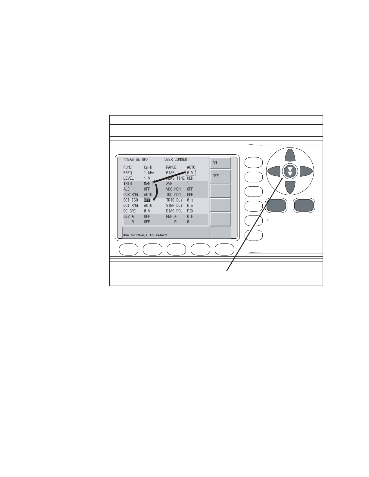
2-
㪼㪋㪐㪏㪇㪸㫌㪼㪈㪈㪌㪏
Return
㽳
㽲
㫇㫉㪼㫊㫊㩷㫋㫎㫀㪺㪼㩷㫊㫂㫀㫇㩷㫂㪼㫐
Overview
Basic Operation
How to Use Skip Keys
The following describes how to use a skip key.
On a display page, three lines are collected together as one. By using a skip
key, you can select the desired field quickly as the selected field moves from
area to area.
Figure 2-6 Skip key and a field operation example
44 Keysight E4980A/AL Precision LCR Meter
Page 45

Keysight E4980A/AL Precision LCR Meter
User’s Guide
3 Display Format
This chapter describes each page of the DISPLAY FORMAT MENU of the
E4980A/AL.
MEAS DISPLAY Page
When you press the [DISPLAY FORMAT] key, the MEAS DISPLAY page appears.
The following measurement controls can be set on this page (The field in
parenthesis is used to set measurement controls).
• Measurement Function (FUNC)
•Impedance range (RANGE)
• Test Frequency (FREQ)
• Test Signal Level (LEVEL)
• DC Bias (BIAS)
• Measurement Time Mode (MEAS TIME)
Figure 3-1 shows the available fields and the softkeys that correspond to the
fields on this page.
45
Page 46

3-
㪼㪋㪐㪏㪇㪸㫌㪼㪈㪇㪍㪉
㪑㩷㩷㪝㫀㪼㫃㪻
㪑㩷㩷㪤㫆㫅㫀㫋㫆㫉
㪤㪼㪸㫊㫌㫉㪼㫄㪼㫅㫋
㪩㪼㫊㫌㫃㫋㫊
䌻
㪼㪋㪐㪏㪇㪸㫌㫁㪈㪇㪍㪊
Display Format
MEAS DISPLAY Page
Figure 3-1 MEAS DISPLAY Page
Pressing the [DISPLAY FORMAT] key when Figure 3-1 is displayed enlarges the
measurement result as shown in Figure 3-2. Pressing the [DISPLAY FORMAT]
key again returns to the display in Figure 3-1.
Figure 3-2 The enlarged MEAS DISPLAY for measurement results
46 Keysight E4980A/AL Precision LCR Meter
Page 47

Display Format
MEAS DISPLAY Page
Measurement Function
The E4980A/AL simultaneously measures two components of the complex
impedance (parameters) in a measurement cycle.
Regardless of the types of measurement parameters, the test signal voltage
(VAC) and the test signal current (IAC) are measured at the same time. When
the E4980A/AL is equipped with option 001, the DC bias voltage level (VDC)
and the DC bias current level (IDC) are measured simultaneously.
Regardless of the types of measurement parameters, the measurement
result for the R-X parameter can be obtained using the SCPI command.
DC resistance (Rdc) can be measured when the E4980A/AL is equipped with
either option 001, 030/032, 050/052, 100/102, or 200,
DC voltage (Vdc), and DC current (Idc) can be measured when the E4980A/AL
is equipped with option 001.
Types of measurement parameters
Types of measurement parameters are shown below.
Table 3-1 Measurement parameters
Primary parameter Secondary parameter
Cp D, Q, G, Rp
Cs D, Q, Rs
Lp
Ls
RX
Z d, r
GB
Y d, r
2
Vdc
1. This parameter can be set only when the E4980A/AL is equipped with either
option 001, 030/032, 050/052, 100 or 200.
2. This parameter can be set only when the E4980A/AL is equipped with option 001.
D, Q, G, Rp, Rdc
D, Q, Rs, Rdc
2
Idc
1
1
When the measurement parameter is DC voltage measurement/DC
current measurement (Vdc-Idc), set the setting value of the test signal
level (LEVEL field) to 0 V for accurate measurement.
Keysight E4980A/AL Precision LCR Meter 47
Page 48

3-
Display Format
MEAS DISPLAY Page
Measurement parameter descriptions
The primary parameter measurement result is located on the upper line and
the secondary parameter measurement result is on the lower line in Figure 3-1
on page 46.
Each parameter is described below.
Table 3-2 Primary parameter
Parameter Description
Cp Capacitance value measured using the parallel equivalent circuit
model
Cs Capacitance value measured using the series equivalent circuit model
Lp Inductance value measured using the parallel equivalent circuit model
Ls Inductance value measured using the series equivalent circuit model
R Resistance
Z Absolute value of impedance
G Conductance
Y Absolute value of admittance
1
Vdc
1. This parameter can be set only when the E4980A/AL is equipped with option 001.
DC voltage
Table 3-3 Secondary parameter
Parameter Description
D Dissipation factor
Q Quality factor (inverse of dissipation factor)
G Conductance
Rs Equivalent series resistance measured using the series equivalent
circuit model
Rp Equivalent parallel resistance measured using the parallel equivalent
circuit model
X Reactance
B Sustenance
Phase angle
1
Idc
48 Keysight E4980A/AL Precision LCR Meter
DC current
Page 49

Display Format
MEAS DISPLAY Page
Table 3-3 Secondary parameter
Parameter Description
2
Rdc
1. This parameter can be set only when the E4980A/AL is equipped with option 001.
2. This parameter can be set only when the E4980A/AL is equipped with either
option 001, 030/032, 050/052, 100 or 200.
DC resistance
Equivalent parallel and serial combinations
The combinations of primary and secondary parameters, including the
equivalent parallel and series combinations, are listed below.
Table 3-4 Measurement function
Primary
parameter
ZZ-r
Y ----- Y-r
CCs-D
Series mode Parallel mode
Z-d
Cs-Q
Cs-Rs
-----
Y-d
Cp-D
Cp-Q
Cp-G
Cp-Rp
LLs-D
Ls-Q
Ls-Rs
Ls-Rdc
Lp-D
Lp-Q
Lp-G
Lp-Rp
Lp-Rdc
R R-X -----
G ----- G-B
Primary parameter Secondary parameter
Vdc Idc
Measurement function Vdc-Idc does not have the series mode and parallel
mode.
Keysight E4980A/AL Precision LCR Meter 49
Page 50

3-
Display Format
MEAS DISPLAY Page
Procedure for setting the measurement function
Step 1. Press the [Display Format] key.
Step 2. Press the MEAS DISPLAY softkey.
Step 3. Use the cursor keys to select the FUNC field.
Step 4. Use the softkeys to select the primary parameter.
Step 5. If the secondary parameter exists, select the secondary parameter from
measurement parameters displayed using the softkeys.
For the combinations of measurement parameters, refer to Table 3-1 on
page 47.
50 Keysight E4980A/AL Precision LCR Meter
Page 51

Display Format
MEAS DISPLAY Page
Impedance range
Impedance range mode
Two modes can be used to select the impedance range as shown in Table 3-5.
Table 3-5 Impedance range mode
Mode Function overview Ad vantage Disad vantage
Auto range
(auto selection)
Hold range
(manual selection)
The E4980A/AL sets
the optimum
impedance range for
the impedance of the
DUT.
Measurement is
performed with a fixed
impedance range
regardless of the
impedance of the
DUT.
You do not need
to select the
impedance
range.
No ranging time
is required.
The
measurement
time is longer
due to the
ranging time.
You need to
select a proper
range
depending on
the value of the
DUT.
Available impedance range
The hold range has nine impedance ranges, but when option 001 is installed, it
has ten. The impedance range is selected according to the DUT’s impedance
even if the measurement parameter is capacitance or inductance.
Model
Standard 1, 10, 100, 300, 1 k, 3 k, 10 k, 30 k, 100k
Option 001
Impedance range ()
1
100 m
, 1, 10, 100, 300, 1 k, 3k, 10 k, 30 k, 100k
1. This cannot be used when the test signal level is less than or equal to 2 V.
Keysight E4980A/AL Precision LCR Meter 51
Page 52

3-
㪼㪋㪐㪏㪇㪸㫌㪼㪈㪇㪈㪋
㪈㪇㪅㪈 㪈㪇 㪈㪇㪇 㪊㪇㪇 㪈㫂 㪊㫂 㪈㪇㫂 㪊㪇㫂 㪈㪇㪇㫂 㪈㪤 㪈㪇㪤 㪈㪇㪇㪤 㪈㪞
㪦㪭㪣㪛
㪦㪭㪣㪛
㪦㪭㪣㪛
㪦㪭㪣㪛
㪦㪭㪣㪛
㪈㪇㪇㫂㱅
㪩㪸㫅㪾㪼
㪊㪇㫂㱅
㪩㪸㫅㪾㪼
㪈㪇㫂㱅
㪩㪸㫅㪾㪼
㪊㫂㱅
㪩㪸㫅㪾㪼
㪈㫂㱅
㪩㪸㫅㪾㪼
㪊㪇㪇㱅
㪩㪸㫅㪾㪼
㪈㪇㪇㱅
㪩㪸㫅㪾㪼
㪈㪇㱅
㪩㪸㫅㪾㪼
㪈㱅
㪩㪸㫅㪾㪼
㪈㪇㪇㫄㱅
㪩㪸㫅㪾㪼
㪠㫄㫇㪼㪻㪸㫅㪺㪼
㩷㪲㱅㪴
㪑㩷㪜㪽㪽㪼㪺㫋㫀㫍㪼㩷㪤㪼㪸㫊㫌㫉㫀㫅㪾㩷㪩㪸㫅㪾㪼
㪑㩷㪛㫀㫊㫇㫃㪸㫐㪸㪹㫃㪼㩷㪩㪸㫅㪾㪼
Display Format
MEAS DISPLAY Page
Effective measurement range for each impedance range for impedance
measurement
Figure 3-3 shows the range that can be displayed and the effective measuring
range for each impedance range while in the impedance mode (| Z |, R, X). For
example, 50-k DUT impedance can be measured using the ranges of 100 k
to 30 k, but the E4980A/AL’s accuracy specification is only met when using
the 30-k range. If this DUT is measured with the 100-k range, “OVERLOAD”
will be displayed.
Figure 3-3 Effective measurement range for each impedance range (Impedance
measurement)
Table 3-6 Effective measurement range for the impedance range when it is in the HOLD
state for impedance measurement
Effective measurement range
0 < Impedance 108 m
2
108 m
< Impedance 1.08
Impedance range ()
1
100 m
1
10 1.08 < Impedance 10.08
100 10.08 < Impedance < 276
300 276 Impedance < 0.92 k
1 k 0.92 k Impedance < 2.76 k
52 Keysight E4980A/AL Precision LCR Meter
3 k 2.76 k Impedance < 9.2 k
Page 53

Display Format
MEAS DISPLAY Page
Table 3-6 Effective measurement range for the impedance range when it is in the HOLD
state for impedance measurement
Impedance range ()
10 k
30 k
Effective measurement range
9.2 k Impedance < 27.6 k
27.6 k Impedance < 92 k
3
4
100 k 92 k Impedance
1. This can be set when the test signal level is more than 2 V.
2. When the test signal level is less than or equal to 2 V or 20 mA, it is 0 (zero).
3. When test frequency is more than 100 kHz and the test signal level is less than
or equal to 0.2 V (2 mA), it is more than 9.2 k.
4. When test frequency is more than 100 kHz and the test signal level is more than
0.2 V and less than or equal to 2 V (more than 2 mA and less than or equal to 20
mA), it is more than 27.6 k.
Effective measurement range for each impedance range
The following shows the effective measurement range of each impedance
range, in which the E4980A/AL’s measurement accuracy meets its
specifications.
When the impedance range is set manually, the optimum impedance range
should be selected by matching the impedance of the DUT to the effective
measurement range shown in Figure 3-4, Figure 3-5, and Figure 3-6. When
the impedance range is set to AUTO, the optimum impedance range is
automatically selected according to the impedance of each DUT.
The impedance range is limited by the test frequency setting when the test
signal level is less than or equal to 2V. When the impedance range and
test frequency are set under the above conditions, the test frequency must
be set first, followed by the impedance range. If you set the impedance
range first and then frequency, the resulting impedance range may not be
the one you wanted to set.
Keysight E4980A/AL Precision LCR Meter 53
Page 54

3-
㪼㪋㪐㪏㪇㪸㫌㪼㪈㪇㪈㪌
㪈㪇㪇㪪
㪈㪇㪪
㪈㪞
㪈㪇㪪
㪈㪪
㪈㪇㪇㫄㪪
㪈㪇㫄㪪
㪈㫄㪪
㪈㪇㪇㱘㪪
㪈㪇㱘㪪
㪈㱘㪪
㪈㪇㪇㫅㪪
㪈㪇㫅㪪
㪈㫅㪪
㪇
㪈㪇㫄㱅
㪈㪇㪇㫄㱅
㪈㱅
㪈㪇㱅
㪈㪇㪇㱅
㪈㫂㱅
㪈㪇㫂㱅
㪈㪇㪇㫂㱅
㪈㪤㱅
㪈㪇㪤㱅
㪈㪇㪇㪤㱅
㪈㫄㱅
㪇
㪈㪞㱅
㪈㪇㫇㪝
㪈
㫅
㪝
㪈㪇㪇㫇㪝
㪈㪇㫅㪝
㪈㪇㪇㫅㪝
㪈㱘㪝
㪈㪇㱘㪝
㪈
㪇㪇㱘㪝
㪈㫄㪝
㪈
㪇㫄㪝
㪈
㪇㪇㫄㪝
㪈㪝
㪈㪇㫅㪟
㪈㫅㪟
㪈㪇㪇㫇㪟
㪈㪇㪇㫅㪟
㪈
㱘㪟
㪈㪇㱘㪟
㪈㪇㪇㱘㪟
㪈㫄㪟
㪈㪇㫄㪟
㪈㪇㪇㫄㪟
㪈㪟
㪈㪇㪟
㪈㪇㪇㪟
㪈㫇㪝
㪈㪇㪇㪽㪝
㪈㪇㪽㪝
㪈㪽㪝
㪈㪇㪇㪸
㪝
㪈㫂㪟
㪈㪇㫂㪟
㪈㪇㪇㫂㪟
㪈㪤㪟
㪉㪇 㪈㪇㪇 㪈㫂 㪈㪇㫂 㪈㪇㪇㫂 㪈㪤 㪉㪤
㪠㫅㪻㫌㪺㫋㪸㫅㪺㪼
㪚㪸㫇㪸㪺㫀㫋㪸㫅㪺㪼
㪠㫄㫇㪼㪻㪸㫅㪺㪼
㪘㪻㫄㫀㫋㫋㪸㫅㪺㪼
㪝㫉㪼㫈㫌㪼㫅㪺㫐
㪈㪇㪇㫂㱅㩷㪩㪸㫅㪾㪼
㪊㪇㫂㱅㩷㪩㪸㫅㪾㪼
㪈㪇㫂㱅㩷㪩㪸㫅㪾㪼
㪊㫂㱅㩷㪩㪸㫅㪾㪼
㪈㫂㱅㩷㪩㪸㫅㪾㪼
㪊㪇㪇㱅㩷㪩㪸㫅㪾㪼
㪈㪇㪇㱅㩷㪩㪸㫅㪾㪼
㪈㪇㱅㩷㪩㪸㫅㪾㪼
㪈㪇㱅㩷㪩㪸㫅㪾㪼
Display Format
MEAS DISPLAY Page
Figure 3-4 Effective measurement range (0.2V or 2 mA < Test signal level 2 V or 20 mA)
54 Keysight E4980A/AL Precision LCR Meter
Page 55

Display Format
㪼㪋㪐㪏㪇㪸㫌㪼㪈㪇㪈㪍
㪈㪇㪇㪪
㪈㪇㪪
㪈㪞
㪈㪇㪪
㪈㪪
㪈㪇㪇㫄㪪
㪈㪇㫄㪪
㪈㫄㪪
㪈㪇㪇㱘㪪
㪈㪇㱘㪪
㪈㱘㪪
㪈㪇㪇㫅㪪
㪈㪇㫅㪪
㪈㫅㪪
㪇
㪈㪇㫄㱅
㪈㪇㪇㫄㱅
㪈㱅
㪈㪇㱅
㪈㪇㪇㱅
㪈㫂㱅
㪈㪇㫂㱅
㪈㪇㪇㫂㱅
㪈㪤㱅
㪈㪇㪤㱅
㪈㪇㪇㪤㱅
㪈㫄㱅
㪇
㪈㪞㱅
㪈㪇㫇㪝
㪈
㫅㪝
㪈㪇㪇㫇㪝
㪈㪇㫅㪝
㪈㪇㪇㫅㪝
㪈㱘㪝
㪈
㪇㱘㪝
㪈
㪇
㪇㱘㪝
㪈㫄㪝
㪈㪇㫄㪝
㪈㪇
㪇㫄㪝
㪈㪝
㪈㪇㫅㪟
㪈㫅㪟
㪈㪇㪇㫇㪟
㪈㪇㪇㫅㪟
㪈㱘㪟
㪈㪇㱘㪟
㪈㪇㪇㱘
㪟
㪈㫄
㪟
㪈㪇㫄㪟
㪈㪇㪇㫄㪟
㪈㪟
㪈㪇㪟
㪈㪇㪇㪟
㪈㫇㪝
㪈㪇㪇㪽㪝
㪈㪇㪽㪝
㪈㪽㪝
㪈㪇㪇㪸㪝
㪈㫂㪟
㪈㪇㫂㪟
㪈㪇㪇㫂㪟
㪈㪤㪟
㪉㪇 㪈㪇㪇 㪈㫂 㪈㪇㫂 㪈㪇㪇㫂 㪈㪤 㪉㪤
㪠㫅㪻㫌㪺㫋㪸㫅㪺㪼
㪚㪸㫇㪸㪺㫀㫋㪸㫅㪺㪼
㪠㫄㫇㪼㪻㪸㫅㪺㪼
㪘㪻㫄㫀㫋㫋㪸㫅㪺㪼
㪝㫉㪼㫈㫌㪼㫅㪺㫐
㪈㪇㪇㫂㱅㩷㪩㪸㫅㪾㪼
㪊㪇㫂㱅㩷㪩㪸㫅㪾㪼
㪈㪇㫂㱅㩷㪩㪸㫅㪾㪼
㪊㫂㱅㩷㪩㪸㫅㪾㪼
㪈㫂㱅㩷㪩㪸㫅㪾㪼
㪊㪇㪇㱅㩷㪩㪸㫅㪾㪼
㪈㪇㪇㱅㩷㪩㪸㫅㪾㪼
㪈㪇㱅㩷㪩㪸㫅㪾㪼
㪈㪇㪇㫄㱅㩷㪩㪸㫅㪾㪼
㪈㪇㱅㩷㪩㪸㫅㪾㪼
MEAS DISPLAY Page
Figure 3-5 Effective measurement range (Test signal level > 2 V or 20 mA)
Keysight E4980A/AL Precision LCR Meter 55
Page 56

3-
㪼㪋㪐㪏㪇㪸㫌㪼㪈㪈㪍㪌
㪈㪇㪇㪪
㪈㪇㪪
㪈㪞
㪈㪇㪪
㪈㪪
㪈㪇㪇㫄㪪
㪈㪇㫄㪪
㪈㫄㪪
㪈㪇㪇㱘㪪
㪈㪇㱘㪪
㪈㱘㪪
㪈㪇㪇㫅㪪
㪈㪇㫅㪪
㪈㫅㪪
㪇
㪈㪇㫄㱅
㪈㪇㪇㫄㱅
㪈㱅
㪈㪇㱅
㪈㪇㪇㱅
㪈㫂㱅
㪈㪇㫂㱅
㪈㪇㪇㫂㱅
㪈㪤㱅
㪈㪇㪤㱅
㪈㪇㪇㪤㱅
㪈㫄㱅
㪇
㪈㪞㱅
㪈㪇㫇㪝
㪈
㫅
㪝
㪈㪇㪇㫇㪝
㪈㪇㫅㪝
㪈㪇㪇㫅㪝
㪈㱘㪝
㪈㪇㱘㪝
㪈
㪇㪇㱘㪝
㪈㫄㪝
㪈
㪇㫄㪝
㪈
㪇㪇㫄㪝
㪈㪝
㪈㪇㫅㪟
㪈㫅㪟
㪈㪇㪇㫇㪟
㪈㪇㪇㫅㪟
㪈
㱘㪟
㪈㪇㱘㪟
㪈㪇㪇㱘㪟
㪈㫄㪟
㪈㪇㫄㪟
㪈㪇㪇㫄㪟
㪈㪟
㪈㪇㪟
㪈㪇㪇㪟
㪈㫇㪝
㪈㪇㪇㪽㪝
㪈㪇㪽㪝
㪈㪽㪝
㪈㪇㪇㪸
㪝
㪈㫂㪟
㪈㪇㫂㪟
㪈㪇㪇㫂㪟
㪈㪤㪟
㪉㪇 㪈㪇㪇 㪈㫂 㪈㪇㫂 㪈㪇㪇㫂 㪈㪤 㪉㪤
㪠㫅㪻㫌㪺㫋㪸㫅㪺㪼
㪚㪸㫇㪸㪺㫀㫋㪸㫅㪺㪼
㪠㫄㫇㪼㪻㪸㫅㪺㪼
㪘㪻㫄㫀㫋㫋㪸㫅㪺㪼
㪝㫉㪼㫈㫌㪼㫅㪺㫐
㪈㪇㪇㫂㱅㩷㪩㪸㫅㪾㪼
㪊㪇㫂㱅㩷㪩㪸㫅㪾㪼
㪈㪇㫂㱅㩷㪩㪸㫅㪾㪼
㪊㫂㱅㩷㪩㪸㫅㪾㪼
㪈㫂㱅㩷㪩㪸㫅㪾㪼
㪊㪇㪇㱅㩷㪩㪸㫅㪾㪼
㪈㪇㪇㱅㩷㪩㪸㫅㪾㪼
㪈㪇㱅㩷㪩㪸㫅㪾㪼
㪈㪇㱅㩷㪩㪸㫅㪾㪼
Display Format
MEAS DISPLAY Page
Figure 3-6 Effective measurement range (Test signal level 0.2 V or 2 mA)
56 Keysight E4980A/AL Precision LCR Meter
Page 57

Display Format
MEAS DISPLAY Page
Procedure for setting the impedance range
Step 1. Press the [Display Format] key.
Step 2. Press the MEAS DISPLAY softkey.
Step 3. Use the cursor keys to select the RANGE field.
Step 4. Use the softkeys to select the impedance range mode or impedance range.
Softkey Function
AUTO Sets the impedance range mode to AUTO.
HOLD Sets the impedance range mode to HOLD.
INCR + Increments the impedance range in the HOLD mode.
DECR - Decrements the impedance range in the HOLD mode.
Manually setting the time for the impedance range mode
Changing impedance range requires a few milliseconds to several tens of
milliseconds. For details, refer to Settling Time in data sheet in Chapter 11
“Specifications and Supplemental Information”
Keysight E4980A/AL Precision LCR Meter 57
Page 58

3-
Display Format
MEAS DISPLAY Page
Test Frequency
Test frequency point
The E4980A/AL’s test frequency can be set in the range from 20 Hz to 2 MHz.
The last digit of the four-digit test frequency display (including digits after the
decimal point) can be set as the resolution.
Table 3-7 shows the test frequency point of each frequency range (F).
Table 3-7 Frequency range and test frequency point
Frequency range (F) Test frequency point Resolutio
n
20 Hz F 99.99 Hz 20.00 Hz, 20.01 Hz•••99.99 Hz 0.01 Hz
100 Hz F 999.9 Hz 100.0 Hz, 100.1 Hz•••999.9 Hz 0.1 Hz
1 kHz F 9.999 kHz 1.000 kHz, 1.001 kHz•••9.999 kHz 1 Hz
10 kHz F 99.99 kHz 10.00 kHz, 10.01 kHz•••99.99 kHz 10 Hz
100 kHz F 999.9 kHz 100.0 kHz, 100.1 kHz•••999.9 kHz 100 Hz
1 MHz F 2 MHz 1.000 MHz, 1.001 MHz•••2.000 MHz 1 kHz
When more than five-digit numeric data (including digits after the decimal
point) are entered, the nearest test frequency point is automatically set.
Procedure for setting test frequency
Step 1. Press the [Display Format] key.
Step 2. Use the cursor keys to select the FREQ field.
Step 3. Use the softkeys or numeric entry keys to enter the test frequency. When
data is entered with the numeric entry keys, the softkeys change to unit
labels (Hz, kHz, MHz).
Softkey Function
INCR ++ Increments the test frequency to the next sequentially higher tenfold
value after 20 Hz. Refer to Table 3-8 for the test frequency points
that can be set using this softkey.
INCR + Increments the current test frequency to the next sequentially
higher frequency point. There are ten frequency points between
successive decade values. Refer to Table 3-9 for the sequential
frequency points that can be set using this softkey.
58 Keysight E4980A/AL Precision LCR Meter
Page 59

Display Format
MEAS DISPLAY Page
Softkey Function
DECR - Decreases the test frequency to the next sequentially lower
frequency point. There are ten frequency points between successive
decade values. Refer to Table 3-9 for the frequency points that can
be set using this softkey.
DECR -- Decreases the test frequency to the next sequentially lower tenth
value after 20 Hz. Refer to Table 3-8 for the frequency points that
can be set using this softkey.
Table 3-8 Test frequency that can be set using INCR ++ / DECR --
INCR ++ / DECR --
20 Hz
100 Hz
1 kHz
10 kHz
100 kHz
1 MHz
2 MHz
Table 3-9 Test frequency that can be set using INCR + / DECR -
INCR + / DECR -
20 Hz 100 Hz 1 kHz 10 kHz 100 kHz 1 MHz
25 Hz 120 Hz 1.2 kHz 12 kHz 120 kHz 1.2 MHz
30 Hz 150 Hz 1.5 kHz 15 kHz 150 kHz 1.5 MHz
40 Hz 200 Hz 2 kHz 20 kHz 200 kHz 2 MHz
50 Hz 250 Hz 2.5 kHz 25 kHz 250 kHz
60 Hz 300 Hz 3 kHz 30 kHz 300 kHz
80 Hz 400 Hz 4 kHz 40 kHz 400 kHz
500 Hz 5 kHz 50 kHz 500 kHz
600 Hz 6 kHz 60 kHz 600 kHz
800 Hz 8 kHz 80 kHz 800 kHz
Keysight E4980A/AL Precision LCR Meter 59
Page 60

3-
Display Format
MEAS DISPLAY Page
Time required for setting the test frequency
Changing the test frequency requires a few milliseconds to several tens of
milliseconds. For details, refer to Settling Time in data sheet in Chapter 11
“Specifications and Supplemental Information”
60 Keysight E4980A/AL Precision LCR Meter
Page 61

Display Format
MEAS DISPLAY Page
Test Signal Level
The E4980A/AL’s test signal level can be set as the effective value (RMS value)
of a sine wave of the test frequency from the unit’s internal oscillator. You can
set either the oscillator voltage level or the oscillator current level. The output
impedance is 100 .
The set value of the oscillator current level is the value set when the
measurement contacts (UNKNOWN terminals) are shorted together.
The set value of the oscillator voltage level is the value set when the
measurement contacts (UNKNOWN terminals) are opened.
The E4980A/AL can measure a device using a constant voltage or current level
by using the automatic level control function. (The automatic level control
function (ALC field) can be set to ON from the MEAS SETUP page.) When a
constant voltage or current level measurement is performed, an asterisk mark
(*) appears at the end of the LEVEL display. For more information about the
automatic level control function, refer to “Automatic level control” on page 93.
Test signal level and resolution (Standard)
When option 001 (power/DC bias enhance) is not installed, the oscillator
voltage level can be set with a resolution listed in Table 3-10, or the oscillator
current level can be set with a resolution listed in Table 3-11.
Table 3-10 Oscillator voltage level and resolution (Std.)
Oscillator voltage level Resolution
0 Vrms to 200 mVrms 100 Vrms
200 mVrms to 500 mVrms 200 Vrms
500 mVrms to 1 Vrms 500 Vrms
1 Vrms to 2 Vrms 1 mVrms
Table 3-11 Oscillator current level and resolution (Std.)
Oscillator current level Resolution
0 Arms to 2 mArms 1 Arms
2 mArms to 5 mArms 2 Arms
5 mArms to 10 mArms 5 Arms
10 mArms to 20 mArms 10 Arms
Keysight E4980A/AL Precision LCR Meter 61
Page 62

3-
Display Format
MEAS DISPLAY Page
Test signal level and resolution (Option 001)
When option 001 (power/DC bias enhance) is installed, the oscillator voltage
level can be set with a resolution listed in Table 3-12, or the oscillator current
level can be set with a resolution listed in Table 3-13.
Table 3-12 Oscillator voltage level and resolution (Option 001)
Oscillator voltage level Resolution
0 Vrms to 200 mVrms 100 Vrms
200 mVrms to 500 mVrms 200 Vrms
500 mVrms to 1 Vrms 500 Vrms
1 Vrms to 2 Vrms 1 mVrms
2 Vrms to 5 Vrms 2 mVrms
5 Vrms to 10 Vrms 5 mVrms
10 Vrms to 20 Vrms
1. When the test frequency is more than 1 MHz, the maximum oscillator voltage
level that can be set is 15 Vrms.
1
10 mVrms
Table 3-13 Oscillator current level and resolution (Option 001)
Oscillator current level Resolution
0 Arms to 2 mArms 1 Arms
2 mArms to 5 mArms 2 Arms
5 mArms to 10 mArms 5 Arms
10 mArms to 20 mArms 10 Arms
20 mArms to 50 mArms 20 Arms
50 mArms to 100 mArms 50 Arms
Test signal level setting procedure
Step 1. Press the [Display Format] key
Step 2. Press the MEAS DISPLAY softkey.
Step 3. Use the cursor keys to select the LEVEL field.
62 Keysight E4980A/AL Precision LCR Meter
Page 63

Display Format
MEAS DISPLAY Page
Step 4. Use the softkeys or numeric entry keys to enter the test signal level. When
data is entered with the numeric entry keys, the softkeys change to units
labels (mV, V, uA, mA, A).
Softkey Function
INCR ++ Increases the oscillator’s output level with a resolution shown in
Table 3-14 or Table 3-15.
INCR + Increases the oscillator’s output level with a resolution shown in
Table 3-10 to Table 3-13.
DECR - Decreases the oscillator’s output level with a resolution shown in
Table 3-10 to Table 3-13.
DECR -- Decreases the oscillator’s output level with a resolution shown in
Table 3-14 or Table 3-15.
Table 3-14 Oscillator’s voltage level that can be set with INCR ++ / DECR --
INCR ++ / DECR -- (Vrms)
0,
1 m, 2 m, 3 m, •••, 9 m
10 m, 20 m, 30 m, •••, 90 m
100 m, 200 m, 300 m, •••, 900 m
1, 2, 3, •••, 9
10, 20
1. The voltage level can be set to more than 2 V only when option 001
1
1
is installed.
Table 3-15 Oscillator’s current level that can be set with INCR ++ / DECR --
INCR ++ / DECR -- (Arms)
0,
10 , 20 , 30 , •••, 90
100 , 200 , 300 , •••, 900
1 m, 2 m, 3 m, •••, 9 m
10 m, 20 m, 30 m, •••, 90 m
1
100 m
1. The current level can be set to more than 20 m only when option
001 is installed.
Keysight E4980A/AL Precision LCR Meter 63
1
Page 64

3-
Display Format
MEAS DISPLAY Page
DC Bias
The E4980A/AL has an internal DC bias. A DC bias is output when the DC Bias
key on the front panel is set to ON.
The DC Bias key is a toggle-type switch used to enable DC bias output. When
you press the DC Bias key, DCBIAS appears in the status display area and the
LED indicator for DC bias is ON (orange). When you press the DC Bias key
again, DCBIAS disappears from the status display area and the LED indicator is
OFF. If the DC Bias key is set to OFF, the setting value for the DC bias is not
output even though the DC bias is set to ON in the BIAS field.
The setting value of the DC bias signal voltage is the value set when the
measurement contacts (UNKNOWN terminals) are opened.
The setting value of the DC bias signal current is the value set when the
measurement contacts (UNKNOWN terminals) are shorted.
The range of the DC bias has two types: AUTO and FIX. When the E4980A/AL is
initiated or preset, AUTO is set. The following descriptions are effective when
AUTO is set as a range. Use the SCPI command to fix the range. For details,
refer to “:BIAS:RANGe:AUTO” on page 323.
DC bias (Standard)
When option 001 (power/DC bias enhance) is not installed, the DC bias can be
set with a resolution listed in Table 3-16. The level of the DC bias signal current
cannot be set without option 001 present.
Table 3-16 DC bias and resolution (Std.)
DC bias signal voltage DC bias signal current
0 V, 1.5 V, 2.0 V unavailable
DC bias and resolution (Option 001)
When option 001 (power/DC bias enhance) is installed, the DC bias signal
voltage and signal current can be set with a resolution listed in Table 3-17 or
Table 3-18.
Table 3-17 DC bias and resolution (Option 001)
DC bias signal voltage level Resolution
(0 V to 5 V)
(5 V to 10 V) 1 mV
100 V
1
(10 V to 20 V) 2 mV
(20 V to 40 V) 5 mV
1. Effective resolution is 330 V.
64 Keysight E4980A/AL Precision LCR Meter
Page 65

Display Format
㪼㪋㪐㪏㪇㪸㫌㪼㪈㪇㪈㪎
㪈㪇㪇㱅
㪟㪠㪞㪟 㪣㪦㪮
㪛㪚㩷㪙㪠㪘㪪
㪚㪬㪩㪩㪜㪥㪫
㪪㪿㫆㫉㫋㪼㪻
MEAS DISPLAY Page
Table 3-18 DC bias and resolution (Option 001)
DC bias signal current level Resolution
(0A to 50 mA)
(50 mA to 100 mA) 10 A
1. Effective resolution is 3.3 A.
When a DUT is connected to the measurement contacts, the setting current
value is different from the actual current passing through the DUT. For normal
measurement taken by applying the signal current through a device, refer to
“DC Bias Current Isolation” on page 97.
Figure 3-7 DC bias signal current
1 A
1
Setting limits for DC bias and test signal level
When both the DC bias and the test signal level are set under the following
conditions, the amount of DC bias plus the test signal level is limited to the
values listed in Table 3-19
• Option 001 is installed.
• The DC Bias key on the front panel is set to ON.
Table 3-19 DC bias and test signal level-setting limits
Setting value Limit
DC bias Test signal
Vdc (V) Vosc (Vrms) Vosc 2 1.15 + Vdc 1.002 < 42 V
Vdc (V) Iosc (Arms) Iosc 2 115 + Vdc 1.002 < 42 V
Keysight E4980A/AL Precision LCR Meter 65
level
Page 66

3-
Display Format
MEAS DISPLAY Page
Table 3-19 DC bias and test signal level-setting limits
Setting value Limit
DC bias Test signal
level
Idc (A) Vosc(Vrms) Vosc 2 1.15 + Idc 100.2 < 42 V
Idc (A) Iosc (Arms) Iosc 2 115 + Idc 100.2 < 42 V
Procedure for setting DC bias
Step 1. Press the [Display Format] key.
Step 2. Press the MEAS DISPLAY softkey.
Step 3. Use the cursor keys to select the BIAS field.
Step 4. Use the softkeys or numeric entry keys to enter the test signal level. When
data is entered with the numeric entry keys, the softkey labels are changed to
the appropriate unit labels (mV, V, uA, mA, A).
Softkey Function
INCR ++ Increases the oscillator’s output level with a resolution shown in
Table 3-20 or Table 3-21.
INCR + Increases the oscillator’s output level with a resolution shown in
Table 3-16 to Table 3-18.
DECR - Decreases the oscillator’s output level with a resolution shown in
Table 3-16 to Table 3-18.
DECR -- Decreases the oscillator’s output level with a resolution shown in
Table 3-20 or Table 3-21.
Table 3-20 DC bias signal voltage that can be set with INCR ++ / DECR --
INCR ++ / DECR -- (V)
1
0,
100 , 200 , 300 , •••, 900
1 m, 2 m, 3 m, •••, 9 m
10 m, 20 m, 30 m, •••, 90 m
100 m, 200 m, 300 m, •••, 900 m
1, 2, 3, •••, 9
10, 20, 30, 40
66 Keysight E4980A/AL Precision LCR Meter
Page 67

Display Format
MEAS DISPLAY Page
1. When option 001 is not installed, only 0 V, 1.5 V, and 2.0 V can be
set.
Table 3-21 DC bias signal current that can be set with INCR ++ / DECR
INCR ++ / DECR -- (A)
1
0,
1 , 2 , 3 , •••, 9
10 , 20 , 30 , •••, 90
100 , 200 , 300 , •••, 900
1 m, 2 m, 3 m, •••, 9 m
10 m, 20 m, 30 m, •••, 90 m
100 m
1. This cannot be set when option 001 is not installed.
Step 5. Press [DC Bias] to set the DC bias output to ON. DCBIAS appears in the status
display area and the LED indicator for DC bias lights up in orange.
Settling time for the DC bias signal voltage
Changing the DC bias requires a few milliseconds to several tens of
milliseconds. For details, refer to DC bias settling time in data sheet in Chapter
11 “Specifications and Supplemental Information”
Keysight E4980A/AL Precision LCR Meter 67
Page 68

3-
Display Format
MEAS DISPLAY Page
Measurement Time Mode
Three measurement time modes (SHORT, MEDIUM, LONG) can be selected for
the E4980A/AL. A longer measurement time will result in more stable and
accurate measurement results. Refer to “Measurement time” on page 442 For
details on the measurement time of each measurement time mode.
Procedure for setting measurement time mode
Step 1. Press the [Display Format] key.
Step 2. Press the MEAS DISPLAY softkey.
Step 3. Use the cursor keys to select the MEAS TIME field.
Step 4. Use the softkeys to set the measurement time.
Softkey Function
SHORT Shortens the measurement time
MED Sets the measurement time between SHORT and LONG
LONG Lengthens the measurement time
68 Keysight E4980A/AL Precision LCR Meter
Page 69

Display Format
MEAS DISPLAY Page
Display Setting for Measurement Results
The E4980A/AL can set the display digits and display units for measurement
results (primary parameter/secondary parameter). For measurement
parameters whose “setting available?” column is No in Table 3-22, the display
setting cannot be changed. For measurement parameters whose display digit
can be set to AUTO or FIXED, generally AUTO is selected. Regarding the
display range for measurement values, refer to “Measurement display ranges”
in data sheet in Chapter 11 “Specifications and Supplemental Information”
Table 3-22 shows the digits and units that can be set for each measurement
parameter.
Under certain conditions, a message will be displayed instead of measurement
results. For details, refer to “Displaying Errors instead of Measurement
Results” on page 71
Table 3-22 Display Settings for Measurement Results
Measurement
Parameter
Unit Setting
available
Display
digits
Supplementary unit Minimum
display
Maximum
display
?
Vdc V Yes AUTO/FIX a,f,p,n,u,m,k,M,G,T,P,E 1.000000a 999.9999E
Idc A Yes AUTO/FIX a,f,p,n,u,m,k,M,G,T,P,E 1.000000a 999.9999E
R,X,Z,Rdc Yes AUTO/FIX a,f,p,n,u,m,k,M,G,T,P,E 1.000000a 999.9999E
G,B,Y S Yes AUTO/FIX a,f,p,n,u,m,k,M,G,T,P,E 1.000000a 999.9999E
Cp,Cs F Yes AUTO/FIX a,f,p,n,u,m,k,M,G,T,P,E 1.000000a 999.9999E
Lp,Ls H Yes AUTO/FIX a,f,p,n,u,m,k,M,G,T,P,E 1.000000a 999.9999E
-rad rad Yes AUTO/FIX a,f,p,n,u,m,k,M,G,T,P,E 1.000000a 3.141593
Dn.a.NoFIXn.a. 0.000001 9.999999
Qn.a.NoFIXn.a. 0.01 99999.99
-deg deg No FIX n.a. 0.0001 180.0000
%%NoFIXn.a. 0.0001 999.9999
Procedure to change display setting
Step 1. Press the [Display Format] key.
Step 2. Press the MEAS DISPLAY softkey.
Step 3. Use the cursor keys to select the field in which a measurement result of
primary parameter or secondary parameter is displayed.
Step 4. Use the following softkeys to set the display.
Keysight E4980A/AL Precision LCR Meter 69
Page 70

3-
㪼㪋㪐㪏㪇㪸㫌㫁㪈㪈㪍㪈
Display Format
MEAS DISPLAY Page
Softkey Function
D.P. AUTO Automatically displays the appropriate digits and units
D.P FIX Displays measurement data using a fixed-point display format. In
this case, is displayed at the fixed decimal point. (refer to
Figure 3-8).
D.P POS INCR + Moves the decimal point to the left. Supplementary units are also
changed.
D.P POS DECL - Moves the decimal point to the right. Supplementary units are also
changed.
Figure 3-8 Fixed-display sample of a measurement result
70 Keysight E4980A/AL Precision LCR Meter
Page 71

Display Format
MEAS DISPLAY Page
Displaying Errors instead of Measurement Results
Under certain conditions, the following message will appear instead of the
measurement results. A description of each message is provided below.
Error messages
Message Description
OVERLOAD This message appears when overload occurs. The returned value is
“9.9E37” when using the SCPI command. Conditions in which
overload occurs differ depending on the impedance range
settings. For details, refer to Table 3-26 on page 74.
--- This appears when no measurement was performed, or the
measurement result is beyond the display range.
INFINITY This message appears when the deviation mode of the deviation
measurement function is % and the measurement result cannot be
calculated.
Conditions where overload occurs for impedance measurement
Conditions differ depending on the impedance range setting (RANGE field).
Impedance
range
AUTO • E4980A/AL’s internal detector detects overload
HOLD Conditions differ depending on the impedance range. Refer to Table
Table 3-23 Overload range when the impedance range is in the HOLD state for
impedance measurement
Impedance range
( ) (RANGE field)
0.1 0 to 0.11 more than 0.11
1 0 to 1.1 more than 1.1
Conditions
• When the DUT’s distortion is large
• When the DUT’s response is slow
3-23
Measurable range Range in which overload occurs
10 0 to 11 more than 11
100 0 or more n.a.
300 270 or more less than 270
1 k 900 or more less than 900
Keysight E4980A/AL Precision LCR Meter 71
Page 72

3-
Display Format
MEAS DISPLAY Page
Table 3-23 Overload range when the impedance range is in the HOLD state for
impedance measurement
Impedance range
Measurable range Range in which overload occurs
( ) (RANGE field)
3 k 2700 or more less than 2700
10 k 9,000 or more less than 9,000
30 k 27,000 or more less than 27,000
100 k 90,000 or more less than 90,000
Conditions where overload occurs for DCR measurement
Conditions differ depending on the DCR impedance-range setting (DCR RNG
field).
Impedance
range
AUTO When the E4980A/AL’s internal detector detects overload
HOLD Conditions differ depending on the impedance range. Refer to Table
Table 3-24 Overload range when the impedance range is in the HOLD state for DCR
measurement
Conditions
3-24
Impedance range ( )
(DCR RNG field)
Measurable range Range in which overload
occurs
10 0 to 11 more than 11
100 0 or more n.a.
1 k 900 or more less than 900
10 k 9,000 or more less than 9,000
100 k 90,000 or more less than 90,000
72 Keysight E4980A/AL Precision LCR Meter
Page 73

Display Format
MEAS DISPLAY Page
Conditions in which overload occurs for Vdc-Idc measurement (DC
source-level monitor)
Conditions differ depending on the Idc impedance range setting (DCI RNG
field).
Impedance
range
AUTO • When the measurement value exceeds 125 mA
HOLD Conditions differ depending on the impedance range. Refer to Table
Overload does not occur for Vdc measurement.
Table 3-25 Overload range when the impedance range is in the HOLD state for Idc
measurement
Impedance range (A)
(DCI RNG field)
20 0 to 22 more than 22
200 0 to 220 more than 220
2 m 0 to 2.2 m more than 2.2 m
Conditions
• When the E4980A/AL’s internal detector detects overload
3-25
Measurable range Range inn which overload
occurs
20 m 0 to 22 m more than 22 m
100 m 0 to 110 m more than 110 m
List of measurement results when overload occurs.
This section describes measurement results and each monitor value when
overload occurs.
The bold font in the list indicates the measurement parameter for which
overload occurs.
“*” indicates that measurement results, judgment, and BIN count are normal.
Keysight E4980A/AL Precision LCR Meter 73
Page 74

3-
Display Format
MEAS DISPLAY Page
Table 3-26 List of measurement results when overload occurs
Measurement
parameter
Meas.
value
Meas. val ue
(second ary)
VAC/IAC
monitor
VDC
monitor
IDC
monitor
IN/
OUT
BIN
No.
(primary)
Impedance
OVLD OVLD --- --- --- L OUT
measurement (except
for Ls/Lp-Rdc)
Impedance
OVLD OVLD --- --- --- L OUT
measurement (except
for Ls/Lp-Rdc)
Impedance
OVLD --- --- --- --- L OUT
measurement
(Ls/Lp-Rdc)
DCR measurement
* OVLD ***LOUT
(Ls/Lp-Rdc)
Vdc-Idc measurement * OVLD 0*OVLDLOUT
Other than Vdc-Idc
***OVLD --- * *
measurement
Other than Vdc-Idc
****OVLD **
measurement
OVLD is displayed as OVERLOAD on the display.
74 Keysight E4980A/AL Precision LCR Meter
Page 75

Display Format
MEAS DISPLAY Page
Monitor Information
The following describes monitor information displayed on the MEAS DISPLAY
page. This information cannot be changed on the MEAS DISPLAY page.
Monitor
Description
information
VAC Displays the test signal voltage level (AC voltage). Displays
measurement results regardless of the type of measurement
parameter
IAC Displays the test signal current level (AC current). Displays
measurement results regardless of the type of measurement
parameter
VDC Displays the DC bias voltage level (DC voltage). Set the VDC MON
field of the [Means Setup] page to ON when you want to display it.
1
IDC Displays the DC bias current level (DC current). Set the IDC MON field
of the [Means Setup] page to ON when you want to display it
CORR Displays the correction information of enabled correction types
(OPEN/SHORT/LOAD) and cable length
CH
1. This can be displayed only when option 001 is installed.
2. SINGLE is displayed when option 301 is not installed.
Displays the channel number in the multi-correction mode
2
The VDC/IDC monitor values are the ones measured under the condition
that the setting value of the test signal level (LEVEL field) is output.
Therefore, these values are different from the measurement results
displayed when the measurement parameter is DC voltage
measurement/DC current measurement (Vdc-Idc).
Keysight E4980A/AL Precision LCR Meter 75
Page 76

3-
Display Format
BIN NO. DISPLAY Page
BIN NO. DISPLAY Page
When you press the [Display Format] key and BIN No. soft key, the BIN No.
DISPLAY page appears. The bin sorting results are displayed in large
characters while the measurement results are shown in normal characters. The
following measurement controls can be set from the BIN No. DISPLAY page
(The field in parenthesis is used when this control is set).
• Comparator function ON/OFF (COMP field)
This page also provides the following information in the monitor areas (each
monitor area looks like a field but is not). These conditions can be set from the
MEAS SETUP page and the CORRECTION page, and most conditions can be
set from the MEAS DISPLAY page.
• Measurement Function (FUNC)
•Impedance range (RANGE)
• Test Frequency (FREQ)
• Test Signal Level (LEVEL)
• DC Bias (BIAS)
• Measurement Time Mode (MEAS TIME)
• Correction Information (CORR)
Figure 3-9 shows the available fields and the softkeys that correspond to each
field on this page.
76 Keysight E4980A/AL Precision LCR Meter
Page 77

Display Format
㪼㪋㪐㪏㪇㪸㫌㪼㪈㪇㪍㪋
㪑㩷㩷㪝㫀㪼㫃㪻
㪑㩷㩷㪤㫆㫅㫀㫋㫆㫉
㪙㪠㪥㩷㪪㫆㫉㫋㫀㫅㪾
㪩㪼㫊㫌㫃㫋㫊
㪤㪼㪸㫊㫌㫉㪼㫄㪼㫅㫋
㪩㪼㫊㫌㫃㫋㫊
BIN NO. DISPLAY Page
Figure 3-9 BIN NO. DISPLAY page
Comparator Function ON/OFF
The E4980A/AL’s built-in comparator can sort devices into a maximum of ten
bins (BIN 1 to BIN 9 and the OUT OF BIN) using a maximum of nine pairs of
primary parameter limits and one pair of secondary parameter limits. Also, a
device whose primary parameter is within limits, but whose secondary
parameter measurement result is not, can be sorted into an auxiliary BIN (AUX
BIN). To control a component handler using the comparator function, it is
necessary to install option 201.
These limits settings for bin sorting are set on the LIMIT TABLE page from the
[MEAS SETUP] key (refer to Chapter 4). Therefore, this COMP field allows you
to only set the comparator function to ON or OFF.
Procedure for setting the comparator function
Step 1. Press the [Display Format] key.
Step 2. Press the BIN No. softkey.
Step 3. Use the cursor keys to select the COMP field.
Keysight E4980A/AL Precision LCR Meter 77
Page 78

3-
Display Format
BIN NO. DISPLAY Page
Step 4. Use the softkeys to set the comparator function to ON or OFF.
Softkey Function
ON Sets the comparator to ON
OFF Sets the comparator to OFF
78 Keysight E4980A/AL Precision LCR Meter
Page 79

Display Format
BIN COUNT DISPLAY Page
BIN COUNT DISPLAY Page
When you press the [Display Format] key and BIN COUNT softkey, the BIN
COUNT DISPLAY page is displayed. On this page, the comparator’s count
results are displayed (The field in parentheses is used for setting).
• Counter function ON/OFF (COUNT field)
This page also provides the following information in the monitor areas (each
monitor area looks like a field, but is not). These conditions can be set from the
LIMIT TABLE SETUP page. For more details, refer to “LIMIT TABLE SETUP
Page” on page 130.
• Measurement Function (FUNC)
• Nominal Value (NOM)
• Test Frequency (FREQ)
• Bin Sorting Low/High Limits (LOW/HIGH)
• BIN Sorting Results (RESULT)
Figure 3-10 shows the available fields and the softkeys that correspond to
each field on this page.
You can set it so that a beep sounds when the sorting result is output. For
details, refer to “Beep Feature” on page 139.
Keysight E4980A/AL Precision LCR Meter 79
Page 80

3-
㪑㩷㩷㪝㫀㪼㫃㪻
㪑㩷㩷㪤㫆㫅㫀㫋㫆㫉
Display Format
BIN COUNT DISPLAY Page
Figure 3-10 BIN COUNT DISPLAY Page
㪼㪋㪐㪏㪇㪸㫌㪼㪈㪇㪍㪌
80 Keysight E4980A/AL Precision LCR Meter
Page 81

Display Format
BIN COUNT DISPLAY Page
Counter Function
The E4980A/AL is capable of counting bins. The number of devices sorted into
each bin is counted while the unit sorts the devices into appropriate bins using
the comparator function.
The maximum count is 999,999. The counting operation stops and the overflow
message “----” appears when this value is reached.
Counter setting procedure
Step 1. Press the [Display Format] key.
Step 2. Press the BIN COUNT softkey.
Step 3. Use the cursor keys to select the COUNT field.
Step 4. Use the softkeys to set the counter to ON/OFF.
Softkey Function
COUNT ON Sets the counter to ON
COUNT OFF Sets the counter to OFF
Counter reset procedure
Step 1. Press the [Display Format] key.
Step 2. Press the BIN COUNT softkey.
Step 3. Use the cursor keys to select the COUNT field.
Step 4. Use the softkeys to press RESET COUNT.
The counter is reset when the instrument setting state is recalled.
Keysight E4980A/AL Precision LCR Meter 81
Page 82

3-
Display Format
LIST SWEEP DISPLAY Page
LIST SWEEP DISPLAY Page
When you press the [Display Format] key and LIST SWEEP softkey, the LIST
SWEEP DISPLAY page appears. On this page in is possible to enter sweep
points and measurement limits of up to 201 frequencies, test signal levels, DC
bias, or DC source. The sweep points are automatically swept and the
measurement results are compared to the limits.
On the LIST SWEEP DISPLAY page, the sweep points are swept and the
measurement results are compared to the limits. During a sweep, an asterisk
mark (*) will appear on the left side of the sweep point currently being
measured. The following measurement controls can be set from this page
(Each field in parentheses is used for setting).
• Sweep Mode of the List Sweep Measurement (MODE)
• Confirmation for Each Page of the List Sweep Measurement (No. of fields)
The sweep point list cannot be set from this page; it can only be set from the
LIST SWEEP SETUP page.
Figure 3-11 shows the available fields and the softkeys that correspond to
each field on this page.
You can set it so that a beep sounds when the sorting result is output. For
details, refer to “Beep Feature” on page 139.
82 Keysight E4980A/AL Precision LCR Meter
Page 83

Display Format
㪼㪋㪐㪏㪇㪸㫌㪼㪈㪇㪍㪎
㪤㪼㪸㫊㫌㫉㪼㫄㪼㫅㫋
㪩㪼㫊㫌㫃㫋㫊
㪚㫆㫄㫇㪸㫉㫀㫊㫆㫅㩷㪩㪼㫊㫌㫃㫋㫊㩷㫆㪽
㪣㫀㫊㫋㩷㪪㫎㪼㪼㫇㩷㪤㪼㪸㫊㫌㫉㪼㫄㪼㫅㫋
㪑㩷㩷㪝㫀㪼㫃㪻
㪑㩷㩷㪤㫆㫅㫀㫋㫆㫉
LIST SWEEP DISPLAY Page
Figure 3-11 LIST SWEEP DISPLAY Page
Keysight E4980A/AL Precision LCR Meter 83
Page 84

3-
㪼㪋㪐㪏㪇㪸㫌㪼㪈㪇㪍㪍
㪫㫉㫀㪾㪾㪼㫉
㪪㪜㪨㩷㫄㫆㪻㪼
㪫㫀㫄㪼
㪪㫎㪼㪼㫇
㪧㪸㫉㪸㫄㪼㫋㪼㫉
㪫㫉㫀㪾㪾㪼㫉
㪫㫉㫀㪾㪾㪼㫉 㪫㫉㫀㪾㪾㪼㫉
㪪㪫㪜㪧㩷㫄㫆㪻㪼
㪫㫀㫄㪼
㪪㫎㪼㪼㫇
㪧㪸㫉㪸㫄㪼㫋㪼㫉
Display Format
LIST SWEEP DISPLAY Page
Sweep Mode
The E4980A/AL’sf unction for list sweep measurement permits up to 201 test
frequencies, test signal levels, DC bias, or DC source to be automatically
measured. There are two measurement methods for list sweep measurements:
sequential (SEQ) mode and step (STEP) mode. In the case of SEQ mode, when
the E4980A/AL is triggered once, all sweep points are automatically swept. In
the case of STEP mode, each time the E4980A/AL is triggered, the sweep
points are swept one by one.
Procedure for setting sweep modes
Step 1. Press the [Display Format] key.
Step 2. Press the LIST SWEEP softkey.
Step 3. Use the cursor keys to select the MODE field.
Step 4. Use the softkeys to select the sweep mode.
Softkey Function
SEQ When the E4980A/AL is triggered once, all sweep points are swept
STEP Each time the E4980A/AL is triggered, the sweep points are swept
one by one
Figure 3-12 Sequential mode and step mode
When two or more sweep points are the same and are adjacent, the
E4980A/AL measures all of the listed points, and then compares the
measurement result to limits set for each sweep point.
84 Keysight E4980A/AL Precision LCR Meter
Page 85

Display Format
LIST SWEEP DISPLAY Page
Procedure to confirm the sweep points
Step 1. Press the [Display Format] key.
Step 2. Press the LIST SWEEP softkey.
Step 3. Use the cursor keys to select the No. of fields.
Step 4. Use the softkeys to confirm the sweep points on each page.
Softkey Function
PREV PAGE Displays the previous page
NEXT PAGE Displays the next page
Keysight E4980A/AL Precision LCR Meter 85
Page 86

3-
㪼㪋㪐㪏㪇㪸㫌㫁㪈㪇㪍㪏
Display Format
DISPLAY BLANK Page
DISPLAY BLANK Page
When you press the [Display Format] key and then press the DISPLAY BLANK
softkey, the screen switches to the non-display state. In this state,
measurement time decreases because the screen is not updated. For more on
display time, refer to “Display time” in data sheet in Chapter 11
“Specifications and Supplemental Information”
Press the DISPLAY NORMAL softkey to return to the normal screen.
Figure 3-13 shows the DISPLAY BLANK page.
Figure 3-13 DISPLAY BLANK page
The LCD backlight cannot be turned off.
Keys other than the DISPLAY NORMAL softkey are not available.
Even when the screen is in the non-display state and the front panel keys
are unavailable (UNLOCK state), the DISPLAY NORMAL key is available.
86 Keysight E4980A/AL Precision LCR Meter
Page 87

Keysight E4980A/AL Precision LCR Meter
User’s Guide
4 Configuring Measurement Conditions (Display and
Function Related Settings)
This chapter provides information on the various settings accessible through
the MEAS SETUP page of the E4980A/AL.
Initializing the Instrument
The E4980A/AL can be initialized into one of the following four default states:
Table 4-1 Three default states of E4980A/AL and how it is initialized
Default state How the instrument is initialized
CLEAR SETTING When you initialize the instrument into this state, all basic
parameters configurable through the front panel and SCPI
commands are cleared. (You get the same result by issuing the
*RST command).
CLEAR SET&CORR When you initialize the instrument into this state, calibration
data and backup items listed in the initial setting list are all
1
cleared.
:SYST:PRES command).
FACTORY DEFAULT When you initialize the instrument into this state, it reverts to
factory default settings with all user-configurable data
cleared.
LAN RESET When you initialize the instrument into this state, the LAN
setting is returned to the factory default state.
1. It takes a few seconds for the initialization to complete.
For more information on each default state and affected settings, see
Appendix C , “List of Default Values,” on page 439.
(You can gain the same result by issuing the
87
Page 88

4-
Configuring Measurement Conditions (Display and Function Related Settings)
MEAS SETUP page
MEAS SETUP page
You can press the [Meas Setup] key to open the MEAS SETUP page. In the
MEAS SETUP page, you can configure each of the following measurement
controls with the cursor placed in the corresponding field (denoted in
parentheses).
• Comment line (USER COMMENT field)
•Measurement function (FUNC field)
• Measurement range (RANGE field)
• Measurement frequency (FREQ field)
• DC bias (BIAS field)
• Measurement signal level (LEVEL field)
• Measurement time mode (MEAS TIME field)
• Trigger mode (TRIG field)
• averaging factor (AVG field)
• Automatic level control (ALC field)
• Signal voltage level monitor ON/OFF (VDC MON field)
• DC resistance range (DCR RNG field)
• Signal current level monitor ON/OFF (IDC MON field)
• Bias current isolation (DCI ISO field)
• Trigger delay time (TRIG DLY field)
• DC current (DCI) range (DCI RNG field)
• Step delay time (STEP DLY field)
• DC source (DC SRC field)
• Automatic bias polarity control (BIAS POL)
• Deviation measurement mode A (DEV A field)
• Reference value for deviation measurement mode A (REF A field)
• Deviation measurement mode B (DEV B field)
• Reference value for deviation measurement mode B (REF B field)
The following fields are accessible through both the MEAS SETUP and MEAS
DISPLAY pages:
•Measurement function (FUNC field)
• Measurement range (RANGE field)
• Measurement frequency (FREQ field)
88 Keysight E4980A/AL Precision LCR Meter
Page 89

Configuring Measurement Conditions (Display and Function Related Settings)
㪼㪋㪐㪏㪇㪸㫌㪼㪈㪇㪍㪐
㪑㩷㩷㪝㫀㪼㫃㪻
MEAS SETUP page
• DC bias (BIAS field)
• Measurement signal level (LEVEL field)
• Measurement time mode (MEAS TIME field)
For more information on the fields listed above, refer to the description in
Chapter 3 “Display Format” The following sections gives descriptions on the
fields that are only accessible through the MEAS SETUP.
Figure 4-1 shows the fields available on this page along with the softkeys
corresponding to them.
Figure 4-1 MEAS SETUP page
Keysight E4980A/AL Precision LCR Meter 89
Page 90

4-
Configuring Measurement Conditions (Display and Function Related Settings)
MEAS SETUP page
Comment line
You can enter a comment in the comment line by using the softkeys to enter
letters and the entry keys to enter numbers from 0 through 9, +, -, and period
(.). Your entered comment is saved in the internal memory or external USB
memory along with the control settings of the E4980A/AL. When you load the
control settings, your saved comment is loaded as well.
The comment can be up to 30 characters in length. However, only the first 22
characters are displayed in the area.
Until you enter a comment into the comment line, the default text “USER
COMMENT” appears in the comment line.
You can also use the DISPlay:LINE command to enter ASCII characters into
the comment line.
To enter a comment into the comment line:
Step 1. Press [Meas Setup].
Step 2. Press the MEAS SETUP softkey.
Step 3. Using the cursor keys, select the USER COMMENT field.
If there is already a comment, select that comment (field).
Step 4. To input a letter, use the following softkeys to cycle through letters in
alphabetical order and then select your desired letter:
Softkey Description
NEXT Displays the next letter to the letter currently displayed in the ADD
CHAR softkey.
PREV Displays the previous letter to the letter currently displayed in the
ADD CHAR softkey.
To input a number, use the entry keys.
Step 5. Press the ADD CHAR softkey.Your selected single character appears in the
input line area.
Step 6. Repeat Step 4 and Step 5 to input subsequent characters.
Step 7. Press the ENTER softkey to enter your text in the USER COMMENT field.
90 Keysight E4980A/AL Precision LCR Meter
Page 91

Configuring Measurement Conditions (Display and Function Related Settings)
MEAS SETUP page
Trigger mode
Functional Description
The E4980A/AL supports four trigger modes: INT (internal), EXT (external),
MAN (manual), and BUS (GPIB bus).
For more on the E4980A/AL’s trigger system, see “Trigger System” on
page 245 in Chapter 8 “Overview of Remote Control”
Trigger mode Description
INT After you bring up the display page using the [Display Format] key,
MAN After you bring up the display page using the [Display Format] key,
EXT After you bring up the display page using the [Display Format] key,
the instrument continuously repeats the measurement cycle.
the instrument performs one cycle of measurement each time you
press the [Trigger] key.
the instrument performs one cycle of measurement each time a
rising TTL pulse is input to the external trigger input terminal on
the rear panel. In the EXT (external trigger) mode, you can also
trigger the instrument by short-circuiting the core wire of the
external trigger input terminal and the instrument’s ground line
(the core wire is connected to a circuit that contains a pull-up
resistor). Figure 4-2 shows the TTL pulse specifications.
Also, you can trigger the instrument from the handler interface or
scanner interface.
BUS The E4980A/AL performs one cycle of measurement each time it
receives a trigger command sent via GPIB/USB/LAN.
E4980A/AL ignores any trigger that is input during a measurement cycle.
Be sure to trigger the instrument when it is not in a measurement cycle.
Keysight E4980A/AL Precision LCR Meter 91
Page 92

4-
㪫㫇
㪠㫅㫇㫌㫋㩷㪭㫆㫃㫋㪸㪾㪼䋺㩷 㪉㪅㪇㩷㪭㩷
㪓㩷㪭㪠㪟㩷㻡㩷㪌㪅㪇㩷㪭
㩷 㩷 㪇㩷㪭㩷
㻡㩷㪭㪠㪣㩷㪓㩷㪇㪅㪌㩷㪭
㪠㫅㫇㫌㫋㩷㪚㫌㫉㫉㪼㫅㫋䋺㩷 㪤㪸㫏㪅䇭㪇㪅㪈㩷㫄㪘㩷㩿㪗㪭
㪠㪟㩷㪔㩷㪌㪅㪇㩷㪭㪀
㩷 㩷 㪤㪸㫏㪅䇭㪄㪇㪅㪌㩷㫄㪘㩷㩿㪗㪭
㪠㪣㩷㪔㩷㪇㪅㪋㩷㪭㪀
㪧㫌㫃㫊㪼㩷㪮㫀㪻㫋㪿䋺㩷 㪫㫇㩷
㻢㩷㪈㩷㱘㫊
㪭
㪠㪟
㪭㪠㪣
Configuring Measurement Conditions (Display and Function Related Settings)
MEAS SETUP page
Figure 4-2 External trigger pulse
㪼㪋㪐㪏㪇㪸㫌㪼㪈㪇㪋㪍
To choose a trigger mode:
Step 1. Press [Meas Setup].
Step 2. Using the cursor keys, select the TRIG field.
Step 3. Select your desired trigger mode by pressing the appropriate softkey:
Softkey Description
INT Puts the instrument into internal trigger (INT) mode.
MAN Puts the instrument into manual trigger (MAN) mode.
EXT Puts the instrument into external trigger (EXT) mode.
BUS Puts the instrument into bus mode.
92 Keysight E4980A/AL Precision LCR Meter
Page 93

Configuring Measurement Conditions (Display and Function Related Settings)
MEAS SETUP page
Automatic level control
Functional Description
The automatic level control (ALC) feature adjusts the voltage across the DUT to
the same level as the signal voltage level setting or the current across the DUT
to the same level as the signal current level setting. Using this feature, you can
maintain a constant level (voltage or current) of measurement signals applied
to the DUT.
The automatic level control feature uses a monitorable feedback circuit, as
shown in Figure 4-3, to iterate a feedback loop that consists of level
measurement and level change, two to nine times every measurement cycle.
(The time required for level adjustment depends on how many times the
feedback loop is iterated (the value “n”) and, in turn, the value “n” depends on
the characteristics of the DUT. Generally, the higher the DUT’s non-linearity,
the longer the level adjustment time.)
If the automatic level control feature fails to complete the level adjustment
after it has iterated the feedback loop (level measurement and level change)
nine times, it becomes inactive
regulate” appears. In this case, the signal input level is made equal to the
specified level, and the signal output level is made equal to the output level
with the automatic level control feature turned off.
1
and the warning message “ALC unable to
The time required for the automatic level control feature to complete the
adjustment can be determined based on the following formula:
When the measurement range is set to HOLD, (measurement time + test signal
voltage setting time) n,
where n = 2 (min)
n = 9 (max)
For more on the test signal voltage setting time, refer to data sheet in
Chapter 11 “Specifications and Supplemental Information” .
1. If the DUT has a very high linearity, the automatic level control feature may turn inactive
before it enters the 9th iteration of the feedback loop of the level measurement cycle and
the level may change.
Keysight E4980A/AL Precision LCR Meter 93
Page 94

4-
㪼㪋㪐㪏㪇㪸㫌㪼㪈㪇㪋㪎
㪈㪇㪇㱅 㪟㪠㪞㪟 㪣㪦㪮
㪘
㪭
㪛㪬㪫
㪝㪼㪼㪻㪹㪸㪺㫂㩷㪣㫆㫆㫇
Configuring Measurement Conditions (Display and Function Related Settings)
MEAS SETUP page
Figure 4-3 Feedback Circuit
Figure 4-4 shows the working ranges of the automatic level control feature. In
the charts, solid lines denote the ranges that apply when the DUT is a resistor,
while broken lines denote the ranges for a capacitor or inductor.
When test signal level is set close to 2 Vrms/20 mArms or 20 Vrms/100
mArms or less then 5 mVrms, the warning message “ALC unable to
regulate” may appear.
94 Keysight E4980A/AL Precision LCR Meter
Page 95

Configuring Measurement Conditions (Display and Function Related Settings)
㪼㪋㪐㪏㪇㪸㫌㪼㪈㪇㪋㪏
㪈㫄
㪈㪇㫄
㪈㪇㪇㫄
㪈
㪈㪇
㪲㩷㪭㩷㪴
㪈㱘
㪈㪇㱘
㪈㪇㪇㱘
㪈㫄
㪈㪇㫄
㪈㪇㪇㫄
㪇㪅㪈 㪈 㪈㪇 㪈㪇㪇 㪈㫂 㪈㪇㫂 㪈㪇㪇㫂 㪈㪤 㪲㱅㪴
㪇㪅㪈 㪈 㪈㪇 㪈㪇㪇 㪈㫂 㪈㪇㫂 㪈㪇㪇㫂 㪈㪤 㪲㱅㪴
㪲㩷㪘㩷㪴
㪪㪠㪞㪥㪘㪣㩷㪭㪦㪣㪫㪘㪞㪜㪪㪠㪞㪥㪘㪣㩷㪚㪬㪩㪩㪜㪥㪫
㪠㪤㪧㪜㪛㪘㪥㪚㪜㩷㪦㪝㩷㪛㪬㪫
㪪㫀㪾㫅㪸㫃㩷㪭㫆㫃㫋㪸㪾㪼㩷㪦㫇㪼㫉㪸㫋㫀㫆㫅㩷㪘㫉㪼㪸
㪪㫀㪾㫅㪸㫃㩷㪚㫌㫉㫉㪼㫅㫋㩷㪦㫇㪼㫉㪸㫋㫀㫆㫅㩷㪘㫉㪼㪸
㪠㪤㪧㪜㪛㪘㪥㪚㪜㩷㪦㪝㩷㪛㪬㪫
㪩㪼㫊㫀㫊㫋㫀㫍㪼㩷㩿㱔㪔㩷㪇㫦㪀
㪩㪼㪸㪺㫋㫀㫍㪼㩷㩿㱔㪔㩷㪂㪐㪇㫦㫆㫉㩷㪄㪐㪇㫦㪀
㪮㫀㫋㪿㩷㪦㫇㫋㫀㫆㫅㩷㪇㪇㪈
㪮㫀㫋㪿㫆㫌㫋㩷㪦㫇㫋㫀㫆㫅㩷㪇㪇㪈
㪮㫀㫋㪿㩷㪦㫇㫋㫀㫆㫅㩷㪇㪇㪈
㪮㫀㫋㪿㫆㫌㫋㩷㪦㫇㫋㫀㫆㫅㩷㪇㪇㪈
MEAS SETUP page
Figure 4-4 Working ranges of the automatic level control feature
Keysight E4980A/AL Precision LCR Meter 95
Page 96

4-
Configuring Measurement Conditions (Display and Function Related Settings)
MEAS SETUP page
To set up the automatic level control feature:
Step 1. Press [Meas Setup].
Step 2. Using the cursor keys, select the ALC field.
Step 3. Use the following softkeys:
Softkey Description
ON Turns ON the automatic level control feature.
OFF Turns OFF the automatic level control feature.
96 Keysight E4980A/AL Precision LCR Meter
Page 97

Configuring Measurement Conditions (Display and Function Related Settings)
MEAS SETUP page
DC Bias Current Isolation
Functional Description
When the instrument is equipped with Option 001 (Power/DC Bias Enhance), it
supports DC bias settings up to 40V. The DC bias current actually applied to
the DUT can be checked using the IDC monitor.
The DC bias current isolation feature is intended to prevent DC current from
affecting the measurement circuit. To turn on/off this feature, use the DCI ISO
field.
For information on the maximum DC bias current with the DC bias current
isolation feature ON or OFF, see “Maximum DC bias current” in data sheet in
Chapter 11 “Specifications and Supplemental Information” .
When the DC bias current isolation feature is OFF and the DC bias current
applied to the DUT exceeds the maximum level, turn this feature ON. If a DC
bias current exceeding the maximum level is applied to the DUT, the
instrument will fail to return correct measurements.
The DC bias current isolation feature affects measurement accuracy. For
more information, see “Relative measurement accuracy with bias current
isolation” in data sheet in Chapter 11 “Specifications and Supplemental
Information” .
To set up the DC bias current isolation feature:
Step 1. Press [Meas Setup].
Step 2. Using the cursor keys, select the DCI ISO field.
Step 3. Use the following softkeys:
Softkey Description
ON Turn ON the DC bias current isolation feature.
OFF Turn OFF the DC bias current isolation feature.
Step 4. Set the DCI measurement range. For more information, see “To set the DCI
range:” on page 106.
Keysight E4980A/AL Precision LCR Meter 97
Page 98

4-
Configuring Measurement Conditions (Display and Function Related Settings)
MEAS SETUP page
Averaging Factor
Functional Description
The averaging feature of the E4980A/AL allows you to obtain moving average
values of successive measurement results.
You can specify the averaging factor within the range of 1 to 256 in steps of 1.
The averaging feature does not affect the measurement results of the DC
bias voltage monitor and DC bias current monitor even when a particular
averaging factor is specified.
To set up the averaging factor:
Step 1. Press [Meas Setup].
Step 2. Using the cursor keys, select the AVG field.
Step 3. Enter the averaging factor using the softkeys or entry keys. If you have used
the entry keys to enter the value, the softkey labels change to unit labels (x1).
Softkey Description
INCR ++ Increments the averaging factor in steps of 1, 2, 4, 8, 16, 32, 64,
128, and 256.
INCR + Increments the averaging factor in steps of 1.
DECR - Decrements the averaging factor in steps of 1.
DECR -- Decrements the averaging factor in steps of 1, 2, 4, 8, 16, 32, 64,
128, and 256.
98 Keysight E4980A/AL Precision LCR Meter
Page 99

Configuring Measurement Conditions (Display and Function Related Settings)
MEAS SETUP page
Trigger Delay Time
Functional Description
The trigger delay time feature of the E4980A/AL allows you to adjust the time
between triggering and start of measurement. When you carry out list sweep
measurement, this trigger delay time is inserted into the first place of the list.
You can set the trigger delay time within the range of 0 through 999 s
(seconds) in minimum units of 100 s.
This feature is useful when you use the E4980A/AL in conjunction with the
handler and want to trigger the E4980A/AL after stabilizing the connection of
the DUT.
To set the trigger delay time:
Step 1. Press [Meas Setup].
Step 2. Using the cursor keys, select the TRIG DLY field.
Step 3. Enter the trigger delay time using the softkeys or entry keys. If you have used
the entry keys to enter the value, the softkey labels change to unit labels (ms,
s).
Softkey Description
INCR ++ Increments the trigger delay time in the resolution steps shown in
Table 4-3.
INCR + Increments the trigger delay time in the resolution steps shown in
Table 4-3.
DECR - Decrements the trigger delay time in the resolution steps shown in
Table 4-3.
DECR -- Decrements the trigger delay time in the resolution steps shown in
Table 4-3.
Table 4-2 Resolution steps that apply when setting the trigger delay time with INCR ++
/ DECR --
INCR ++ / DECR -- (s)
0
1 m, 2 m, 3 m, •••, 9 m
10 m, 20 m, 30 m, •••, 90 m
100 m, 200 m, 300 m, •••, 900 m
1, 2, 3, •••, 9
Keysight E4980A/AL Precision LCR Meter 99
Page 100

4-
Configuring Measurement Conditions (Display and Function Related Settings)
MEAS SETUP page
Table 4-2 Resolution steps that apply when setting the trigger delay time with INCR ++
/ DECR --
INCR ++ / DECR -- (s)
10, 20, 30, •••, 90
100, 200, 300, •••, 900, 999
Table 4-3 Resolution steps that apply when setting the trigger delay time with INCR + /
DECR -
Trigger delay time Resolution
0 s through 100 ms 100 s
100 ms through 1 s 1 ms
1 s through 10 s 10 ms
10 s through 100 s 100 ms
100 s through 999 s 1 s
For the relationship between the trigger delay time and step delay time,
refer to Figure 4-5 on page 102.
100 Keysight E4980A/AL Precision LCR Meter
 Loading...