

Page 1
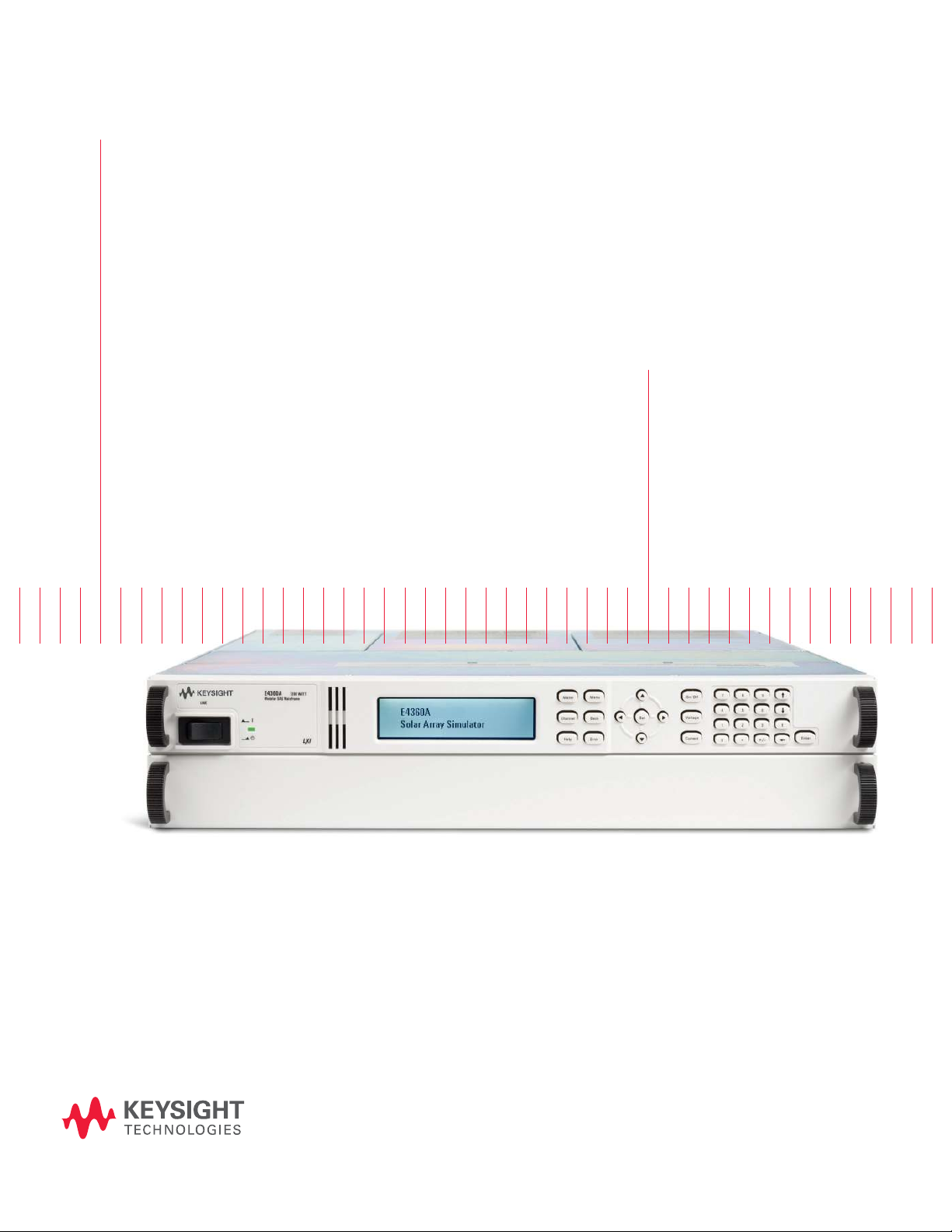
Keysight E4360
Modular Solar Array Simulators
Models: E4360-62A, E4366-68A
Data Sheet
Page 2

02 | Keysight | E4360 Modular Solar Array Simulators - Data Sheet
– Accurate simulation of any type of
solar array
– Small size: up to 2 outputs in 2U of
rack space
– High output power – up to 600 W
per output
– Fast I-V curve change and fast
recovery switching time
– Easy to simulate environmental
conditions
– LAN, USB, and GPIB interfaces
standard
– Fully compliant to LXI Class C
– Custom turn-key system or
individual instruments available
Solar Array Simulation
Satellite test applications
Solar panels consisting of
multiple solar cells provide
power to satellites. They have
unique I-V characteristics.
Since the output power varies
with environmental conditions
(temperature, irradiation)
and operational conditions
(eclipse, spin), a specialized
power supply such as the solar
array simulator (SAS) must be
used for making accurate tests
and veryifying the satellite
power system.
Residential photovoltaic (PV)
test applications
Solar panels are also used in
residential power systems to
provide power to homes. Each
solar panel output can be connected to a microinverter that
converts the DC solar panel
output into AC for use in the
home. To test microinverters,
a solar array simulator is used
to verify that the microinverter
will track the maximum power
point under various environmental conditions (such as sunny
conditions, cloudy conditions,
shadowing, and different temperatures) and to ensure that
the microinverter is reliable
and efficient.
As the trend moves toward
higher power solar panels and
more efficient inverters, there
is a need for a specialized DC
power source that is reliable, repeatable, scalable, cost effective,
and available off the shelf.
Satellite manufacturers need to
verify the design of the power
bus regulator on the ground.
Microinverter and DC power
optimizer designers need to
verify accuracy and efficiency
of the device to gain competitive
advantage in the marketplace.
Keysight Technologies, Inc.
Solar Array Simulator
The Keysight E4360 Modular
Solar Array Simulator (SAS)
is a dual output programmable
dc power source that simulates
the output characteristics of a
solar array. The E4360 SAS is
primarily a current source with
very low output capacitance and
is capable of quickly simulating
the I-V curve of different arrays
under different conditions (ex.
temperature, age etc.). It provides up to 2 outputs and up
to 1200 W in a small 2U-high
mainframe.
Whether you build your own test
system requiring instrument only
or if you want a full turn-key
system with all the instruments
and software integrated and installed – Keysight gives you the
flexibility you need. The E4360
SAS is readily available as an
off-the-shelf instrument and
also is available from Keysight
integrated into a full turn-key
solar array simulator system
configured to your exact
specification.
Page 3
03 | Keysight | E4360 Modular Solar Array Simulators - Data Sheet
Multiple simulation modes
The E4360 SAS provides three
operating modes, Simulator
(SAS), Table and Fixed modes.
To accurately simulate the I-V
cure of a solar array, use SAS
or table modes. When a standard
power supply is needed, use
fixed mode.
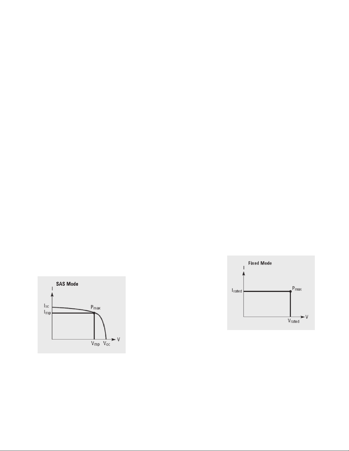
1. SAS mode:
The E4360 SAS internally
generates a 4,096 I-V point
table. An internal algorithm
is used to approximate an
I-V curve. This can be done
via the I/O interfaces or from
the front panel where a PC
is not needed. These four
input parameters are needed
to establish a curve in this
mode:
– Voc - open circuit voltage
– Isc - short circuit current
– Imp - current at the peak
power point on the curve
– Vmp - voltage at the peak
power point on the curve
2. Table mode:
The I-V curve is determined
by a user-defined table of
points. A table can have a
minimum of 3 points, up to
a maximum of 4000 points.
A point corresponds to a
specific value of I and V.
As many as 30 tables may
be stored in each of the
E4360 SAS built-in volatile
and non-volatile memory.
The tables (I-V curve) stored
in this non-volatile memory
will be retained when the
power is turned off, while
those stored in volatile memory
will be erased after power is
removed.
Additionally, current and
voltage offsets can be applied
to the selected table to simu late a change in the operating
conditions of the solar array.
3. Fixed mode:
This is the default mode
when the unit is powered on.
The unit has the rectangular
I-V characteristics of a
standard power supply.
Fast I-V curve changes
The E4360 offers fast curve
changes to enable better simulation of solar arrays under
various environmental conditions, like eclipse and spin. The
resolution of the I-V curve can
be set to optimize the I-V curve
for resolution or fast curve
change. In simulation (SAS)
mode and table mode, you can
select high resolution which
uses a 4,096 point table to
generate a smoother I-V curve
within 350 msec. For fast I-V
curve generation, you can select
the 256 point table that quickly
generates an I-V curve within
30 msec. All the E4360 SAS in
the system can be synchronized
to change their I-V curves at the
same time using the hardware
trigger, such that I-V curves can
be changed on up to 100 outputs
within 30 msec or 350 msec
based on resolution setting.
Isc
Figure 1: Power supply output
characteristic in SAS mode
Figure 2: Power supply output
characteristic in Fixed mode
Page 4
04 | Keysight | E4360 Modular Solar Array Simulators - Data Sheet
I-V curve list
The E4360 offers a LIST mode
that lets you pre-program a LIST
of up to 512 I-V curves. Program
up to 512 sets of points, where
each set of points include curve
parameters: V
Imp. A dwell time of 30 ms to
33,554 seconds with 1 ms resolution can be specified and the
E4360 SAS will stay (i.e. dwell) at
the set point for the programmed
dwell time value. Alternately,
the LIST can be paced (advanced
to the next set point) by a bus
trigger or it can be paced by a
trigger signal which enables
synchronization of the LIST
with an external event. Utilizing I-V curve lists speed up
test execution by removing the
computer I/O from the process
and simplifies I-V curve change
more easily simulating the solar
array under various conditions.
oc
V
I
,
mp
and
,
,
sc
Protection features
To safeguard your device from
damage, the E4360 module has
over-voltage, over-current, and
over-temperature protection.
The E4360 can be configured
such that a fault condition in
one module can be detected
within 10 microseconds by
other modules so that they
can be quickly shut down to
avoid hazardous conditions
on your DUT.
Connectivity
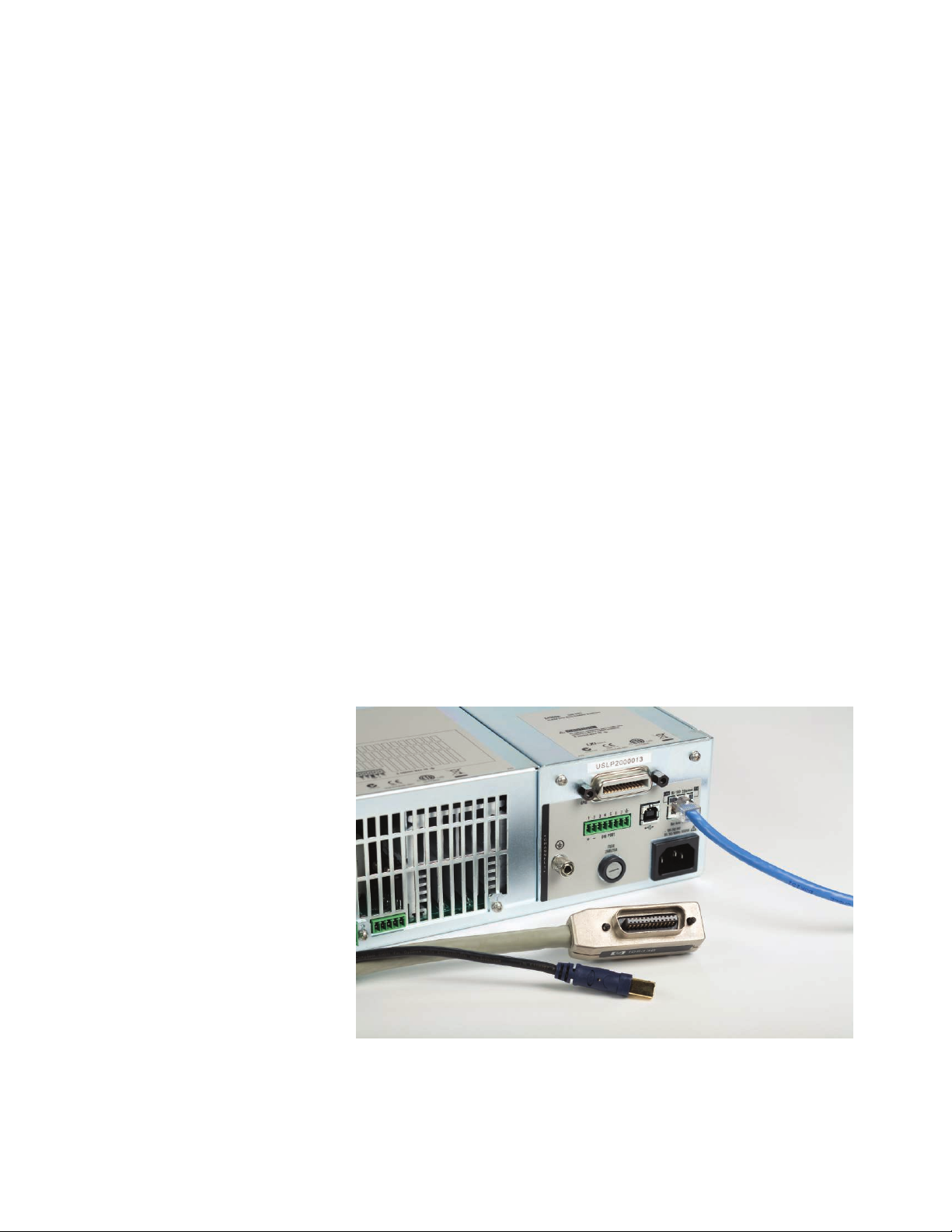
The E4360 Modular Solar Array
Simulator comes standard with
GPIB, 10/100 Base-T Ethernet LAN interfaces, and USB
2.0 interfaces, giving you the
flexibility to use your interface of choice today and in
the future. The E4360 is fully
compliant with the LXI Class C
specification.
Security
When used in systems running
GPIB, the LAN and/or USB
interfaces can be password
protected and disabled for
extra security.
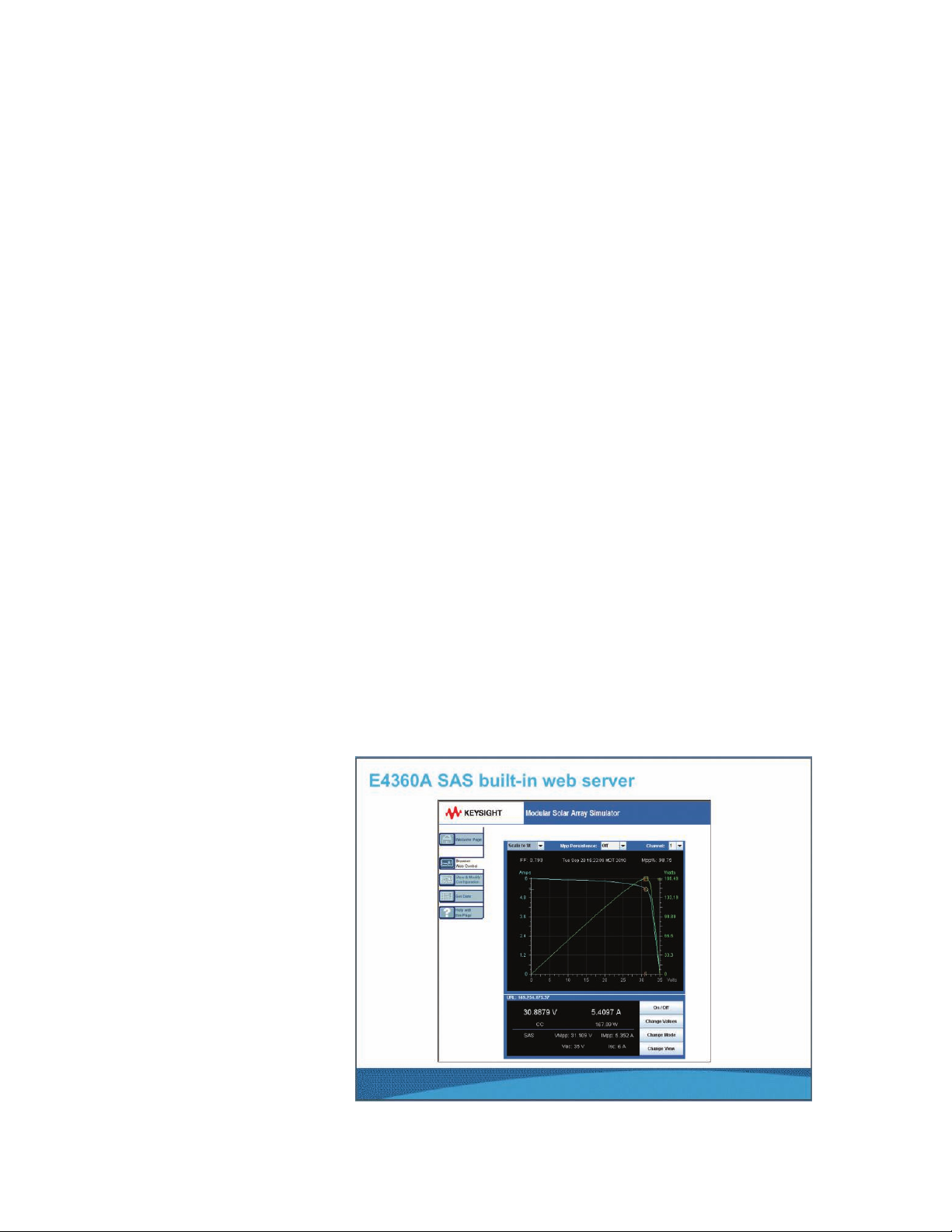
Control from any browser
The built-in web server provides
remote access and control of
the E4360 via a standard web
browser. From the web browser,
you can setup, monitor and
operate the E4360 remotely.
Easy parallel operation
Should you need greater output
power and current, the E4360
gives you the flexibility to connect similarly rated outputs in
parallel. To simplify parallel
operation, the E4360 offers a
firmware based feature that
allows it to treat 2 channels as
Small size
The Keysight E4360 provides up
to 1200 W in a small 2U high,
19 inch wide package. It has
side air vents, however 1U
space is required between the
instruments to retain proper
cooling.
Built-in measurement of
voltage and current
The E4360 modules come
standard with built-in measurement of voltage and current.
Measurements can be quickly
made on up to 100 outputs in
less than 500 msec using the
hardware trigger. Additionally,
the E4360 can simultaneously
data log both voltage and current at 10 readings/s.
Figure 3: Built-in ethernet, USB 2.0, and GPIB interfaces enables easy system connections
Page 5
05 | Keysight | E4360 Modular Solar Array Simulators - Data Sheet
a single, synchronized channel.
Once configured, all functions
(sourcing, programming, measurements, triggering, protection, and status monitoring)
behave as if there is a single
channel with twice the output
current and power capability.
Plug high power mainframes
into standard AC sockets for
quick bench checkout
When you first turn on the
E4360A Modular SAS mainframe,
the mainframe automatically
senses the voltage available
from the AC line. If the AC line
voltage is <180 Vac, the mainframe automatically scales back
the available output power to
prevent overloading the AC line
cord. The E4360A will limit the
mainframe output power to
600 W allowing the high power
mainframe to be plugged into
any standard outlet. If there is
only one module installed then
full power will be available from
that module. When two modules
are installed, the output power
of each module would be cut in
half (300 W per module). This
is very convenient for initial
bench checkout of the SAS. It
is also very convenient for test
development, which is typically
done on the bench when DUT
is not yet driven to full power.
Drivers
The E4360 comes with both the
IVI-COM driver and the System
Control Tools.
Keysight 14360A System
Control Tools
The 14360A System Control Tools
is a powerful software driver that
greatly simplifies the programming and control of a system
with multiple E4360A SAS power
supplies. It is shipped standard
with every E4360 Modular Mainframe – free of cost. There are
three components of the 14360A
System Control Tools: the system
driver, the configuration wizard,
and the server control.
The system driver
The 14360 system driver interfaces with the user’s test
application and provides the
capability for a single function
call to control up to 100 E4360
SAS outputs (50 mainframes).
The driver functions provide
support for many tasks like
configuration measurement,
and status readback of a system. It enables you to set and
measure voltage and current
levels, operating modes (Fixed,
SAS, Table), protection levels,
V
SAS mode settings (I
I
Vmp) and much more.
,
mp
The driver supports VISA and
TCP/IP sockets connection.
sc
,
,
oc
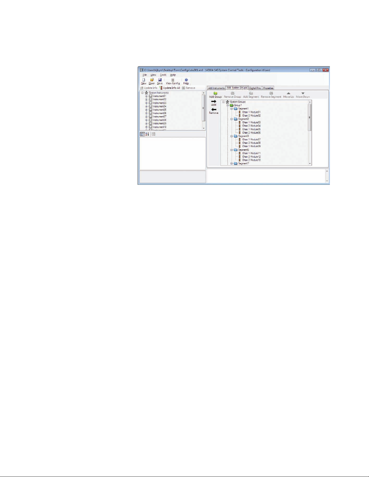
The configuration wizard is a
graphical user interface (GUI)
that lets you easily search for
and configure the layout of the
E4360 SAS system without writing a single line of code. Simply
specify the instrument search
parameters, create module
groups and segments, and drag
and drop modules to desired
segments. This wizard generates a configuration file used to
initialize the system driver.
Triggering
The E4360 Modular Solar Array
Simulator mainframe has hardware trigger in/trigger out signals
which permit the E4360 to be
synchronized with external
events. For example, all SAS in
a system can be synchronized to
change their I-V curve, to take
a voltage and current measurement, or to start a data logging.
Figure 4: Keysight E4360A built-in web server
Page 6
06 | Keysight | E4360 Modular Solar Array Simulators - Data Sheet
Server control
The server control allows access
to the system by multiple applications and an internet browser
web monitor for viewing the
status of the system.
The server control utilizes a
client-server model, enabling
a remote PC to communicate
with the SAS system PC. Through
the use of dual Ethernet cards
in the PC running the server
control, clients can access the
SAS system remotely. Placing
the SAS system on its own private network simplifies system
maintenance and new system
development allowing system
configurations to be duplicated.
The web monitor allows you
to remotely monitor your
system of E4360s. From any
web browser, you can view the
overall system driver status,
the system layout along with
module measurement and status, and more. It also provides
a linkage to the webGUI that
is available for an individual
E4360 instrument allowing you
to configure and control that
instrument. The webGUI can
be password protected. This is
a great tool for monitoring and
troubleshooting a system of
E4360s.
Figure 5: Keysight 14360A system control tools: configuration wizard
Programming language
The E4360 supports easy-to-use
SCPI (Standard Commands for
Programmable Instruments).
Firmware updates
The E4360 firmware is stored in
FLASH ROM and can be easily
updated when new features become available. Firmware can
be downloaded into the E4360
over GPIB, LAN, or USB using
the supplied firmware update
utility program. Firmware
updates can be found at
www.keysight.com/find/E4360firmware.
Front panel
In addition to full control over
its three standard interfaces,
the E4360 has a full featured
front panel to permit easy manual
operation for test prototyping,
debugging, and troubleshooting
when used in an ATE system.
You can have confidence that
the E4360 is working properly
because you can view the settings and actual output values
on both outputs at the same
time. Further, all SAS modes
can be programmed and controlled from the front panel.
Analog programming and
monitoring
In fixed mode, the output current
can be programmed from zero
to full scale by an analog voltage
of 0 to –4 V.
Page 7
07 | Keysight | E4360 Modular Solar Array Simulators - Data Sheet
Universal AC input
The E4360 has a universal
input that operates from 100240Vac, 50/60/400 Hz. There
are no switches to set or fuses
to change when switching from
one voltage standard to another.
The ac input employs power
factor correction. In order to
get full output power when a
mainframe is configured with two
modules, it must be connected
to an ac input of ≥ 180 Vac; else
output power will be limited to
600 W.
Quick disconnects
Each power module has quick
disconnects for easy system
setup and maintenance.
Rack mount kit
The E3460 is easily rack-mounted
using available option 908. This
kit provides all the necessary
hardware to rack mount one
E4360A mainframe in 2U of
rack space. This rack mount kit
includes front rack ears and
rear supports which take the
place of standard rack rails
and/or slides.
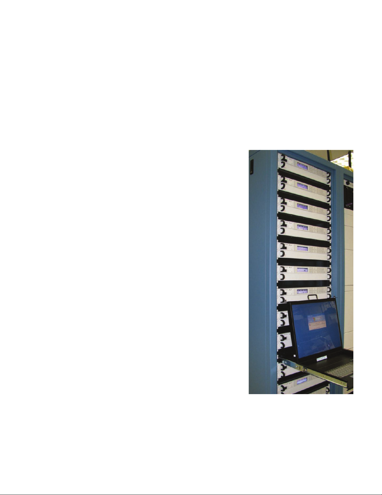
Custom turn-key system
Keysight offers an affordable full
turn-key solar array simulator
system with all the instruments,
and software integrated and
installed. Save valuable system
development time by letting
Keysight handle all the system
design elements. This SAS
system is built on the E4360
Modular Solar Array Simulator
platform making this system
the smallest available on the
market. The E4360 modular
architecture makes it easy to
configure, re-configure, and
support this system since modules can be easily moved and
replaced. Further the system’s
components are made up of
commercial-off-the-shelf instruments, a standard PC and
standard interconnectivity (LAN,
USB) for lower cost, easier support, and reduced down time.
Keysight will tailor the system
to your exact specification.
Contact your local Keysight
sales office to learn more
about our custom systems.
Whether you need spares, want
to configure the system yourself
or want Keysight to build your
system – the E4360 gives you
the flexibility to choose the
configuration that best meets
your test strategy.
While the E4360 Modular Solar
Array Simulator will meet most
of your needs, Keysight recognizes that these SAS may not
match all needs. To better solve
your specific problem, Keysight
offers a special modification
service. This service entails the
design and manufacture of a
modified version of standard
E4360 SAS models. Typical
modifications include changes
to the maximum output voltage
or current within the power
ratings. The modified SAS are
designed, manufactured, tested,
to Keysight’s high quality and
reliability standards.
While the scope of this service
is usually limited to the modification of a standard SAS, our
engineers welcome a discussion
to determine the feasibility of
meeting your specific requirements. Contact your local
Keysight sales office with your
modification request.
Figure 6: Custom turnkey system
Page 8

08 | Keysight | E4360 Modular Solar Array Simulators - Data Sheet
Unless otherwise noted, specifications are warranted over the ambient temperature range of 0°C to 40°C and are applicable for
Fixed, Simulator, and Table modes
E4361A E4362A E4362A-J01 E4362A-J02
Output Ratings Maximum Power 510 W 600 W 594 W 594 W
(Simulator and
Table mode)
Line Voltage: Maximum Short Circuit Current (I
Maximum Open Circuit Voltage (Voc) 65 V 130 V 117 V 120 V
Maximum Voltage Point (Vmp) 60 V 120 V 108 V 110 V
) 8.5 A 5.0 A 5.5 A 5.4 A
200 V/230 V/240 V
Line Voltage:
100 V/120 V
4
Maximum Current Point (Imp)1 4.25 A 2.5 A 2.75 A 2.7 A
Maximum Circuit Point (Imp)1 8.5 A 5.0 A 5.5 A 5.4 A
Maximum Short Circuit Current (Isc) 4.25 A 2.5 A 2.75 A 2.7 A
sc
Output Ratings Minimum Impedance
(ΔV/ΔVl)
(Fixed mode)
Voltage 0 - 60 V 0 - 120 V 0 - 108 V 0 - 110 V
1
0.25 Ω 1 Ω 1 Ω 1 Ω
Line Voltage: Current 0 - 8.5 A 0 - 5.0 A 0 - 5.5 A 0 - 5.4 A
200 V/230 V/240 V
100 V/120 V
Line Voltage:
4
Current 0 - 4.25 A 0 - 2.5 A 0 - 2.75 A 0 - 2.7 A
Current Derating Factor 0.11 A/°C 0.069 A/°C 0.069 A/°C 0.068 A/°C
(from 40 to 55 °C)
Output Voltage Ripple & Noise Simulator/Table mode 20 mV
(from 20 Hz to 20 MHz with a 125 mV
resistive load, outputs ungrounded,
or either output grounded)
Programming Accuracy
2,3
Fixed mode (constant voltage) 24 mV
150 mV
Fixed Mode Voltage 0.075% + 25 mV 0.075% + 50 mV 0.075% + 50 mV 0.075% + 50 mV
24 mV
rms
195 mVp
p-p
30 mV
rms
150 mV
p-p
rms
rms
p-p
24 mV
rms
195 mV
30 mV
150 mV
p-p
rms
p-p
-p
24 mV
195 mV
30 mV
150 mV
rms
rms
p-p
p-p
(@ 23 ±5 °C) Fixed Mode Current 0.2% + 20 mA 0.2% + 10 mA 0.2% + 11 mA 0.2% + 11 mA
Readback Accuracy
3
(from front panel or over GPIB with
respect to actual output @ 23 ±5 °C)
Voltage 0.08% + 25 mV 0.08% + 50 mV 0.08% + 50 mV 0.08% + 50 mV
+Current 0.20% + 20 mA 0.20% + 10 mA 0.20% + 11 mA 0.20% + 11 mA
−Current 0.35% + 48 mA 0.35% + 24 mA 0.35% + 26 mA 0.35% + 26 mA
Load Regulation – Fixed Mode Constant voltage 2 mV 2 mV 2 mV 2 mV
(change in output voltage or current for
any load change within ratings)
Constant current 1 mA 1 mA 1 mA 1 mA
Line Regulation – Fixed Mode Constant voltage 2 mV 2 mV 2 mV 2 mV
(change in output voltage or current for
any line voltage change within ratings)
1
There is no maximum impedance restriction. The programmed value for I
2
In Simulator mode, the output current is related to the readback output voltage by an internal algorithm. In Table mode, the output current is related
to the readback output voltage by interpolation between points that are entered by the user.
3
The unit may go out of specification when subjected to RF fields of 3 volts/meter in the frequency range of 26 MHz to 1 GHz.
4
There is no current derating when only one output module is installed in the mainframe.
Constant current 1 mA 1 mA 1 mA 1 mA
can be less than or equal to Isc.
mp
Page 9

09 | Keysight | E4360 Modular Solar Array Simulators - Data Sheet
(Continued)
Unless otherwise noted, specifications are warranted over the ambient temperature range of 0 to 40 °C and are applicable for Fixed,
Simulator, and Table modes
E4361A-J01 E4362A-J03 E4362A-J04 E4362A-J05
Output Ratings Maximum Power 498 W 598 W 596 W 552.5 W
(Simulator and
Table mode)
Line Voltage: Maximum Short Circuit Current (I
Line Voltage:
Maximum Open Circuit Voltage (Voc) 58 V 108 V 170 V 95 V
Maximum Voltage Point (Vmp) 53.5 V 99.7 V 157 V 87.7 V
200 V/230 V/240 V
100 V/120 V
Minimum Impedance
(ΔV/ΔVl)
Maximum Current Point (Imp)1 9.3 A 6 A 3.8 A 6.3 A
Maximum Short Circuit Current (Isc) 4.65 A 3 A 1.9 A 3.15 A
4
Maximum Current Point (Imp) 4.65 A 3 A 1.9 A 3.15 A
1
1 Ω 1 Ω 1.72 Ω 1 Ω
) 9.3 A 6 A 3.8 A 6.3 A
sc
Output Ratings Voltage 0 - 53.5 V 0 - 99.7 V 0 - 157 V 0 - 87.7 V
(Fixed mode)
Line Voltage: Current 0 - 9.3 A 0 - 6 A 0 - 3.8 A 0 - 6.3 A
200 V/230 V/240 V
100 V/120 V
Line Voltage:
4
Current 0 - 4.65 A 0 - 3 A 0 - 1.9 A 0 - 3.15 A
Current Derating Factor 0.12 A/°C 0.075 A/°C 0.048 A/°C 0.079 A/°C
(from 40 to 55 °C)
Output Voltage Ripple & Noise Simulator/Table mode 20 mV
(from 20 Hz to 20 MHz with a 125 mV
resistive load, outputs ungrounded,
or either output grounded)
Programming Accuracy
(@ 23 ±5 °C)
Fixed Mode Current 0.2% + 22 mA 0.2% + 12 mA 0.2% + 8 mA 0.2% + 15 mA
Readback Accuracy
2,3
3
(from front panel or over GPIB with
respect to actual output @ 23 ±5 °C)
Fixed mode (constant voltage) 24 mV
150 mV
Fixed Mode Voltage 0.075% + 22 mV 0.075% + 42 mV 0.075% + 65 mV 0.075% + 37 mV
Voltage 0.08% + 22 mV 0.08% + 42 mV 0.08% + 65 mV 0.08% + 37 mV
+Current 0.20% + 23 mA 0.20% + 12 mA 0.20% + 8 mA 0.20% + 15 mA
−Current 0.35% + 53 mA 0.35% + 29 mA 0.35% + 19 mA 0.35% + 36 mA
23 mV
rms
175 mVp
p-p
28 mV
rms
150 mV
p-p
rms
rms
p-p
32 mV
rms
250 mV
40 mV
195 mV
p-p
rms
p-p
-p
22 mV
158 mV
27 mV
150 mV
rms
p-p
rms
p-p
Load Regulation – Fixed Mode Constant voltage 2 mV 3 mV 3 mV 2 mV
(change in output voltage or current for
any load change within ratings)
Constant current 1 mA 1 mA 1 mA 1 mA
Line Regulation – Fixed Mode Constant voltage 2 mV 2 mV 2 mV 2 mV
(change in output voltage or current for
any line voltage change within ratings)
Constant current 1 mA 1 mA 1 mA 1 mV
1
There is no maximum impedance restriction. The programmed value for I
2
In Simulator mode, the output current is related to the readback output voltage by an internal algorithm. In Table mode, the output current is related
to the readback output voltage by interpolation between points that are entered by the user.
3
The unit may go out of specification when subjected to RF fields of 3 volts/meter in the frequency range of 26 MHz to 1 GHz.
4
There is no current derating when only one output module is installed in the mainframe.
can be less than or equal to Isc.
mp
Page 10

10 | Keysight | E4360 Modular Solar Array Simulators - Data Sheet
Supplemental Characteristics for Keysight E4361A and E4362A SAS Modules
Supplemental characteristics are not warranted but are descriptions of typical performance determined either by design or type
testing.
E4361A E4362A E4362A-J01 E4362A-J02
Output Current Ripple & Noise Simulator/Table mode 4 mA
(from 20 Hz to 20 MHz with a 32 mA
resistive load, outputs ungrounded,
or either output grounded)
Output Programming
Range
Fixed mode Voltage 0 - 61.5 V 0 - 123 V 0 - 110.7 V 0 - 112.8 V
(maximum
programmable
values)
Simulator/Table mode Voltage 0 - 65 V 0 - 130 V 0 - 117 V 0 - 120 V
Line Voltage: Current 0 - 8.66 A 0 - 5.1 A 0 - 5.61 A 0 - 5.51 A
200 V/230 V/240 V
Line Voltage:
100 V/120 V
Fixed mode (constant current) 2.5 mA
19 mA
Current 0 - 4.33 A 0 - 2.55 A 0 - 2.81 A 0 - 2.75 A
1
Overvoltage Protection 0 - 74 V 0 -140 V 0 -127 V 0 -129 V
4 mA
rms
32 mA
p-p
2.5 mA
rms
19 mA
p-p
rms
p-p
p-p
rms
4 mA
32 mA
3 mA
20 mA
rms
p-p
rms
p-p
4 mA
32 mA
3 mA
20 mA
rms
p-p
rms
p-p
Overcurrent Limit 0 - 10.6 A 0 - 6.25 A 0 - 6.88 A 0 - 6.75 A
Programming Resolution Voltage 19 mV 37 mV 35 mV 35 mV
(average values)
Current 2.7 mA 1.6 mA 1.8 mA 1.7 mA
Overvoltage Protection 325 mV 600 mV 575 mV 575 mV
Over
current Limit 46 mA 27 mA 31 mA 30 mA
Programming Accuracy Overvoltage Protection 0.65 V 1.2 V 1.1 V 1.1 V
Overcurrent Limit 0.5% + 215 mA 0.5% + 125 mA 0.5% + 140 mA 0.5% + 135 mA
Current Monitor (referenced to P common)
1.0% + 130 mA 1.0% + 75 mA 1.0% + 85 mA 1.0% + 81 mA
Fixed Mode Analog Analog Programming 1.0% + 5.5 mA 1.0% + 3.2 mA 1.0% + 3.5 mA 1.0% + 3.4 mA
Current Programming +Ip to −Ip Differential Input 0 to -4 V 0 to -4 V 0 to -4 V 0 to -4 V
(0 to full scale)
(referenced to +OUT)
Nominal Input Impedance 20 kΩ 20 kΩ 20 kΩ 20 kΩ
Drift/Temperature Stability
(change in output over 8 hours under
constant load, line, and ambient,
Max. common mode voltage
±18 V ±18 V ±18 V ±18 V
Voltage 0.04% + 1 mV 0.04% + 2 mV 0.04% + 2 mV 0.04% + 2 mV
Current 0.1% + 0.85 mA 0.1% + 0.5 mA 0.1% + 0.55 mA 0.1% + 0.54 mA
following a 30 minute warmup)
Temperature Coefficients Voltage 0.01% + 325 µV 0.01% + 650 µV 0.01% + 650 µV 0.01% + 650 µV
(output change per °C)
Current
0.025% + 215 µA
0.025% + 125 µA 0.025% + 140 µA 0.025% + 135 µA
Output Capacitance < 100 nF < 50 nF < 50 nF < 50 nF
Maximum Reverse Diode Current 8.5 A 5.0 A 5.5 A 5.4 A
(with fans running)
1
There is no current derating when only one output module is installed in the mainframe.
Page 11

11 | Keysight | E4360 Modular Solar Array Simulators - Data Sheet
Supplemental Characteristics for Keysight E4361A and E4362A SAS Modules
(Continued)
Supplemental characteristics are not warranted but are descriptions of typical performance determined either by design or type
testing.
E4361A-J01 E4362A-J03 E4362A-J04 E4362A-J05
Output Current Ripple & Noise Simulator/Table mode 4 mA
(from 20 Hz to 20 MHz with a 32 mA
resistive load, outputs ungrounded,
or either output grounded)
Output Programming
Range
Fixed mode Voltage 0 - 54.8 V 0 - 102.2 V 0 - 161 V 0 - 89.9 V
(maximum
programmable
values)
Overcurrent Limit 0 - 11.6 A 0 - 7.5 A 0 - 4.75 A 0 - 7.9 A
Programming Resolution Voltage 17 mV 31 mV 48 mV 27 mV
(average values)
Overvoltage Protection 295 mV 510 mV 785 mV 452 mV
Over
Programming Accuracy Overvoltage Protection 0.6 V 1.0 V 1.56 V 0.9 V
Overcurrent Limit 0.5% + 235 mA 0.5% + 150 mA 0.5% + 100 mA 0.5% + 159 mA
Fixed Mode Analog Analog Programming 1.0% + 6 mA 1.0% + 3.9 mA 1.0% + 2.5 mA 1.0% + 4.1 mA
Current Programming +Ip to −Ip Differential Input 0 to -4 V 0 to -4 V 0 to -4 V 0 to -4 V
(0 to full scale)
(referenced to +OUT)
Nominal Input Impedance 20 kΩ 20 kΩ 20 kΩ 20 kΩ
Drift/Temperature Stability
(change in output over 8 hours under
constant load, line, and ambient,
following a 30 minute warmup)
Temperature Coefficients Voltage 0.01% + 290 µV 0.01% + 540 µV 0.01% + 850 µV 0.01% + 475 µV
(output change per °C)
Simulator/Table mode Voltage 0 - 58 V 0 - 108 V 0 - 170 V 0 - 95 V
Line Voltage: Current 0 - 9.5 A 0 - 6.12 A 0 - 3.875 A 0 - 6.42 A
200 V/230 V/240 V
Line Voltage:
100 V/120 V
Current 3.0 mA 1.9 mA 1.2 mA 2 mA
Current
Fixed mode (constant current) 2.5 mA
19 mA
Current 0 - 4.75 A 0 - 3.06 A 0 - 1.938 A 0 - 3.21 A
1
Overvoltage Protection 0 - 66.7 V 0 - 117.3 V 0 - 181.3 V 0 -103.9 V
current Limit 52 mA 32 mA 22 mA 34 mA
Current Monitor (referenced to P common)
Max. common mode voltage
Voltage 0.04% + 0.9 mV 0.04% + 1.7 mV 0.04% + 2.6 mV 0.04% + 1.5 mV
Current 0.1% + 0.93 mA 0.1% + 0.6 mA 0.1% + 0.4 mA 0.1% + 630 A
1.0% + 140 mA 1.0% + 90 mA 1.0% + 60 mA 1.0% + 96 mA
4 mA
rms
32 mA
p-p
2.5 mA
rms
19 mA
p-p
±18 V ±18 V ±18 V ±18 V
0.025% + 235 µA
rms
p-p
rms
p-p
0.025% + 150 µA 0.025% + 100 µA 0.025% + 159 µA
4 mA
32 mA
2.5 mA
19 mA
rms
p-p
p-p
rms
4 mA
32 mA
2.5 mA
19 mA
rms
p-p
rms
p-p
Output Capacitance < 100 nF < 50 nF < 50 nF < 100 nF
Maximum Reverse Diode Current 9.3 A 6 A 3.8 A 6.3 A
(with fans running)
1
There is no current derating when only one output module is installed in the mainframe.
Page 12

12 | Keysight | E4360 Modular Solar Array Simulators - Data Sheet
Supplemental Characteristics for Keysight E4361A and E4362A SAS Modules
(Continued)
Supplemental characteristics are not warranted but are descriptions of typical performance determined either by design or type
testing.
E4361A E4362A E4362A-J01 E4362A-J02
Output Current Settling Time
(output recovery to within 1.5 A of an
operating point on the I-V curve (V < 90%
of VMP) after switching from a short
circuit to a fixed load)
Maximum Capacitive Load Simulator/Table mode 2000 µF 2000 µF 2000 µF 2000 µF
(for stable operation)
Load Lead Drop with Remote Sensing Simulator/Table mode Up to 2 volts + Up to 2 volts + Up to 2 volts + Up to 2 volts +
(V
Fixed mode Up to 2 volts Up to 2 volts Up to 2 volts Up to 2 volts
total total total total
Current Sinking Capability Simulator/Table mode 500 mA 500 mA 500 mA 500 mA
Fixed mode 440 mA 440 mA 440 mA 440 mA
Voltage Programming Rise/Fall Time < 8 ms < 8 ms < 8 ms < 8 ms
(time for output to change from 90% to 10%
or 10% to 90% of its total excursion)
Voltage Programming Settling Time 25 ms 25 ms 25 ms 25 ms
(time for output change to settle within 0.1% of typical typical typical typical
the rating of the unit; either 60 mV or 120 mV)
Monotonicity
Auto-Parallel Configuration
Series and Shunt Switching Frequency
(switching frequency is controlling
by a customer-supplied external series
or shunt FET connected to the output)
Fixed mode
maximum
Output is monotonic over entire rated voltage, current, temperature range
< 5 µs < 5 µs < 5 µs < 5 µs
2000 µF
2000 µF 2000 µF 2000 µF
- Vmp) (Voc - Vmp) (Voc - Vmp) (Voc - Vmp)
oc
Up to 4 Up to 4 Up to 4 Up to 4
outputs outputs outputs outputs
50 kHz 50 kHz 50 kHz 50 kHz
1
maximum
1
maximum
1
maximum
1
Output Terminal Isolation
(maximum, from chassis ground)
Recommended Calibration Interval
1
Higher switching frequencies may be possible given the right load conditions consisting of but not necessarily limited to the inductance of the load
cable to the shunt switch and the on/off edge rate of the shunt switch.
±240 Vdc ±240 Vdc ±240 Vdc ±240 Vdc
1 year 1 year 1 year 1 year
Page 13

13 | Keysight | E4360 Modular Solar Array Simulators - Data Sheet
Supplemental Characteristics for Keysight E4361A and E4362A SAS Modules
Supplemental characteristics are not warranted but are descriptions of typical performance determined either by design or type
testing.
E4361A-J01 E4362A-J03 E4362A-J04 E4362A-J05
Output Current Settling Time
(output recovery to within 1.5 A of an
operating point on the I-V curve (V < 90%
of VMP) after switching from a short
circuit to a fixed load)
Maximum Capacitive Load Simulator/Table mode
(for stable operation)
Load Lead Drop with Remote Sensing Simulator/Table mode Up to 2 volts + Up to 2 volts + Up to 2 volts + Up to 2 volts +
(V
Fixed mode Up to 2 volts Up to 2 volts Up to 2 volts Up to 2 volts
total total total total
Current Sinking Capability Simulator/Table mode 560 mA 560 mA 400 mA 560 mA
Fixed mode 440 mA 440 mA 340 mA 440 mA
Voltage Programming Rise/Fall Time < 8 ms < 8 ms < 8 ms < 8 ms
(time for output to change from 90% to 10%
or 10% to 90% of its total excursion)
Voltage Programming Settling Time 25 ms 25 ms 25 ms 25 ms
(time for output change to settle within 0.1% of typical typical typical typical
the rating of the unit; either 60 mV or 120 mV)
Monotonicity
Auto-Parallel Configuration
Series and Shunt Switching Frequency
(switching frequency is controlling
by a customer-supplied external series
or shunt FET connected to the output)
Fixed mode
maximum
Output is monotonic over entire rated voltage, current, temperature range
< 5 µs < 5 µs < 5 µs < 5 µs
2000 µF
2000 µF
2000 µF 2000 µF 2000 µF
- Vmp) (Voc - Vmp) (Voc - Vmp) (Voc - Vmp)
oc
Up to 4 Up to 4 Up to 4 Up to 4
outputs outputs outputs outputs
50 kHz 50 kHz 45 kHz 50 kHz
2000 µF
1
maximum
2000 µF
1
maximum
2000 µF
1
maximum
1
Output Terminal Isolation
(maximum, from chassis ground)
Recommended Calibration Interval
1
Higher switching frequencies may be possible given the right load conditions consisting of but not necessarily limited to the inductance of the load
cable to the shunt switch and the on/off edge rate of the shunt switch.
±240 Vdc ±240 Vdc ±240 Vdc ±240 Vdc
1 year 1 year 1 year 1 year
Page 14

14 | Keysight | E4360 Modular Solar Array Simulators - Data Sheet
Keysight E4360A Modular SAS Mainframe
Supplemental characteristics
E4360A
Maximum Total Output Power 1200 W
(= sum of total module output power)
AC Mains Nominal input ratings 100/120/220/240 VAC; 50/60/400 Hz
Input range 86 VAC – 264 VAC
Power consumption 2000 VA (mainframe has power factor correction)
AC line spike ratings 1 kV typical
Fuse 15 A/250 VAC bib-time delay (Keysight p/n 2110-0054)
100/120 VAC Note AC mains circuits rated at nominal 100-120 VAC cannot supply enough
current to power the E4360A mainframe when two output modules are
installed. In this case, internal circuits will limit the output current of the
modules to one half of their rating. For a single installed module, full
output current will be available at nominal 100-120 VAC
Savable States Memory locations: 2 (0 and 1)
Pre-stored state: 0
Command Processing Time ≤1 ms from receipt of command to start of output change
Protection Response Characteristics INH input 5 s from receipt of inhibit to start of shutdown
Fault on coupled outputs
Interface Capabilities GPIB SCPI - 1993, IEEE 488.2 compliant interface
USB 2.0 Requires Keysight IO Library version M.01.01 and up, or 14.0 and up
Built-in Web server Requires Internet Explorer 5+ or Netscape 6.2+
Environmental Conditions Operating environment Indoor use, installation category II (for AC input), pollution degree 2
Relative humidity Up to 95%
Storage temperature –30 to 70 °C
LED statement Any LEDs used in this product are Class 1 LEDs
as per IEC 825-1
LXI Compliance
10/100 LAN Requires Keysight IO Library version L.01.01 and up, or 14.0 and up
Temperature range
Altitude Up to 2000 meters
<10 s from receipt of fault to start of shutdown
Class C
0 to 55 °C (current is derated 1% per °C above 40°C ambient temperature)
Page 15

15 | Keysight | E4360 Modular Solar Array Simulators - Data Sheet
Keysight E4360A Modular SAS Mainframe (Continued)
Supplemental characteristics (continued)
E4360A
Regulatory Compliance EMC Complies with the European EMC directive for Class A test and
measurement products.
This ISM device complies with Canadian ICES-001.
Electrostatic discharges greater than 1 kV near the I/O connectors may
cause the unit to reset and require operator intervention
Safety Complies with the European Low Voltage Directive and carries
the CE-marking.
Complies with the US and Canadian safety standards for test and
measurement products
Complies with the Australian standard and carries the C-Tick mark.
Cet appareil ISM est conforme à la norme NMB-001 du Canada.
Acoustic Noise Declaration
This statement is provided to
comply with the requirements of According to EN 27779 (Type Test). Schalldruckpegel Lp <70 dB(A)
the German Sound Emission Am Arbeitsplatz, Normaler Betrieb, Nach EN 27779 (Typprüfung).
Directive, from 18 January 1991.
Dimensions Height 88.1 mm (3.5 in.)
Depth 633.9 mm (24.96 in.)
Net Weight Mainframe with 2 modules 38.4 lbs (17.6 kg)
Width
Single output module 7.2 lbs (3.3 kg)
Sound Pressure Lp < 70 dB(A), At Operator Position, Normal Operation,
432.5 mm (17.03 in.)
Page 16
16 | Keysight | E4360 Modular Solar Array Simulators - Data Sheet
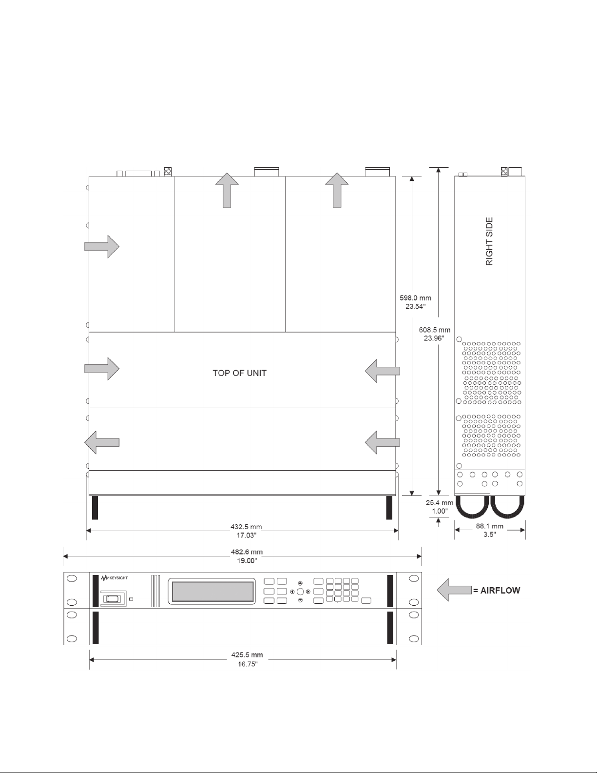
Outline diagram
Page 17

17 | Keysight | E4360 Modular Solar Array Simulators - Data Sheet
Ordering Information
The E4360A Modular Solar
Array Simulator (SAS) is
available 2 ways:
(1) You can order an E4360A mainframe and various modules as separate products. (See steps below.)
Each item will arrive in a separate
box so that you can assemble the
SAS yourself when you need to.
(2) You can order an E4366A,
E4367A, or E4368A which is a preconfigured SAS that is shipped as
a fully assembled multiple-output
SAS. (See page 18 for E4367A and
E4368A ordering information.)
When ordering the E4360 SAS as
a mainframe and modules, follow
these steps:
Ste p 1:
Select the E4360A mainframe.
Step 2:
Select the appropriate documentation and line cord options.
Step 3:
Order up to 2 modules.
each mainframe has 2 module
slots to hold modules. Each module
occupies one module slot.
Step 4:
For proper operation, you must fill
any empty module slots with a filler
panel. When configuring a mainframe
with less than 2 filled module slots,
you MUST order a Filler Panel Kit
(Option FLR or E4369A). Each kit
contains 1 filler panel to fill one
empty module slot.
Step 5:
If you will be rack mounting your
E4360 SAS, you MUST order the
Rack Mount Kit.
Note that
Mainframe
E4360A Modular Solar Array Simulator Mainframe, 1200 W
Holds up to 2 modules
Available options to the E4360A mainframe
Opt 908 Rack Mount Kit
Required for rack mounting. Standard rack mount
hardware will not work.
Opt FLR Filler Panel Kit
Required when you have only 1 module in a mainframe.
Each filler panel kit contains one filler panel.
This filler panel kit is also orderable as product E4369A.
Opt 0L1 Full documentation on CD-ROM and printed Users Guide
Opt 0B0 Full documentation on CD-ROM only. No printed
documentation package.
Opt 0L2 Extra copy of standard printed documentation package
Opt 900 Power Cord, United Kingdom
Opt 901 Power Cord, Australia, New Zealand
Opt 902 Power Cord, Europe
Opt 903 Power Cord, USA, Canada – 120 V
Note: The maximum output power is limited to 600 W at
100/120 Vac. To achieve full output power of 1200 W, you
must use option 904 and operate at 220/240 Vac.
Opt 904 Power Cord, USA, Canada – 240 V
Opt 906 Power Cord, Switzerland
Opt 912 Power Cord, Denmark
Opt 917 Power Cord, India
Opt 918 Power Cord, Japan
Opt 919 Power Cord, Israel
Opt 920 Power Cord, Argentina
Opt 921 Power Cord, Chile
Opt 922 Power Cord, China
Opt 923 Power Cord, South Africa
Opt 927 Power Cord, Brazil, Philippine, Thailand
Opt 931 Power Cord, Taiwan
Opt 932 Power Cord, Cambodia
Modules
E4361A Solar Array Simulator dc Module 65 V, 8.5 A, 510 W
E4362A Solar Array Simulator dc Module 130 V, 5 A, 600 W
Available options to the E4360A modules
Opt 1A7 ISO 17025 Calibration Certificate
Opt A6J ANSI/NCSL Z540 Calibration Certificate
Opt UK6 Commercial calibration with test results data
Page 18

18 | Keysight | E4360 Modular Solar Array Simulators - Data Sheet
Ordering Information
E4366A, E4367A and
mainframes
These model numbers are preconfigured mainframes that are shipped
as a fully tested and assembled
instrument. Each system consists of
one mainframe and two modules. The
E4367A consists of an E4360A mainframe and two E4361A low voltage
modules. The E4368A consists of an
E4360A mainframe and two E4362A
high voltage modules. The E4366A
consists of an E4360A mainframe
and two special option modules.
If you prefer to purchase a Modular
Solar Array Simulator mainframe
and modules as separate pieces,
see page 17.
Related Literature
Keysight E4360 Modular Solar Array
Simulators Data Sheet
Keysight Solar Array Simulator
Turnkey System
E4360 Modular Solar Array Simulator
User Guide
14360A System Control Tools User's
Guide
E4367A Configured E4360A SAS Mainframe with 2 E4361A Modules
E4368A Configured E4360A SAS Mainframe with 2 E4362A Modules
Available options to the E4367A and E4368A mainframes
Opt 908 Rack Mount Kit
Required for rack mounting. Standard rack mount
hardware will not work.
Opt FLR Filler Panel Kit
Required when you have only 1 module in a mainframe.
Each filler panel kit contains one filler panel.
This filler panel kit is also orderable as product E4369A.
Opt 0L1 Full documentation on CD-ROM and printed Users Guide
Opt 0B0 Full documentation on CD-ROM only. No printed
documentation package.
Opt 0L2 Extra copy of standard printed documentation package
Opt 900 Power Cord, United Kingdom
Opt 901 Power Cord, Australia, New Zealand
Opt 902 Power Cord, Europe
Opt 903 Power Cord, USA, Canada – 120 V
Note: The maximum output power is limited to 600 W at
100/120 Vac. To achieve full output power of 1200 W, you
must use option 904 and operate at 220/240 Vac.
Opt 904 Power Cord, USA, Canada – 240 V
Opt 906 Power Cord, Switzerland
Opt 912 Power Cord, Denmark
Opt 917 Power Cord, India
Opt 918 Power Cord, Japan
Opt 919 Power Cord, Israel
Opt 920 Power Cord, Argentina
Opt 921 Power Cord, Chile
Opt 922 Power Cord, China
Opt 923 Power Cord, South Africa
Opt 927 Power Cord, Brazil, Philippine, Thailand
Opt 931 Power Cord, Taiwan
Opt 932 Power Cord, Cambodia
Available options to the E4367A and E4368A modules
Opt 1A7 ISO 17025 Calibration Certificate
Opt A6J ANSI/NCSL Z540 Calibration Certificate
Opt UK6 Commercial calibration with test results data
Page 19

19 | Keysight | E4360 Modular Solar Array Simulators - Data Sheett
myKeysight
www.keysight.com/find/mykeysight
A personalized view into the information most relevant to you.
www.axiestandard.org
AdvancedTCA® Extensions for Instrumentation and Test (AXIe) is an
open standard that extends the AdvancedTCA for general purpose and
semiconductor test. Keysight is a founding member of the AXIe consortium.
ATCA®, AdvancedTCA®, and the ATCA logo are registered US trademarks of
the PCI Industrial Computer Manufacturers Group.
www.lxistandard.org
LAN eXtensions for Instruments puts the power of Ethernet and the
Web inside your test systems. Keysight is a founding member of the LXI
consortium.
www.pxisa.org
PCI eXtensions for Instrumentation (PXI) modular instrumentation delivers a
rugged, PC-based high-performance measurement and automation system.
Three-Year Warranty
www.keysight.com/find/ThreeYearWarranty
Keysight’s commitment to superior product quality and lower total cost
of ownership. The only test and measurement company with three-year
warranty standard on all instruments, worldwide.
Keysight Assurance Plans
www.keysight.com/find/AssurancePlans
Up to five years of protection and no budgetary surprises to ensure your
instruments are operating to specification so you can rely on accurate
measurements.
www.keysight.com/quality
Keysight Technologies, Inc.
DEKRA Certified ISO 9001:2008
Quality Management System
Keysight Channel Partners
www.keysight.com/find/channelpartners
Get the best of both worlds: Keysight’s measurement expertise and product
breadth, combined with channel partner convenience.
For more information on Keysight
Technologies’ products, applications or
services, please contact your local Keysight
office. The complete list is available at:
www.keysight.com/find/contactus
Americas
Canada (877) 894 4414
Brazil 55 11 3351 7010
Mexico 001 800 254 2440
United States (800) 829 4444
Australia 1 800 629 485
China 800 810 0189
Hong Kong 800 938 693
India 1 800 112 929
Japan 0120 (421) 345
Korea 080 769 0800
Malaysia 1 800 888 848
Singapore 1 800 375 8100
Taiwan 0800 047 866
Other AP Countries (65) 6375 8100
Europe & Middle East
Austria 0800 001122
Belgium 0800 58580
Finland 0800 523252
France 0805 980333
Germany 0800 6270999
Ireland 1800 832700
Israel 1 809 343051
Italy 800 599100
Luxembourg +32 800 58580
Netherlands 0800 0233200
Russia 8800 5009286
Spain 0800 000154
Sweden 0200 882255
Switzerland 0800 805353
Opt. 1 (DE)
Opt. 2 (FR)
Opt. 3 (IT)
United Kingdom 0800 0260637
www.keysight.com/find/E4360
For other unlisted countries:
www.keysight.com/find/contactus
(BP-07-10-14)
This information is subject to change without notice.
© Keysight Technologies, 2011 - 2014
Published in USA, August 8, 2014
5989-8485EN
www.keysight.com
 Loading...