

Page 1

Keysight E3633A and
E3634A DC Power Supplies
User’s Guide
Page 2

Notices
CAUTION
WARNING
Copyright Notice
© Keysight Technologies 1998 - 2019
No part of this manual may be repro-
duced in any form or by any means
(including electronic storage and
retrieval or translation into a foreign
language) without prior agreement and
written consent from Keysight Technologies as governed by United States and
international copyright laws.
Manual Part Number
E3634-90001
Edition
Edition 9, March 26, 2019
Printed in:
Printed in Malaysia
Published by:
Keysight Technologies
Bayan Lepas Free Industrial Zone,
11900 Penang, Malaysia
Technology Licenses
The hardware and/or software
described in this document are furnished under a license and may be
used or copied only in accordance with
the terms of such license.
Declaration of Conformity
Declarations of Conformity for this
product and for other Keysight products may be downloaded from the
Web. Go to http://www.keysight.com/
go/conformity. You can then search by
product number to find the latest Declaration of Conformity.
U.S. Government Rights
The Software is “commercial computer
software,” as defined by Federal Acquisition Regulation (“FAR”) 2.101. Pursuant to FAR 12.212 and 27.405-3 and
Department of Defense FAR Supplement (“DFARS”) 227.7202, the U.S.
government acquires commercial computer software under the same terms
by which the software is customarily
provided to the public. Accordingly,
Keysight provides the Software to U.S.
government customers under its standard commercial license, which is
embodied in its End User License
Agreement (EULA), a copy of which can
be found at http://www.keysight.com/
find/sweula. The license set forth in the
EULA represents the exclusive authority
by which the U.S. government may use,
modify, distribute, or disclose the Software. The EULA and the license set
forth therein, does not require or permit, among other things, that Keysight:
(1) Furnish technical information
related to commercial computer software or commercial computer software
documentation that is not customarily
provided to the public; or (2) Relinquish
to, or otherwise provide, the government rights in excess of these rights
customarily provided to the public to
use, mod ify, reprod uce, release, perform, display, or disclose commercial
computer software or commercial computer software documentation. No
additional government requirements
beyond those set forth in the EULA
shall apply, except to the extent that
those terms, rights, or licenses are
explicitly required from all providers of
commercial computer software pursuant to the FAR and the DFARS and are
set forth specifically in writing elsewhere in the EULA. Keysight shall be
under no obligation to update, revise or
otherwise modify the Software. With
respect to any technical data as
defined by FAR 2.101, pursuant to FAR
12.211 and 27.404.2 and DFARS
227.7102, the U.S. government
acquires no greater than Limited Rights
as defined in FAR 27.401 or DFAR
227.7103-5 (c), as applicable in any
technical data.
Warranty
THE MATERIAL CONTAINED IN THIS
DOCUMENT IS PROVIDED “AS IS,”
AND IS SUBJECT TO BEING
CHANGED, WITHOUT NOTICE, IN
FUTURE EDITIONS. FURTHER, TO THE
MAXIMUM EXTENT PERMITTED BY
APPLICABLE LAW, KEYSIGHT DISCLAIMS ALL WARRANTIES, EITHER
EXPRESS OR IMPLIED, WITH REGARD
TO THIS MANUAL AND ANY INFORMATION CONTAINED HEREIN, INCLUDING BUT NOT LIMITED TO THE
IMPLIED WARRANTIES OF MERCHANTABILITY AND FITNESS FOR A
PARTICULAR PURPOSE. KEYSIGHT
SHALL NOT BE LIABLE FOR ERRORS
OR FOR INCIDENTAL OR CONSEQUENTIAL DAMAGES IN CONNECTION
WITH THE FURNISHING, USE, OR
PERFORMANCE OF THIS DOCUMENT
OR OF ANY INFORMATION CONTAINED HEREIN. SHOULD KEYSIGHT
AND THE USER HAVE A SEPARATE
WRITTEN AGREEMENT WITH WARRANTY TERMS COVERING THE MATERIAL IN THIS DOCUMENT THAT
CONFLICT WITH THESE TERMS, THE
WARRANTY TERMS IN THE SEPARATE
AGREEMENT SHALL CONTROL.
Safety Information
A CAUTION notice denotes a hazard. It
calls attention to an operating procedure, practice, or the like that, if not
correctly performed or adhered to,
could result in damage to the product
or loss of important data. Do not proceed beyond a CAUTION notice until
the indicated conditions are fully
understood and met.
A WARNING notice denotes a hazard. It
calls attention to an operating procedure, practice, or the like that, if not
correctly performed or adhered to,
could result in personal injury or death.
Do not proceed beyond a WARNING
notice until the indicated conditions are
fully understood and met.
2 Keysight E3633A and E3634A User’s Guide
Page 3

Certification
Keysight Technologies certifies that this product met its published specifications
at the time of shipment. Keysight further certifies that its calibration
measurements are traceable to the United States National Institute of Standard
and Technology (formerly National Bureau of Standards), to the extent allowed by
that organization’s calibration facility, and to the calibration facilities of other
International Standards Organization members.
Warranty Information
This Keysight Technologies hardware product is warranted against defects in
material and workmanship for a period of 3 years from date of delivery. Keysight
software and firmware products, which are designated by Keysight for use with a
hardware product and when properly installed on that hardware product, are
warranted not to fail to execute their programming instructions due to defects in
material and workmanship for a period of 90 days from date of delivery. During
the warranty period, either Keysight or Keysight Technologies will, at its option,
either repair or replace products which prove to be defective. Keysight does not
warrant that operation the software, firmware, or hardware shall be uninterrupted
or error free.
For warranty service, with the exception of warranty options, this product must be
returned to the nearest service center designated by Keysight. Customer shall
prepay shipping charges by (and shall pay all duty and taxes) for products
returned to Keysight for warranty service. Except for the products returned to
Customer from another country, Keysight shall pay for return of products to
Customer.
Warranty services outside the country of initial purchase are included in Keysight's
product price, only if Customer pays Keysight international prices (defined as
destination local currency price, or U.S. or Geneva Export price).
If Keysight is unable, within a reasonable time, to repair or replace any product to
condition as warranted, the Customer shall be entitled to a refund of the purchase
price upon return of the product to Keysight.
The warranty period begins on the date of delivery or on the date of installation if
installed by Keysight.
Keysight E3633A and E3634A User’s Guide 3
Page 4

Limitation of Warranty
The foregoing warranty shall not apply to defects resulting from improper or
inadequate maintenance by Buyer, Buyer-supplied software or interfacing,
unauthorized modification or misuse, operation outside of the environmental
specifications for the product, or improper site preparation or maintenance. NO
OTHER WARRANTY IS EXPRESSED OR IMPLIED. KEYSIGHT TECHNOLOGIES
SPECIFICALLY DISCLAIMS THE IMPLIED WARRANTIES OF MERCHANTABILITY
AND FITNESS FOR A PARTICULAR PURPOSE.
For consumer transactions in Australia and New Zealand:
The warranty terms contained in this statement, except to the extent lawfully
permitted, do not exclude, restrict or modify and are in addition to the mandatory
rights applicable to the sale of this product to you.
Exclusive Remedies
THE REMEDIES PROVIDED HEREIN ARE BUYER’S SOLE AND EXCLUSIVE
REMEDIES. KEYSIGHT TECHNOLOGIES SHALL NOT BE LIABLE FOR ANY DIRECT,
INDIRECT, SPECIAL, INCIDENTAL, OR CONSEQUENTIAL DAMAGES, WHETHER
BASED ON CONTRACT, TORT, OR ANY OTHER LEGAL THEORY.
Assistance
The above statements apply only to the standard product warranty. Warranty
options, extended support contacts, product maintenance agreements and
customer assistance agreements are also available. Contact your nearest Keysight
Technologies Sales and Service office for further information on Keysight's full line
of Support Programs.
4 Keysight E3633A and E3634A User’s Guide
Page 5
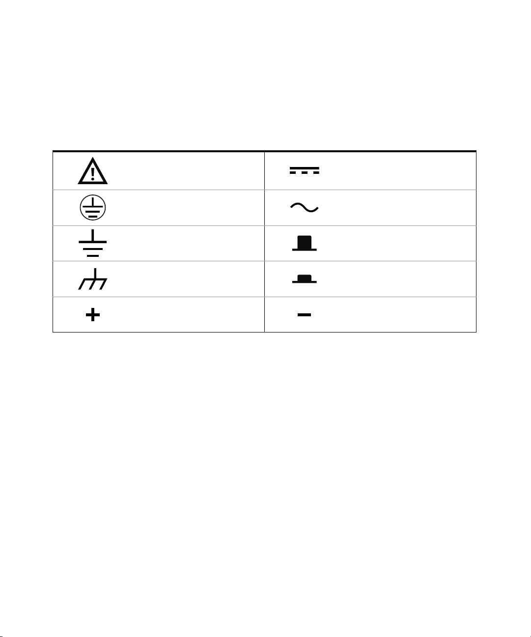
Safety Symbols
The following symbols on the instrument and in the documentation indicate
precautions which must be taken to maintain safe operation of the instrument.
Caution, risk of danger (refer to this
manual for specific Warning or Caution
information)
Protective conductor terminal Alternating current (AC)
Earth (ground) terminal Out position of a bi-stable push control
Frame or chassis terminal In position of a bi-stable push control
Positive binding post Negative binding post
Direct current (DC)
Keysight E3633A and E3634A User’s Guide 5
Page 6

Safety Considerations
CAUTION
CAUTION
CAUTION
Read the information below before using this instrument.
The following general safety precautions must be observed during all phases of
operation, service, and repair of this instrument. Failure to comply with these
precautions or with specific warnings elsewhere in this manual violates safety
standards for design, manufacture, and intended use of the instrument. Keysight
Technologies assumes no liability for the customer’s failure to comply with these
requirements.
BEFORE APPLYING POWER.
Verify that the product is set to match the available line voltage and that the
correct fuse is installed.
GROUND THE INSTRUMENT.
This product is a Safety Class I instrument (provided with a protective earth
terminal). To minimize shock hazard, the instrument chassis and cabinet
must be connected to an electrical ground. The instrument must be
connected to the AC power supply mains through a three-conductor power
cable, with the third wire firmly connected to an electrical ground (safety
ground) at the power outlet. Any interruption of the protective (grounding)
conductor or d isconnection of the protective earth terminal will cause a
potential shock hazard that could result in personal injury. If the instrument
is to be energized via an external autotransformer for voltage reduction, be
certain that the autotransformer common terminal is connected to the
neutral (earthed pole) of the AC power lines (supply mains).
DO NOT OPERATE IN AN EXPLOSIVE ATMOSPHERE.
Do not operate the instrument in the presence of flammable gases or fumes.
6 Keysight E3633A and E3634A User’s Guide
Page 7

CAUTION
KEEP AWAY FROM LIVE CIRCUITS.
CAUTION
CAUTION
NOTE
Operating personnel must not remove instrument covers. Component
replacement and internal adjustments must be made by qualified service
personnel. Do not replace components with power cable connected. Under
certain conditions, dangerous voltages may exist even with the power cable
removed. To avoid injuries, always disconnect power, discharge circuits and
remove external voltage sources before touching components.
DO NOT SERVICE OR ADJUST ALONE.
Do not attempt internal service or adjustment unless another person,
capable of rendering first aid and resuscitation, is present.
DO NOT SUBSTITUTE PARTS OR MODIFY INSTRUMENT.
Because of the danger of introducing additional hazards, do not install
substitute parts or perform any unauthorized modification to the instrument.
Return the instrument to a Keysight Technologies Sales and Service Office
for service and repair to ensure that safety features are maintained.
Instruments that appear damaged or defective should be made inoperative and
secured against unintended operation until they can be repaired by qualified
service personnel.
Keysight E3633A and E3634A User’s Guide 7
Page 8

Regulatory Markings
The CE marking is a legal compliance
marking of the European Community.
This CE marking shows that the
product complies with all the relevant
European Legal Directives.
The RCM mark is a registered
trademark of the Australian
Communications and Media Authority.
ICES/NMB-001 indicates that this ISM
device complies with the
Canadian ICES-001.
Cet appareil ISM est conforme a la
norme NMB-001 du Canada.
This instrument complies with the
WEEE Directive (2002/96/EC) marking
requirement. This affixed product label
indicates that you must not discard
this electrical or electronic product in
domestic household waste.
The CSA mark is a registered
trademark of the Canadian
Standards Association.
This symbol indicates the time period
during which no hazardous or toxic
substance elements are expected to
leak or deteriorate during normal use.
Forty years is the expected useful life
of the product.
This symbol is a South Korean Class A
EMC Declaration. This is a Class A
instrument suitable for professional
use and in electromagnetic
environment outside of the home.
8 Keysight E3633A and E3634A User’s Guide
Page 9

Waste Electrical and Electronic Equipment (WEEE) Directive
This instrument complies with the WEEE Directive marking requirement. This
affixed product label indicates that you must not discard this electrical or
electronic product in domestic household waste.
Product category:
With reference to the equipment types in the WEEE directive Annex 1, this
instrument is classified as a “Monitoring and Control Instrument” product.
The affixed product label is as shown below.
Do not dispose in domestic household waste.
To return this unwanted instrument, contact your nearest Keysight Service Center,
or visit http://about.keysight.com/en/companyinfo/environment/takeback.shtml
for more information.
Sales and Technical Support
To contact Keysight for sales and technical support, refer to the support links on
the following Keysight websites:
– www.keysight.com/find/powersupply
(product-specific information and support, software and
documentation updates)
– www.keysight.com/find/assist
(worldwide contact information for repair and service)
Keysight E3633A and E3634A User’s Guide 9
Page 10

THIS PAGE HAS BEEN INTENTIONALLY LEFT BLANK.
10 Keysight E3633A and E3634A User’s Guide
Page 11

Table of Contents
Certification . . . . . . . . . . . . . . . . . . . . . . . . . . . . . . . . . . . . . . . . . . . . . . . .3
Warranty Information . . . . . . . . . . . . . . . . . . . . . . . . . . . . . . . . . . . . . . . . 3
Limitation of Warranty . . . . . . . . . . . . . . . . . . . . . . . . . . . . . . . . . . . . . . .4
Exclusive Remedies . . . . . . . . . . . . . . . . . . . . . . . . . . . . . . . . . . . . . . . . .4
Assistance . . . . . . . . . . . . . . . . . . . . . . . . . . . . . . . . . . . . . . . . . . . . . . . . .4
Safety Symbols . . . . . . . . . . . . . . . . . . . . . . . . . . . . . . . . . . . . . . . . . . . . .5
Safety Considerations . . . . . . . . . . . . . . . . . . . . . . . . . . . . . . . . . . . . . . . .6
Regulatory Markings . . . . . . . . . . . . . . . . . . . . . . . . . . . . . . . . . . . . . . . . .8
Waste Electrical and Electronic Equipment (WEEE) Directive . . . . . . . . 9
Product category . . . . . . . . . . . . . . . . . . . . . . . . . . . . . . . . . . . . . . . . .9
Sales and Technical Support . . . . . . . . . . . . . . . . . . . . . . . . . . . . . . . . . . 9
List of Figures . . . . . . . . . . . . . . . . . . . . . . . . . . . . . . . . . . . . . . . . . . . . .17
List of Tables . . . . . . . . . . . . . . . . . . . . . . . . . . . . . . . . . . . . . . . . . . . . . . 19
1 General Information
Safety Considerations . . . . . . . . . . . . . . . . . . . . . . . . . . . . . . . . . . . . . . .22
Safety and EMC requirements . . . . . . . . . . . . . . . . . . . . . . . . . . . . . .22
Options and Accessories . . . . . . . . . . . . . . . . . . . . . . . . . . . . . . . . . . . .23
Options . . . . . . . . . . . . . . . . . . . . . . . . . . . . . . . . . . . . . . . . . . . . . . . .23
Accessories . . . . . . . . . . . . . . . . . . . . . . . . . . . . . . . . . . . . . . . . . . . .24
Description . . . . . . . . . . . . . . . . . . . . . . . . . . . . . . . . . . . . . . . . . . . . . . .25
Installation . . . . . . . . . . . . . . . . . . . . . . . . . . . . . . . . . . . . . . . . . . . . . . . 28
Initial inspection . . . . . . . . . . . . . . . . . . . . . . . . . . . . . . . . . . . . . . . . .28
Cooling and location . . . . . . . . . . . . . . . . . . . . . . . . . . . . . . . . . . . . .28
Product at a Glance . . . . . . . . . . . . . . . . . . . . . . . . . . . . . . . . . . . . . . . .31
The front panel at a glance . . . . . . . . . . . . . . . . . . . . . . . . . . . . . . . .31
Front-panel voltage and current limit settings . . . . . . . . . . . . . . . . .33
Display annunciators . . . . . . . . . . . . . . . . . . . . . . . . . . . . . . . . . . . . .34
The rear panel at a glance . . . . . . . . . . . . . . . . . . . . . . . . . . . . . . . . .35
Keysight E3633A and E3634A User’s Guide 11
Page 12

Input Power Requirements . . . . . . . . . . . . . . . . . . . . . . . . . . . . . . . . . . 36
Power-line cord . . . . . . . . . . . . . . . . . . . . . . . . . . . . . . . . . . . . . . . . . 36
Power-line voltage selection . . . . . . . . . . . . . . . . . . . . . . . . . . . . . . . 36
2Initial Operation
Preliminary Checkout . . . . . . . . . . . . . . . . . . . . . . . . . . . . . . . . . . . . . . . 40
Power-on Checkout . . . . . . . . . . . . . . . . . . . . . . . . . . . . . . . . . . . . . . . . 41
Output Checkout . . . . . . . . . . . . . . . . . . . . . . . . . . . . . . . . . . . . . . . . . . 43
Voltage output checkout . . . . . . . . . . . . . . . . . . . . . . . . . . . . . . . . . . 43
Current output checkout . . . . . . . . . . . . . . . . . . . . . . . . . . . . . . . . . . 45
3 Front-Panel Operation
Front-Panel Operation Overview . . . . . . . . . . . . . . . . . . . . . . . . . . . . . . 48
Constant Voltage Operation . . . . . . . . . . . . . . . . . . . . . . . . . . . . . . . . . 50
Constant Current Operation . . . . . . . . . . . . . . . . . . . . . . . . . . . . . . . . . 53
Storing and Recalling Operating States . . . . . . . . . . . . . . . . . . . . . . . . 56
Programming Overvoltage Protection . . . . . . . . . . . . . . . . . . . . . . . . . . 58
Programming Overcurrent Protection . . . . . . . . . . . . . . . . . . . . . . . . . . 63
Remote Voltage Sensing at the Front and Rear Terminals . . . . . . . . . . 67
CV regulation . . . . . . . . . . . . . . . . . . . . . . . . . . . . . . . . . . . . . . . . . . . 67
Output rating . . . . . . . . . . . . . . . . . . . . . . . . . . . . . . . . . . . . . . . . . . . 67
Output noise . . . . . . . . . . . . . . . . . . . . . . . . . . . . . . . . . . . . . . . . . . . 68
Stability . . . . . . . . . . . . . . . . . . . . . . . . . . . . . . . . . . . . . . . . . . . . . . . 68
Remote voltage sensing connections . . . . . . . . . . . . . . . . . . . . . . . . 68
Remote voltage sensing at the rear panel . . . . . . . . . . . . . . . . . . . . 70
Disabling the Output . . . . . . . . . . . . . . . . . . . . . . . . . . . . . . . . . . . . . . . 71
Disabling the Output Using an External Relay . . . . . . . . . . . . . . . . . . . 72
Knob Locking . . . . . . . . . . . . . . . . . . . . . . . . . . . . . . . . . . . . . . . . . . . . . 73
System-Related Operations . . . . . . . . . . . . . . . . . . . . . . . . . . . . . . . . . . 74
Self-test . . . . . . . . . . . . . . . . . . . . . . . . . . . . . . . . . . . . . . . . . . . . . . . 74
Error conditions . . . . . . . . . . . . . . . . . . . . . . . . . . . . . . . . . . . . . . . . . 75
Display control . . . . . . . . . . . . . . . . . . . . . . . . . . . . . . . . . . . . . . . . . . 77
Firmware revision query . . . . . . . . . . . . . . . . . . . . . . . . . . . . . . . . . . 78
12 Keysight E3633A and E3634A User’s Guide
Page 13

SCPI language version . . . . . . . . . . . . . . . . . . . . . . . . . . . . . . . . . . . .78
Remote Interface Configuration . . . . . . . . . . . . . . . . . . . . . . . . . . . . . . .79
Remote interface selection . . . . . . . . . . . . . . . . . . . . . . . . . . . . . . . .79
HPIB address . . . . . . . . . . . . . . . . . . . . . . . . . . . . . . . . . . . . . . . . . . .80
Baud rate selection (RS-232) . . . . . . . . . . . . . . . . . . . . . . . . . . . . . .80
Parity selection (RS-232) . . . . . . . . . . . . . . . . . . . . . . . . . . . . . . . . . .80
To set the HPIB Address . . . . . . . . . . . . . . . . . . . . . . . . . . . . . . . . . .81
To set the baud rate and parity (RS-232) . . . . . . . . . . . . . . . . . . . . .82
HPIB Interface Configuration . . . . . . . . . . . . . . . . . . . . . . . . . . . . . . . . .84
RS-232 Interface Configuration . . . . . . . . . . . . . . . . . . . . . . . . . . . . . . .85
RS-232 configuration overview . . . . . . . . . . . . . . . . . . . . . . . . . . . . .85
RS-232 Data Frame Format . . . . . . . . . . . . . . . . . . . . . . . . . . . . . . .85
Connection to a computer or terminal . . . . . . . . . . . . . . . . . . . . . . .86
DTR / DSR Handshake Protocol . . . . . . . . . . . . . . . . . . . . . . . . . . . .88
RS-232 troubleshooting . . . . . . . . . . . . . . . . . . . . . . . . . . . . . . . . . .89
Calibration Overview . . . . . . . . . . . . . . . . . . . . . . . . . . . . . . . . . . . . . . . .90
Calibration security . . . . . . . . . . . . . . . . . . . . . . . . . . . . . . . . . . . . . .90
Calibration count . . . . . . . . . . . . . . . . . . . . . . . . . . . . . . . . . . . . . . . .97
Calibration Message . . . . . . . . . . . . . . . . . . . . . . . . . . . . . . . . . . . . .98
4 Remote Interface Reference
SCPI Command Summary . . . . . . . . . . . . . . . . . . . . . . . . . . . . . . . . . .100
Simplified Programming Overview . . . . . . . . . . . . . . . . . . . . . . . . . . . .107
Using the APPLy command . . . . . . . . . . . . . . . . . . . . . . . . . . . . . . .107
Using the low-level commands . . . . . . . . . . . . . . . . . . . . . . . . . . . .107
Reading a query response . . . . . . . . . . . . . . . . . . . . . . . . . . . . . . . .108
Selecting a trigger source . . . . . . . . . . . . . . . . . . . . . . . . . . . . . . . .108
Power supply programming ranges . . . . . . . . . . . . . . . . . . . . . . . .109
Using the APPLy Command . . . . . . . . . . . . . . . . . . . . . . . . . . . . . . . . .111
Output Setting and Operation Commands . . . . . . . . . . . . . . . . . . . . .113
Triggering Commands . . . . . . . . . . . . . . . . . . . . . . . . . . . . . . . . . . . . .120
Trigger source choices . . . . . . . . . . . . . . . . . . . . . . . . . . . . . . . . . . .120
Triggering commands . . . . . . . . . . . . . . . . . . . . . . . . . . . . . . . . . . .122
Keysight E3633A and E3634A User’s Guide 13
Page 14

System-Related Commands . . . . . . . . . . . . . . . . . . . . . . . . . . . . . . . . 123
Calibration Commands . . . . . . . . . . . . . . . . . . . . . . . . . . . . . . . . . . . . 128
RS-232 Interface Commands . . . . . . . . . . . . . . . . . . . . . . . . . . . . . . . 131
The SCPI Status Registers . . . . . . . . . . . . . . . . . . . . . . . . . . . . . . . . . . 132
What is an event register? . . . . . . . . . . . . . . . . . . . . . . . . . . . . . . . 132
What is an enable register? . . . . . . . . . . . . . . . . . . . . . . . . . . . . . . 132
SCPI Status System . . . . . . . . . . . . . . . . . . . . . . . . . . . . . . . . . . . . . 133
The questionable status register . . . . . . . . . . . . . . . . . . . . . . . . . . . 134
The standard event register . . . . . . . . . . . . . . . . . . . . . . . . . . . . . . 135
The status byte register . . . . . . . . . . . . . . . . . . . . . . . . . . . . . . . . . . 136
Using Service Request (SRQ) and serial POLL . . . . . . . . . . . . . . . . 137
Using *STB? to read the status byte . . . . . . . . . . . . . . . . . . . . . . . . 138
Using the Message Available bit (MAV) . . . . . . . . . . . . . . . . . . . . . 138
To interrupt your bus controller using SRQ . . . . . . . . . . . . . . . . . . 138
To determine when a command sequence is completed . . . . . . . . 139
Using *OPC to signal when data is in the output buffer . . . . . . . . . 139
Status Reporting Commands . . . . . . . . . . . . . . . . . . . . . . . . . . . . . . . . 140
An Introduction to the SCPI Language . . . . . . . . . . . . . . . . . . . . . . . . 143
Command format used in this manual . . . . . . . . . . . . . . . . . . . . . . 144
Command separators . . . . . . . . . . . . . . . . . . . . . . . . . . . . . . . . . . . 145
Using the MIN and MAX parameters . . . . . . . . . . . . . . . . . . . . . . . 145
Querying parameter settings . . . . . . . . . . . . . . . . . . . . . . . . . . . . . 146
SCPI command terminators . . . . . . . . . . . . . . . . . . . . . . . . . . . . . . 146
IEEE-488.2 common commands . . . . . . . . . . . . . . . . . . . . . . . . . . 147
SCPI parameter types . . . . . . . . . . . . . . . . . . . . . . . . . . . . . . . . . . . 147
Halting an Output in Progress . . . . . . . . . . . . . . . . . . . . . . . . . . . . . . . 149
SCPI Conformance Information . . . . . . . . . . . . . . . . . . . . . . . . . . . . . . 150
SCPI confirmed commands . . . . . . . . . . . . . . . . . . . . . . . . . . . . . . . 150
Non-SCPI commands . . . . . . . . . . . . . . . . . . . . . . . . . . . . . . . . . . . 153
IEEE-488 Conformance Information . . . . . . . . . . . . . . . . . . . . . . . . . . 154
14 Keysight E3633A and E3634A User’s Guide
Page 15

5Error Messages
Error Messages . . . . . . . . . . . . . . . . . . . . . . . . . . . . . . . . . . . . . . . . . . .156
Execution Errors . . . . . . . . . . . . . . . . . . . . . . . . . . . . . . . . . . . . . . . . . .157
Self-Test Errors . . . . . . . . . . . . . . . . . . . . . . . . . . . . . . . . . . . . . . . . . . .165
Calibration Errors . . . . . . . . . . . . . . . . . . . . . . . . . . . . . . . . . . . . . . . . .167
6 Application Programs
Example Program for C and C++ . . . . . . . . . . . . . . . . . . . . . . . . . . . . .172
Diode.c . . . . . . . . . . . . . . . . . . . . . . . . . . . . . . . . . . . . . . . . . . . . . . .172
Example Program for Excel 97 . . . . . . . . . . . . . . . . . . . . . . . . . . . . . . .176
Diode Macro . . . . . . . . . . . . . . . . . . . . . . . . . . . . . . . . . . . . . . . . . . .178
Declaration for Windows 3.1 . . . . . . . . . . . . . . . . . . . . . . . . . . . . . .180
Declaration for Windows 9.5/NT 4.0 . . . . . . . . . . . . . . . . . . . . . . . .180
7Tutorial
Overview of Keysight E3633A and Keysight E3634A Operation . . . . .182
Output Characteristics . . . . . . . . . . . . . . . . . . . . . . . . . . . . . . . . . . . . .184
Unregulated state . . . . . . . . . . . . . . . . . . . . . . . . . . . . . . . . . . . . . .186
Unwanted signals . . . . . . . . . . . . . . . . . . . . . . . . . . . . . . . . . . . . . .186
Connecting the Load . . . . . . . . . . . . . . . . . . . . . . . . . . . . . . . . . . . . . .188
Output isolation . . . . . . . . . . . . . . . . . . . . . . . . . . . . . . . . . . . . . . . .188
Multiple loads . . . . . . . . . . . . . . . . . . . . . . . . . . . . . . . . . . . . . . . . .188
Remote voltage sensing . . . . . . . . . . . . . . . . . . . . . . . . . . . . . . . . .190
Load consideration . . . . . . . . . . . . . . . . . . . . . . . . . . . . . . . . . . . . .191
Extending the Voltage and Current Range . . . . . . . . . . . . . . . . . . . . .193
Series connections . . . . . . . . . . . . . . . . . . . . . . . . . . . . . . . . . . . . . .193
Parallel connections . . . . . . . . . . . . . . . . . . . . . . . . . . . . . . . . . . . .193
Remote Programming . . . . . . . . . . . . . . . . . . . . . . . . . . . . . . . . . . . . .194
Reliability . . . . . . . . . . . . . . . . . . . . . . . . . . . . . . . . . . . . . . . . . . . . . . . .196
Keysight E3633A and E3634A User’s Guide 15
Page 16

8Specifications
Performance Specifications . . . . . . . . . . . . . . . . . . . . . . . . . . . . . . . . . 198
Transient response time . . . . . . . . . . . . . . . . . . . . . . . . . . . . . . . . . 199
Command processing time . . . . . . . . . . . . . . . . . . . . . . . . . . . . . . . 199
OVP and OCP accuracy, ±(% of output + offset) . . . . . . . . . . . . . . 199
Activation time . . . . . . . . . . . . . . . . . . . . . . . . . . . . . . . . . . . . . . . . . 199
Supplemental Characteristics . . . . . . . . . . . . . . . . . . . . . . . . . . . . . . . 200
Remote sensing capability . . . . . . . . . . . . . . . . . . . . . . . . . . . . . . . 200
Temperature coefficient, ±(% of output + offset) . . . . . . . . . . . . . . 200
Stability, ±(% of output + offset) . . . . . . . . . . . . . . . . . . . . . . . . . . . 201
Output voltage overshoot . . . . . . . . . . . . . . . . . . . . . . . . . . . . . . . . 201
Programming language . . . . . . . . . . . . . . . . . . . . . . . . . . . . . . . . . . 201
State Storage Memory . . . . . . . . . . . . . . . . . . . . . . . . . . . . . . . . . . 201
Recommended calibration interval . . . . . . . . . . . . . . . . . . . . . . . . . 201
Output Terminal Isolation (maximum, from chassis ground) . . . . . 201
AC input ratings (selectable via rear panel selector . . . . . . . . . . . . 202
Maximum input power . . . . . . . . . . . . . . . . . . . . . . . . . . . . . . . . . . 202
Cooling . . . . . . . . . . . . . . . . . . . . . . . . . . . . . . . . . . . . . . . . . . . . . . 202
Operating temperature . . . . . . . . . . . . . . . . . . . . . . . . . . . . . . . . . . 202
Storage temperature . . . . . . . . . . . . . . . . . . . . . . . . . . . . . . . . . . . . 202
Environmental Conditions . . . . . . . . . . . . . . . . . . . . . . . . . . . . . . . . 202
Dimensions . . . . . . . . . . . . . . . . . . . . . . . . . . . . . . . . . . . . . . . . . . . 202
Weight . . . . . . . . . . . . . . . . . . . . . . . . . . . . . . . . . . . . . . . . . . . . . . . 203
Weight (MY53xx6xxx) . . . . . . . . . . . . . . . . . . . . . . . . . . . . . . . . . . . 203
16 Keysight E3633A and E3634A User’s Guide
Page 17

List of Figures
Figure 3-1 Recommended protection circuit
Figure 3-2 Remote voltage sensing connections . . . . . . . . . . . . .69
Figure 3-3 Rear local sensing connections . . . . . . . . . . . . . . . . . . . .70
Figure 7-1 Diagram of simple series power supply . . . . . . . . . . .182
Figure 7-2 Block diagram of the power supply
Figure 7-3 Ideal Constant Voltage Power Supply . . . . . . . . . . . .184
Figure 7-4 Ideal Constant Current Power Supply . . . . . . . . . . . .184
Figure 7-5 Output Characteristics . . . . . . . . . . . . . . . . . . . . . . . .185
Figure 7-6 Simplified diagram of common mode
Figure 7-7 Regulated power supply with remote sensing . . . . .190
Figure 7-8 Speed of response - programming up (full load) . . .194
Figure 7-9 Speed of response - programming down . . . . . . . . . 195
Figure 8-1 Dimensions of Keysight E3633A and E3634A
for battery charging . . . . . . . . . . . . . . . . . . . . . . . . .62
showing the isolation . . . . . . . . . . . . . . . . . . . . . .183
and normal mode sources of noise . . . . . . . . . . . .187
power supplies . . . . . . . . . . . . . . . . . . . . . . . . . . . .203
Keysight E3633A and E3634A User’s Guide 17
Page 18

THIS PAGE HAS BEEN INTENTIONALLY LEFT BLANK.
18 Keysight E3633A and E3634A User’s Guide
Page 19

List of Tables
Table 4-1 Keysight E3633A programming ranges . . . . . . . . . . .109
Table 4-2 Keysight E3634A Programming Ranges . . . . . . . . . . 110
Table 4-3 Bit Definitions - Questionable Status Register . . . . .134
Table 4-4 Bit Definitions – Standard Event Register . . . . . . . . .135
Table 4-5 Bit-Definitions - Status Byte Summary Register . . . .136
Table 7-1 Wire rating . . . . . . . . . . . . . . . . . . . . . . . . . . . . . . . . .188
Table 7-2 Slew rate . . . . . . . . . . . . . . . . . . . . . . . . . . . . . . . . . . .191
Table 8-1 Performance specifications . . . . . . . . . . . . . . . . . . . .198
Table 8-2 Supplemental Characteristics . . . . . . . . . . . . . . . . . .200
Keysight E3633A and E3634A User’s Guide 19
Page 20

THIS PAGE HAS BEEN INTENTIONALLY LEFT BLANK.
20 Keysight E3633A and E3634A User’s Guide
Page 21

Keysight E3633A and E3634A DC Power Supplies
User’s Guide
1 General Information
Safety Considerations 22
Options and Accessories 23
Description 25
Installation 28
Product at a Glance 31
This is the User’s guide for your Keysight E3633A and E3634A DC power supplies.
Unless otherwise stated, the information in this manual applies to both two
models.
This chapter provides a general description of your power supply. This chapter
also contains instructions for initial inspection, location and cooling for bench and
rack operation, selecting the power-line voltage, and connecting your power
supply to ac power.
21
Page 22

1General Information
Safety Considerations
This power supply is a Safety Class I instrument, which means that it has a
protective earth terminal. That terminal must be connected to earth ground
through a power source with a 3-wire ground receptacle.
Before installation or operation, check the power supply and review this manual
for safety markings and instructions. Safety information for specific procedures is
located at the appropriate places in this manual. See also Safety Considerations
at the beginning of this manual for general safety information.
Safety and EMC requirements
This power supply is designed to comply with the following safety and EMC
(Electromagnetic Compatibility) requirements:
– Low Voltage Directive (2006/95/EC)
– EMC Directive (2004/108/EC)
Safety
– IEC 61010-1:2001 / EN 61010-1:2001
– CAN/CSA-C22.2 No. 61010-1-04
– ANSI/UL61010-1:2004
EMC
– IEC61326-1:2005 / EN61326-1:2006
– Canada: ICES/NMB-001: Issue 4, June 2006
– Australia/New Zealand: AS/NZS CISPR 11:2004
– EN 55011(1991) Group 1, Class A/CISPR 11(1990): Limits and Methods of
Radio Interference Characteristics of Industrial, Scientific, and Medical (ISM)
Radio Frequency Equipment.
–ICES/NMB-001
This ISM device complies with Canadian ICES-001. Cet appareil ISM est
conforme à la norme NMB-001 du Canada.
22 Keysight E3633A and E3634A User’s Guide
Page 23

Options and Accessories
Options
Option 0EM, 0E3, and 0E9 determine which power-line voltage is selected at the
factory. The standard unit is configured for 115 Vac ± 10%, 47-63 Hz input
voltage.
For more information about changing the power-line voltage setting, see
“Power-line voltage selection” on page 36 in this chapter.
Option no. Description
0EM: 115 VAC ± 10%, 47-63 Hz Input
0E3: 230 VAC ± 10%, 47-63 Hz Input
0E9: 100 VAC ± 10%, 47-63 Hz Input
1CM: Rack mount kit (Keysight part number 5063-9243)
0L2: Extra English Manual set (local language manual files are included in the
CD-ROM (Keysight part number 5964-8251)
General Information 1
Keysight E3633A and E3634A User’s Guide 23
Page 24

1General Information
Accessories
The accessories listed below may be ordered from your local Keysight
Technologies Sales Office either with the power supply or separately.
Keysight part no. Description
10833A: GPIB cable, 1 meter (3.3 feet)
10833B: GPIB cable, 2 meter (6.6 feet)
34398A: RS-232, 9 pin (f) to 9 pin (f), 2.5 m (8.2 ft.) cable; plus 9 pin (m) to 25 pin (f)
34399A: RS-232 adapter kit (contains 4 adapters):
adapter
9 pin (m) to 25 pin (m) for use with PC or printer
9 pin (m) to 25 pin (f) for use with PC or printer
9 pin (m) to 25 pin (m) for use with modem
9 pin (m) to 9 pin (m) for use with modem
24 Keysight E3633A and E3634A User’s Guide
Page 25

Description
General Information 1
The Keysight E3633A and Keysight E3634A DC power supplies feature a
combination of programming capabilities and linear power supply performance
that makes them ideal for power systems applications. The power supply is
programmable locally from the front panel or remotely over the GPIB and RS-232
interfaces. This power supply has two ranges, allowing more voltage at a lower
current. An output range needed is selected from the front panel or over the
remote interfaces.
Operational features include:
– Dual range of single-output:
– 8V/20A and 20V/10A (Keysight E3633A)
– 25V/7A and 50V/4A (Keysight E3634A)
– Constant voltage (CV) or constant current (CC) operation
– Overvoltage protection (OVP) and overcurrent protection (OCP)
– Three storage locations (1 to 3) for user-defined operating states
– Automatic turn-on self-test
– Remote sensing for load voltage at the front or rear panel terminals
– User calibration from the front panel or over the remote interfaces
The front panel operation permits:
– Easy-to-use of knob control
– Output range selection
– Enabling or disabling OVP and OCP features
– Setting the OVP and OCP trip levels
– Clearing OVP and OCP conditions
– Setting and displaying the voltage and current limit values
– Saving and recalling operating states
– Returning the power supply to local mode from remote interface mode
– Retrieving/Scrolling error messages on the display
Keysight E3633A and E3634A User’s Guide 25
Page 26

1General Information
– Calibrating the power supply, including changing the calibration secure code
– Configuring the power supply for remote interfaces
– Enabling or disabling the output
When operated over the remote interface, the power supply can be both a listener
and a talker. Using an external controller, you can instruct the power supply to set
the output and to send the status data back over the GPIB or RS-232. Capabilities
include the following features:
– Voltage and current programming
– Voltage and current readback
– Present and stored status readback
– Programming syntax error detection
– Complete self-test
The front-panel VFD (Vacuum-Fluorescent Display) includes:
– Displaying actual values of output voltage and current (meter mode)
– Or displaying the limit values of voltage and current (limit mode)
– Checking the operating status from the annunciators
– Checking the type of error from the error codes (messages)
Connections to the power supply’s output and to chassis ground are made to
binding posts on the front panel and to the rear output terminals.
26 Keysight E3633A and E3634A User’s Guide
Page 27
General Information 1
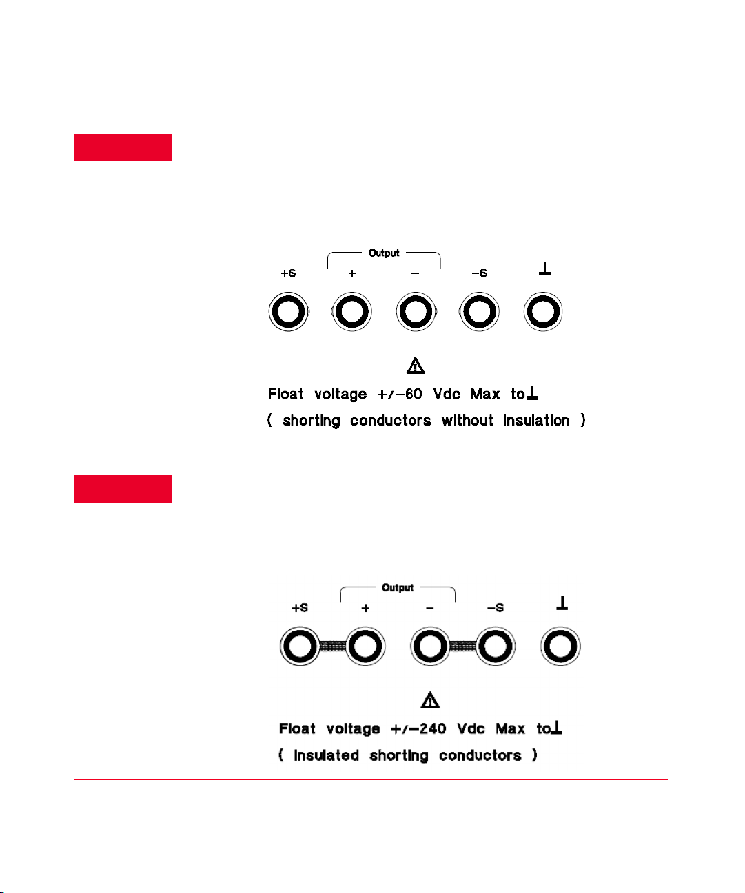
WARNING
WARNING
Floating the power supply output more than ±60 Vdc from the chassis
presents an electric shock hazard to the operator. Do not float the outputs
more than ±60 Vdc when metal shorting bars without insulation are used to
connect the (+) output to the (+) sense and the (-) output to the (-) sense
terminals.
Outputs can be floated to maximum of ±240 Vdc provided that the metal
shorting bars without insulation are either replaced with insulated
conductors or they are removed from the terminals so there is no operator
access to the output conductors without insulation. All field wiring insulation
must be adequate for the voltage present.
Keysight E3633A and E3634A User’s Guide 27
Page 28

1General Information
The power supply is shipped with a detachable, 3-wire grounding type power
cord.The ac line fuse is an extractor type on the rear panel. The power supply can
be calibrated from the front panel directly or with a controller over the GPIB or
RS-232 interface using calibration commands. Correction factors are stored in
nonvolatile memory and are used during output programming. Calibration from
the front panel or a controller eliminate the need to remove the top cover or even
the need to remove the power supply from your system cabinet. You can guard
against unauthorized calibration by using the “Secured” calibration protection
function.
28 Keysight E3633A and E3634A User’s Guide
Page 29

Installation
Initial inspection
General Information 1
When you receive your power supply, inspect it for any obvious damage that may
have occurred during shipment. If any damage is found, notify the carrier and the
nearest Keysight Sales Office immediately. Warranty information is shown in the
front of this manual.
Keep the original packing materials in case the power supply has to be returned to
Keysight Technologies in the future. If you return the power supply for service,
attach a tag identifying the owner and model number. Also include a brief
description of the problem.
Mechanical check
This check confirms that there are no broken keys or knob, that the cabinet and
panel surfaces are free of dents and scratches, and that the display is not
scratched or cracked.
Electrical check
Chapter 2 describes an initial operation procedure which, when successfully
completed, verifies to a high level of confidence that the power supply is
operating in accordance with its specifications. Detailed electrical verification
procedures are included in the Service Guide.
Cooling and location
Cooling
The power supply can operate without loss of performance within the temperature
range of 0 °C to 40 °C, and with derated output current from 40 °C to 55 °C. A fan
cools the power supply by drawing air through the rear panel and exhausting it
out the sides. Using a Keysight rack mount will not impede the flow of air.
Bench operation
Your power supply must be installed in a location that allows sufficient space at
the sides and rear of the power supply for adequate air circulation. The rubber
bumpers must be removed for rack mounting.
Keysight E3633A and E3634A User’s Guide 29
Page 30

1General Information
Rack mounting
The power supply can be mounted in a standard 19-inch rack cabinet using one of
three optional kits available. A rack-mounting kit for a single instrument is
available as Option 1CM (P/N 5063-9243). Installation instructions and hardware
are included with each rack-mounting kit. Any Keysight System II instrument of
the same size can be rack-mounted beside the Keysight E3633A or E3634A DC
power supply.
Remove the front and rear bumpers before rack-mounting the power supply.
To remove the rubber bumper, pull the bumper off from the top as there are
protrusions on the sides and bottom of the cover.
To rack mount a single instrument, order adapter kit 5063-9243.
30 Keysight E3633A and E3634A User’s Guide
Page 31

General Information 1
To rack mount two instruments of the same depth side-by-side, order lock-link
kit 5061-9694 and flange kit 5063-9214.
To install two instruments in a sliding support shelf, order support shel f
5063-9256, and slide kit 1494-0015.
Keysight E3633A and E3634A User’s Guide 31
Page 32

1General Information
Product at a Glance
The front panel at a glance
1 8V/20A range selection key (E3633A)
25V/7A range selection key (E3634A)
2 20V/10A range selection key (E3633A)
50V/4A range selection key (E3634A)
3 Overvoltage protection key 11 Control knob
4 Overcurrent protection key 12 Resolution selection keys
5 Display key limit 13 Voltage/current adjust selection key
6 Recall operating state key
7 Store operating state/Local key
8 Error/Calibrate key
9 I/O Configuration key
10 Output On/Off key
32 Keysight E3633A and E3634A User’s Guide
Page 33

General Information 1
1 8V/20A* or 25V/7A** range selection key Selects the 8V/20A or 25V/
7Arange and allows the full rated output to 8V/20A or 25V/7A.
2 20V/10A* or 50V/4A** range selection key Selects the 20V/10A or 50V/4A
range and allows the full rated output to 20V/10A or 50V/4A.
3 Overvoltage protection key Enables or disables the overvoltage protection
function, sets trip voltage level, and clears the overvoltage condition.
4 Overcurrent protection key Enables or disables the overcurrent protection
function, sets trip current level, and clears the overcurrent condition.
5 Display limit key Shows voltage and current limit values on the display and
allows knob adjustment for setting limit values.
6 Recall operating state key Recalls a previously stored operating state from
location “1”, “2”, or “3”.
7 Store operating state / Local key
[1]
Stores an operating state in location “1”,
“2”, or “3” / or returns the power supply to local mode from remote interface
mode.
8Error / Calibrate key
[2]
Displays error codes generated during operation,
self-test and calibration / or enables calibration mode (the power supply must
be unsecured before performing calibration). See Service Guide for more
details on calibration.
9 I/O Configuration / Secure key
[3]
Configures the power supply for remote
interfaces / or secure or unsecure the power supply for calibration. See Service
Guide for more details on how to secure or unsecure the power supply.
10 Output On/Off key Enables or disables the power supply output. This key
toggles between on and off.
11 Control knob Increases or decreases the value of the blinking digit by turning
clockwise or counter clockwise.
12 Resolution selection keys Move the blinking digit to the right or left.
13 Voltage/current ad just selection key Selects the knob control function for
voltage or current adjustment.
[1] The key can be used as the “Local” key when the power supply is in the remote interface mode.
[2] You can enable the “calibration mode” by holding down this key when you turn on the power
supply.
[3] You can use it as the “Secure” or “Unsecure” key when the power supply is in the calibration mode.
Keysight E3633A and E3634A User’s Guide 33
Page 34

1General Information
NOTE
Front-panel voltage and current limit settings
You can set the voltage and current limit values from the front panel using the
following method.
Use the voltage/current adjust selection key, the resolution selection keys, and the control knob to
change the voltage and current limit values.
1 Select the desired range using the range selection keys after turning on the
power supply.
2 Press the key to show the limit values on the display.
3 Move the blinking digit to the appropriate position using the resolution
selection keys and change the blinking digit value to the desired voltage limit
by turning the control knob. If the display limit times out, press the key
again.
4 Set the knob to current control mode by pressing the key.
5 Move the blinking digit to the appropriate position using the resolution
selection keys and change the blinking digit value to the desired current limit
by turning the control knob.
6 Press the key to enable the output. After about 5 seconds, the display will
go to output monitoring mode automatically to display the voltage and current
at the output or the display will go to output monitoring mode immediately by
pressing the key again.
All front panel keys and controls can be disabled with remote interface
commands. The Keysight E3633A and Keysight E3634A must be in "Local" mode
for the front panel keys and controls to function.
34 Keysight E3633A and E3634A User’s Guide
Page 35

Display annunciators
Adrs Power supply is addressed to listen or talk over a remote interface.
Rmt Power supply is in remote interface mode.
8V Shows the 8V/20A range is selected. (Keysight E3633A model)
20V Shows the 20V/10A range is selected. (Keysight E3633A model)
25V Shows the 25V/7A range is selected. (Keysight E3634A model)
50V Shows the 50V/4A range is selected. (Keysight E3634A model)
The overvoltage protection function is enabled when the annunciator turns on or the
OVP
OCP
CAL The power supply is in calibration mode.
Limit The display shows the limit values of voltage and current.
overvoltage protection circuit has caused the power supply to shutdown when the
annunciator blinks.
The overcurrent protection function is enabled when the annunciator turns on or the
overcurrent protection circuit has caused the power supply to shutdown when the
annunciator blinks.
General Information 1
ERROR
OFF The output of the power supply is disabled (See page 52 for more information).
Unreg The output of the power supply is unregulated (output is neither CV nor CC).
CV The power supply is in constant voltage mode.
CC The power supply is in constant current mode.
Hardware or remote interface command errors are detected and the error bit has not
been cleared.
To review the display annunciators, hold down key as you turn on the power
supply.
Keysight E3633A and E3634A User’s Guide 35
Page 36

1General Information
The rear panel at a glance
1 Power-line voltage setting 5 GPIB (IEEE-488) interface connection
2 Power-line fuse-holder assembly 6 RS-232 interface connector
3 AC inlet 7 Rear output terminals
4 Power-line module
Use the front-panel key to:
– Select the GPIB or RS-232 interface (see chapter 3).
– Set the GPIB bus address (see chapter 3).
– Set the RS-232 baud rate and parity (see chapter 3).
36 Keysight E3633A and E3634A User’s Guide
Page 37

Input Power Requirements
You can operate your power supply from a nominal 100 V, 115 V, or 230 V single
phase ac power source at 47 to 63 Hz. An indication on the rear panel shows the
nominal input voltage set for the power supply at the factory. If necessary, you
can change the power-line voltage setting according to the instructions on the
next page
Power-line cord
The power supply is shipped from the factory with a power-line cord that has a
plug appropriate for your location. Contact the nearest Keysight Sales and Service
Office if the wrong power-line cord is included with your power supply. Your power
supply is equipped with a 3-wire grounding type power cord; the third conductor
being the ground. The power supply is grounded only when the power-line cord is
plugged into an appropriate receptacle. Do not operate your power supply
without adequate cabinet ground connection.
Power-line voltage selection
General Information 1
Power-line voltage selection is accomplished by adjusting two components:
power-line vol tage selector and power-line fuse on the power-line module of the
rear panel. To change the power-line voltage, proceed as follows:
Keysight E3633A and E3634A User’s Guide 37
Page 38

1General Information
1 Remove the power cord. Remove the fuse-holder
assembly with a flat-blade screwdriver from the rear panel.
3 Rotate the power-line vol tage selector until the correct
voltage appears.
2 Install the correct line fuse. Remove the power-line
voltage selector from the power-line module.
4 Replace the power-line voltage selector and the
fuse-holder assembly in the rear panel.
38 Keysight E3633A and E3634A User’s Guide
Page 39

Keysight E3633A and E3634A DC Power Supplies
NOTE
User’s Guide
2 Initial Operation
Preliminary Checkout 40
Power-on Checkout 41
Output Checkout 43
There are three basic tests in this chapter. The automatic power-on test includes a
self-test that checks the internal microprocessors and allows the user visually to
check the display. The output check ensures that the power supply develops its
rated outputs and properly responds to operation from the front panel. For
complete performance and/or verification tests, refer to the Service Guide.
This chapter is intended for both the experienced and the inexperienced user
because it calls attention to certain checks that should be made prior to
operation.
Throughout this chapter the key to be pressed is shown in the left margin.
39
Page 40

2Initial Operation
Preliminary Checkout
The following steps help you verify that the power supply is ready for use.
1 Check the list of supplied items.
Verify that you have received the following items with your power supply. If
anything is missing, contact your nearest Keysight Technologies Sales Office.
– One power cord for your location.
– This User’s Guide.
– One Service Guide.
– Certificate of Calibration.
2 Verify the power-line voltage setting on the rear panel.
The power-line voltage is set to the proper value for your country when the
power supply is shipped from the factory. Change the voltage setting if it is not
correct. The settings are: 100, 115, or 230 Vac.
3 Verify that the correct power-line fuse is installed.
The correct fuse is installed for your country when the power supply is shipped
from the factory. For 100 or 115 Vac operation, you must use a 6.3 AT fuse. For
230 Vac operation, you must use a 3.15 AT fuse.
4 Connect the power-line cord and turn on your power supply.
The front-panel display will light up and a power-on self-test occurs
automatically when you turn on the power supply.
See “Power-line voltage selection” on page 37 if you need to change the
power-line voltage or the power-line fuse.
To replace the 6.3 AT fuse, order Keysight part number 2110-1030.
To replace the 3.15 AT fuse, order Keysight part number 2110-1031.
40 Keysight E3633A and E3634A User’s Guide
Page 41

Power-on Checkout
The power-on test includes an automatic self-test that checks the internal
microprocessors and allows the user visually to check the display. You will
observe the following sequence on the display after pressing the front panel
power switch to on.
1 The front-panel display will light up briefly while the instrument performs
its power-on sel f-test.
To review the power-on display with all annunciators turned on, hold down
key as you turn on the power supply.
2 The GPIB address or RS-232 is also displayed for about one second.
ADDR (or RS-232)
The GPIB address is set to “5” when the power supply is shipped from the
factory for remote interface configuration. If this is not the first time the power
supply is turned on, a different interface (RS-232) or a different GPIB address
may appear. See “Remote Interface Configuration” on page 79 if you need to
change the remote interface configuration.
Initial Operation 2
3The “8V”
[1]
or “25V”
[2]
, “OVP”, “OCP” and “OFF” annunciators are on. All
others are off.
The power supply will go into the power-on / reset state; the output is disabled
(the OFF annunciator turns on); the 8V/20A
(the 8V
[1]
or 25V
[2]
annunciator turns on); and the knob is selected for voltage
[1]
or 25V/7A
[2]
range is selected
control. Notice that the OVP and OCP annunciator also turn on.
[1] For Keysight E3633A Model
[2] For Keysight E3634A Model
Keysight E3633A and E3634A User’s Guide 41
Page 42

2Initial Operation
NOTE
4 Enable the outputs.
The OFF annunciator turns off and the 8V
annunciators are lit. The blinking digit can be adjusted by turning the knob.
Notice that the display is in the meter mode. “Meter mode” means that the
display shows the actual output voltage and current.
If the power supply detects an error during power-on self-test, the ERROR
annunciator will turn on. See “Error Messages” on page 156
[1]
or 25V
[2]
, OVP, OCP, and CV
[1] For Keysight E3633A Model
[2] For Keysight E3634A Model
42 Keysight E3633A and E3634A User’s Guide
Page 43

Output Checkout
The following procedures check to ensure that the power supply develops its
rated outputs and properly responds to operation from the front panel. For
complete performance and verification tests, refer to the Service Guide.
For each step, use the keys shown on the left margins.
Voltage output checkout
The following steps verify basic voltage functions with no load
1Turn on the power supply
The power supply will go into the power-on / reset state; the output is disabled
(the OFF annunciator turns on); the 8V/20A
(the 8V
control.
2 Enable the outputs.
The OFF annunciator turns off and the 8V
annunciators are lit. The blinking digit can be adjusted by turning the knob.
Notice that the display is in the meter mode. “Meter mode” means that the
display shows the actual output voltage and current.
[1]
or 25V
Initial Operation 2
[1]
or 25V/7A
[2]
annunciator turns on); and the knob is selected for voltage
[1]
or 25V
[2]
range is selected
[2]
OVP, OCP, and CV
3 Check that the front-panel voltmeter properly responds to knob control for
the 8V/20A
[1]
or 25V/7A
[2]
range.
Turn the knob clockwise or counter clockwise to check that the voltmeter
responds to knob control and the ammeter indicates nearly zero.
4 Ensure that the voltage can be adjusted from zero to the full rated value.
Adjust the knob until the voltmeter indicates 0 volts and then adjust the knob
until the voltmeter indicates “8.0 volts”
[1] For Keysight E3633A Model
[2] For Keysight E3634A Model
[1]
or “25.0 volts”
[2]
Keysight E3633A and E3634A User’s Guide 43
Page 44

2Initial Operation
NOTE
You can use the resolution selection keys to move the blinking digit to the right
or left when setting the voltage.
44 Keysight E3633A and E3634A User’s Guide
Page 45

Current output checkout
The following steps check basic current functions with a short across the power
supply’s output.
1Turn on the power supply.
The power supply will go into the power-on / reset state; the output is disabled
(the OFF annunciator turns on); the 8V/20A
(the 8V
[1]
or 25V
control.
2 Connect a short across (+) and (-) output terminals with an insulated test
lead.
Use a wire size sufficient to handle the maximum current (See Table 7-1).
3 Enable the output
The OFF annunciator turns off and the 8V
annunciators are lit. The CV or CC annunciator turns on depending on the
resistance of the test lead. The blinking digit can be adjusted by turning the
knob. Notice that the display is in the meter mode. “Meter mode” means that
the display shows the actual output voltage and current.
[2]
Initial Operation 2
[1]
or 25V/7A
[2]
range is selected
annunciator turns on); and the knob is selected for voltage
[1]
or 25V
[2]
, OVP, and OCP
4 Adjust the voltage limit to 1.0 volt
Set the display to the limit mode (the Limit annunciator will be blinking).
Adjust the voltage limit to 1.0 volt to assure CC operation. The CC annunciator
will turn on. To go back to normal mode, press the key again or let the
display time out for several seconds.
[1] For Keysight E3633A Model
[2] For Keysight E3634A Model
Keysight E3633A and E3634A User’s Guide 45
Page 46

2Initial Operation
NOTE
NOTE
5 Set the knob to the current control to check that the front-panel ammeter
properly responds to knob control.
Turn the knob clockwise or counter clockwise when the display is in the meter
mode (the Limit annunciator is off). Check that the ammeter responds to knob
control and the voltmeter indicates nearly zero (the voltmeter will show the
voltage drop caused by the test lead).
6 Ensure that the current can be adjusted from zero to the full rated value.
Adjust the knob until the ammeter indicates 0 amps and then until the
ammeter indicates 20.0 amps
7 Turn off the power supply and remove the short from the output.
You can use the resolution selection keys to move the blinking digit to the right
or left when setting the current.
If an error has been detected during the output checkout procedures, the ERROR
annunciator will turn on. See “Error Messages” on page 156.
[1]
or 7.0 amps
[2]
.
[1] For Keysight E3633A Model
[2] For Keysight E3634A Model
46 Keysight E3633A and E3634A User’s Guide
Page 47

Keysight E3633A and E3634A DC Power Supplies
NOTE
User’s Guide
3 Front-Panel Operation
Front-Panel Operation Overview 48
Constant Voltage Operation 50
Constant Current Operation 53
Storing and Recalling Operating States 56
Programming Overvoltage Protection 58
Programming Overcurrent Protection 63
Remote Voltage Sensing at the Front and Rear Terminals 67
Disabling the Output 71
Disabling the Output Using an External Relay 72
Knob Locking 73
System-Related Operations 74
Remote Interface Configuration 79
HPIB Interface Configuration 84
RS-232 Interface Configuration 85
Calibration Overview 90
So far you have learned how to install your power supply and perform initial
operation. During the initial operation, you were briefly introduced to operating
from the front panel as you learned how to check basic voltage and current
functions. This chapter will describe in detail the use of these front-panel keys and
show how they are used to accomplish power supply operation.
Throughout this chapter the key to be pressed is shown in the left margin.
See “Error Messages” on page 156 if you encounter any errors during
front-panel operation.
47
Page 48

3 Front-Panel Operation
Front-Panel Operation Overview
The following section describes an overview of the front-panel keys before
operating your power supply.
– The power supply is shipped from the factory configured in the front-panel
operation mode. At power-on, the power supply is automatically set to operate
in the front-panel operation mode. When in this mode, the front-panel keys
can be used. When the power supply is in remote operation mode, you can
return to front-panel operation mode at any time by pressing the (Local)
key if you did not previously send the front-panel lockout command. A change
between front-panel and remote operation modes will not result in a change in
the output parameters
– The power supply has two output ranges. This feature allows more voltage at a
lower current or more current at a lower voltage. The desired output range is
selected from the front panel or over the remote interfaces. The 8V or 20V for
the E3633A and 25V or 50V for the E3634A annunciator indicates the
presently selected range.
– When you press key (the Limit annunciator blinks), the display of the
power supply goes to the limit mode and the present limit values will be
displayed. In this mode, you can also observe the change of the limit values
when adjusting the knob. If you press the key again or let the display
time-out after several seconds, the power supply will return the display to the
meter mode (the Limit annunciator turns off). In this mode, the actual output
voltage and current will be displayed.
– The output of the power supply can be enabled or disabled from the front
panel by pressing key. When the output is off, the OFF annunciator turns
on and the output is disabled.
48 Keysight E3633A and E3634A User’s Guide
Page 49

Front-Panel Operation 3
– The display provides the present operating status of the power supply with
annunciators and also informs the user of error codes. For example, the power
[1]
supply is operating in CV mode in the 8V/20A
or 25V/7A
controlled from the front panel, then the CV and 8V
[1]
[2]
or 25V
range and
[2]
annunciators
will turn on. If, however, the power supply is remotely controlled, the Rmt
annunciator will also turn on, and when the power supply is being addressed
over HPIB interface, the Adrs annunciator will turn on. See “Display
annunciators” on page 35 for more information.
[1] For Keysight E3633A Model
[2] For Keysight E3634A Model
Keysight E3633A and E3634A User’s Guide 49
Page 50

3 Front-Panel Operation
NOTE
Constant Voltage Operation
To setup the power supply for constant voltage (CV) operation, proceed as
follows.
– Front-panel operation:
1 Connect a load to the output terminals
With the power-off, connect a load to the (+) and (-) output terminals.
2 Turn on the power supply
The power supply will go into the power-on / reset state; the output is
disabled (the OFF annunciator turns on); the 8V/20A
is selected (the 8V
selected for voltage control. Press
power supply in the 20V/10A* or 50V/4A** range before proceeding to the
next step. The 20V
[1]
or 25V
[1]
or 50V
[1]
or 25V/7A
[2]
annunciator turns on); and the knob is
[1]
or
[2]
annunciator turns on.
[2]
key to operate the
[2]
range
3 Set the display to the limit mode
Notice that the Limit annunciator blinks, indicating that the display is in the
limit mode. When the display is in the limit mode, you can see the voltage
and current limit values of the power supply.
In constant voltage mode, the voltage values between the meter and limit
modes are the same, but the current values are not. Moreover, if the display is in
the meter mode, you cannot see the change of current limit value when
adjusting the knob. We recommend that you should set the display to “limit”
mode to see the change of current limit value in the constant voltage mode
whenever adjusting the knob.
[1] For Keysight E3633A Model
[2] For Keysight E3634A Model
50 Keysight E3633A and E3634A User’s Guide
Page 51

Front-Panel Operation 3
NOTE
4 Adjust the knob for the desired current limit.
Check that the Limit annunciator still blinks. Set the knob for current
control. The second digit of the ammeter will be blinking. The blinking digit
can be changed using the resolution selection keys and the blinking digit
can be adjusted by turning the knob. Adjust the knob to the desired current
limit.
5 Adjust the knob for the desired output voltage.
Check that the Limit annunciator still blinks. Set the knob for voltage
control. The second digit of the voltmeter will be blinking. Change the
blinking digit using the resolution selection keys and adjust the knob to the
desired output voltage.
6 Return to the meter mode.
Press key or let the display time-out after several seconds to return to
the meter mode. Notice that the Limit annunciator turns off and the
displays shows “OUTPUT OFF” message.
7 Enable the output.
The OFF annunciator turns off and the 8V
[1]
(or 25V
[2]
) or 20V
[1]
(or 50V
[2]
),
OVP, OCP and CV annunciators are lit. Notice that the display is in the
meter mode. In the meter mode, the display shows the actual output
voltage and current.
Refer to “Programming Overvoltage Protection” on page 58 and
“Programming Overcurrent Protection” on page 63 for more information on
OVP and OCP annunciators.
You can use the resolution selection keys to move the blinking digit to the right
or left when setting voltage.
[1] For Keysight E3633A Model
[2] For Keysight E3634A Model
Keysight E3633A and E3634A User’s Guide 51
Page 52

3 Front-Panel Operation
NOTE
NOTE
8 Verify that the power supply is in the constant voltage mode.
If you operate the power supply in the constant voltage (CV) mode, verify
that the CV annunciator is lit. If the CC annunciator is lit, choose a higher
current limit.
During actual CV operation, if a load change causes the current limit to be
exceeded, the power supply will automatically crossover to the constant current
mode at the preset current limit and the output voltage will drop
proportionately.
– Remote interface operation:
CURRent {<current>|MIN|MAX} Set the current
VOLTage {<voltage>|MIN|MAX} Set the voltage
OUTput ON Enable the output
You can use the resolution selection keys to move the blinking digit to the right
or left when setting voltage.
52 Keysight E3633A and E3634A User’s Guide
Page 53

Constant Current Operation
NOTE
To set up the power supply for constant current (CC) operation, proceed as
follows.
– Front-panel operation:
1 Connect a load to the output terminals.
With power-off, connect a load to the (+) and (-) output terminals.
2 Turn on the power supply
The power supply will go into the power-on / reset state; the output is
disabled (the OFF annunciator turns on); the 8V/20A
is selected (the 8V
selected for voltage control.
To operate the power supply in the 20V/10A
[1]
or
[2]
50V
annunciator turns on.
Front-Panel Operation 3
[1]
or 25V/7A
[1]
or 25V
[2]
key before proceeding to the next step. The 20V
[2]
annunciator turns on); and the knob is
[1]
or 50V/4A
[2]
range, press
[2]
range
[1]
or
3 Set the display to the limit mode.
Notice that the Limit annunciator blinks, indicating that the display is in the
limit mode. When the display is in the limit mode, you can see the voltage
and current limit values of the selected supply.
In constant current mode, the current values between the meter mode and limit
mode are the same, but the voltage values are not. Moreover, if the d isplay is in
the meter mode, you cannot see the change of voltage limit value when
adjusting the knob. We recommend that you should set the display to “limit”
mode to see the change of voltage limit value in the constant current mode
whenever adjusting the knob.
[1] For Keysight E3633A Model
[2] For Keysight E3634A Model
Keysight E3633A and E3634A User’s Guide 53
Page 54

3 Front-Panel Operation
NOTE
4 Adjust the knob for the desired voltage limit.
Check that the Limit annunciator still blinks and the second digit of
voltmeter blinks to indicate the knob is selected for voltage control.The
blinking digit can be changed using the resolution keys and the blinking
digit can be adjusted by turning the knob. Adjust the knob for the desired
voltage limit.
5 Adjust the knob for the desired output current.
Check that the Limit annunciator still blinks. Set the knob for current
control. The second digit of the ammeter will be blinking. Change the
blinking digit using the resolution selection keys and adjust the knob to the
desired output current.
6 Return to the meter mode.
Press key or let the display time-out after several seconds to return to
the meter mode. Notice that the Limit annunciator turns off and the display
shows “OUTPUT OFF” message.
7 Enable the output.
The OFF annunciator turns off and the 8V
[1]
(or 25V
[2]
) or 20V
[1]
(or 50V
[2]
),
OVP, OCP and CC annunciators are lit. Notice that the display is in the
meter mode. In the meter mode, the display shows the actual output
voltage and current.
Refer to “Programming Overvoltage Protection” on page 58 and
“Programming Overcurrent Protection” on page 63 for more information on
OVP and OCP annunciators.
You can use the resolution selection keys to move the blinking digit to the right
or left when setting the voltage.
[1] For Keysight E3633A Model
[2] For Keysight E3634A Model
54 Keysight E3633A and E3634A User’s Guide
Page 55

Front-Panel Operation 3
NOTE
NOTE
8 Verify that the power supply is in the constant current mode.
If you operate the power supply in the constant current (CC) mode, verify
that the CC annunciator is lit. If the CV annunciator is lit, choose a higher
voltage limit.
During actual CC operation, if a load change causes the voltage limit to be
exceeded, the power supply will automatically crossover to constant voltage
mode at the preset voltage limit and the output current will drop
proportionately.
– Remote interface operation:
CURRent {<current>|MIN|MAX} Set the current
VOLTage {<voltage>|MIN|MAX} Set the voltage
OUTput ON Enable the output
You can use the resolution selection keys to move the blinking digit to the right
or left when setting voltage.
Keysight E3633A and E3634A User’s Guide 55
Page 56

3 Front-Panel Operation
Storing and Recalling Operating States
You can store up to three different operating states in non-volatile memory. This
also enables you to recall the entire instrument configuration with just a few key
presses from the front panel.
The memory locations are supplied with the reset states from the factory for
front-panel operation. Refer to the description of “*RST” on page 126 for more
information. The following steps show you how to store and recall an operating
state.
– Front-panel operation:
1 Set up the power supply for the desired operating state.
The storage feature “remembers” output range selection, the limit value
settings of voltage and current, output on/off state, OVP and OCT on/off
state and OVP and OCP trip levels.
2Turn on the storage mode.
Three memory locations (numbered 1, 2 and 3) are available to store the
operating states. The operating states are stored in non-volatile memory
and are remembered when being recalled.
STORE 1
This message appears on the display for approximately 3 seconds.
3 Store the operating state in memory location “3”.
Turn the knob to the right to specify the memory location 3.
STORE 3
To cancel the store operation, let the display time-out after about 3
seconds or press any other function key except the ion key except the
key. The power supply returns to the normal operating mode and to the
function pressed. Save the operating state.
56 Keysight E3633A and E3634A User’s Guide
Page 57

Front-Panel Operation 3
4 Save the operating state.
The operating state is now stored. To recall the stored state, go to the
following steps.
DONE
5Turn on the recall mode.
Memory location “1” will be displayed in the recall mode.
RECALL 1
This message appears on the display for approximately 3 seconds.
6 Recall the stored operating state.
Turn the knob to the right to change the displayed storage location to 3.
RECALL 3
If this setting is not followed within 3 seconds with key stroke, the
power supply returns to normal operating mode and will not recall the
instrument state 3 from memory.
7 Restore the operating state.
The power supply should now be configured in the same state as when you
stored the state on the previous steps.
DONE
This message appears on the display for approximately 1 second.
– Remote interface operation:
*SAL {1|2|3} Store an operating state to a specified location
*RCL {1|2|3} Recall a previously stored state from a specified location
Keysight E3633A and E3634A User’s Guide 57
Page 58

3 Front-Panel Operation
Programming Overvoltage Protection
Overvoltage protection guards the load against output voltages that reach a
specified value greater than the programmed protection level. It is accomplished
by shorting the output via an internal SCR when the trip level is set to equal or
greater than 3 volts, or by programming the output to 1 volt when the trip level is
set to less than 3 volts.
The following steps show how to set the OVP trip level, how to check OVP
operation, and how to clear overvoltage condition.
– Front-panel operation:
Setting the OVP level and enable the OVP circuit
1 Turn on the power supply.
The power supply will go into the power-on / reset state; the output is disabled
(the OFF annunciator turns on); the 8V/20A
(the 8V
control.
[1]
or 25V
[2]
annunciator turns on); and the knob is selected for voltage
[1]
or 25V/7A
[2]
range is selected
2 Enable the output.
The OFF annunciator turns off and the display will go to the meter mode.
3 Enter the OVP menu and set the trip level.
LEVEL 22.0V (E3633A)
LEVEL 55.0V (E3634A)
You will see the above message on the display when you enter the OVP menu.
Adjust the control knob for the desired OVP trip level.
Note that you cannot set the trip levels to lower than 1.0 volt.
[1] For Keysight E3633A Model
[2] For Keysight E3634A Model
58 Keysight E3633A and E3634A User’s Guide
Page 59

Front-Panel Operation 3
4 Enable the OVP circuit.
OVP ON
You will see the above message after pressing key.
5 Exit the OVP menu.
CHANGED
The “CHANGED” message is highlighted for a second to show that the new
OVP trip level is now in effect. If the OVP settings are not changed, “NO
CHANGE” will be displayed. The power supply will exit the OVP menu and the
display will return to the meter mode. Check that the OVP annunciator turns
on.
Checking OVP operation
To check OVP operation, raise the output voltage to near the trip point. Then very
gradually increase the output by turning the knob until the OVP circuit trips. This
will cause the power supply output to drop to near zero, the OVP annunciator to
blink, and the CC annunciator to turn on. The “OVP TRIPPED” message also
appears on the display.
Clearing the overvoltage condition
When the OVP condition occurs (the “OVP TRIPPED” message is shown on the
display), the OVP annunciator blinks. When it was caused by an external voltage
source such as a battery, disconnect it first. Clear the overvoltage condition by
adjusting output voltage level or by adjusting OVP trip level.
The following steps show how to clear the overvoltage condition and get back to
normal mode operation. In the following steps, the display will go back to “OVP
TRIPPED” if you let the display time out after about several seconds.
Keysight E3633A and E3634A User’s Guide 59
Page 60

3 Front-Panel Operation
– Adjust the output voltage level
1 Lower the output voltage level.
Lower the output voltage level below the OVP trip point after pressing
key. The OVP and Limit annunciators are blinking.
2 Move to the clear mode.
Press key twice to move to the OVP CLEAR mode. The “OVP ON”
message appears on the display. Turn the knob to the right until the above
message appears on the display.
3 Clear the overvoltage condition and exit this menu.
Now, when you press key again, the “DONE” message is displayed for
a second and the OVP annunciator will not blink any more. The output will
return to meter mode.
OVP CLEAR
60 Keysight E3633A and E3634A User’s Guide
Page 61

Front-Panel Operation 3
NOTE
– Adjust OVP trip level
1 Raise the OVP trip level.
Press key and turn the knob to raise the OVP trip level.
2 Move to the OVP CLEAR mode.
OVP CLEAR
Press key to move the OVP clear mode. The “OVP ON” message
appears on the display. Turn the knob to the right until the above message
appears on the display.
3 Clear the overvoltage cond ition and exit this menu.
Now, when you press key again, the “DONE” message is displayed for
a second and the OVP annunciator will not blink any more. The output will
return to the meter mode.
– Remote interface operation:
VOLT:PROT {<voltage>|MIN|MAX} Set the OVP level
VOLT:PROT:STAT|{OFF|ON} Disable or enable the OVP circuit
VOLT:PROT:CLE Clear the tripper OVP circuit
The power supply’s OVP circuit contains a crowbar SCR, which effectively shorts
the output of the power supply whenever the overvoltage condition occurs. If
external voltage source such as a battery is connected across the output, and
the overvoltage condition inad vertently occurs, the SCR will continuously sink a
large current from the source; possibly damaging the power supply. To avoid this
a diode must be connected in series with the output as shown in Figure 3-1 on
next page.
Keysight E3633A and E3634A User’s Guide 61
Page 62

3 Front-Panel Operation
Figure 3-1 Recommended protection circuit for battery charging
62 Keysight E3633A and E3634A User’s Guide
Page 63

Programming Overcurrent Protection
Overcurrent protection guards the load against output currents that reach a
specified value greater than the programmed protection level. It is accomplished
by programming the output current to zero.
The following steps show how to set the overcurrent protection trip level, how to
check OCP operation and how to clear overcurrent condition.
– Front-panel operation:
Setting the OCP level and enable the OCP circuit
1Turn on the power supply.
The power supply will go into the power-on / reset state; the output is disabled
(the OFF annunciator turns on); the 8V/20A
(the 8V
control.
[1]
or 25V
[2]
annunciator turns on); and the knob is selected for voltage
Front-Panel Operation 3
[1]
or 25V/7A
[2]
range is selected
2 Enable the output.
The OFF annunciator turns off and the display will go to the meter mode.
3 Enter the OCP menu and set the trip level.
LEVEL 22.0 A (E3633A)
LEVEL 7.5 A (E3634A)
You will see the above message on the display when you enter the OCP menu.
Adjust the knob for the desired OCP trip level.
[1] For Keysight E3633A Model
[2] For Keysight E3634A Model
Keysight E3633A and E3634A User’s Guide 63
Page 64

3 Front-Panel Operation
4Enable the OCP circuit
OCP ON
You will see the above message after pressing the key.
5 Exit the OCP menu.
CHANGED
The “CHANGED” message is displayed for a second to show that the new OCP
trip level is now in effect. If the OCP settings are not changed, “NO CHANGE”
will be displayed. The power supply will exit the OCP menu and the display will
return to the meter mode. Check that the OCP annunciator turns on.
Checking OCP operation
To check OCP operation, raise the output current to near the trip point. Then very
gradually increase the output by turning the knob until the OCP circuit trips. This
will cause the power supply’s output current to drop to zero and the OCP
annunciator to blink. The “OCP TRIPPED” message also appears on the display.
Clearing the overcurrent condition
When the OCP condition occurs (the “OCP TRIPPED” message is shown on the
display), the OCP annunciator blinks. When it was caused by external voltage
sources such as a battery, disconnect it first. Clear the overcurrent condition by
adjusting output current level or by adjusting OCP trip level.
The following steps show how to clear the overcurrent condition and get back to
normal mode operation. In the following steps, the display will go back to “OCP
TRIPPED” if you let the display time out after about several seconds.
64 Keysight E3633A and E3634A User’s Guide
Page 65

Front-Panel Operation 3
– Adjust output current level
1 Lower the output current level.
Press key and set the knob for current control by pressing key
then lower the output current level below the OCP trip point.
2 Move to the clear mode.
OCP CLEAR
Press key twice to move to the OCP CLEAR mode. The “OCP ON”
message appears on the display. Turn the knob to the right until the above
message appears on the display
3 Clear the overcurrent condition and exit this menu.
Now, when you press key again, the “DONE” message is displayed for
a second and the OCP annunciator will not blink any more. The output will
return to meter mode. The knob is selected for current control.
Notice that the power supply is operated in the constant current (CC)
mode.
Keysight E3633A and E3634A User’s Guide 65
Page 66

3 Front-Panel Operation
– Adjust OCP trip level
1 Raise the OCP trip level.
Press key and turn the knob to raise the OCP trip level.
2 Move to the OCP CLEAR mode.
Press the key to move to the OCP CLEAR mode. The “OCP ON” message
appears on the display. Turn the knob to the right until the above message
appears on the display.
3 Clear the overcurrent condition and exit this menu.
Now, when you press again, the “DONE” message is displayed for a
second and the OCP annunciator will not blink any more. The output will
return the meter mode.
OCP CLEAR
– Remote interface operation:
CURR:PROT {<current>|MIN|MAX} Set the OCP level
CURR:PROT:STAT {OFF|ON} Disable or enable the OCP circuit
CURR:PROT:CLE Clear the tripped OCP circuit
66 Keysight E3633A and E3634A User’s Guide
Page 67

Front-Panel Operation 3
Remote Voltage Sensing at the Front and Rear Terminals
Remote voltage sensing is used to maintain regulation at the load and reduce the
degradation of regulation that would occur due to the voltage drop in the leads
between the power supply and the load.
By connecting the power supply for remote voltage sensing, voltage is sensed at
the load rather than at the power supply’s output terminals. This will allow the
power supply to automatically compensate for the voltage drop in applications
with long lead lengths as well as to accurately read back the voltage directly
across the load.
When the power supply is connected for remote sensing, the OVP circuit senses
the voltage at the sensing points (load) and not the output terminals.
CV regulation
The voltage load regulation specification in chapter 8 applies at the output
terminals of the power supply. When remote sensing, add 5 mV to this
specification for each 1V drop between the positive sensing point and (+) output
terminal due to the change in load current. Because the sense leads are part of
the power supply’s feedback path, keep the resistance of the sense leads at or
below 0.5Ω per lead to maintain the above specified performance.
Output rating
The rated output voltage and current specifications in chapter 8 apply at the
output terminals of the power supply. With remote sensing, any voltage dropped
in the load leads must be added to the load voltage to calculate maximum output
voltage. The performance specifications are not guaranteed when the maximum
output voltage is exceeded. If the excessive demand on the power supply forces
the power supply to lose regulation, the Unreg annunciator will turn on to indicate
that the output is unregulated.
Keysight E3633A and E3634A User’s Guide 67
Page 68

3 Front-Panel Operation
Output noise
Any noise picked up on the sense leads also appears at the output of the power
supply and may adversely affect the voltage load regulation. Twist the sense leads
to minimize external noise pickup and run them parallel and close to the load
leads. In noisy environments it may be necessary to shield the sense leads.
Ground the shield at the power supply end only. Do not use the shield as one of
the sense conductors.
Stability
Using remote sensing under certain combinations of load lead lengths and large
load capacitances may cause your application to form a filter, which becomes
part of the voltage feedback loop. The extra phase shift created by this filter can
degrade the power supply’s stability, resulting in poor transient response or loop
instability. In severe cases, it may cause oscillations. To minimize this possibility,
keep the load leads as short as possible and twist them together. As the sense
leads are part of the power supply’s programming feedback loop, accidental
open-connections of sense or load leads during remote sensing operation have
various unwanted effects. Provide secure and permanent connections.
Remote voltage sensing connections
Connections between the power supply sensing and output terminals should be
removed, and using shielded two-wire cable, the power supply sensing terminals
should be connected to the load as shown in Figure 3-2. Do not use the shield as
one of the sensing conductors and the other end should be left unconnected.
Connect one end of the sensing lead shield to the chassis ground (
Opening a sensing lead causes the power supply output voltage to decrease at
the load leads. Observe polarity when connecting the sensing leads to the load.
For local voltage sensing connections, the (+) and (-) sense terminals must be
connected to the (+) and (-) output terminals respectively.
68 Keysight E3633A and E3634A User’s Guide
⊥
) only.
Page 69

Front-Panel Operation 3
NOTE
NOTE
When you make the remote voltage sensing connections at the front or rear
panel terminals, make sure to disconnect all the connections to the load and
sense leads at the other end terminals. Do not make the sensing connections at
both front and rear terminals at the same time. It will cause to damage the
power supply seriously.
During remote sensing setup, it is strongly recommended to power off (by
pressing power ON/OFF button) the power supply to avoid undesirable damage
to the load or the power supply.
Figure 3-2 Remote voltage sensing connections
Keysight E3633A and E3634A User’s Guide 69
Page 70

3 Front-Panel Operation
NOTE
Remote voltage sensing at the rear panel
External sense terminals are also available on the back of the power supply that
allow the rear output voltages to be sensed at the load, which compensates for
impedance losses in the load wiring. The front panel binding posts are paralleled
with the rear output terminals.
The rear output terminals accept wires sizes from AWG 22 to AWG 10.
To minimize the possibility of instability on the output, keep load leads as short as
possible and bundle or twist the leads tightly together to minimize inductance.
Figure 3-3 Rear local sensing connections
For rear local voltage sensing connections, the front shorting bars must be
removed first and connect the sense wires as shown in Figure 3-3.
70 Keysight E3633A and E3634A User’s Guide
Page 71

Disabling the Output
NOTE
The output of the power supply can be disabled or enabled from the front panel.
When the power supply is in the “Off” state, the OFF annunciator turns on and the
output is disabled. The OFF annunciator turns off when the power supply returns
to the “On” state. When the output is disabled, the voltage value is 0 volts and the
current value is 0.02 amps.
The output state is stored in volatile memory; the output is always disabled when
power has been off or after a remote interface reset.
While the output is disabled, the range of selection keys, the control knob, the
resolution selection keys, and adjust selection key are still working. If the display
is in the meter mode, you cannot see the changes of output voltage and current
settings on the display when turning the knob. To see or check the changes
when the outputs are disabled, the display should be in the limit mode.
– Front-panel operation:
You can disable the output by pressing key. This key toggles between
output “Off” and “On” states.
Front-Panel Operation 3
– Remote interface operation:
OUTP {OFF|ON} Disable or enable the output
Keysight E3633A and E3634A User’s Guide 71
Page 72

3 Front-Panel Operation
NOTE
Disabling the Output Using an External Relay
When the output of the power supply is turned off, it is implemented by setting
the output to 0 volts and 0.02 amps. This gives a zero output voltage without
actually disconnecting the output. To disconnect the output an external relay
must be connected between the output and the load. A TTL signal of either low
true or high true is provided to control an external relay. This signal can only be
controlled with the remote command OUTPut:RELay {OFF|ON}. The TTL output
is available on the RS-232 connection pin 1 and pin 9.
When the OUTPut:RELay state is “ON”, the TTL output of pin 1 is high (4.5 V) and
pin 9 is low (0.5 V). The levels are reversed when the OUTPut:RELay state is
“OFF”.
– TTL output of pin 1 or pin 9 of the RS-232 connector is available only after
installing two jumpers inside the power supply. See the Service Guide for
more information.
– Do not use the RS-232 interface if you have configured the power supply to
output relay control signals. Internal components on the RS-232 circuitry
may be damaged.
72 Keysight E3633A and E3634A User’s Guide
Page 73

Knob Locking
The control knob can be locked to prevent from any unwanted changes occurring
during an experiment, or when you leave the power supply unattended. To lock
the knob, move the blinking digit to the right or left using the resolution selection
key or until the blinking digit disappears.
Notice that the knob and front panel keys are disabled when in the remote
interface mode.
Front-Panel Operation 3
Keysight E3633A and E3634A User’s Guide 73
Page 74

3 Front-Panel Operation
System-Related Operations
This section gives information on topics such as self-test, error conditions, and
front-panel display control. This information is not directly related to setting up
the power supply but is an important part of operating the power supply.
Self-test
A power-on self-test occurs automatically when you turn on the power supply.
This test assures you that the power supply is operational. This test does not
perform the extensive set of tests that are included as part of the complete
self-test described below. If the power-on self-test fails, the ERROR annunciator
turns on.
–A complete self-test performs a series of tests and takes approximately 2
seconds to execute. If all tests pass, you can have a high confidence that
the power supply is operational.
–If the complete self-test is successful, “PASS” is displayed on the front
panel. If the self-test fails, “FAIL” is displayed and the ERROR annunciator
turns on. See the Service Guide for instructions on returning the power
supply to Keysight Technologies for service.
– Front-panel operation:
To perform the complete front panel self-test, hold down the key as you
turn on the power supply and hold down the key until you hear a long beep.
The self-test will begin when you release the key following the beep.
– Remote interface operation:
*TST?
Returns “0” if the complete self-test passes or “1” if it fails.
74 Keysight E3633A and E3634A User’s Guide
Page 75

Error conditions
When the front-panel ERROR annunciator turns on, one or more command syntax
or hardware errors have been detected. A record of up to 20 errors can be stored
in the power supply’s error queue. See “Error Messages” on page 156 for a
complete listing of the errors.
– Errors are retrieved in first-in-first-out (FIFO) order. The first error returned
is the first error that was stored. Errors are cleared as you read them over
the remote interface. When you have read all errors from the queue, the
ERROR annunciator turns off. The power supply beeps once each time an
error is generated.
– If more than 20 errors have occurred when you operate the power supply
over the remote interface, the last error stored in the queue (the most
recent error) is replaced with -350, “Queue overflow”. No additional errors
are stored until you remove errors from the queue. If no errors have
occurred when you read the error queue, the power supply responds with
+0, “No error” over the remote interface or “NO ERRORS” from the front
panel.
– The error queue is cleared when power has been off or after a *CLS (clear
status) command has been executed. The *RST (reset) command does not
clear the error queue.
Front-Panel Operation 3
Keysight E3633A and E3634A User’s Guide 75
Page 76

3 Front-Panel Operation
– Front-panel operation:
Press (Local) key to return to front-panel operation mode if the power
supply is in remote operation mode.
3: ERR -102
If the ERROR annunciator is on, press key to view the errors. Use the knob
to scroll through the error numbers. Press to view the text of the error
message. Press or key to increase or decrease the scrolling speed of the
text on the display. All errors are cleared when you exit the menu or let the
display time out for about 30 seconds.
– Remote interface operation:
SYSTem:ERRor? Read and clear one error from the error queue
Errors have the following format (the error string may contain up to 80
characters).
-102, “Syntax error”
76 Keysight E3633A and E3634A User’s Guide
Page 77

Display control
For security reasons, you may want to turn off the front-panel display. From the
remote interface, you can display a 12-character message on the front panel.
– The display can be enabled / disabled from the remote interface only.
– When the display is turned off, outputs are not sent to the display and all
annunciators are disabled except the ERROR annunciator. Front-panel
operation is otherwise unaffected by turning off the display.
– The display state is stored in volatile memory; the display is always enabled
when power has been off, after a remote interface reset, or after returning
to local from remote.
– You can display a message on the front panel by sending a command from
the remote interface. The power supply can display up to 12 characters of
the message on the front panel; any additional characters are truncated.
Commas, periods, and semicolons share a display space with the preceding
character, and are not considered individual characters. When a message
is displayed, outputs are not sent to the display.
– Sending a message to the display from the remote interface overrides the
display state; this means that you can display a message even if the display
is turned off.
– The display state is automatically turned on when you return to the local
(front panel) operation. Press (Local) key to return to the local state
from the remote interface.
Front-Panel Operation 3
– Remote interface operation:
DISP {OFF|ON} Disable / enable the display
DISP:TEXT <quoted string> Display the strong enclosed in quotes
DISP:TEXT:CLE Clear the displayed message
The following statement shows how to display a message on the front panel
from a Hewlett-Packard controller.
“DISP:TEXT ‘HELLO’”
Keysight E3633A and E3634A User’s Guide 77
Page 78

3 Front-Panel Operation
Firmware revision query
The power supply has three microprocessors for control of various internal
systems. You can query the power supply to determine which revision of firmware
is installed for each microprocessor.
– You can query the firmware version from the remote interface only.
– The power supply returns four fields separated by commas and the fourth
field is a revision code which contains three numbers. The first number is
the firmware revision number for the main processor; the second is for the
input/output processor; and the third is for the front-panel processor.
– Remote interface operation:
*IDN? Returns
Be sure to dimension a strong variable with at least 40 characters
“HEWLETT-PACKARD,E3633A,0,X.X-X.X-X.X” (E3633A)
“HEWLETT-PACKARD,E3633A,0,X.X-X.X-X.X” (E3634A)
SCPI language version
The power supply complies with the rules and regulations of the present version of
SCPI (Standard Commands for Programmable Instruments). You can determine
the SCPI version with which the power supply is in compliance by sending a
command from the remote interface.
You can query the SCPI version from the remote interface only.
– Remote interface operation:
SYST:VERS? Query the SCPI version
Returns a string in the form “YYYY.V” where the “Y’s” represent the year of the
version, and the “V” represents a version number for that year (for example,
1996.0).
78 Keysight E3633A and E3634A User’s Guide
Page 79

Remote Interface Configuration
Before you can operate the power supply over the remote interface, you must
configure the power supply for the remote interface. This section gives information
on configuring the remote interface. For additional information on programming
the power supply over the remote interface, See “Remote Interface Reference” on
page 99.
Remote interface selection
The power supply is shipped with both an HPIB (IEEE-488) interface and an
RS-232 interface on the rear panel. Only one interface can be enabled at a time.
The HPIB interface is selected when the power supply is shipped from the factory.
The remote interface can be selected from the front-panel only.
– The interface selection is stored in non-volatile memory, and does not change
when power has been off or after a remote interface reset.
– If you select the HPIB interface, you must select a unique address for the
power supply. The current address is displayed momentarily on the front panel
when you turn on the power supply.
– Your HPIB bus controller has its own address. Be sure to avoid using the bus
controller’s address for any instrument on the interface bus. Hewlett-Packard
controllers generally use address “21”.
Front-Panel Operation 3
[1]
– If you enable the RS-232 interface, you must select the baud rate and parity to
be used. “RS-232” is displayed momentarily on the front panel when you turn
on the power supply if you have selected this interface.
[1] Refer to “HPIB Interface Configuration” on page 84 for more information on connecting the power
supply to a computer over the HPIB interface.
[2] Refer to “RS-232 Interface Configuration” on page 85 for more information on connecting the
power supply to a computer over the RS-232 interface.
[2]
Keysight E3633A and E3634A User’s Guide 79
Page 80

3 Front-Panel Operation
HPIB address
Each device on the HPIB (IEEE-488) interface must have a unique address. You
can set the power supply’s address to any value between 0 and 30. The current
address is displayed momentarily on the front panel when you turn on the power
supply. The address is set to “05” when the power supply is shipped from the
factory.
The HPIB address can be set from the front-panel only.
– The address is stored in non-volatile memory, and does not change when
power has been off or after a remote interface reset.
– Your HPIB bus controller has its own address. Be sure to avoid the bus
controller’s address for any instrument on the interface bus. Hewlett-Packard
controllers generally use address “21”.
Baud rate selection (RS-232)
You can select one of six baud rates for RS-232 operation. The rate is set to 9600
baud when the power supply is shipped from the factory.
The baud rate can be set from the front-panel only.
– Select one of the following: 300, 600, 1200, 2400, 4800, 9600 baud. The
factory setting is 9600 baud.
– The baud rate selection is stored in non-volatile memory, and does not change
when power has been off or after a remote interface reset.
Parity selection (RS-232)
You can select the parity for RS-232 operation. The power supply is configured for
no parity and 8 data bits when shipped from the factory.
The parity can be set from the front-panel only.
– Select one of the following: None (8 data bits, factory setting), Even (7 data
bits), or Odd (7 data bits). When you set the parity, you are indirectly setting
the number of data bits.
– The parity selection is stored in non-volatile memory, and does not change
when power has been off or after a remote interface reset.
80 Keysight E3633A and E3634A User’s Guide
Page 81

To set the HPIB Address
NOTE
To configure the power supply for the HPIB interface, proceed as follows:
1 Turn on the remote configuration mode.
HPIB / 488
You will see the above message on the front-panel display if the power supply
has not been changed from the factory setting. If “RS-232” appears, choose
“HPIB / 488” by turning the knob to the right.
2 Move to the HPIB address setting mode.
ADDR 05
The address is set to “05” when the power supply is shipped from the factory.
Notice that a different HPIB address may appear if the power supply has been
changed from the factory setting.
Front-Panel Operation 3
3 Turn the knob to change the HPIB address.
The displayed address is changed when turning the knob to the right or left.
4 Save the change and turn off the I/O configuration mode.
CHANGE SAVED
The address is stored in non-volatile memory, and does not change when
power has been off or after a remote interface reset. The power supply displays
a message to show that the change is now in effect. If the HPIB address is not
changed, “NO CHANGE” will be displayed for one second.
To exit the I/O configuration mode without any further changes, press the “I/O
Config” key until the “NO CHANGE” message is displayed.
Keysight E3633A and E3634A User’s Guide 81
Page 82

3 Front-Panel Operation
To set the baud rate and parity (RS-232)
To configure the power supply for the RS-232 interface, proceed as follows:
1 Turn on the remote configuration mode.
HPIB / 488
You will see the above message on the display if the power supply has not
been changed from the factory setting.
Notice that if you changed the remote interface selection to RS-232 before,
“RS-232” message will be displayed.
2 Choose the RS-232 interface.
RS-232
You can choose the RS-232 interface by turning the knob to the left.
3 Move to the RS-232 interface setting mode and select the baud rate.
9600 BAUD
The rate is set to 9600 baud when the power supply is shipped from the
factory. Choose from one of the following by turning the knob to the right or
left: 300, 600, 1200, 2400, 4800, or 9600 baud.
4 Save the change and choose the parity
NONE 8 BITS
The power supply is configured for 8 data bits with no parity when shipped
from the factory. Choose from one of the following by turning the knob to the
right or left: None 8 Bits, Odd 7 Bits, or Even 7 Bits. When you set parity, you
are indirectly setting the number of the data bits.
82 Keysight E3633A and E3634A User’s Guide
Page 83

Front-Panel Operation 3
NOTE
5 Save the change and turn off the I/O configuration mode.
CHANGE SAVED
The RS-232 baud rate and parity selections are stored in non-volatile memory,
and does not change when power has been off or after a remote interface
reset. The power supply displays a message to show that the change is now in
effect. If the baud rate and the parity are not changed, “NO CHANGE” will be
displayed for one second.
To exit the I/O configuration mode without any further changes, press the “I/O
Config” key until the “NO CHANGE” message is displayed.
Keysight E3633A and E3634A User’s Guide 83
Page 84

3 Front-Panel Operation
NOTE
HPIB Interface Configuration
The HPIB connector on the rear panel connects your power supply to the
computer and other HPIB devices. Chapter 1 lists the cables that are available
from Hewlett-Packard. An HPIB system can be connected together in any
configuration (star, linear, or both) as long as the following rules are observed:
– The total number of devices including the computer is no more than 15.
– The total length of all the cables used is no more than 2 meter times the
number of devices connected together, up to a maximum of 20 meters.
IEEE-488 states that you should exercise caution if your individual cable lengths
exceed 4 meters.
Do not stack more than three connector blocks together on any HPIB connector.
Make sure that all connectors are fully seated and that the lock screws are firmly
finger tightened.
84 Keysight E3633A and E3634A User’s Guide
Page 85

RS-232 Interface Configuration
You connect the power supply to the RS-232 interface using the 9-pin (DB-9)
serial connector on the rear panel. The power supply is configured as a DTE (Data
Terminal Equipment) device. For all communications over the RS-232 interface,
the power supply uses two handshake lines: DTR (Data Terminal Ready, on pin 4)
and DSR (Data Set Ready, on pin 6).
The following sections contain information to help you use the power supply over
the RS-232 interface. The programming commands for RS-232 are explained on
page 131.
RS-232 configuration overview
Configure the RS-232 interface using the parameters shown below. Use the
front-panel key to select the baud rate, parity, and number of data bits (see
page 80 for more information to configure from the front panel).
– Baud Rate: 300, 600, 1200, 2400, 4800, or 9600 baud (factory setting)
– Parity and Data Bits: None / 8 data bits (factory setting)
Even / 7 data bits, or
Odd / 7 data bits
– Number of Start Bits: 1 bit (fixed)
–Number of Stop Bits:2 bits (fixed)
Front-Panel Operation 3
RS-232 Data Frame Format
A character frame consists of all the transmitted bits that make up a single
character. The frame is defined as the characters from the start bit to the last stop
bit, inclusively. Within the frame, you can select the baud rate, number of data
bits, and parity type. The power supply uses the following frame formats for seven
and eight data bits.
Keysight E3633A and E3634A User’s Guide 85
Page 86

3 Front-Panel Operation
Connection to a computer or terminal
To connect the power supply to a computer or terminal, you must have the proper
interface cable. Most computers and terminals are DTE (Data Terminal
Equipment) devices. Since the power supply is also a DTE device, you must use a
DTE-to-DTE interface cable. These cables are also called null-modem,
modem-eliminator, or crossover cables.
The interface cable must also have the proper connector on each end and the
internal wiring must be correct. Connectors typically have 9 pins (DB-9
connector) or 25 pins (DB-25 connector) with a “male” or “female” pin
configuration. A male connector has pins inside the connector shell and a female
connector has holes inside the connector shell.
If you cannot find the correct cable for your configuration, you may have to use a
wiring adapter. If you are using a DTE-to-DTE cable, make sure the adapter is a
“straight-through” type. Typical adapters include gender changers, null-modem
adapters, and DB-9 to DB-25 adapters.
The cable and adapter diagrams shown below can be used to connect the power
supply to most computers or terminals. If your configuration is different than
those described, order the HP 34399A Adapter Kit. This kit contains adapters for
connection to other computers, terminals, and modems. Instructions and pin
diagrams are included with the adapter kit.
86 Keysight E3633A and E3634A User’s Guide
Page 87

Front-Panel Operation 3
NOTE
NOTE
DB-9 Serial Connection
If your computer or terminal has a 9-pin serial port with a male connector, use
the null-modem cable included with the HP 34398A Cable Kit. This cable has a
9-pin female connector on each end. The cable pin diagram is shown below.
DB-25 Serial Connection
If your computer or terminal has a 25-pin serial port with a male connector, use
the null-modem cable and 25-pin adapter included with the HP 34398A Cable
Kit. The cable and adapter pin diagram are shown below.
Keysight E3633A and E3634A User’s Guide 87
Page 88

3 Front-Panel Operation
DTR / DSR Handshake Protocol
The power supply is configured as a DTE (Data Terminal Equipment) device and
uses the DTR (Data Terminal Ready) and DSR (Data Set Ready) lines of the
RS-232 interface to handshake. The power supply uses the DTR line to send a
hold-off signal. The DTR line must be TRUE before the power supply will accept
data from the interface. When the power supply sets the DTR line FALSE, the data
must cease within 10 characters.
To disable the DTR/DSR handshake, do not connect the DTR line and tie the DSR
line to logic TRUE. If you disable the DTR/DSR handshake, also select a slower
baud rate to ensure that the data is transmitted correctly.
The power supply sets the DTR line FALSE in the following two cases:
1 When the power supply’s input buffer is full (when approximately 100
characters have been received), it sets the DTR line FALSE (pin 4 on the
RS-232 connector). When enough characters have been removed to make
space in the input buffer, the power supply sets the DTR line TRUE, unless the
second case (see next) prevents this.
2 When the power supply wants to “talk” over the interface (which means that it
has processed a query) and has received a <new line> message terminator, it
will set the DTR line FALSE. This implies that once a query has been sent to the
power supply, the bus controller should read the response before attempting
to send more data. It also means that a <new line> must terminate the
command string. After the response has been output, the power supply sets
the DTR line TRUE again, unless the first case (see above) prevents this.
The power supply monitors the DSR line to determine when the bus controller
is ready to accept data over the interface. The power supply monitors the DSR
line (pin 6 on the RS-232 connector) before each character is sent. The output
is suspended if the DSR line is FALSE. When the DSR line goes TRUE,
transmission will resume.
The power supply holds the DTR line FALSE while output is suspended. A form of
interface deadlock exists until the bus controller asserts the DSR line TRUE to
allow the power supply to complete the transmission. You can break the interface
deadlock by sending the <Ctrl-C> character, which clears the operation in
progress and discards pending output (this is equivalent to the IEEE-488 device
clear action).
For the <Ctrl-C> character to be recognized reliably by the power supply while it
holds DTR FALSE, the bus controller must first set DSR FALSE.
88 Keysight E3633A and E3634A User’s Guide
Page 89

RS-232 troubleshooting
Here are a few things to check if you are having problems communicating over the
RS-232 interface. If you need additional help, refer to the documentation that
came with your computer.
– Verify that the power supply and your computer are configured for the same
baud rate, parity, and number of data bits. Make sure that your computer is set
up for 1 start bit and 2 stop bits (these values are fixed on the power supply).
– Make sure to execute the SYSTem:REMote command to place the power
supply in the remote mode.
– Verify that you have connected the correct interface cable and adapters. Even
if the cable has the proper connectors for your system, the internal wiring may
be incorrect. The HP 34398A Cable Kit can be used to connect the power
supply to most computers or terminals.
– Verify that you have connected the interface cable to the correct serial port on
your computer (COM1, COM2, etc).
Front-Panel Operation 3
Keysight E3633A and E3634A User’s Guide 89
Page 90

3 Front-Panel Operation
Calibration Overview
This section gives an overview of the calibration features of the power supply. For
more detailed discussion of the calibration procedures, see the Service Guide.
Calibration security
This feature allows you to enter a security code to prevent accidental or
unauthorized calibrations of the power supply. When you first receive your power
supply, it is secured. Before you can calibrate the power supply, you must
unsecure it by entering the correct security code.
–The security code is set to “HP003633”
supply is shipped from the factory. The security code is stored in non-volatile
memory, and does not change when power has been off or after a remote
interface reset.
– To secure the power supply from the remote interface, the security code may
contain up to 12 alphanumeric characters as shown below. The first character
must be a letter, but the remaining characters can be letters or numbers. You
do not have to use all 12 characters but the first character must always be a
letter.
[1]
or “HP003634”
[2]
when the power
A _ _ _ _ _ _ _ _ _ _ _ (12 characters)
– To secure the power supply from the remote interface so that it can be
unsecured from the front panel, use the eight-character format shown below.
The first two characters must be “H P” and the remaining characters must be
numbers. Only the last six characters are recognized from the front panel, but
all eight characters are required.
To unsecure the power supply from the front panel, omit the “H P” and enter
the remaining numbers as shown on the following pages.
H P _ _ _ _ _ _ (8 characters)
[1] For Keysight E3633A Model
[2] For Keysight E3634A Model
90 Keysight E3633A and E3634A User’s Guide
Page 91

Front-Panel Operation 3
NOTE
If you forget your security code, you can disable the security feature by adding a
jumper inside the power supply, and then entering a new code. See the Service
Guide for more information.
Keysight E3633A and E3634A User’s Guide 91
Page 92

3 Front-Panel Operation
To unsecure for calibration
You can unsecure the power supply for calibration either from the front panel or
over the remote interface.
The power supply is secured when shipped from the factory, and the security
code is set to “HP003633”
– Front-panel operation:
SECURED
If the power supply is secured, you will see the above message for one second
by holding (Calibrate) key for 5 seconds when you turn on the power
supply. To unsecure the power supply, press (Secure) key after the “CAL
MODE” message is displayed in the calibration mode, enter the security code
using the knob and resolution selection keys, and then press the (Secure)
key.
000000 CODE
[1]
or “HP003634”
[2]
When you press (Secure) key to save the change, you will see the
message below for one second if the security code is correct. The unsecured
setting is stored in non-volatile memory, and does not change when power has
been off or after a remote interface reset. To exit the calibration mode, turn the
power off and on.
UNSECURED
Notice that if the security is incorrect, the power supply displays an “INVALID”
message for a second and returns to the code entering mode for you to enter
the correct code.
[1] For Keysight E3633A Model
[2] For Keysight E3634A Model
92 Keysight E3633A and E3634A User’s Guide
Page 93

Front-Panel Operation 3
– Remote interface operation:
CAL:SEC:STAT {OFF|ON},<code> Secure or unsecure the power supply
To unsecure the power supply, send the above command with the same code
used to secure. For example,
“CAL:SEC:STAT OFF, HP003633” (E3633A)
“CAL:SEC:STAT OFF, HP003634” (E3634A)
Keysight E3633A and E3634A User’s Guide 93
Page 94

3 Front-Panel Operation
To secure against calibration
You can secure the power supply against calibration either from the front panel or
over the remote interface. The power supply is secured when shipped from the
factory, and the security code is set to “HP003633”
Be sure to read the security code rules on page 90 before attempting to secure
the power supply.
– Front-panel operation:
UNSECURED
If the power supply is unsecured, you will see the above message for one
second by holding (Calibrate) key for 5 seconds when you turn on the
power supply. To secure the power supply, press (Secure) key after the
“CAL MODE” message is displayed in the calibration mode, enter the security
code using the control knob and resolution selection keys, and then press
(Secure) key.
Notice that you should omit the “HP” and enter the remaining numbers as
shown below.
[1]
or “HP003634”
[2]
.
000000 CODE
When you press (Secure) key to save the change, you will see the
message below. The secured setting is stored in non-volatile memory, and
does not change when power has been off or after a remote interface reset. To
exit the calibration mode, turn the power off and on.
SECURED
[1] For Keysight E3633A Model
[2] For Keysight E3634A Model
94 Keysight E3633A and E3634A User’s Guide
Page 95

Front-Panel Operation 3
– Remote interface operation:
CAL:SEC:STAT {OFF|ON},<code> Secure or unsecure the power supply
To secure the power supply, send the above command with the same code as
used to unsecure. For example,
“CAL:SEC:STAT ON, HP003633” (E3633A)
“CAL:SEC:STAT ON, HP003634” (E3634A)
Keysight E3633A and E3634A User’s Guide 95
Page 96

3 Front-Panel Operation
To change the security code
To change the security code, you must first unsecure the power supply, and then
enter a new code.
Be sure to read the security code rules on page 90 before attempting to secure
the power supply.
– Front-panel operation:
To change the security code, first make sure that the power supply is
unsecured. Press (Secure) key after the “CAL MODE” message is displayed
in the calibration mode, enter the new security code using control knob and
resolution selection keys, then press (Secure) key.
Changing the code from the front panel also changes the code required from
the remote interface.
– Remote interface operation:
CAL:SEC:CODE <new code> Change the security code
To change the security code, first unsecure the power supply using the old
security code. Then, enter the new code. For example,
[a]
“CAL:SEC:STAT OFF, HP003633
“CAL:SEC:CODE ZZ001443” Enter new code
“CAL:SEC:STAT ON, ZZ001443” Secure with new code
[a] For Keysight E3633A Model
[b] For Keysight E3634A Model
or HP003634
[b]
Unsecure with old code
”
96 Keysight E3633A and E3634A User’s Guide
Page 97

Calibration count
You can determine the number of times that your power supply has been
calibrated. Your power supply was calibrated before it left the factory. When you
receive your power supply, read the count to determine its initial value.
The calibration count feature can be performed from the remote interface only.
– The calibration count is stored in non-volatile memory, and does not
change when power has been off or after a remote interface reset.
– The calibration count increments up to a maximum of 32,767 after which it
wraps around to 0. Since the value increments by one for each calibration
point, a complete calibration will increase the value by 5 counts.
– Remote interface operation:
CAL:COUN? Query the number of times of calibration
Front-Panel Operation 3
Keysight E3633A and E3634A User’s Guide 97
Page 98

3 Front-Panel Operation
Calibration Message
You can use the calibration message feature to record calibration information
about your power supply. For example, you can store such information as the last
calibration date, the next calibration due date, the power supply’s serial number,
or even the name and phone number of the person to contact for a new
calibration.
You can record and read information in the calibration message from the remote
interface only.
– The power supply should be unsecured before sending a calibration
message.
– The calibration message may contain up to 40 characters.
– The calibration message is stored in non-volatile memory, and does not
change when power has been off or after a remote interface reset.
– Remote interface operation:
CAL:STR <quoted string> Store the cal message
The following command strong shows how to store a calibration message.
“CAL:STR ‘CAL 12-05-98’”
98 Keysight E3633A and E3634A User’s Guide
Page 99

Keysight E3633A and E3634A DC Power Supplies
User’s Guide
4 Remote Interface
Reference
SCPI Command Summary 100
Simplified Programming Overview 107
Using the APPLy Command 111
Output Setting and Operation Commands 113
Triggering Commands 120
System-Related Commands 123
Calibration Commands 128
RS-232 Interface Commands 131
The SCPI Status Registers 132
Status Reporting Commands 140
An Introduction to the SCPI Language 143
Halting an Output in Progress 149
SCPI Conformance Information 150
IEEE-488 Conformance Information 154
If you are a first-time user of the SCPI language, you may want to refer to these
sections to become familiar with the language before attempting to program
the power supply.
99
Page 100

4 Remote Interface Reference
SCPI Command Summary
This section summarizes the SCPI (Standard Commands for Programmable
Instruments) commands available to program the power supply over the remote
interface. Refer to the later sections in this chapter for more complete details on
each command.
Throughout this manual, the following conventions are used for SCPI command
syntax.
– Square brackets ([ ]) indicate optional keywords or parameters.
– Braces ({ }) enclose parameters within a command string.
– Triangle brackets (< >) indicate that you must substitute a value or a code for
the enclosed parameter.
– A vertical bar ( | ) separates one of two or more alternative parameters.
First-time SCPI users, see page 143.
100 Keysight E3633A and E3634A User’s Guide
 Loading...