

Page 1

Keysight
E2613/4/5/6A & E2643/4A
Wedge Probe Adapters
User’s Guide
Page 2

Notices
CAUTION
WARNING
© Keysight Technologies, Inc. 1997 - 2014
No part of this manual may be reprod uced in any form
or by any means (including electronic storage and
retrieval or translation into a foreign language) without prior agreement and written consent from Keysight Technologies, Inc. as governed by United States
and international copyright laws.
Manual Part Number
E2613-92010
Second Edition, October 2014
Printed in Malaysia
Published by:
Keysight Technologies, Inc.
1400 Fountaingrove Parkway
Santa Rosa, CA, 95403
Warranty
The material contained in this document is provided
“as is,” and is subject to being changed, without
notice, in future editions. Further, to the maximum
extent permitted by applicable law, Keysight disclaims all warranties, either express or implied, with
regard to this manual and any information contained
herein, includ ing but not limited to the impl ied warranties of merchantability and fitness for a particular
purpose. Keysight shall not be liable for errors or for
incidental or consequential damages in connection
with the furnishing, use, or performance of this document or of any information contained herein.
Should Keysight and the user have a separate written agreement with warranty terms covering the
material in this document that conflict with these
terms, the warranty terms in the separate agreement
shall control.
defined in FAR 52.227-19 (June 1987) or any equivalent agency regulation or contract clause. Use, duplication or disclosure of Software is subject to Keysight
Technologies’ standard commercial license terms,
and non-DOD Departments and Agencies of the U.S.
Government will receive no greater than Restricted
Rights as defined in FAR 52.227-19(c)(1-2) (June
1987). U.S. Government users will receive no greater
than Limited Rights as defined in FAR 52.227-14
(June 1987) or DFAR 252.227-7015 (b)(2) (November
1995), as applicable in any technical data.
Safety Notices
A CAUTION notice denotes a hazard. It calls
attention to an operating procedure, practice,
or the like that, if not correctly performed or
adhered to, could result in damage to the product or loss of important data. Do not proceed
beyond a CAUTION notice until the indicated
conditions are fully understood and met.
A WARNING notice denotes a hazard. It calls
attention to an operating procedure, practice,
or the like that, if not correctly performed or
adhered to, could result in personal injury or
death. Do not proceed beyond a WARNING
notice until the indicated conditions are fully
understood and met.
Technology Licenses
The hardware and/or software described in this document are furnished under a license and may be used
or copied only in accordance with the terms of such
license.
Restricted Rights Legend
If software is for use in the performance of a U.S. Government prime contract or subcontract, Software is
delivered and licensed as “Commercial computer
software” as defined in DFAR 252.227-7014 (June
1995), or as a “commercial item” as defined in FAR
2.101(a) or as “Restricted computer software” as
2
Page 3

Contents
Introduction / 5
Electrical Characteristics / 7
Critical Connection Information / 8
Differences in Supported Surface-Mounted Devices / 10
Connecting the Adapter to an IC / 13
Common Ground Plane on 16-Pin Adapters / 14
Connecting the Adapter to an Instrument / 16
Keysight Oscilloscopes and Logic Analyzers / 16
Other Instruments / 17
Cleaning an Adapter / 18
Repairing an Adapter / 19
Typical Bent Wedge Segments / 19
Severely Bent Wedge Segments / 20
Pinched Air Gap / 21
3
Page 4

4
Page 5

Keysight E2613/4/5/6A & E2643/4A
User’s Guide
Introduction
The wedge probe adapters can be installed on thin quad flat pack
(TQFP) or plastic quad flat pack (PQFP) surface-mounted
integrated circuits. This probing solution provides accurate,
mechanically non-invasive contact to the TQFP/PQFP package
pins. Accessories such as flexible leads enable you to connect to
various oscilloscope probes and logic analyzers. When the
guidelines documented in “Critical Connection Information" on
page 8 are followed, the wedge probe adapter will provide you
with many cycles of problem-free probing.
Figure 1 Adapters Connected to TQFP/PQFP Integrated Circuits
5
Page 6

Tabl e 1 shows the available adapter configurations of pin spacing
and signal probing. Each model includes a user’s guide and a
magnifying lens. The E2643/4A 16 signal adapters include 3
removable jumpers (P/N 1258-0141 for quantity of 1 jumper). The
adapters can be connected:
- Directly to 1145A and 1155A active probes.
- 1160/1/2/3/4/5A passive probes via provided dual-lead
adapter.
- N2870A series passive probes via N2877A/N2879A accessory
kits.
Tab le 1 Available Wedge Probe Adapters
Introduction
IC Pin
Adapter
E2613A 0.5 mm 3 1
E2614A 0.5 mm 8 1
E2615A 0.65 mm 3 1
E2616A 0.65 mm 8 1
E2643A 0.50 mm 16 1
E2644A 0.65 mm 16 1
Spacing
Signal
Count
Qty Image
6
Page 7

Electrical Characteristics
Electrical Characteristics
Tab le 2 Electrical Characteristics
Item Characteristic
Operating Voltage < 40V (dc + peak ac)
Operating Current 0.5A maximum
Capacitance Between Contacts 2 pF typical (all except E2643/4A)
4.33 pF typical at 1 MHz (E2643/4A)
Self-inductance 15 nH typical (all except E2643/4A)
37 nH typical at 1 MHz (E2643/4A)
Cross Coupling –31 dB typical at 100 MHz (E2643/4A)
Contact Resistance < 0.1 Ohm
7
Page 8
Critical Connection Information
Pins
IC Pin
Wedge Segment
Conductors
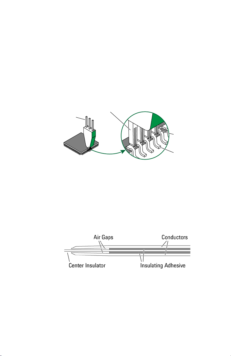
Figure 2 shows the adapter’s wedge segments properly inserted
between the IC pins. Two conductors in each wedge segment
make contact with the adjacent IC pins. The conductors are
connected to the adapter’s output pins. The adapters are
designed for an IC pin spacing of either 0.5 mm or 0.65 mm.
Adapters with 0.5 mm spacing are marked with orange and
adapters with 0.65 mm spacing are marked with green.
Figure 2 Adapter Conductors Inserted Between IC Pins
Critical Connection Information
Figure 3 shows that wedge segments consists of two separate
conductors insulated from each other by a center insulator. A
shortened insulating adhesive between the center insulator and
the outer conductors creates an air gap at the tip of the wedge
segment. The air gap allows the conductors to conform as the
adapter is inserted between the IC pins.
Figure 3 Cross-Section View of Wedge Segment
The 3-signal adapter has 4 wedge segments that form 3 gaps. The
8-signal adapter has 9 wedge segments and 8 gaps. The
16-signal adapter has 17 wedge segments and 16 gaps.
8
Page 9
Critical Connection Information
CAUTION
CAUTION
CAUTION
CAUTION
NOTE
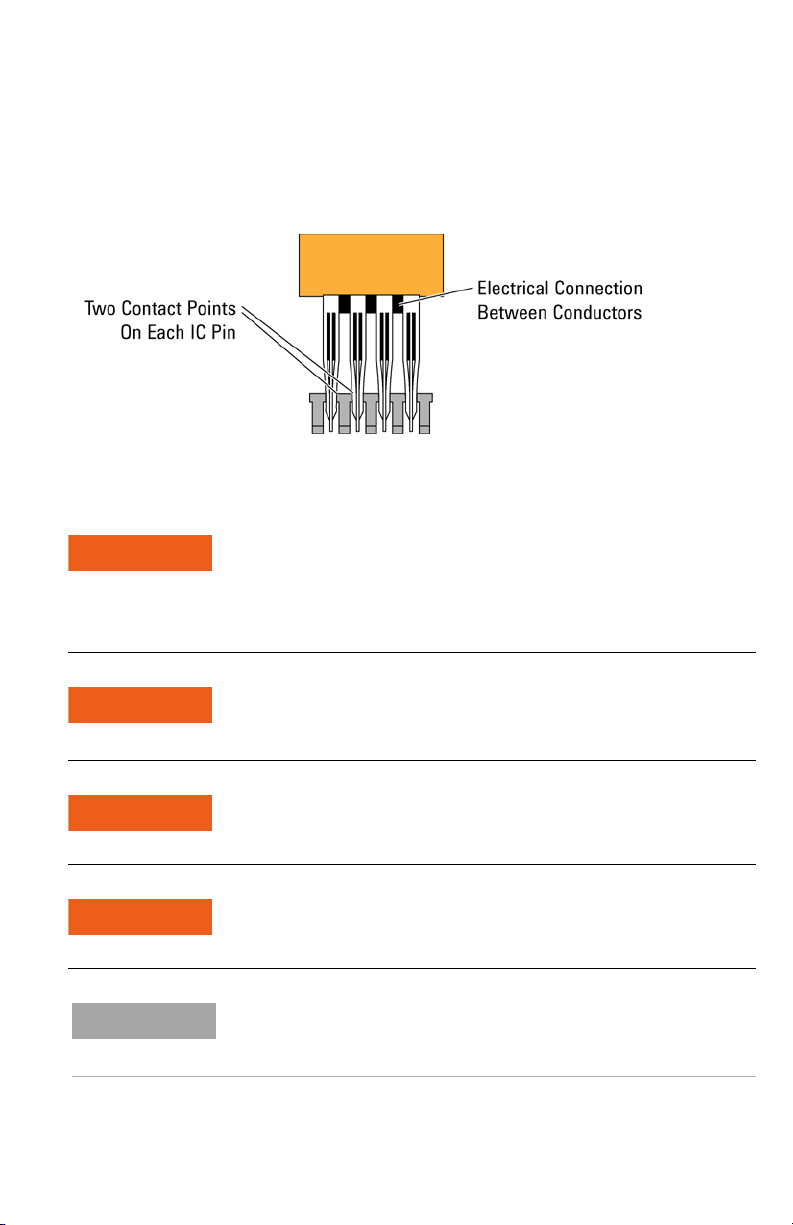
The wedge segment’s conductors provide two contact points on
each IC pin under test as shown on Figure 4. The redundant
physical connection between the wedge segments and the pins
on the IC package increases reliability of the electrical connection.
Figure 4 Two Conductors on Each IC Pin
The wedge probe adapter is a precision tool designed for probing at a
specific IC pin gap spacing. Although to the naked eye it’s difficult to see
the difference between an IC having 0.5 mm or 0.65 mm pin spacing gaps.
While it has been tested for 30,000 insertions, damage to the wedge probe
adapter can easily occur if not used with care.
Always use the magnifying glass provided to ensure the conductors of the
wedge probe adapter are accurately aligned with the dam bar gaps before
applying pressure to insert.
Ensure that you use the correct size wedge probe adapter for the part you
are probing.
If damage occurs to the wedge probe adapter, refer to “Repairing an
Adapter" on page 19.
There can be a significant variation in the pin spacing of 0.65 mm ICs. While
the 0.65 mm wedge probe adapter will work with the vast majority of
0.65 mm ICs, we can not guarantee it’s performance for all ICs.
9
Page 10

Critical Connection Information
Differences in Supported Surface-Mounted Devices
The manufacturing process for making TQFP/PQFPs uses a dam
bar, which prevents the plastic from spewing out between the pins
of the part during the molding process.
After the plastic injection process is completed, the residual metal
dam bar is removed to allow electrical isolation of each pin,
accomplished by a precision blanking die. The resulting gap
between the pins of the part is commonly referred to as the dam
bar gap. The dam bar gap is critical for this type of probing
because the wedge segments actually make electrical contact
with the pins of the TQFP/PQFP package in this area.
When probing, always check the width of the dam bar gap to
make sure it is free of excess solder. See Figure 5 on page 11.
Wicking of solder up the pin and into the dam bar region reduces
the dam bar gap width, which can prevent insertion of the wedge
probe adapter.
Confirm that the pin spacing gap, identified in Figure 5, is 0.5 mm
or 0.65 mm to ensure that the adapter will fit properly. Figure 6 on
page 12 show the supported surface-mounted integrated circuits
and dimensions for specific ICs.
10
Page 11

Critical Connection Information
Figure 5 Dam Bar Gaps and Pin Spacing
11
Page 12

Critical Connection Information
Figure 6 Supported Surface-Mounted Integrated Circuits
12
Page 13
Connecting the Adapter to an IC
CAUTION
CAUTION
To avoid damaging the adapter, study “Critical Connection Information" on
page 8 before attempting to install the adapter on an IC.
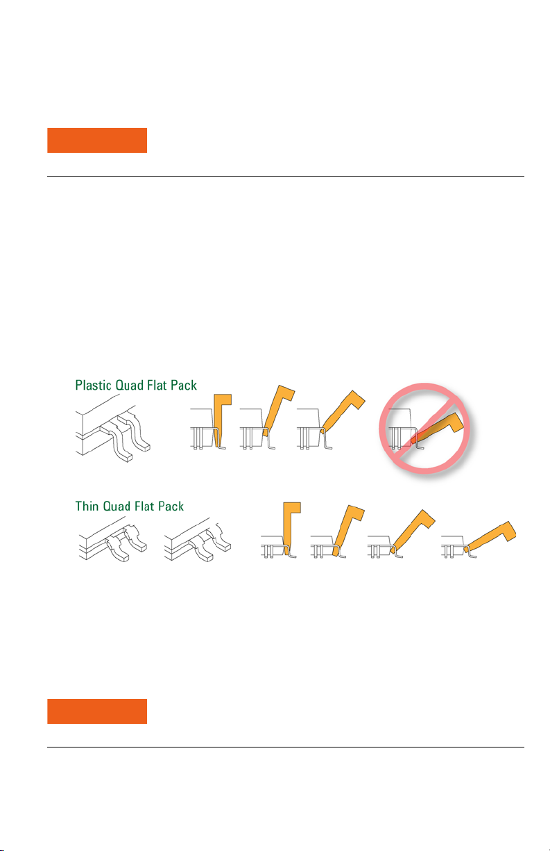
Figure 7 shows various techniques for inserting the adapter,
depending on the thickness of the IC and the location of the dam
bar gap. For most PQFP packages, the dam bar gap portion of the
IC pin is horizontal to and adjacent to the plastic body of the
package, requiring insertion of the wedge probe adapter at a 90°
angle, as shown in the top portion of the figure.
For thinner packages, such as the TQFP type, the dam bar gap
portion of the IC pin is often located on the bend of the pin,
requiring insertion of the wedge probe adapter at a lesser angle
than 90°, as shown in the bottom portion of the figure.
Connecting the Adapter to an IC
Figure 7 Adapter Insertion Techniques
Once the adapter is properly located between the IC pins and in
the dam bar gap, apply pressure so the adapter becomes fully
seated.
Ensure that the adapter is inserted at the proper angle to make contact in
the dam bar gap area.
13
Page 14

Connecting the Adapter to an IC
After the adapter is attached, it should have a very solid
connection to the IC. You should be able to attach a lead to the
adapter while maintaining a good connection to the IC. If the
adapter becomes loose after you attach it, check for one of the
following problems:
- the adapter has not been inserted far enough onto the pins of
the IC as shown in the Figure 7. Try inserting the at a different
angle, perhaps an angle of less than 30° to the board.
- the adapter has not been inserted in the dam bar gap portion
of the IC pins. The dam bar gap is located at the thicker part of
the IC pin and is generally closer to the body of the IC. Try
inserting the adapter on the portion of the IC pins closer to the
body of the IC.
- the IC may be a ceramic package which has no dam bar gap.
The adapters are not designed for this type of IC package.
Common Ground Plane on 16-Pin Adapters
Figure 8 on page 15 shows the pin number assignments for each
probe.
The top side of the 16-pin wedge probe adapters have pins
numbered 1 through 16 and provides access to IC signals. The 16
pins (marked GROUND) on the bottom side of the adapter are
connected together to provide a common ground plane. If any of
the signals acquired in the 16-signal segment from the IC are
connected to ground, a removable jumper (3 provided) can be
used to tie this IC ground signal to the ground plane connected to
the bottom 16 pins on the wedge connector. After this connection
is made, all 16 bottom pins are connected to ground.
14
Page 15

Connecting the Adapter to an IC
Figure 8 Adapters Pins
15
Page 16

Connecting the Adapter to an Instrument
Connecting the Adapter to an Instrument
Keysight Oscilloscopes and Logic Analyzers
The adapter can be easily attached to Keysight oscilloscopes or
logic analyzers. For Keysight oscilloscope probes, use a dual lead
adapter as shown below.
Figure 9 Adapters Connected Using a Dual-Lead Adapter
Tab le 3 Dual-Lead Adapters for Keysight Oscilloscope Probe Families
Keysight
Probe Family Dual lead Adapter Part Number Image
N2870A series 0960-2898 (sold separately or
with N2877A/N2879A accessory
kits)
10070 series 8710-2063
10400A series 5081-7742
16
Page 17

Other Instruments
To maintain a solid connection to the wedge probe adapter, you
will need to use a flexible lead between the probe and the wedge
probe adapter pins. Without the flexible lead, the weight of the
probe on the wedge probe adapter will most likely cause the
wedge probe adapter to disconnect from the IC.
The adapter pins are 0.635 mm square. You can build your own
flexible lead as shown in Figure 10. This requires a socket
designed to fit a 0.380 to 0.635 mm square pin at the end of the
wire that will be connected to the wedge probe adapter. You will
need to define the size of the socket at the probe end of the wire.
The probe for your instrument may include flexible leads. Also, one
of the Keysight dual-lead adapters may fit your instrument’s
probe.
Connecting the Adapter to an Instrument
Figure 10 Build Your Own Flexible Lead
17
Page 18

Cleaning an Adapter
Clean the adapter contacts before each installation. Debris on the
contacts will interfere with its function.
1 Use a common toothbrush to remove any dust between the
wedge segments. The individual wedge segments are very robust
and will not be damaged by vigorous brushing.
Figure 11 Brush in The Direction Shown
2 Use precision dusting cleaner (also known as inert dusting gas or
compressed air in a can) to remove debris loosened by the
brushing.
Cleaning an Adapter
18
Page 19

Repairing an Adapter
WARNING
Typical Bent Wedge Segments
To avoid possible injury, exercise care when using any sharp tool.
1 Use a single-edged razor blade between the wedge probe adapter
conductors to straighten them as much as possible.
2 Repeat this on each bent wedge segment conductor.
Repairing an Adapter
Figure 12 Straightening Wedge Segments
3 Hold the Wedge Probes Adapter conductors tightly together with
tweezers and flex to straighten each individual wedge segment as
shown in Figure 13 on page 20.
19
Page 20

Figure 13 Holding the Wedge Probes Adapter Conductors
NOTE
Severely Bent Wedge Segments
1 Use a x20 or x40 microscope so you can see the bent wedge
segment conductor.
2 Use a needle probe to bend the wedge segment conductor
enough that you can get tweezers on it.
3 Gently straighten out wedge segment conductors using tweezers
as shown in Figure 14 on page 21.
Repairing an Adapter
Even though the bent section often breaks due to metal fatigue, an
electrical connection is often made because there are two electrical contact
points on each pin of the TQFP/PQFP package. For more information on how
electrical connection is made, refer to “Critical Connection Information" on
page 8.
20
Page 21

Figure 14 Straightening Wedge Segment Conductors
WARNING
Pinched Air Gap
The air gap is described in “Critical Connection Information" on
page 8. Wedge segments may fail to make contact if this air gap is
closed. The following instructions tell you how to correct this
problem.
1 Turn the probe so that the wedge segments are facing up.
2 Use a x20 or x40 microscope so you can see the pinched wedge
segment.
Repairing an Adapter
To avoid possible injury, exercise care when using any sharp tool.
3 Insert the edge of a single-edged razor blade between the center
insulator and the conductor.
4 Gently pry the conductor away from the center insulator to open
the gap.
21
Page 22
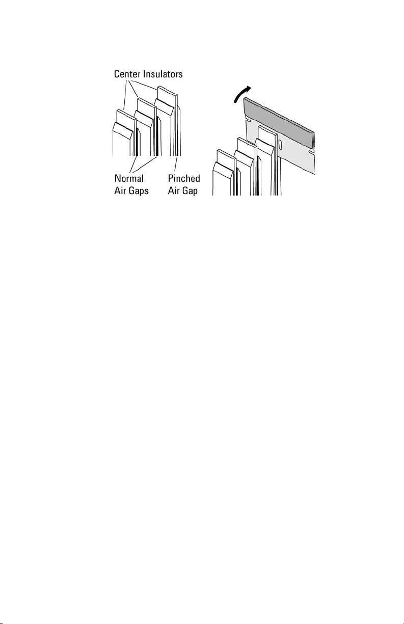
Figure 15 Repairing a Pinched Air Gap
Repairing an Adapter
22
Page 23

Repairing an Adapter
23
Page 24

*E2613-92010*
Keysight Technologies, Inc.
Manual Part Number: E2613-92010
 Loading...