

Page 1

75000 Series C
User Manual and SCPI Programming
Keysight E1406A Command Module
Page 2

Page 3

Notices
© Keysight Technologies, Inc. 1996-2019
No part of this manual may be reproduced in any form or by any means
(including electronic storage and retrieval
or translation into a foreign language)
without prior agreement and written consent from Keysight Technologies, Inc. as
governed by United States and international copyright laws.
Manual Part Number
E1406-90004
Edition
Fifth Edition, August 2019
Published by
Keysight Technologies, Inc.
900 S. Taft Ave.
Loveland, CO 80537 USA
Sales and Technical Support
To contact Keysight for sales and technical support, refer to the support links on
the following Keysight websites:
www.keysight.com/find/E1406A
(product-specific information and support, software and documentation
updates)
www.keysight.com/find/assist (world-
wide contact information for repair and
service)
Declaration of Conformity
Declarations of Conformity for this product and for other Keysight products may
be downloaded from the Web. Go to
http://keysight.com/go/conformity and
click on “Declarations of Conformity.” You
can then search by product number to
find the latest Declaration of Conformity.
Technology Licenses
The hardware and/or software described
in this document are furnished under a
license and may be used or copied only in
accordance with the terms of such
license.
Warranty
THE MATERIAL CONTAINED IN THIS
DOCUMENT IS PROVIDED “AS IS,” AND
IS SUBJECT TO BEING CHANGED,
WITHOUT NOTICE, IN FUTURE EDITIONS. FURTHER, TO THE MAXIMUM
EXTENT PERMITTED BY APPLICABLE
LAW, KEYSIGHT DISCLAIMS ALL WARRANTIES, EITHER EXPRESS OR IMPLIED,
WITH REGARD TO THIS MANUAL AND
ANY INFORMATION CONTAINED
HEREIN, INCLUDING BUT NOT LIMITED
TO THE IMPLIED WARRANTIES OF MERCHANTABILITY AND FITNESS FOR A
PARTICULAR PURPOSE. KEYSIGHT
SHALL NOT BE LIABLE FOR ERRORS OR
FOR INCIDENTAL OR CONSEQUENTIAL
DAMAGES IN CONNECTION WITH THE
FURNISHING, USE, OR PERFORMANCE
OF THIS DOCUMENT OR OF ANY INFORMATION CONTAINED HEREIN. SHOULD
KEYSIGHT AND THE USER HAVE A SEPARATE WRITTEN AGREEMENT WITH
WARRANTY TERMS COVERING THE
MATERIAL IN THIS DOCUMENT THAT
CONFLICT WITH THESE TERMS, THE
WARRANTY TERMS IN THE SEPARATE
AGREEMENT SHALL CONTROL.
Keysight Technologies does not warrant
third-party system-level (combination of
chassis, controllers, modules, etc.) performance, safety, or regulatory compliance unless specifically stated.
DFARS/Restricted Rights
Notices
If software is for use in the performance
of a U.S. Government prime contract or
subcontract, Software is delivered and
licensed as “Commercial computer software” as defined in DFAR 252.227-7014
(June 1995), or as a “commercial item” as
defined in FAR 2.101(a) or as “Restricted
computer software” as defined in FAR
52.227-19 (June 1987) or any equivalent
agency regulation or contract clause.
Use, duplication or disclosure of Software
is subject to Keysight Technologies’ standard commercial license terms, and nonDOD Departments and Agencies of the
U.S. Government will receive no greater
than Restricted Rights as defined in FAR
52.227-19(c)(1-2) (June 1987). U.S. Government users will receive no greater
than Limited Rights as defined in FAR
52.227-14 (June 1987) or DFAR 252.2277015 (b)(2) (November 1995), as applicable in any technical data.
Page 4

Safety Information
The following general safety precautions must be observed during all
phases of operation of this instrument.
Failure to comply with these precautions or with specific warnings or operating instructions in the product
manuals violates safety standards of
design, manufacture, and intended use
of the instrument. Keysight Technologies assumes no liability for the customer's failure to comply with these
requirements.
General
Do not use this product in any manner not
specified by the manufacturer. The protective features of this product must not be
impaired if it is used in a manner specified in
the operation instructions.
Before Applying Power
Verify that all safety precautions are taken.
Make all connections to the unit before
applying power. Note the external markings
described under “Safety Symbols”.
Ground the Instrument
Keysight chassis’ are provided with a
grounding-type power plug. The
instrument chassis and cover must be
connected to an electrical ground to
minimize shock hazard. The ground pin
must be firmly connected to an electrical ground (safety ground) terminal at
the power outlet. Any interruption of
the protective (grounding) conductor
or disconnection of the protective
earth terminal will cause a potential
shock hazard that could result in personal injury.
Do Not Operate in an Explosive
Atmosphere
Do not operate the module/chassis in
the presence of flammable gases or
fumes.
Do Not Operate Near Flammable
Liquids
Do not operate the module/chassis in
the presence of flammable liquids or
near containers of such liquids.
Cleaning
Clean the outside of the Keysight module/chassis with a soft, lint-free,
slightly dampened cloth. Do not use
detergent or chemical solvents.
Do Not Remove Instrument Cover
Only qualified, service-trained personnel who are aware of the hazards
involved should remove instrument
covers. Always disconnect the power
cable and any external circuits before
removing the instrument cover.
Keep away from live circuits
Operating personnel must not remove
equipment covers or shields. Procedures involving the removal of covers
and shields are for use by servicetrained personnel only. Under certain
conditions, dangerous voltages may
exist even with the equipment
switched off. To avoid dangerous electrical shock, DO NOT perform procedures involving cover or shield removal
unless you are qualified to do so.
DO NOT operate damaged
equipment
Whenever it is possible that the safety
protection features built into this product have been impaired, either through
physical damage, excessive moisture,
or any other reason, REMOVE POWER
and do not use the product until safe
operation can be verified by servicetrained personnel. If necessary, return
the product to a Keysight Technologies
Sales and Service Office for service and
repair to ensure the safety features are
maintained.
DO NOT block the primary
disconnect
The primary disconnect device is the
appliance connector/power cord when
a chassis used by itself, but when
installed into a rack or system the disconnect may be impaired and must be
considered part of the installation.
Do Not Modify the Instrument
Do not install substitute parts or perform any unauthorized modification to
the product. Return the product to a
Keysight Sales and Service Office to
ensure that safety features are maintained.
In Case of Damage
Instruments that appear damaged or
defective should be made inoperative
and secured against unintended operation until they can be repaired by
qualified service personnel
Do NOT block vents and fan exhaust:
To ensure adequate cooling and ventilation, leave a gap of at least 50mm
(2") around vent holes on both sides of
the chassis.
Do NOT operate with empty slots: To
ensure proper cooling and avoid damaging equipment, fill each empty slot
with an AXIe filler panel module.
Do NOT stack free-standing chassis:
Stacked chassis should be rackmounted.
All modules are grounded through the
chassis: During installation, tighten
each module's retaining screws to
secure the module to the chassis and
to make the ground connection.
Operator is responsible to maintain
safe operating conditions. To ensure
safe operating conditions, modules
should not be operated beyond the full
temperature range specified in the
Environmental and physical specification. Exceeding safe operating conditions can result in shorter lifespan,
improper module performance and
user safety issues. When the modules
are in use and operation within the
specified full temperature range is not
maintained, module surface temperatures may exceed safe handling conditions which can cause discomfort or
burns if touched. In the event of a
module exceeding the full temperature
range, always allow the module to cool
before touching or removing modules
from the chassis.
iv
Page 5

Safety Symbols
A CAUTION denotes a hazard. It
calls attention to an operating procedure or practice, that, if not correctly performed or adhered to
could result in damage to the
product or loss of important data.
Do not proceed beyond a CAUTION
notice until the indicated conditions are fully understood and met.
A WARNING denotes a hazard. It
calls attention to an operating procedure or practice, that, if not correctly performed or adhered to,
could result in personal injury or
death. Do not proceed beyond a
WARNING notice until the indicated conditions are fully understood and met.
Products display the following symbols:
Warning, risk of electric
shock
Refer to manual for additional safety information.
Earth Ground.
Chassis Ground.
Alternating Current (AC).
Direct Current (DC)
v
Page 6

vi
Page 7

Contents
1 Keysight E1406A Command Module Overview
About This Chapter . . . . . . . . . . . . . . . . . . . . . . . . . . . . . . . . . . . . . . . . . . . . . . 25
Warnings and Cautions . . . . . . . . . . . . . . . . . . . . . . . . . . . . . . . . . . . . . . . . . . . 25
Using Keysight VIC. . . . . . . . . . . . . . . . . . . . . . . . . . . . . . . . . . . . . . . . . . . . . . . 26
Command Module Functional Description . . . . . . . . . . . . . . . . . . . . . . . . . . . . 27
Command Module Physical Description . . . . . . . . . . . . . . . . . . . . . . . . . . . . . . 28
Faceplate Annunciators . . . . . . . . . . . . . . . . . . . . . . . . . . . . . . . . . . . . . . . . 28
Faceplate CLK10 and Trigger Connectors . . . . . . . . . . . . . . . . . . . . . . . . . . 29
The GPIB and RS-232 Ports . . . . . . . . . . . . . . . . . . . . . . . . . . . . . . . . . . . . . 29
The Run/Load Switch . . . . . . . . . . . . . . . . . . . . . . . . . . . . . . . . . . . . . . . . . . 29
The Reset Button. . . . . . . . . . . . . . . . . . . . . . . . . . . . . . . . . . . . . . . . . . . . . . 29
Extraction Levers. . . . . . . . . . . . . . . . . . . . . . . . . . . . . . . . . . . . . . . . . . . . . . 29
Installing the Command Module in a Mainframe . . . . . . . . . . . . . . . . . . . . . . . 30
Command Module Memory . . . . . . . . . . . . . . . . . . . . . . . . . . . . . . . . . . . . . . . . 31
Battery Backed Functions. . . . . . . . . . . . . . . . . . . . . . . . . . . . . . . . . . . . . . . 31
2 Configuring the Keysight E1406A Command Module
About This Chapter . . . . . . . . . . . . . . . . . . . . . . . . . . . . . . . . . . . . . . . . . . . . . . 33
System Configuration Sequence . . . . . . . . . . . . . . . . . . . . . . . . . . . . . . . . . . . . 33
Modules Configured Statically and Dynamically. . . . . . . . . . . . . . . . . . . . . . . . 34
Identifying Statically Configured Modules . . . . . . . . . . . . . . . . . . . . . . . . . . 34
Identifying Dynamically Configured Modules. . . . . . . . . . . . . . . . . . . . . . . . 34
User-Defined Dynamic Configuration. . . . . . . . . . . . . . . . . . . . . . . . . . . . . . 35
The Dynamic Configuration Table . . . . . . . . . . . . . . . . . . . . . . . . . . . . . . 35
Table Format . . . . . . . . . . . . . . . . . . . . . . . . . . . . . . . . . . . . . . . . . . . . . . 36
Determining the Table Size. . . . . . . . . . . . . . . . . . . . . . . . . . . . . . . . . . . . . . 36
Data Format . . . . . . . . . . . . . . . . . . . . . . . . . . . . . . . . . . . . . . . . . . . . . . . . . 37
Example: Dynamically Configuring a Module. . . . . . . . . . . . . . . . . . . . . . . . 37
Comments . . . . . . . . . . . . . . . . . . . . . . . . . . . . . . . . . . . . . . . . . . . . . . . . 39
Setting VXI-MXI Configuration . . . . . . . . . . . . . . . . . . . . . . . . . . . . . . . . . . . . . 40
Logical Address Configuration . . . . . . . . . . . . . . . . . . . . . . . . . . . . . . . . . . . 40
Default Logical Address Assignments . . . . . . . . . . . . . . . . . . . . . . . . . . . . . 40
A16/A24/A32 Address Window Configuration. . . . . . . . . . . . . . . . . . . . . . . 41
Default A16/A24/A32 Address Window Assignments . . . . . . . . . . . . . . . . . 42
Interrupt Register Configuration. . . . . . . . . . . . . . . . . . . . . . . . . . . . . . . . . . 43
TTL Trigger Register Configuration. . . . . . . . . . . . . . . . . . . . . . . . . . . . . . . . 43
ECL Trigger Register Configuration . . . . . . . . . . . . . . . . . . . . . . . . . . . . . . . 43
Utility Register Configuration . . . . . . . . . . . . . . . . . . . . . . . . . . . . . . . . . . . . 43
Keysight E1406A User Manual and SCPI Programming Guide vii
Page 8

User-Defined Logical Address and Memory Windows. . . . . . . . . . . . . . . . . 44
The User-Defined Extender Table . . . . . . . . . . . . . . . . . . . . . . . . . . . . . . 44
Table Format . . . . . . . . . . . . . . . . . . . . . . . . . . . . . . . . . . . . . . . . . . . . . . 45
Determining the Table Size . . . . . . . . . . . . . . . . . . . . . . . . . . . . . . . . . . . 47
Data Format . . . . . . . . . . . . . . . . . . . . . . . . . . . . . . . . . . . . . . . . . . . . . . . 47
Example: User-Defined Extender Table . . . . . . . . . . . . . . . . . . . . . . . . . . . . 48
Comments . . . . . . . . . . . . . . . . . . . . . . . . . . . . . . . . . . . . . . . . . . . . . . . . 50
Setting Commander/Servant Hierarchies . . . . . . . . . . . . . . . . . . . . . . . . . . . . . 53
User-Defined Commander/Servant Hierarchies . . . . . . . . . . . . . . . . . . . . . 54
The User-Defined Commander/Servant Hierarchy Table . . . . . . . . . . . . . . 54
Table Format . . . . . . . . . . . . . . . . . . . . . . . . . . . . . . . . . . . . . . . . . . . . . . . . . 55
Determining the Table Size. . . . . . . . . . . . . . . . . . . . . . . . . . . . . . . . . . . . . . 55
Data Format . . . . . . . . . . . . . . . . . . . . . . . . . . . . . . . . . . . . . . . . . . . . . . . . . 56
Example: Assigning a Secondary GPIB Address. . . . . . . . . . . . . . . . . . . . . . 56
Comments . . . . . . . . . . . . . . . . . . . . . . . . . . . . . . . . . . . . . . . . . . . . . . . . 57
A24/A32 Address Mapping . . . . . . . . . . . . . . . . . . . . . . . . . . . . . . . . . . . . . . . . 59
A24/A32 Address Allocation . . . . . . . . . . . . . . . . . . . . . . . . . . . . . . . . . . . . . 59
Allocating Address Space for VMEbus Devices . . . . . . . . . . . . . . . . . . . . . . 60
Allocating Address Space for VMEbus Devices: Method 1. . . . . . . . . . . 60
Reserving A24/A32 Address Space . . . . . . . . . . . . . . . . . . . . . . . . . . . . . . . 64
The A24/A32 Address Allocation Table. . . . . . . . . . . . . . . . . . . . . . . . . . 64
Table Format . . . . . . . . . . . . . . . . . . . . . . . . . . . . . . . . . . . . . . . . . . . . . . 64
Determining the Table Size . . . . . . . . . . . . . . . . . . . . . . . . . . . . . . . . . . . 65
Data Format . . . . . . . . . . . . . . . . . . . . . . . . . . . . . . . . . . . . . . . . . . . . . . . 66
The Table Header. . . . . . . . . . . . . . . . . . . . . . . . . . . . . . . . . . . . . . . . . . . 66
Example: Reserving A24 Addresses for a VMEbus Device . . . . . . . . . . . 66
Comments . . . . . . . . . . . . . . . . . . . . . . . . . . . . . . . . . . . . . . . . . . . . . . . . 67
ERROR 8: INACCESSIBLE A24 MEMORY . . . . . . . . . . . . . . . . . . . . . . . . 68
ERROR 32: INACCESSIBLE A32 MEMORY . . . . . . . . . . . . . . . . . . . . . . . 68
ERROR 33: INVALID UDEF MEMORY BLOCK . . . . . . . . . . . . . . . . . . . . . 68
ERROR 34: UDEF MEMORY BLOCK UNAVAILABLE . . . . . . . . . . . . . . . . 68
ERROR 35: INVALID UDEF ADDRESS SPACE. . . . . . . . . . . . . . . . . . . . . 68
ERROR 36: DUPLICATE UDEF MEMORY LADD . . . . . . . . . . . . . . . . . . . 68
ERROR 43: INVALID UDEF MEM TABLE . . . . . . . . . . . . . . . . . . . . . . . . . 68
ERROR 44: INVALID UDEF MEM TABLE DATA . . . . . . . . . . . . . . . . . . . . 68
Interrupt Line Allocation . . . . . . . . . . . . . . . . . . . . . . . . . . . . . . . . . . . . . . . . . . 69
User-Defined Interrupt Line Allocation Table . . . . . . . . . . . . . . . . . . . . . 70
The Interrupt Line Allocation Table . . . . . . . . . . . . . . . . . . . . . . . . . . . . . 70
Table Format . . . . . . . . . . . . . . . . . . . . . . . . . . . . . . . . . . . . . . . . . . . . . . 71
Determining the Table Size . . . . . . . . . . . . . . . . . . . . . . . . . . . . . . . . . . . 72
Data Format . . . . . . . . . . . . . . . . . . . . . . . . . . . . . . . . . . . . . . . . . . . . . . . 73
Example: Assigning an Interrupt Line . . . . . . . . . . . . . . . . . . . . . . . . . . . 73
Comments . . . . . . . . . . . . . . . . . . . . . . . . . . . . . . . . . . . . . . . . . . . . . . . . 75
ERROR 24: INTERRUPT LINE UNAVAILABLE . . . . . . . . . . . . . . . . . . . . . 76
ERROR 25: INVALID UDEF HANDLER. . . . . . . . . . . . . . . . . . . . . . . . . . . 76
ERROR 26: INVALID UDEF INTERRUPTER . . . . . . . . . . . . . . . . . . . . . . . 76
ERROR 41: INVALID UDEF INTR TABLE . . . . . . . . . . . . . . . . . . . . . . . . . 76
viii Keysight E1406A User Manual and SCPI Programming Guide
Page 9

ERROR 42: INVALID UDEF INTR TABLE DATA . . . . . . . . . . . . . . . . . . . . 76
Starting System Operation . . . . . . . . . . . . . . . . . . . . . . . . . . . . . . . . . . . . . . . . 77
VXI SYSFAIL* Line . . . . . . . . . . . . . . . . . . . . . . . . . . . . . . . . . . . . . . . . . . . . . . . 77
3 Using the Display Terminal Interface
About This Chapter . . . . . . . . . . . . . . . . . . . . . . . . . . . . . . . . . . . . . . . . . . . . . . 79
Terminal Interface Features . . . . . . . . . . . . . . . . . . . . . . . . . . . . . . . . . . . . . . . . 80
Using Display Terminal Menus . . . . . . . . . . . . . . . . . . . . . . . . . . . . . . . . . . . . . 80
How Instruments Appear in the Menu. . . . . . . . . . . . . . . . . . . . . . . . . . . . . 81
Multiple Command Modules . . . . . . . . . . . . . . . . . . . . . . . . . . . . . . . . . . 81
Display Terminal Menu Tutorial . . . . . . . . . . . . . . . . . . . . . . . . . . . . . . . . . . 82
Using the System Instrument Menu . . . . . . . . . . . . . . . . . . . . . . . . . . . . . . 84
Using the Loader Instrument . . . . . . . . . . . . . . . . . . . . . . . . . . . . . . . . . . . . 90
Using the Switchbox Menu . . . . . . . . . . . . . . . . . . . . . . . . . . . . . . . . . . . 90
Selecting the Switchbox . . . . . . . . . . . . . . . . . . . . . . . . . . . . . . . . . . . . . 90
Monitor Mode . . . . . . . . . . . . . . . . . . . . . . . . . . . . . . . . . . . . . . . . . . . . . . . . 94
Reading Error Messages . . . . . . . . . . . . . . . . . . . . . . . . . . . . . . . . . . . . . 95
Executing Commands . . . . . . . . . . . . . . . . . . . . . . . . . . . . . . . . . . . . . . . . . . . . 96
Editing the Terminal Display. . . . . . . . . . . . . . . . . . . . . . . . . . . . . . . . . . . . . 96
General Key Descriptions . . . . . . . . . . . . . . . . . . . . . . . . . . . . . . . . . . . . . . . . . 97
Menu and Menu Control Keys . . . . . . . . . . . . . . . . . . . . . . . . . . . . . . . . . . . 97
Instrument Control Keys. . . . . . . . . . . . . . . . . . . . . . . . . . . . . . . . . . . . . . . . 98
Editing Keys . . . . . . . . . . . . . . . . . . . . . . . . . . . . . . . . . . . . . . . . . . . . . . . . . 98
Other Keys . . . . . . . . . . . . . . . . . . . . . . . . . . . . . . . . . . . . . . . . . . . . . . . . . . 98
Using Supported Terminals. . . . . . . . . . . . . . . . . . . . . . . . . . . . . . . . . . . . . . . . 99
The Supported Terminals . . . . . . . . . . . . . . . . . . . . . . . . . . . . . . . . . . . . . . . 99
Using the HP 700/22 . . . . . . . . . . . . . . . . . . . . . . . . . . . . . . . . . . . . . . . . . . 99
VT100 Key Map . . . . . . . . . . . . . . . . . . . . . . . . . . . . . . . . . . . . . . . . . . . 100
Selecting VT100 Mode . . . . . . . . . . . . . . . . . . . . . . . . . . . . . . . . . . . . . 100
VT220 Key Map . . . . . . . . . . . . . . . . . . . . . . . . . . . . . . . . . . . . . . . . . . . 100
Selecting VT220 Mode . . . . . . . . . . . . . . . . . . . . . . . . . . . . . . . . . . . . . 101
Using the WYSE WY-30 . . . . . . . . . . . . . . . . . . . . . . . . . . . . . . . . . . . . . . . 102
Using Other Terminals . . . . . . . . . . . . . . . . . . . . . . . . . . . . . . . . . . . . . . . . . . . 103
What “Not Supported” Means . . . . . . . . . . . . . . . . . . . . . . . . . . . . . . . . . . 103
Testing Terminals for Compatibility . . . . . . . . . . . . . . . . . . . . . . . . . . . . . . 103
Using a Terminal Without Menus. . . . . . . . . . . . . . . . . . . . . . . . . . . . . . . . 104
Selecting Instruments . . . . . . . . . . . . . . . . . . . . . . . . . . . . . . . . . . . . . . 104
SI Command . . . . . . . . . . . . . . . . . . . . . . . . . . . . . . . . . . . . . . . . . . . . . 105
SA Command. . . . . . . . . . . . . . . . . . . . . . . . . . . . . . . . . . . . . . . . . . . . . 105
Returning to the “Select an Instrument” Prompt . . . . . . . . . . . . . . . . . 105
Keysight E1406A User Manual and SCPI Programming Guide ix
Page 10

Control Sequences for Terminal Interface Functions . . . . . . . . . . . . . . . . . 106
In Case of Difficulty . . . . . . . . . . . . . . . . . . . . . . . . . . . . . . . . . . . . . . . . . . . . . 107
System Instrument/Switchbox Menus. . . . . . . . . . . . . . . . . . . . . . . . . . . . . . . 108
4 Triggering and System Status
About This Chapter . . . . . . . . . . . . . . . . . . . . . . . . . . . . . . . . . . . . . . . . . . . . . 123
Using VXI Backplane Trigger Lines and Ports . . . . . . . . . . . . . . . . . . . . . . . . . 123
Programming the Trigger Lines and the Trigger Ports. . . . . . . . . . . . . . . . 124
Enabling Trigger Lines and the Trig Out Port . . . . . . . . . . . . . . . . . . . . . . . 125
Setting the Trigger Source . . . . . . . . . . . . . . . . . . . . . . . . . . . . . . . . . . . . . 125
Setting the Trigger Level. . . . . . . . . . . . . . . . . . . . . . . . . . . . . . . . . . . . . . . 125
Sending a Trigger Pulse . . . . . . . . . . . . . . . . . . . . . . . . . . . . . . . . . . . . . . . 126
Querying the Trigger State, Source, and Level. . . . . . . . . . . . . . . . . . . . . . 126
Programming the Status System. . . . . . . . . . . . . . . . . . . . . . . . . . . . . . . . . . . 127
General Status Register Model. . . . . . . . . . . . . . . . . . . . . . . . . . . . . . . . . . 127
Condition Register . . . . . . . . . . . . . . . . . . . . . . . . . . . . . . . . . . . . . . . . . 128
Transition Filter . . . . . . . . . . . . . . . . . . . . . . . . . . . . . . . . . . . . . . . . . . . 128
Event Register . . . . . . . . . . . . . . . . . . . . . . . . . . . . . . . . . . . . . . . . . . . . 128
Enable Register . . . . . . . . . . . . . . . . . . . . . . . . . . . . . . . . . . . . . . . . . . . 128
An Example Sequence . . . . . . . . . . . . . . . . . . . . . . . . . . . . . . . . . . . . . . 128
Required Status Groups . . . . . . . . . . . . . . . . . . . . . . . . . . . . . . . . . . . . . . . 129
Status Byte Group . . . . . . . . . . . . . . . . . . . . . . . . . . . . . . . . . . . . . . . . . 131
Standard Event Status Group . . . . . . . . . . . . . . . . . . . . . . . . . . . . . . . . . . . 132
Standard Operation Status Group . . . . . . . . . . . . . . . . . . . . . . . . . . . . . . . 133
Questionable Data Group . . . . . . . . . . . . . . . . . . . . . . . . . . . . . . . . . . . . . . 134
Status System Programming Examples . . . . . . . . . . . . . . . . . . . . . . . . . . . . . 136
Handling SRQs . . . . . . . . . . . . . . . . . . . . . . . . . . . . . . . . . . . . . . . . . . . . . . 136
Using Message Available (MAV) Bits . . . . . . . . . . . . . . . . . . . . . . . . . . . . . 136
Example Program. . . . . . . . . . . . . . . . . . . . . . . . . . . . . . . . . . . . . . . . . . 137
Using a Service Request (SRQ). . . . . . . . . . . . . . . . . . . . . . . . . . . . . . . . . . 139
Example Program. . . . . . . . . . . . . . . . . . . . . . . . . . . . . . . . . . . . . . . . . . 140
5 Keysight E1406A Command Reference
About This Chapter . . . . . . . . . . . . . . . . . . . . . . . . . . . . . . . . . . . . . . . . . . . . . 143
Command Types. . . . . . . . . . . . . . . . . . . . . . . . . . . . . . . . . . . . . . . . . . . . . . . . 143
Common Command Format . . . . . . . . . . . . . . . . . . . . . . . . . . . . . . . . . . . . 143
SCPI Command Format . . . . . . . . . . . . . . . . . . . . . . . . . . . . . . . . . . . . . . . 144
Command Separator. . . . . . . . . . . . . . . . . . . . . . . . . . . . . . . . . . . . . . . . . . 144
Abbreviated Commands . . . . . . . . . . . . . . . . . . . . . . . . . . . . . . . . . . . . . . . 144
Implied Commands . . . . . . . . . . . . . . . . . . . . . . . . . . . . . . . . . . . . . . . . . . . 145
Variable Command Syntax . . . . . . . . . . . . . . . . . . . . . . . . . . . . . . . . . . . . . 145
Parameter Types . . . . . . . . . . . . . . . . . . . . . . . . . . . . . . . . . . . . . . . . . . . . . 145
x Keysight E1406A User Manual and SCPI Programming Guide
Page 11

Linking Commands. . . . . . . . . . . . . . . . . . . . . . . . . . . . . . . . . . . . . . . . . . . 147
SCPI Command Reference . . . . . . . . . . . . . . . . . . . . . . . . . . . . . . . . . . . . . . . 147
DIAGnostic Subsystem . . . . . . . . . . . . . . . . . . . . . . . . . . . . . . . . . . . . . . . . . . 148
Subsystem Syntax . . . . . . . . . . . . . . . . . . . . . . . . . . . . . . . . . . . . . . . . . . . 148
:BOOT:COLD . . . . . . . . . . . . . . . . . . . . . . . . . . . . . . . . . . . . . . . . . . . . . . . . 149
Comments . . . . . . . . . . . . . . . . . . . . . . . . . . . . . . . . . . . . . . . . . . . . . . . 150
Example . . . . . . . . . . . . . . . . . . . . . . . . . . . . . . . . . . . . . . . . . . . . . . . . . 150
:BOOT[:WARM] . . . . . . . . . . . . . . . . . . . . . . . . . . . . . . . . . . . . . . . . . . . . . . 150
Comments . . . . . . . . . . . . . . . . . . . . . . . . . . . . . . . . . . . . . . . . . . . . . . . 150
Example . . . . . . . . . . . . . . . . . . . . . . . . . . . . . . . . . . . . . . . . . . . . . . . . . 150
:COMMunicate :SERial[0][:OWNer] . . . . . . . . . . . . . . . . . . . . . . . . . . . . . . 151
Parameters. . . . . . . . . . . . . . . . . . . . . . . . . . . . . . . . . . . . . . . . . . . . . . . 151
Comments . . . . . . . . . . . . . . . . . . . . . . . . . . . . . . . . . . . . . . . . . . . . . . . 151
Example . . . . . . . . . . . . . . . . . . . . . . . . . . . . . . . . . . . . . . . . . . . . . . . . . 151
:COMMunicate :SERial[0][:OWNer]? . . . . . . . . . . . . . . . . . . . . . . . . . . . . . 152
Comments . . . . . . . . . . . . . . . . . . . . . . . . . . . . . . . . . . . . . . . . . . . . . . . 152
Example . . . . . . . . . . . . . . . . . . . . . . . . . . . . . . . . . . . . . . . . . . . . . . . . . 152
:COMMunicate :SERial[n]:STORe . . . . . . . . . . . . . . . . . . . . . . . . . . . . . . . . 152
Comments . . . . . . . . . . . . . . . . . . . . . . . . . . . . . . . . . . . . . . . . . . . . . . . 152
Example . . . . . . . . . . . . . . . . . . . . . . . . . . . . . . . . . . . . . . . . . . . . . . . . . 152
:DOWNload:CHECked[:MADDress] . . . . . . . . . . . . . . . . . . . . . . . . . . . . . . 153
Parameters. . . . . . . . . . . . . . . . . . . . . . . . . . . . . . . . . . . . . . . . . . . . . . . 153
Comments . . . . . . . . . . . . . . . . . . . . . . . . . . . . . . . . . . . . . . . . . . . . . . . 153
Byte Format . . . . . . . . . . . . . . . . . . . . . . . . . . . . . . . . . . . . . . . . . . . . . . 154
:DOWNload:CHECked:SADDress . . . . . . . . . . . . . . . . . . . . . . . . . . . . . . . . 155
Parameters. . . . . . . . . . . . . . . . . . . . . . . . . . . . . . . . . . . . . . . . . . . . . . . 155
Comments . . . . . . . . . . . . . . . . . . . . . . . . . . . . . . . . . . . . . . . . . . . . . . . 155
Byte Format . . . . . . . . . . . . . . . . . . . . . . . . . . . . . . . . . . . . . . . . . . . . . . 156
:DOWNload[:MADDress] . . . . . . . . . . . . . . . . . . . . . . . . . . . . . . . . . . . . . . 158
Parameters. . . . . . . . . . . . . . . . . . . . . . . . . . . . . . . . . . . . . . . . . . . . . . . 158
Comments . . . . . . . . . . . . . . . . . . . . . . . . . . . . . . . . . . . . . . . . . . . . . . . 158
Example . . . . . . . . . . . . . . . . . . . . . . . . . . . . . . . . . . . . . . . . . . . . . . . . . 159
:DOWNload:SADDress . . . . . . . . . . . . . . . . . . . . . . . . . . . . . . . . . . . . . . . . 159
Parameters. . . . . . . . . . . . . . . . . . . . . . . . . . . . . . . . . . . . . . . . . . . . . . . 159
Comments . . . . . . . . . . . . . . . . . . . . . . . . . . . . . . . . . . . . . . . . . . . . . . . 159
Example . . . . . . . . . . . . . . . . . . . . . . . . . . . . . . . . . . . . . . . . . . . . . . . . . 160
:DRAM:AVAilable?. . . . . . . . . . . . . . . . . . . . . . . . . . . . . . . . . . . . . . . . . . . . 161
Comments . . . . . . . . . . . . . . . . . . . . . . . . . . . . . . . . . . . . . . . . . . . . . . . 161
Example . . . . . . . . . . . . . . . . . . . . . . . . . . . . . . . . . . . . . . . . . . . . . . . . . 161
:DRAM:CREate . . . . . . . . . . . . . . . . . . . . . . . . . . . . . . . . . . . . . . . . . . . . . . 161
Parameters. . . . . . . . . . . . . . . . . . . . . . . . . . . . . . . . . . . . . . . . . . . . . . . 161
Comments . . . . . . . . . . . . . . . . . . . . . . . . . . . . . . . . . . . . . . . . . . . . . . . 161
Example . . . . . . . . . . . . . . . . . . . . . . . . . . . . . . . . . . . . . . . . . . . . . . . . . 162
:DRAM:CREate? . . . . . . . . . . . . . . . . . . . . . . . . . . . . . . . . . . . . . . . . . . . . . 162
Comments . . . . . . . . . . . . . . . . . . . . . . . . . . . . . . . . . . . . . . . . . . . . . . . 162
:DRIVer:INSTall . . . . . . . . . . . . . . . . . . . . . . . . . . . . . . . . . . . . . . . . . . . . . . 162
Comments . . . . . . . . . . . . . . . . . . . . . . . . . . . . . . . . . . . . . . . . . . . . . . . 162
:DRIVer:LIST[:type]? . . . . . . . . . . . . . . . . . . . . . . . . . . . . . . . . . . . . . . . . . . 163
Parameters. . . . . . . . . . . . . . . . . . . . . . . . . . . . . . . . . . . . . . . . . . . . . . . 163
Keysight E1406A User Manual and SCPI Programming Guide xi
Page 12

Comments . . . . . . . . . . . . . . . . . . . . . . . . . . . . . . . . . . . . . . . . . . . . . . . . . . 163
Example . . . . . . . . . . . . . . . . . . . . . . . . . . . . . . . . . . . . . . . . . . . . . . . . . 163
Example . . . . . . . . . . . . . . . . . . . . . . . . . . . . . . . . . . . . . . . . . . . . . . . . . 164
:DRIVer:LOAD . . . . . . . . . . . . . . . . . . . . . . . . . . . . . . . . . . . . . . . . . . . . . . . 164
Parameters . . . . . . . . . . . . . . . . . . . . . . . . . . . . . . . . . . . . . . . . . . . . . . . 164
Comments . . . . . . . . . . . . . . . . . . . . . . . . . . . . . . . . . . . . . . . . . . . . . . . 164
Example . . . . . . . . . . . . . . . . . . . . . . . . . . . . . . . . . . . . . . . . . . . . . . . . . 164
:DRIVer:LOAD :CHECked. . . . . . . . . . . . . . . . . . . . . . . . . . . . . . . . . . . . . . . 164
Parameters . . . . . . . . . . . . . . . . . . . . . . . . . . . . . . . . . . . . . . . . . . . . . . . 164
Comments . . . . . . . . . . . . . . . . . . . . . . . . . . . . . . . . . . . . . . . . . . . . . . . 165
Example . . . . . . . . . . . . . . . . . . . . . . . . . . . . . . . . . . . . . . . . . . . . . . . . . 165
:FROM:AVAilable? . . . . . . . . . . . . . . . . . . . . . . . . . . . . . . . . . . . . . . . . . . . . 165
Comments . . . . . . . . . . . . . . . . . . . . . . . . . . . . . . . . . . . . . . . . . . . . . . . 165
Example . . . . . . . . . . . . . . . . . . . . . . . . . . . . . . . . . . . . . . . . . . . . . . . . . 165
:FROM:CREate. . . . . . . . . . . . . . . . . . . . . . . . . . . . . . . . . . . . . . . . . . . . . . . 166
Parameters . . . . . . . . . . . . . . . . . . . . . . . . . . . . . . . . . . . . . . . . . . . . . . . 166
Comments . . . . . . . . . . . . . . . . . . . . . . . . . . . . . . . . . . . . . . . . . . . . . . . 166
Example . . . . . . . . . . . . . . . . . . . . . . . . . . . . . . . . . . . . . . . . . . . . . . . . . 166
:FROM:CREate?. . . . . . . . . . . . . . . . . . . . . . . . . . . . . . . . . . . . . . . . . . . . . . 166
Comments . . . . . . . . . . . . . . . . . . . . . . . . . . . . . . . . . . . . . . . . . . . . . . . 166
Example . . . . . . . . . . . . . . . . . . . . . . . . . . . . . . . . . . . . . . . . . . . . . . . . . 166
:FROM:SIZE? . . . . . . . . . . . . . . . . . . . . . . . . . . . . . . . . . . . . . . . . . . . . . . . . 167
Comments . . . . . . . . . . . . . . . . . . . . . . . . . . . . . . . . . . . . . . . . . . . . . . . 167
Example . . . . . . . . . . . . . . . . . . . . . . . . . . . . . . . . . . . . . . . . . . . . . . . . . 167
:INTerrupt:ACTivate. . . . . . . . . . . . . . . . . . . . . . . . . . . . . . . . . . . . . . . . . . . 167
Parameters . . . . . . . . . . . . . . . . . . . . . . . . . . . . . . . . . . . . . . . . . . . . . . . 167
Comments . . . . . . . . . . . . . . . . . . . . . . . . . . . . . . . . . . . . . . . . . . . . . . . 167
Example . . . . . . . . . . . . . . . . . . . . . . . . . . . . . . . . . . . . . . . . . . . . . . . . . 168
:INTerrupt:PRIority[n] . . . . . . . . . . . . . . . . . . . . . . . . . . . . . . . . . . . . . . . . . 168
Comments . . . . . . . . . . . . . . . . . . . . . . . . . . . . . . . . . . . . . . . . . . . . . . . 168
Example . . . . . . . . . . . . . . . . . . . . . . . . . . . . . . . . . . . . . . . . . . . . . . . . . 169
:INTerrupt:PRIority[n]?. . . . . . . . . . . . . . . . . . . . . . . . . . . . . . . . . . . . . . . . . 169
Comments . . . . . . . . . . . . . . . . . . . . . . . . . . . . . . . . . . . . . . . . . . . . . . . 169
Example . . . . . . . . . . . . . . . . . . . . . . . . . . . . . . . . . . . . . . . . . . . . . . . . . 169
:INTerrupt:RESPonse?. . . . . . . . . . . . . . . . . . . . . . . . . . . . . . . . . . . . . . . . . 169
Example . . . . . . . . . . . . . . . . . . . . . . . . . . . . . . . . . . . . . . . . . . . . . . . . . 170
:INTerrupt:SETup[n] . . . . . . . . . . . . . . . . . . . . . . . . . . . . . . . . . . . . . . . . . . . 170
Parameters . . . . . . . . . . . . . . . . . . . . . . . . . . . . . . . . . . . . . . . . . . . . . . . 170
Comments . . . . . . . . . . . . . . . . . . . . . . . . . . . . . . . . . . . . . . . . . . . . . . . 170
Example . . . . . . . . . . . . . . . . . . . . . . . . . . . . . . . . . . . . . . . . . . . . . . . . . 171
:INTerrupt:SETup[n]? . . . . . . . . . . . . . . . . . . . . . . . . . . . . . . . . . . . . . . . . . . 171
Parameters . . . . . . . . . . . . . . . . . . . . . . . . . . . . . . . . . . . . . . . . . . . . . . . 171
Comments . . . . . . . . . . . . . . . . . . . . . . . . . . . . . . . . . . . . . . . . . . . . . . . 171
Example . . . . . . . . . . . . . . . . . . . . . . . . . . . . . . . . . . . . . . . . . . . . . . . . . 172
:NRAM:ADDRess? . . . . . . . . . . . . . . . . . . . . . . . . . . . . . . . . . . . . . . . . . . . . 172
Example . . . . . . . . . . . . . . . . . . . . . . . . . . . . . . . . . . . . . . . . . . . . . . . . . 172
:NRAM:CREate . . . . . . . . . . . . . . . . . . . . . . . . . . . . . . . . . . . . . . . . . . . . . . 172
Parameters . . . . . . . . . . . . . . . . . . . . . . . . . . . . . . . . . . . . . . . . . . . . . . . 172
Comments . . . . . . . . . . . . . . . . . . . . . . . . . . . . . . . . . . . . . . . . . . . . . . . 172
xii Keysight E1406A User Manual and SCPI Programming Guide
Page 13

Example . . . . . . . . . . . . . . . . . . . . . . . . . . . . . . . . . . . . . . . . . . . . . . . . . 173
:NRAM:CREate? . . . . . . . . . . . . . . . . . . . . . . . . . . . . . . . . . . . . . . . . . . . . . 173
Comments . . . . . . . . . . . . . . . . . . . . . . . . . . . . . . . . . . . . . . . . . . . . . . . 173
Example . . . . . . . . . . . . . . . . . . . . . . . . . . . . . . . . . . . . . . . . . . . . . . . . . 173
:PEEK?. . . . . . . . . . . . . . . . . . . . . . . . . . . . . . . . . . . . . . . . . . . . . . . . . . . . . 174
Parameters. . . . . . . . . . . . . . . . . . . . . . . . . . . . . . . . . . . . . . . . . . . . . . . 174
Comments. . . . . . . . . . . . . . . . . . . . . . . . . . . . . . . . . . . . . . . . . . . . . . . . . . 174
Example . . . . . . . . . . . . . . . . . . . . . . . . . . . . . . . . . . . . . . . . . . . . . . . . . 174
:POKE . . . . . . . . . . . . . . . . . . . . . . . . . . . . . . . . . . . . . . . . . . . . . . . . . . . . . 174
Parameters. . . . . . . . . . . . . . . . . . . . . . . . . . . . . . . . . . . . . . . . . . . . . . . 174
Comments . . . . . . . . . . . . . . . . . . . . . . . . . . . . . . . . . . . . . . . . . . . . . . . 175
Example . . . . . . . . . . . . . . . . . . . . . . . . . . . . . . . . . . . . . . . . . . . . . . . . . 175
:RDISk:ADDress? . . . . . . . . . . . . . . . . . . . . . . . . . . . . . . . . . . . . . . . . . . . . 175
Comments . . . . . . . . . . . . . . . . . . . . . . . . . . . . . . . . . . . . . . . . . . . . . . . 175
Example . . . . . . . . . . . . . . . . . . . . . . . . . . . . . . . . . . . . . . . . . . . . . . . . . 175
:RDISk:CREate . . . . . . . . . . . . . . . . . . . . . . . . . . . . . . . . . . . . . . . . . . . . . . 176
Comments . . . . . . . . . . . . . . . . . . . . . . . . . . . . . . . . . . . . . . . . . . . . . . . 176
Example . . . . . . . . . . . . . . . . . . . . . . . . . . . . . . . . . . . . . . . . . . . . . . . . . 176
:RDISk:CREate? . . . . . . . . . . . . . . . . . . . . . . . . . . . . . . . . . . . . . . . . . . . . . 176
Comments . . . . . . . . . . . . . . . . . . . . . . . . . . . . . . . . . . . . . . . . . . . . . . . 176
Example . . . . . . . . . . . . . . . . . . . . . . . . . . . . . . . . . . . . . . . . . . . . . . . . . 176
:UPLoad[:MADDress]? . . . . . . . . . . . . . . . . . . . . . . . . . . . . . . . . . . . . . . . . 177
Parameters. . . . . . . . . . . . . . . . . . . . . . . . . . . . . . . . . . . . . . . . . . . . . . . 177
Comments . . . . . . . . . . . . . . . . . . . . . . . . . . . . . . . . . . . . . . . . . . . . . . . 177
Example . . . . . . . . . . . . . . . . . . . . . . . . . . . . . . . . . . . . . . . . . . . . . . . . . 177
:UPLoad:SADDress? . . . . . . . . . . . . . . . . . . . . . . . . . . . . . . . . . . . . . . . . . . 178
Parameters. . . . . . . . . . . . . . . . . . . . . . . . . . . . . . . . . . . . . . . . . . . . . . . 178
Comments . . . . . . . . . . . . . . . . . . . . . . . . . . . . . . . . . . . . . . . . . . . . . . . 178
Example . . . . . . . . . . . . . . . . . . . . . . . . . . . . . . . . . . . . . . . . . . . . . . . . . 178
OUTPut Subsystem . . . . . . . . . . . . . . . . . . . . . . . . . . . . . . . . . . . . . . . . . . . . . 180
Subsystem Syntax . . . . . . . . . . . . . . . . . . . . . . . . . . . . . . . . . . . . . . . . . . . 180
:ECLTrg<n>:IMMediate . . . . . . . . . . . . . . . . . . . . . . . . . . . . . . . . . . . . . . . . 181
Comments . . . . . . . . . . . . . . . . . . . . . . . . . . . . . . . . . . . . . . . . . . . . . . . 181
Example . . . . . . . . . . . . . . . . . . . . . . . . . . . . . . . . . . . . . . . . . . . . . . . . . 181
:ECLTrg<n>:LEVel [:IMMediate] . . . . . . . . . . . . . . . . . . . . . . . . . . . . . . . . . 181
Parameters. . . . . . . . . . . . . . . . . . . . . . . . . . . . . . . . . . . . . . . . . . . . . . . 181
Comments . . . . . . . . . . . . . . . . . . . . . . . . . . . . . . . . . . . . . . . . . . . . . . . 181
Example . . . . . . . . . . . . . . . . . . . . . . . . . . . . . . . . . . . . . . . . . . . . . . . . . 182
:ECLTrg<n>:LEVel [:IMMediate]?. . . . . . . . . . . . . . . . . . . . . . . . . . . . . . . . . 182
Example . . . . . . . . . . . . . . . . . . . . . . . . . . . . . . . . . . . . . . . . . . . . . . . . . 182
:ECLTrg<n>:SOURce . . . . . . . . . . . . . . . . . . . . . . . . . . . . . . . . . . . . . . . . . . 182
Parameters. . . . . . . . . . . . . . . . . . . . . . . . . . . . . . . . . . . . . . . . . . . . . . . 182
Comments . . . . . . . . . . . . . . . . . . . . . . . . . . . . . . . . . . . . . . . . . . . . . . . 182
Example . . . . . . . . . . . . . . . . . . . . . . . . . . . . . . . . . . . . . . . . . . . . . . . . . 183
:ECLTrg<n>:SOURce? . . . . . . . . . . . . . . . . . . . . . . . . . . . . . . . . . . . . . . . . . 183
Comments . . . . . . . . . . . . . . . . . . . . . . . . . . . . . . . . . . . . . . . . . . . . . . . 183
Example . . . . . . . . . . . . . . . . . . . . . . . . . . . . . . . . . . . . . . . . . . . . . . . . . 183
:ECLTrg<n>[:STATe]. . . . . . . . . . . . . . . . . . . . . . . . . . . . . . . . . . . . . . . . . . . 183
Parameters. . . . . . . . . . . . . . . . . . . . . . . . . . . . . . . . . . . . . . . . . . . . . . . 183
Comments . . . . . . . . . . . . . . . . . . . . . . . . . . . . . . . . . . . . . . . . . . . . . . . 184
Keysight E1406A User Manual and SCPI Programming Guide xiii
Page 14

Example . . . . . . . . . . . . . . . . . . . . . . . . . . . . . . . . . . . . . . . . . . . . . . . . . 184
:ECLTrg<n>[:STATe]? . . . . . . . . . . . . . . . . . . . . . . . . . . . . . . . . . . . . . . . . . . 184
Example . . . . . . . . . . . . . . . . . . . . . . . . . . . . . . . . . . . . . . . . . . . . . . . . . 184
:EXTernal:IMMediate . . . . . . . . . . . . . . . . . . . . . . . . . . . . . . . . . . . . . . . . . . 184
Comments . . . . . . . . . . . . . . . . . . . . . . . . . . . . . . . . . . . . . . . . . . . . . . . 184
Example . . . . . . . . . . . . . . . . . . . . . . . . . . . . . . . . . . . . . . . . . . . . . . . . . 184
:EXTernal:LEVel [:IMMediate] . . . . . . . . . . . . . . . . . . . . . . . . . . . . . . . . . . . 185
Parameters . . . . . . . . . . . . . . . . . . . . . . . . . . . . . . . . . . . . . . . . . . . . . . . 185
Comments . . . . . . . . . . . . . . . . . . . . . . . . . . . . . . . . . . . . . . . . . . . . . . . 185
Example . . . . . . . . . . . . . . . . . . . . . . . . . . . . . . . . . . . . . . . . . . . . . . . . . 185
:EXTernal:LEVel [:IMMediate]? . . . . . . . . . . . . . . . . . . . . . . . . . . . . . . . . . . 185
Example . . . . . . . . . . . . . . . . . . . . . . . . . . . . . . . . . . . . . . . . . . . . . . . . . 185
:EXTernal:SOURce. . . . . . . . . . . . . . . . . . . . . . . . . . . . . . . . . . . . . . . . . . . . 186
Parameters . . . . . . . . . . . . . . . . . . . . . . . . . . . . . . . . . . . . . . . . . . . . . . . 186
Comments . . . . . . . . . . . . . . . . . . . . . . . . . . . . . . . . . . . . . . . . . . . . . . . 186
Example . . . . . . . . . . . . . . . . . . . . . . . . . . . . . . . . . . . . . . . . . . . . . . . . . 186
:EXTernal:SOURce? . . . . . . . . . . . . . . . . . . . . . . . . . . . . . . . . . . . . . . . . . . . 186
Comments . . . . . . . . . . . . . . . . . . . . . . . . . . . . . . . . . . . . . . . . . . . . . . . 186
Example . . . . . . . . . . . . . . . . . . . . . . . . . . . . . . . . . . . . . . . . . . . . . . . . . 186
:EXTernal[:STATe]. . . . . . . . . . . . . . . . . . . . . . . . . . . . . . . . . . . . . . . . . . . . . 187
Parameters . . . . . . . . . . . . . . . . . . . . . . . . . . . . . . . . . . . . . . . . . . . . . . . 187
Comments . . . . . . . . . . . . . . . . . . . . . . . . . . . . . . . . . . . . . . . . . . . . . . . 187
Example . . . . . . . . . . . . . . . . . . . . . . . . . . . . . . . . . . . . . . . . . . . . . . . . . 187
:EXTernal[:STATe]?. . . . . . . . . . . . . . . . . . . . . . . . . . . . . . . . . . . . . . . . . . . . 187
Example . . . . . . . . . . . . . . . . . . . . . . . . . . . . . . . . . . . . . . . . . . . . . . . . . 187
:TTLTrg<n>:IMMediate. . . . . . . . . . . . . . . . . . . . . . . . . . . . . . . . . . . . . . . . . 188
Comments . . . . . . . . . . . . . . . . . . . . . . . . . . . . . . . . . . . . . . . . . . . . . . . 188
Example . . . . . . . . . . . . . . . . . . . . . . . . . . . . . . . . . . . . . . . . . . . . . . . . . 188
:TTLTrg<n>:LEVel[:IMMediate] . . . . . . . . . . . . . . . . . . . . . . . . . . . . . . . . . . 188
Parameters . . . . . . . . . . . . . . . . . . . . . . . . . . . . . . . . . . . . . . . . . . . . . . . 188
Comments . . . . . . . . . . . . . . . . . . . . . . . . . . . . . . . . . . . . . . . . . . . . . . . 188
Example . . . . . . . . . . . . . . . . . . . . . . . . . . . . . . . . . . . . . . . . . . . . . . . . . 189
:TTLTrg<n>:LEVel[:IMMediate]?. . . . . . . . . . . . . . . . . . . . . . . . . . . . . . . . . . 189
Comments . . . . . . . . . . . . . . . . . . . . . . . . . . . . . . . . . . . . . . . . . . . . . . . 189
Example . . . . . . . . . . . . . . . . . . . . . . . . . . . . . . . . . . . . . . . . . . . . . . . . . 189
:TTLTrg<n>:SOURce . . . . . . . . . . . . . . . . . . . . . . . . . . . . . . . . . . . . . . . . . . 189
Parameters . . . . . . . . . . . . . . . . . . . . . . . . . . . . . . . . . . . . . . . . . . . . . . . 189
Comments . . . . . . . . . . . . . . . . . . . . . . . . . . . . . . . . . . . . . . . . . . . . . . . 190
Example . . . . . . . . . . . . . . . . . . . . . . . . . . . . . . . . . . . . . . . . . . . . . . . . . 190
:TTLTrg<n>:SOURce? . . . . . . . . . . . . . . . . . . . . . . . . . . . . . . . . . . . . . . . . . 190
Comments . . . . . . . . . . . . . . . . . . . . . . . . . . . . . . . . . . . . . . . . . . . . . . . 190
Example . . . . . . . . . . . . . . . . . . . . . . . . . . . . . . . . . . . . . . . . . . . . . . . . . 190
:TTLTrg<n>[:STATe] . . . . . . . . . . . . . . . . . . . . . . . . . . . . . . . . . . . . . . . . . . . 191
Parameters . . . . . . . . . . . . . . . . . . . . . . . . . . . . . . . . . . . . . . . . . . . . . . . 191
Comments . . . . . . . . . . . . . . . . . . . . . . . . . . . . . . . . . . . . . . . . . . . . . . . 191
Example . . . . . . . . . . . . . . . . . . . . . . . . . . . . . . . . . . . . . . . . . . . . . . . . . 191
:TTLTrg<n>[:STATe]? . . . . . . . . . . . . . . . . . . . . . . . . . . . . . . . . . . . . . . . . . . 191
Comments . . . . . . . . . . . . . . . . . . . . . . . . . . . . . . . . . . . . . . . . . . . . . . . 191
xiv Keysight E1406A User Manual and SCPI Programming Guide
Page 15

Example . . . . . . . . . . . . . . . . . . . . . . . . . . . . . . . . . . . . . . . . . . . . . . . . . 191
PROGram Subsystem . . . . . . . . . . . . . . . . . . . . . . . . . . . . . . . . . . . . . . . . . . . 192
Subsystem Syntax . . . . . . . . . . . . . . . . . . . . . . . . . . . . . . . . . . . . . . . . . . . 192
[:SELected]:DEFine . . . . . . . . . . . . . . . . . . . . . . . . . . . . . . . . . . . . . . . . . . . 192
Parameters. . . . . . . . . . . . . . . . . . . . . . . . . . . . . . . . . . . . . . . . . . . . . . . 192
Comments . . . . . . . . . . . . . . . . . . . . . . . . . . . . . . . . . . . . . . . . . . . . . . . 192
[:SELected]:DEFine :CHECked . . . . . . . . . . . . . . . . . . . . . . . . . . . . . . . . . . 193
Parameters. . . . . . . . . . . . . . . . . . . . . . . . . . . . . . . . . . . . . . . . . . . . . . . 193
Comments . . . . . . . . . . . . . . . . . . . . . . . . . . . . . . . . . . . . . . . . . . . . . . . 193
Byte Format . . . . . . . . . . . . . . . . . . . . . . . . . . . . . . . . . . . . . . . . . . . . . . 194
[:SELected]:DEFine :CHECked? . . . . . . . . . . . . . . . . . . . . . . . . . . . . . . . . . 195
Comments . . . . . . . . . . . . . . . . . . . . . . . . . . . . . . . . . . . . . . . . . . . . . . . 195
[:SELected]:DEFine? . . . . . . . . . . . . . . . . . . . . . . . . . . . . . . . . . . . . . . . . . . 195
Comments . . . . . . . . . . . . . . . . . . . . . . . . . . . . . . . . . . . . . . . . . . . . . . . 195
[:SELected]:DELete. . . . . . . . . . . . . . . . . . . . . . . . . . . . . . . . . . . . . . . . . . . 196
Comments . . . . . . . . . . . . . . . . . . . . . . . . . . . . . . . . . . . . . . . . . . . . . . . 196
STATus Subsystem. . . . . . . . . . . . . . . . . . . . . . . . . . . . . . . . . . . . . . . . . . . . . . 197
Subsystem Syntax . . . . . . . . . . . . . . . . . . . . . . . . . . . . . . . . . . . . . . . . . . . 197
:OPERation:CONDition? . . . . . . . . . . . . . . . . . . . . . . . . . . . . . . . . . . . . . . . 197
Comments . . . . . . . . . . . . . . . . . . . . . . . . . . . . . . . . . . . . . . . . . . . . . . . 197
Example . . . . . . . . . . . . . . . . . . . . . . . . . . . . . . . . . . . . . . . . . . . . . . . . . 197
:OPERation:ENABle . . . . . . . . . . . . . . . . . . . . . . . . . . . . . . . . . . . . . . . . . . 198
Parameters. . . . . . . . . . . . . . . . . . . . . . . . . . . . . . . . . . . . . . . . . . . . . . . 198
Comments . . . . . . . . . . . . . . . . . . . . . . . . . . . . . . . . . . . . . . . . . . . . . . . 198
Example . . . . . . . . . . . . . . . . . . . . . . . . . . . . . . . . . . . . . . . . . . . . . . . . . 198
:OPERation:ENABle?. . . . . . . . . . . . . . . . . . . . . . . . . . . . . . . . . . . . . . . . . . 198
Comments . . . . . . . . . . . . . . . . . . . . . . . . . . . . . . . . . . . . . . . . . . . . . . . 198
Example . . . . . . . . . . . . . . . . . . . . . . . . . . . . . . . . . . . . . . . . . . . . . . . . . 199
:OPERation[:EVENt]? . . . . . . . . . . . . . . . . . . . . . . . . . . . . . . . . . . . . . . . . . 199
Comments . . . . . . . . . . . . . . . . . . . . . . . . . . . . . . . . . . . . . . . . . . . . . . . 199
Example . . . . . . . . . . . . . . . . . . . . . . . . . . . . . . . . . . . . . . . . . . . . . . . . . 199
:OPERation :NTRansition . . . . . . . . . . . . . . . . . . . . . . . . . . . . . . . . . . . . . . 200
Parameters. . . . . . . . . . . . . . . . . . . . . . . . . . . . . . . . . . . . . . . . . . . . . . . 200
Comments . . . . . . . . . . . . . . . . . . . . . . . . . . . . . . . . . . . . . . . . . . . . . . . 200
Example . . . . . . . . . . . . . . . . . . . . . . . . . . . . . . . . . . . . . . . . . . . . . . . . . 200
:OPERation :PTRansition . . . . . . . . . . . . . . . . . . . . . . . . . . . . . . . . . . . . . . 200
Comments . . . . . . . . . . . . . . . . . . . . . . . . . . . . . . . . . . . . . . . . . . . . . . . 200
Example . . . . . . . . . . . . . . . . . . . . . . . . . . . . . . . . . . . . . . . . . . . . . . . . . 200
:PRESet . . . . . . . . . . . . . . . . . . . . . . . . . . . . . . . . . . . . . . . . . . . . . . . . . . . . 201
Example . . . . . . . . . . . . . . . . . . . . . . . . . . . . . . . . . . . . . . . . . . . . . . . . . 201
:QUEStionable:CONDition? . . . . . . . . . . . . . . . . . . . . . . . . . . . . . . . . . . . . 201
Comments . . . . . . . . . . . . . . . . . . . . . . . . . . . . . . . . . . . . . . . . . . . . . . . 201
Example . . . . . . . . . . . . . . . . . . . . . . . . . . . . . . . . . . . . . . . . . . . . . . . . . 201
:QUEStionable:ENABle . . . . . . . . . . . . . . . . . . . . . . . . . . . . . . . . . . . . . . . . 201
Parameters. . . . . . . . . . . . . . . . . . . . . . . . . . . . . . . . . . . . . . . . . . . . . . . 201
Comments . . . . . . . . . . . . . . . . . . . . . . . . . . . . . . . . . . . . . . . . . . . . . . . 202
Example . . . . . . . . . . . . . . . . . . . . . . . . . . . . . . . . . . . . . . . . . . . . . . . . . 202
:QUEStionable:ENABle? . . . . . . . . . . . . . . . . . . . . . . . . . . . . . . . . . . . . . . . 202
Comments . . . . . . . . . . . . . . . . . . . . . . . . . . . . . . . . . . . . . . . . . . . . . . . 202
Keysight E1406A User Manual and SCPI Programming Guide xv
Page 16

Example . . . . . . . . . . . . . . . . . . . . . . . . . . . . . . . . . . . . . . . . . . . . . . . . . 202
:QUEStionable[:EVENt]? . . . . . . . . . . . . . . . . . . . . . . . . . . . . . . . . . . . . . . . 202
Comments . . . . . . . . . . . . . . . . . . . . . . . . . . . . . . . . . . . . . . . . . . . . . . . 202
Example . . . . . . . . . . . . . . . . . . . . . . . . . . . . . . . . . . . . . . . . . . . . . . . . . 202
:QUEStionable:NTRansition . . . . . . . . . . . . . . . . . . . . . . . . . . . . . . . . . . . . 203
Parameters . . . . . . . . . . . . . . . . . . . . . . . . . . . . . . . . . . . . . . . . . . . . . . . 203
Comments . . . . . . . . . . . . . . . . . . . . . . . . . . . . . . . . . . . . . . . . . . . . . . . 203
Example . . . . . . . . . . . . . . . . . . . . . . . . . . . . . . . . . . . . . . . . . . . . . . . . . 203
:QUEStionable:PTRansition. . . . . . . . . . . . . . . . . . . . . . . . . . . . . . . . . . . . . 203
Comments . . . . . . . . . . . . . . . . . . . . . . . . . . . . . . . . . . . . . . . . . . . . . . . 203
Example . . . . . . . . . . . . . . . . . . . . . . . . . . . . . . . . . . . . . . . . . . . . . . . . . 203
SYSTem Subsystem . . . . . . . . . . . . . . . . . . . . . . . . . . . . . . . . . . . . . . . . . . . . . 204
Subsystem Syntax. . . . . . . . . . . . . . . . . . . . . . . . . . . . . . . . . . . . . . . . . . . . 204
:COMMunicate:GPIB:ADDRess? . . . . . . . . . . . . . . . . . . . . . . . . . . . . . . . . . 205
Comments . . . . . . . . . . . . . . . . . . . . . . . . . . . . . . . . . . . . . . . . . . . . . . . 205
Example . . . . . . . . . . . . . . . . . . . . . . . . . . . . . . . . . . . . . . . . . . . . . . . . . 205
:COMMunicate:SERial[n]:? . . . . . . . . . . . . . . . . . . . . . . . . . . . . . . . . . . . . . 205
Comments . . . . . . . . . . . . . . . . . . . . . . . . . . . . . . . . . . . . . . . . . . . . . . . 205
Example . . . . . . . . . . . . . . . . . . . . . . . . . . . . . . . . . . . . . . . . . . . . . . . . . 206
:COMMunicate:SERial[n]:CONTrol:DTR . . . . . . . . . . . . . . . . . . . . . . . . . . . 206
Parameters . . . . . . . . . . . . . . . . . . . . . . . . . . . . . . . . . . . . . . . . . . . . . . . 206
Comments . . . . . . . . . . . . . . . . . . . . . . . . . . . . . . . . . . . . . . . . . . . . . . . 206
Example . . . . . . . . . . . . . . . . . . . . . . . . . . . . . . . . . . . . . . . . . . . . . . . . . 207
:COMMunicate:SERial[n]:CONTrol:DTR? . . . . . . . . . . . . . . . . . . . . . . . . . . 207
Example . . . . . . . . . . . . . . . . . . . . . . . . . . . . . . . . . . . . . . . . . . . . . . . . . 207
:COMMunicate:SERial[n]:CONTrol:RTS . . . . . . . . . . . . . . . . . . . . . . . . . . . 207
Parameters . . . . . . . . . . . . . . . . . . . . . . . . . . . . . . . . . . . . . . . . . . . . . . . 207
Comments . . . . . . . . . . . . . . . . . . . . . . . . . . . . . . . . . . . . . . . . . . . . . . . 208
Example . . . . . . . . . . . . . . . . . . . . . . . . . . . . . . . . . . . . . . . . . . . . . . . . . 208
:COMMunicate:SERial[n]:CONTrol:RTS?. . . . . . . . . . . . . . . . . . . . . . . . . . . 208
Example . . . . . . . . . . . . . . . . . . . . . . . . . . . . . . . . . . . . . . . . . . . . . . . . . 208
:COMMunicate:SERial[n][:RECeive]:BAUD . . . . . . . . . . . . . . . . . . . . . . . . . 209
Parameters . . . . . . . . . . . . . . . . . . . . . . . . . . . . . . . . . . . . . . . . . . . . . . . 209
Comments . . . . . . . . . . . . . . . . . . . . . . . . . . . . . . . . . . . . . . . . . . . . . . . 209
Example . . . . . . . . . . . . . . . . . . . . . . . . . . . . . . . . . . . . . . . . . . . . . . . . . 209
:COMMunicate:SERial[n][:RECeive]:BAUD? . . . . . . . . . . . . . . . . . . . . . . . . 209
Example . . . . . . . . . . . . . . . . . . . . . . . . . . . . . . . . . . . . . . . . . . . . . . . . . 209
:COMMunicate:SERial[n][:RECeive]:BITS . . . . . . . . . . . . . . . . . . . . . . . . . . 210
Parameters . . . . . . . . . . . . . . . . . . . . . . . . . . . . . . . . . . . . . . . . . . . . . . . 210
Comments . . . . . . . . . . . . . . . . . . . . . . . . . . . . . . . . . . . . . . . . . . . . . . . 210
Example . . . . . . . . . . . . . . . . . . . . . . . . . . . . . . . . . . . . . . . . . . . . . . . . . 210
:COMMunicate:SERial[n][:RECeive]:BITS? . . . . . . . . . . . . . . . . . . . . . . . . . 211
Example . . . . . . . . . . . . . . . . . . . . . . . . . . . . . . . . . . . . . . . . . . . . . . . . . 211
:COMMunicate:SERial[n][:RECeive]:PACE[:PROTocol] . . . . . . . . . . . . . . . . 211
Parameters . . . . . . . . . . . . . . . . . . . . . . . . . . . . . . . . . . . . . . . . . . . . . . . 211
Comments . . . . . . . . . . . . . . . . . . . . . . . . . . . . . . . . . . . . . . . . . . . . . . . 211
Example . . . . . . . . . . . . . . . . . . . . . . . . . . . . . . . . . . . . . . . . . . . . . . . . . 211
:COMMunicate:SERial[n][:RECeive]:PACE[:PROTocol]? . . . . . . . . . . . . . . . 212
Example . . . . . . . . . . . . . . . . . . . . . . . . . . . . . . . . . . . . . . . . . . . . . . . . . 212
xvi Keysight E1406A User Manual and SCPI Programming Guide
Page 17

:COMMunicate:SERial[n][:RECeive]:PACE:THReshold:STARt . . . . . . . . . . 212
Parameters. . . . . . . . . . . . . . . . . . . . . . . . . . . . . . . . . . . . . . . . . . . . . . . 212
Comments . . . . . . . . . . . . . . . . . . . . . . . . . . . . . . . . . . . . . . . . . . . . . . . 212
Example . . . . . . . . . . . . . . . . . . . . . . . . . . . . . . . . . . . . . . . . . . . . . . . . . 212
:COMMunicate:SERial[n][:RECeive]:PACE:THReshold:STARt? . . . . . . . . . 213
Comments . . . . . . . . . . . . . . . . . . . . . . . . . . . . . . . . . . . . . . . . . . . . . . . 213
Example . . . . . . . . . . . . . . . . . . . . . . . . . . . . . . . . . . . . . . . . . . . . . . . . . 213
:COMMunicate:SERial[n][:RECeive]:PACE:THReshold:STOP . . . . . . . . . . . 213
Parameters. . . . . . . . . . . . . . . . . . . . . . . . . . . . . . . . . . . . . . . . . . . . . . . 213
Comments . . . . . . . . . . . . . . . . . . . . . . . . . . . . . . . . . . . . . . . . . . . . . . . 213
Example . . . . . . . . . . . . . . . . . . . . . . . . . . . . . . . . . . . . . . . . . . . . . . . . . 214
:COMMunicate:SERial[n][:RECeive]:PACE:THReshold:STOP? . . . . . . . . . . 214
Comments . . . . . . . . . . . . . . . . . . . . . . . . . . . . . . . . . . . . . . . . . . . . . . . 214
Example . . . . . . . . . . . . . . . . . . . . . . . . . . . . . . . . . . . . . . . . . . . . . . . . . 214
:COMMunicate:SERial[n][:RECeive]:PARity . . . . . . . . . . . . . . . . . . . . . . . . 214
Parameters. . . . . . . . . . . . . . . . . . . . . . . . . . . . . . . . . . . . . . . . . . . . . . . 214
Comments . . . . . . . . . . . . . . . . . . . . . . . . . . . . . . . . . . . . . . . . . . . . . . . 215
Example . . . . . . . . . . . . . . . . . . . . . . . . . . . . . . . . . . . . . . . . . . . . . . . . . 216
:COMMunicate:SERial[n][:RECeive]:PARity? . . . . . . . . . . . . . . . . . . . . . . . 216
Example . . . . . . . . . . . . . . . . . . . . . . . . . . . . . . . . . . . . . . . . . . . . . . . . . 216
:COMMunicate:SERial[n][:RECeive]:PARity:CHECk . . . . . . . . . . . . . . . . . . 216
Parameters. . . . . . . . . . . . . . . . . . . . . . . . . . . . . . . . . . . . . . . . . . . . . . . 216
Comments . . . . . . . . . . . . . . . . . . . . . . . . . . . . . . . . . . . . . . . . . . . . . . . 216
Example . . . . . . . . . . . . . . . . . . . . . . . . . . . . . . . . . . . . . . . . . . . . . . . . . 217
:COMMunicate:SERial[n][:RECeive]:PARity:CHECk? . . . . . . . . . . . . . . . . . 217
Example . . . . . . . . . . . . . . . . . . . . . . . . . . . . . . . . . . . . . . . . . . . . . . . . . 217
:COMMunicate:SERial[n][:RECeive]:SBITs . . . . . . . . . . . . . . . . . . . . . . . . . 217
Parameters. . . . . . . . . . . . . . . . . . . . . . . . . . . . . . . . . . . . . . . . . . . . . . . 217
Comments . . . . . . . . . . . . . . . . . . . . . . . . . . . . . . . . . . . . . . . . . . . . . . . 217
Example . . . . . . . . . . . . . . . . . . . . . . . . . . . . . . . . . . . . . . . . . . . . . . . . . 218
:COMMunicate:SERial[n][:RECeive]:SBITs? . . . . . . . . . . . . . . . . . . . . . . . . 218
Example . . . . . . . . . . . . . . . . . . . . . . . . . . . . . . . . . . . . . . . . . . . . . . . . . 218
:COMMunicate:SERial[n]:TRANsmit:AUTO. . . . . . . . . . . . . . . . . . . . . . . . . 218
Parameters. . . . . . . . . . . . . . . . . . . . . . . . . . . . . . . . . . . . . . . . . . . . . . . 218
Comments . . . . . . . . . . . . . . . . . . . . . . . . . . . . . . . . . . . . . . . . . . . . . . . 219
Example . . . . . . . . . . . . . . . . . . . . . . . . . . . . . . . . . . . . . . . . . . . . . . . . . 219
:COMMunicate:SERial[n]:TRANsmit:AUTO?. . . . . . . . . . . . . . . . . . . . . . . . 219
Comments . . . . . . . . . . . . . . . . . . . . . . . . . . . . . . . . . . . . . . . . . . . . . . . 219
Example . . . . . . . . . . . . . . . . . . . . . . . . . . . . . . . . . . . . . . . . . . . . . . . . . 219
:COMMunicate:SERial[n]:TRANsmit:PACE[:PROTocol] . . . . . . . . . . . . . . . 219
Parameters. . . . . . . . . . . . . . . . . . . . . . . . . . . . . . . . . . . . . . . . . . . . . . . 219
Comments . . . . . . . . . . . . . . . . . . . . . . . . . . . . . . . . . . . . . . . . . . . . . . . 219
Example . . . . . . . . . . . . . . . . . . . . . . . . . . . . . . . . . . . . . . . . . . . . . . . . . 220
:COMMunicate:SERial[n]:TRANsmit:PACE[:PROTocol]? . . . . . . . . . . . . . . 220
Example . . . . . . . . . . . . . . . . . . . . . . . . . . . . . . . . . . . . . . . . . . . . . . . . . 220
:DATE. . . . . . . . . . . . . . . . . . . . . . . . . . . . . . . . . . . . . . . . . . . . . . . . . . . . . . 220
Parameters. . . . . . . . . . . . . . . . . . . . . . . . . . . . . . . . . . . . . . . . . . . . . . . 220
Comments . . . . . . . . . . . . . . . . . . . . . . . . . . . . . . . . . . . . . . . . . . . . . . . 220
Example . . . . . . . . . . . . . . . . . . . . . . . . . . . . . . . . . . . . . . . . . . . . . . . . . 221
:DATE?. . . . . . . . . . . . . . . . . . . . . . . . . . . . . . . . . . . . . . . . . . . . . . . . . . . . . 221
Keysight E1406A User Manual and SCPI Programming Guide xvii
Page 18

Example . . . . . . . . . . . . . . . . . . . . . . . . . . . . . . . . . . . . . . . . . . . . . . . . . 221
:ERRor? . . . . . . . . . . . . . . . . . . . . . . . . . . . . . . . . . . . . . . . . . . . . . . . . . . . . 221
Comments . . . . . . . . . . . . . . . . . . . . . . . . . . . . . . . . . . . . . . . . . . . . . . . 221
Example . . . . . . . . . . . . . . . . . . . . . . . . . . . . . . . . . . . . . . . . . . . . . . . . . 222
:TIME . . . . . . . . . . . . . . . . . . . . . . . . . . . . . . . . . . . . . . . . . . . . . . . . . . . . . . 222
Parameters . . . . . . . . . . . . . . . . . . . . . . . . . . . . . . . . . . . . . . . . . . . . . . . 222
Comments . . . . . . . . . . . . . . . . . . . . . . . . . . . . . . . . . . . . . . . . . . . . . . . 222
Example . . . . . . . . . . . . . . . . . . . . . . . . . . . . . . . . . . . . . . . . . . . . . . . . . 222
:TIME? . . . . . . . . . . . . . . . . . . . . . . . . . . . . . . . . . . . . . . . . . . . . . . . . . . . . . 222
Example . . . . . . . . . . . . . . . . . . . . . . . . . . . . . . . . . . . . . . . . . . . . . . . . . 223
:VERSion? . . . . . . . . . . . . . . . . . . . . . . . . . . . . . . . . . . . . . . . . . . . . . . . . . . 223
Comments . . . . . . . . . . . . . . . . . . . . . . . . . . . . . . . . . . . . . . . . . . . . . . . . . . 223
Example . . . . . . . . . . . . . . . . . . . . . . . . . . . . . . . . . . . . . . . . . . . . . . . . . 223
VXI Subsystem . . . . . . . . . . . . . . . . . . . . . . . . . . . . . . . . . . . . . . . . . . . . . . . . . 224
Subsystem Syntax. . . . . . . . . . . . . . . . . . . . . . . . . . . . . . . . . . . . . . . . . . . . 224
:CONFigure:CTABle . . . . . . . . . . . . . . . . . . . . . . . . . . . . . . . . . . . . . . . . . . . 226
Parameters . . . . . . . . . . . . . . . . . . . . . . . . . . . . . . . . . . . . . . . . . . . . . . . 226
Comments . . . . . . . . . . . . . . . . . . . . . . . . . . . . . . . . . . . . . . . . . . . . . . . 226
Example . . . . . . . . . . . . . . . . . . . . . . . . . . . . . . . . . . . . . . . . . . . . . . . . . 227
:CONFigure:CTABle? . . . . . . . . . . . . . . . . . . . . . . . . . . . . . . . . . . . . . . . . . . 227
Example . . . . . . . . . . . . . . . . . . . . . . . . . . . . . . . . . . . . . . . . . . . . . . . . . 227
:CONFigure:DCTable . . . . . . . . . . . . . . . . . . . . . . . . . . . . . . . . . . . . . . . . . . 228
Parameters . . . . . . . . . . . . . . . . . . . . . . . . . . . . . . . . . . . . . . . . . . . . . . . 228
Comments . . . . . . . . . . . . . . . . . . . . . . . . . . . . . . . . . . . . . . . . . . . . . . . 228
Example . . . . . . . . . . . . . . . . . . . . . . . . . . . . . . . . . . . . . . . . . . . . . . . . . 228
:CONFigure:DCTable? . . . . . . . . . . . . . . . . . . . . . . . . . . . . . . . . . . . . . . . . . 229
Example . . . . . . . . . . . . . . . . . . . . . . . . . . . . . . . . . . . . . . . . . . . . . . . . . 229
:CONFigure:DLADdress? . . . . . . . . . . . . . . . . . . . . . . . . . . . . . . . . . . . . . . . 229
Comments . . . . . . . . . . . . . . . . . . . . . . . . . . . . . . . . . . . . . . . . . . . . . . . 229
Example . . . . . . . . . . . . . . . . . . . . . . . . . . . . . . . . . . . . . . . . . . . . . . . . . 229
:CONFigure:DLISt? . . . . . . . . . . . . . . . . . . . . . . . . . . . . . . . . . . . . . . . . . . . 230
Parameters . . . . . . . . . . . . . . . . . . . . . . . . . . . . . . . . . . . . . . . . . . . . . . . 231
Comments . . . . . . . . . . . . . . . . . . . . . . . . . . . . . . . . . . . . . . . . . . . . . . . 231
Example . . . . . . . . . . . . . . . . . . . . . . . . . . . . . . . . . . . . . . . . . . . . . . . . . 231
:CONFigure:DNUMber?. . . . . . . . . . . . . . . . . . . . . . . . . . . . . . . . . . . . . . . . 232
Comments . . . . . . . . . . . . . . . . . . . . . . . . . . . . . . . . . . . . . . . . . . . . . . . 232
Example . . . . . . . . . . . . . . . . . . . . . . . . . . . . . . . . . . . . . . . . . . . . . . . . . 232
:CONFigure:ETABle . . . . . . . . . . . . . . . . . . . . . . . . . . . . . . . . . . . . . . . . . . . 232
Parameters . . . . . . . . . . . . . . . . . . . . . . . . . . . . . . . . . . . . . . . . . . . . . . . 232
Comments . . . . . . . . . . . . . . . . . . . . . . . . . . . . . . . . . . . . . . . . . . . . . . . 232
Example . . . . . . . . . . . . . . . . . . . . . . . . . . . . . . . . . . . . . . . . . . . . . . . . . 233
:CONFigure:ETABle? . . . . . . . . . . . . . . . . . . . . . . . . . . . . . . . . . . . . . . . . . . 233
Example . . . . . . . . . . . . . . . . . . . . . . . . . . . . . . . . . . . . . . . . . . . . . . . . . 233
:CONFigure:HIERarchy? . . . . . . . . . . . . . . . . . . . . . . . . . . . . . . . . . . . . . . . 233
Comments . . . . . . . . . . . . . . . . . . . . . . . . . . . . . . . . . . . . . . . . . . . . . . . 234
:CONFigure:HIERarchy:ALL?. . . . . . . . . . . . . . . . . . . . . . . . . . . . . . . . . . . . 235
Comments . . . . . . . . . . . . . . . . . . . . . . . . . . . . . . . . . . . . . . . . . . . . . . . 235
:CONFigure:INFormation?. . . . . . . . . . . . . . . . . . . . . . . . . . . . . . . . . . . . . . 235
xviii Keysight E1406A User Manual and SCPI Programming Guide
Page 19

Comments . . . . . . . . . . . . . . . . . . . . . . . . . . . . . . . . . . . . . . . . . . . . . . . 236
Example . . . . . . . . . . . . . . . . . . . . . . . . . . . . . . . . . . . . . . . . . . . . . . . . . 236
:CONFigure:INFormation:ALL? . . . . . . . . . . . . . . . . . . . . . . . . . . . . . . . . . . 237
Comments . . . . . . . . . . . . . . . . . . . . . . . . . . . . . . . . . . . . . . . . . . . . . . . 237
:CONFigure:ITABle . . . . . . . . . . . . . . . . . . . . . . . . . . . . . . . . . . . . . . . . . . . 237
Parameters. . . . . . . . . . . . . . . . . . . . . . . . . . . . . . . . . . . . . . . . . . . . . . . 237
Comments . . . . . . . . . . . . . . . . . . . . . . . . . . . . . . . . . . . . . . . . . . . . . . . 237
Example . . . . . . . . . . . . . . . . . . . . . . . . . . . . . . . . . . . . . . . . . . . . . . . . . 238
:CONFigure:ITABle? . . . . . . . . . . . . . . . . . . . . . . . . . . . . . . . . . . . . . . . . . . 238
Example . . . . . . . . . . . . . . . . . . . . . . . . . . . . . . . . . . . . . . . . . . . . . . . . . 238
:CONFigure:LADDress?. . . . . . . . . . . . . . . . . . . . . . . . . . . . . . . . . . . . . . . . 238
Comments . . . . . . . . . . . . . . . . . . . . . . . . . . . . . . . . . . . . . . . . . . . . . . . 238
:CONFigure:LADDress:MEXTender? . . . . . . . . . . . . . . . . . . . . . . . . . . . . . . 239
Comments . . . . . . . . . . . . . . . . . . . . . . . . . . . . . . . . . . . . . . . . . . . . . . . 239
:CONFigure:MEXTender:ECLTrg<n> . . . . . . . . . . . . . . . . . . . . . . . . . . . . . . 239
Parameters. . . . . . . . . . . . . . . . . . . . . . . . . . . . . . . . . . . . . . . . . . . . . . . 239
Comments . . . . . . . . . . . . . . . . . . . . . . . . . . . . . . . . . . . . . . . . . . . . . . . 239
Example . . . . . . . . . . . . . . . . . . . . . . . . . . . . . . . . . . . . . . . . . . . . . . . . . 240
:CONFigure:MEXTender:INTerrupt<n> . . . . . . . . . . . . . . . . . . . . . . . . . . . . 240
Parameters. . . . . . . . . . . . . . . . . . . . . . . . . . . . . . . . . . . . . . . . . . . . . . . 240
Comments . . . . . . . . . . . . . . . . . . . . . . . . . . . . . . . . . . . . . . . . . . . . . . . 240
Example . . . . . . . . . . . . . . . . . . . . . . . . . . . . . . . . . . . . . . . . . . . . . . . . . 241
:CONFigure:MEXTender:TTLTrg<n> . . . . . . . . . . . . . . . . . . . . . . . . . . . . . . 241
Parameters. . . . . . . . . . . . . . . . . . . . . . . . . . . . . . . . . . . . . . . . . . . . . . . 241
Comments . . . . . . . . . . . . . . . . . . . . . . . . . . . . . . . . . . . . . . . . . . . . . . . 241
Example . . . . . . . . . . . . . . . . . . . . . . . . . . . . . . . . . . . . . . . . . . . . . . . . . 242
:CONFigure:MTABle . . . . . . . . . . . . . . . . . . . . . . . . . . . . . . . . . . . . . . . . . . 242
Parameters. . . . . . . . . . . . . . . . . . . . . . . . . . . . . . . . . . . . . . . . . . . . . . . 242
Comments . . . . . . . . . . . . . . . . . . . . . . . . . . . . . . . . . . . . . . . . . . . . . . . 243
Example . . . . . . . . . . . . . . . . . . . . . . . . . . . . . . . . . . . . . . . . . . . . . . . . . 243
Example . . . . . . . . . . . . . . . . . . . . . . . . . . . . . . . . . . . . . . . . . . . . . . . . . 243
:CONFigure:NUMBer? . . . . . . . . . . . . . . . . . . . . . . . . . . . . . . . . . . . . . . . . 244
Comments . . . . . . . . . . . . . . . . . . . . . . . . . . . . . . . . . . . . . . . . . . . . . . . 244
:CONFigure:NUMBer:MEXTender? . . . . . . . . . . . . . . . . . . . . . . . . . . . . . . . 244
Comments . . . . . . . . . . . . . . . . . . . . . . . . . . . . . . . . . . . . . . . . . . . . . . . 244
:QUERy? . . . . . . . . . . . . . . . . . . . . . . . . . . . . . . . . . . . . . . . . . . . . . . . . . . . 244
Parameters. . . . . . . . . . . . . . . . . . . . . . . . . . . . . . . . . . . . . . . . . . . . . . . 244
Comments . . . . . . . . . . . . . . . . . . . . . . . . . . . . . . . . . . . . . . . . . . . . . . . 244
Example . . . . . . . . . . . . . . . . . . . . . . . . . . . . . . . . . . . . . . . . . . . . . . . . . 245
:READ? . . . . . . . . . . . . . . . . . . . . . . . . . . . . . . . . . . . . . . . . . . . . . . . . . . . . 245
Parameters. . . . . . . . . . . . . . . . . . . . . . . . . . . . . . . . . . . . . . . . . . . . . . . 245
Comments . . . . . . . . . . . . . . . . . . . . . . . . . . . . . . . . . . . . . . . . . . . . . . . 245
Example . . . . . . . . . . . . . . . . . . . . . . . . . . . . . . . . . . . . . . . . . . . . . . . . . 246
:RECeive[:MESSage]? . . . . . . . . . . . . . . . . . . . . . . . . . . . . . . . . . . . . . . . . . 246
Parameters. . . . . . . . . . . . . . . . . . . . . . . . . . . . . . . . . . . . . . . . . . . . . . . 246
Comments . . . . . . . . . . . . . . . . . . . . . . . . . . . . . . . . . . . . . . . . . . . . . . . 246
Example . . . . . . . . . . . . . . . . . . . . . . . . . . . . . . . . . . . . . . . . . . . . . . . . . 247
:REGister:READ?. . . . . . . . . . . . . . . . . . . . . . . . . . . . . . . . . . . . . . . . . . . . . 247
Parameters. . . . . . . . . . . . . . . . . . . . . . . . . . . . . . . . . . . . . . . . . . . . . . . 247
Comments . . . . . . . . . . . . . . . . . . . . . . . . . . . . . . . . . . . . . . . . . . . . . . . 247
Keysight E1406A User Manual and SCPI Programming Guide xix
Page 20

Example . . . . . . . . . . . . . . . . . . . . . . . . . . . . . . . . . . . . . . . . . . . . . . . . . 248
:REGister:WRITe . . . . . . . . . . . . . . . . . . . . . . . . . . . . . . . . . . . . . . . . . . . . . 248
Parameters . . . . . . . . . . . . . . . . . . . . . . . . . . . . . . . . . . . . . . . . . . . . . . . 248
Comments . . . . . . . . . . . . . . . . . . . . . . . . . . . . . . . . . . . . . . . . . . . . . . . 248
Example . . . . . . . . . . . . . . . . . . . . . . . . . . . . . . . . . . . . . . . . . . . . . . . . . 249
:RESet . . . . . . . . . . . . . . . . . . . . . . . . . . . . . . . . . . . . . . . . . . . . . . . . . . . . . 249
Parameters . . . . . . . . . . . . . . . . . . . . . . . . . . . . . . . . . . . . . . . . . . . . . . . 249
Comments . . . . . . . . . . . . . . . . . . . . . . . . . . . . . . . . . . . . . . . . . . . . . . . 249
Example . . . . . . . . . . . . . . . . . . . . . . . . . . . . . . . . . . . . . . . . . . . . . . . . . 250
:RESet? . . . . . . . . . . . . . . . . . . . . . . . . . . . . . . . . . . . . . . . . . . . . . . . . . . . . 250
Comments . . . . . . . . . . . . . . . . . . . . . . . . . . . . . . . . . . . . . . . . . . . . . . . 250
:ROUTe:ECLTrg<n> . . . . . . . . . . . . . . . . . . . . . . . . . . . . . . . . . . . . . . . . . . . 250
Parameters . . . . . . . . . . . . . . . . . . . . . . . . . . . . . . . . . . . . . . . . . . . . . . . 250
Comments . . . . . . . . . . . . . . . . . . . . . . . . . . . . . . . . . . . . . . . . . . . . . . . 251
:ROUTe:INTerrupt<n> . . . . . . . . . . . . . . . . . . . . . . . . . . . . . . . . . . . . . . . . . 251
Parameters . . . . . . . . . . . . . . . . . . . . . . . . . . . . . . . . . . . . . . . . . . . . . . . 251
Comments . . . . . . . . . . . . . . . . . . . . . . . . . . . . . . . . . . . . . . . . . . . . . . . 251
:ROUTe:TTLTrg<n>. . . . . . . . . . . . . . . . . . . . . . . . . . . . . . . . . . . . . . . . . . . . 252
Parameters . . . . . . . . . . . . . . . . . . . . . . . . . . . . . . . . . . . . . . . . . . . . . . . 252
Comments . . . . . . . . . . . . . . . . . . . . . . . . . . . . . . . . . . . . . . . . . . . . . . . 252
:SELect . . . . . . . . . . . . . . . . . . . . . . . . . . . . . . . . . . . . . . . . . . . . . . . . . . . . 252
Parameters . . . . . . . . . . . . . . . . . . . . . . . . . . . . . . . . . . . . . . . . . . . . . . . 252
Comments . . . . . . . . . . . . . . . . . . . . . . . . . . . . . . . . . . . . . . . . . . . . . . . 253
Example . . . . . . . . . . . . . . . . . . . . . . . . . . . . . . . . . . . . . . . . . . . . . . . . . 253
:SELect?. . . . . . . . . . . . . . . . . . . . . . . . . . . . . . . . . . . . . . . . . . . . . . . . . . . . 253
:SEND:COMMand . . . . . . . . . . . . . . . . . . . . . . . . . . . . . . . . . . . . . . . . . . . . 254
Parameters . . . . . . . . . . . . . . . . . . . . . . . . . . . . . . . . . . . . . . . . . . . . . . . 254
Comments . . . . . . . . . . . . . . . . . . . . . . . . . . . . . . . . . . . . . . . . . . . . . . . 254
Example . . . . . . . . . . . . . . . . . . . . . . . . . . . . . . . . . . . . . . . . . . . . . . . . . 254
:SEND:COMMand? . . . . . . . . . . . . . . . . . . . . . . . . . . . . . . . . . . . . . . . . . . . 255
Parameters . . . . . . . . . . . . . . . . . . . . . . . . . . . . . . . . . . . . . . . . . . . . . . . 255
Comments . . . . . . . . . . . . . . . . . . . . . . . . . . . . . . . . . . . . . . . . . . . . . . . 256
Example . . . . . . . . . . . . . . . . . . . . . . . . . . . . . . . . . . . . . . . . . . . . . . . . . 257
:SEND[:MESSage] . . . . . . . . . . . . . . . . . . . . . . . . . . . . . . . . . . . . . . . . . . . . 257
Parameters . . . . . . . . . . . . . . . . . . . . . . . . . . . . . . . . . . . . . . . . . . . . . . . 257
Comments . . . . . . . . . . . . . . . . . . . . . . . . . . . . . . . . . . . . . . . . . . . . . . . 257
Example . . . . . . . . . . . . . . . . . . . . . . . . . . . . . . . . . . . . . . . . . . . . . . . . . 258
:WRITe . . . . . . . . . . . . . . . . . . . . . . . . . . . . . . . . . . . . . . . . . . . . . . . . . . . . . 258
Parameters . . . . . . . . . . . . . . . . . . . . . . . . . . . . . . . . . . . . . . . . . . . . . . . 258
Comments . . . . . . . . . . . . . . . . . . . . . . . . . . . . . . . . . . . . . . . . . . . . . . . 258
Example . . . . . . . . . . . . . . . . . . . . . . . . . . . . . . . . . . . . . . . . . . . . . . . . . 259
:WSProtocol:COMMand:command. . . . . . . . . . . . . . . . . . . . . . . . . . . . . . . 260
Comments . . . . . . . . . . . . . . . . . . . . . . . . . . . . . . . . . . . . . . . . . . . . . . . 261
:WSProtocol:MESSage:RECeive? . . . . . . . . . . . . . . . . . . . . . . . . . . . . . . . . 261
Parameters . . . . . . . . . . . . . . . . . . . . . . . . . . . . . . . . . . . . . . . . . . . . . . . 261
Comments . . . . . . . . . . . . . . . . . . . . . . . . . . . . . . . . . . . . . . . . . . . . . . . 261
:WSProtocol:MESSage:SEND . . . . . . . . . . . . . . . . . . . . . . . . . . . . . . . . . . . 262
Parameters . . . . . . . . . . . . . . . . . . . . . . . . . . . . . . . . . . . . . . . . . . . . . . . 262
Comments . . . . . . . . . . . . . . . . . . . . . . . . . . . . . . . . . . . . . . . . . . . . . . . 262
xx Keysight E1406A User Manual and SCPI Programming Guide
Page 21

:WSProtocol:QUERy:command? . . . . . . . . . . . . . . . . . . . . . . . . . . . . . . . . 263
Comments . . . . . . . . . . . . . . . . . . . . . . . . . . . . . . . . . . . . . . . . . . . . . . . 263
:WSProtocol:RESPonse? . . . . . . . . . . . . . . . . . . . . . . . . . . . . . . . . . . . . . . 263
Common Command Reference . . . . . . . . . . . . . . . . . . . . . . . . . . . . . . . . . . . . 264
*CLS . . . . . . . . . . . . . . . . . . . . . . . . . . . . . . . . . . . . . . . . . . . . . . . . . . . . . . 265
*DMC<name_string>,<command_block> . . . . . . . . . . . . . . . . . . . . . . . . . 265
Example . . . . . . . . . . . . . . . . . . . . . . . . . . . . . . . . . . . . . . . . . . . . . . . . . 265
*EMC <state> . . . . . . . . . . . . . . . . . . . . . . . . . . . . . . . . . . . . . . . . . . . . . . . 265
*EMC? . . . . . . . . . . . . . . . . . . . . . . . . . . . . . . . . . . . . . . . . . . . . . . . . . . . . . 265
*ESE <mask>. . . . . . . . . . . . . . . . . . . . . . . . . . . . . . . . . . . . . . . . . . . . . . . . 266
Example . . . . . . . . . . . . . . . . . . . . . . . . . . . . . . . . . . . . . . . . . . . . . . . . . 266
*ESE?. . . . . . . . . . . . . . . . . . . . . . . . . . . . . . . . . . . . . . . . . . . . . . . . . . . . . . 266
Example . . . . . . . . . . . . . . . . . . . . . . . . . . . . . . . . . . . . . . . . . . . . . . . . . 266
*ESR? . . . . . . . . . . . . . . . . . . . . . . . . . . . . . . . . . . . . . . . . . . . . . . . . . . . . . 266
Example . . . . . . . . . . . . . . . . . . . . . . . . . . . . . . . . . . . . . . . . . . . . . . . . . 266
*GMC? <name_string> . . . . . . . . . . . . . . . . . . . . . . . . . . . . . . . . . . . . . . . . 267
Example . . . . . . . . . . . . . . . . . . . . . . . . . . . . . . . . . . . . . . . . . . . . . . . . . 267
*IDN?. . . . . . . . . . . . . . . . . . . . . . . . . . . . . . . . . . . . . . . . . . . . . . . . . . . . . . 267
Example . . . . . . . . . . . . . . . . . . . . . . . . . . . . . . . . . . . . . . . . . . . . . . . . . 268
*LMC? . . . . . . . . . . . . . . . . . . . . . . . . . . . . . . . . . . . . . . . . . . . . . . . . . . . . . 268
*LRN? . . . . . . . . . . . . . . . . . . . . . . . . . . . . . . . . . . . . . . . . . . . . . . . . . . . . . 268
*OPC . . . . . . . . . . . . . . . . . . . . . . . . . . . . . . . . . . . . . . . . . . . . . . . . . . . . . . 268
*OPC? . . . . . . . . . . . . . . . . . . . . . . . . . . . . . . . . . . . . . . . . . . . . . . . . . . . . . 269
*PMC . . . . . . . . . . . . . . . . . . . . . . . . . . . . . . . . . . . . . . . . . . . . . . . . . . . . . . 269
*PSC <flag>. . . . . . . . . . . . . . . . . . . . . . . . . . . . . . . . . . . . . . . . . . . . . . . . . 269
Example . . . . . . . . . . . . . . . . . . . . . . . . . . . . . . . . . . . . . . . . . . . . . . . . . 269
*PSC? . . . . . . . . . . . . . . . . . . . . . . . . . . . . . . . . . . . . . . . . . . . . . . . . . . . . . 269
*RMC <name_string> . . . . . . . . . . . . . . . . . . . . . . . . . . . . . . . . . . . . . . . . . 270
Example . . . . . . . . . . . . . . . . . . . . . . . . . . . . . . . . . . . . . . . . . . . . . . . . . 270
*RST . . . . . . . . . . . . . . . . . . . . . . . . . . . . . . . . . . . . . . . . . . . . . . . . . . . . . . 270
*SRE <mask> . . . . . . . . . . . . . . . . . . . . . . . . . . . . . . . . . . . . . . . . . . . . . . . 270
Example . . . . . . . . . . . . . . . . . . . . . . . . . . . . . . . . . . . . . . . . . . . . . . . . . 271
*SRE? . . . . . . . . . . . . . . . . . . . . . . . . . . . . . . . . . . . . . . . . . . . . . . . . . . . . . 271
Example . . . . . . . . . . . . . . . . . . . . . . . . . . . . . . . . . . . . . . . . . . . . . . . . . 271
*STB?. . . . . . . . . . . . . . . . . . . . . . . . . . . . . . . . . . . . . . . . . . . . . . . . . . . . . . 271
Comments . . . . . . . . . . . . . . . . . . . . . . . . . . . . . . . . . . . . . . . . . . . . . . . 271
Example . . . . . . . . . . . . . . . . . . . . . . . . . . . . . . . . . . . . . . . . . . . . . . . . . 271
*TST?. . . . . . . . . . . . . . . . . . . . . . . . . . . . . . . . . . . . . . . . . . . . . . . . . . . . . . 271
Example . . . . . . . . . . . . . . . . . . . . . . . . . . . . . . . . . . . . . . . . . . . . . . . . . 272
*WAI . . . . . . . . . . . . . . . . . . . . . . . . . . . . . . . . . . . . . . . . . . . . . . . . . . . . . . 272
GPIB Message Reference . . . . . . . . . . . . . . . . . . . . . . . . . . . . . . . . . . . . . . . . 273
Device Clear (DCL) or Selected Device Clear (SDC) . . . . . . . . . . . . . . . . . 273
Example . . . . . . . . . . . . . . . . . . . . . . . . . . . . . . . . . . . . . . . . . . . . . . . . . 273
Go To Local (GTL) . . . . . . . . . . . . . . . . . . . . . . . . . . . . . . . . . . . . . . . . . . . . 273
Comments . . . . . . . . . . . . . . . . . . . . . . . . . . . . . . . . . . . . . . . . . . . . . . . 273
Example . . . . . . . . . . . . . . . . . . . . . . . . . . . . . . . . . . . . . . . . . . . . . . . . . 274
Group Execute Trigger (GET) . . . . . . . . . . . . . . . . . . . . . . . . . . . . . . . . . . . 274
Keysight E1406A User Manual and SCPI Programming Guide xxi
Page 22

Comments . . . . . . . . . . . . . . . . . . . . . . . . . . . . . . . . . . . . . . . . . . . . . . . 274
Interface Clear (IFC) . . . . . . . . . . . . . . . . . . . . . . . . . . . . . . . . . . . . . . . . . . 274
Example . . . . . . . . . . . . . . . . . . . . . . . . . . . . . . . . . . . . . . . . . . . . . . . . . 274
Local Lockout (LLO) . . . . . . . . . . . . . . . . . . . . . . . . . . . . . . . . . . . . . . . . . . 274
Comments . . . . . . . . . . . . . . . . . . . . . . . . . . . . . . . . . . . . . . . . . . . . . . . 274
Example . . . . . . . . . . . . . . . . . . . . . . . . . . . . . . . . . . . . . . . . . . . . . . . . . 275
Remote . . . . . . . . . . . . . . . . . . . . . . . . . . . . . . . . . . . . . . . . . . . . . . . . . . . . 275
Comments . . . . . . . . . . . . . . . . . . . . . . . . . . . . . . . . . . . . . . . . . . . . . . . 275
Example . . . . . . . . . . . . . . . . . . . . . . . . . . . . . . . . . . . . . . . . . . . . . . . . . 275
Serial Poll (SPOLL) . . . . . . . . . . . . . . . . . . . . . . . . . . . . . . . . . . . . . . . . . . . 276
Comments . . . . . . . . . . . . . . . . . . . . . . . . . . . . . . . . . . . . . . . . . . . . . . . 276
Example . . . . . . . . . . . . . . . . . . . . . . . . . . . . . . . . . . . . . . . . . . . . . . . . . 276
Common Commands Quick Reference . . . . . . . . . . . . . . . . . . . . . . . . . . . . . . 277
6 Keysight E1406A Specifications and General Information
Device Type . . . . . . . . . . . . . . . . . . . . . . . . . . . . . . . . . . . . . . . . . . . . . . . . . 279
Real Time Clock. . . . . . . . . . . . . . . . . . . . . . . . . . . . . . . . . . . . . . . . . . . . . . 279
CLK10 . . . . . . . . . . . . . . . . . . . . . . . . . . . . . . . . . . . . . . . . . . . . . . . . . . . . . 279
Trigger Input . . . . . . . . . . . . . . . . . . . . . . . . . . . . . . . . . . . . . . . . . . . . . . . . 279
Memory . . . . . . . . . . . . . . . . . . . . . . . . . . . . . . . . . . . . . . . . . . . . . . . . . . . . 280
Power Requirements . . . . . . . . . . . . . . . . . . . . . . . . . . . . . . . . . . . . . . . . . . 280
Cooling Requirements. . . . . . . . . . . . . . . . . . . . . . . . . . . . . . . . . . . . . . . . . 280
SCPI Conformance Information. . . . . . . . . . . . . . . . . . . . . . . . . . . . . . . . . . . . 280
Switchbox Configuration. . . . . . . . . . . . . . . . . . . . . . . . . . . . . . . . . . . . . . . 280
Multimeter Commands . . . . . . . . . . . . . . . . . . . . . . . . . . . . . . . . . . . . . . . . 282
Counter Commands . . . . . . . . . . . . . . . . . . . . . . . . . . . . . . . . . . . . . . . . . . 284
D/A Converter Commands . . . . . . . . . . . . . . . . . . . . . . . . . . . . . . . . . . . . . 287
Digital I/O Commands . . . . . . . . . . . . . . . . . . . . . . . . . . . . . . . . . . . . . . . . 288
System Instrument Commands . . . . . . . . . . . . . . . . . . . . . . . . . . . . . . . . . 290
7 Keysight E1406A Error Messages
Using This Appendix. . . . . . . . . . . . . . . . . . . . . . . . . . . . . . . . . . . . . . . . . . . . . 293
Reading an Instrument’s Error Queue . . . . . . . . . . . . . . . . . . . . . . . . . . . . . . . 293
Example: Reading the Error Queue. . . . . . . . . . . . . . . . . . . . . . . . . . . . . . . 293
Error Types . . . . . . . . . . . . . . . . . . . . . . . . . . . . . . . . . . . . . . . . . . . . . . . . . . . . 294
Command Errors . . . . . . . . . . . . . . . . . . . . . . . . . . . . . . . . . . . . . . . . . . . . . 294
Execution Errors . . . . . . . . . . . . . . . . . . . . . . . . . . . . . . . . . . . . . . . . . . . . . 294
Device-Specific Errors. . . . . . . . . . . . . . . . . . . . . . . . . . . . . . . . . . . . . . . . . 295
xxii Keysight E1406A User Manual and SCPI Programming Guide
Page 23

Query Errors . . . . . . . . . . . . . . . . . . . . . . . . . . . . . . . . . . . . . . . . . . . . . . . . 295
Start-up Error Messages and Warnings . . . . . . . . . . . . . . . . . . . . . . . . . . . . . 301
8 Keysight E1406A Command Module A16 Address Space
About This Appendix . . . . . . . . . . . . . . . . . . . . . . . . . . . . . . . . . . . . . . . . . . . . 305
Register Addressing. . . . . . . . . . . . . . . . . . . . . . . . . . . . . . . . . . . . . . . . . . . . . 306
The Base Address . . . . . . . . . . . . . . . . . . . . . . . . . . . . . . . . . . . . . . . . . . . . 306
Determining the Base Address . . . . . . . . . . . . . . . . . . . . . . . . . . . . . . . 306
Register Offset . . . . . . . . . . . . . . . . . . . . . . . . . . . . . . . . . . . . . . . . . . . . . . 306
9 Sending Binary Data Over RS-232
About This Appendix . . . . . . . . . . . . . . . . . . . . . . . . . . . . . . . . . . . . . . . . . . . . 307
Formatting Binary Data for RS-232 Transmission . . . . . . . . . . . . . . . . . . . . . 307
Sending Binary Data Over RS-232 . . . . . . . . . . . . . . . . . . . . . . . . . . . . . . . . . 309
Setting Up the Mainframe . . . . . . . . . . . . . . . . . . . . . . . . . . . . . . . . . . . . . 309
Keysight E1406A User Manual and SCPI Programming Guide xxiii
Page 24

xxiv Keysight E1406A User Manual and SCPI Programming Guide
Page 25

E1406A User Manual and SCPI Programming Guide
1 Keysight E1406A Command
Module Overview
About This Chapter
This chapter contains WARNINGS and CAUTIONS, a functional and physical
overview of the E1406A Command Module, and instructions on installing the
command module in a mainframe. Chapter contents are as follows:
Warnings and Cautions page 25
Using Keysight VIC page 26
Command Module Functional Description page 27
Command Module Physical Description page 28
IInstalling the Command Module in a Mainframe page 30
Command Module Memory page 31
Warnings and Cautions
SHOCK HAZARD. Only qualified, service-trained personnel
who are aware of the hazards involved should install,
configure, or remove the multiplexer module. Disconnect
all power sources from the mainframe, the terminal
modules, and installed modules before installing or
removing a module.
STATIC ELECTRICITY. Static electricity is a major cause of component
failure. To prevent damage to the electrical components in the
multiplexer, observe anti-static techniques whenever removing,
configuring, and installing a module. The multiplexer is
susceptible to static discharges. Do not install the multiplexer
module without its metal shield attached.
25
Page 26

Keysight E1406A Command Module Overview Using Keysight VIC
Using Keysight VIC
Our goal is to make installation of your C-size VXI system as easy as possible. To
do so, Keysight VIC (Keysight VXI Installation Consultant) is provided with the
Keysight E1406A Command Module. Keysight VIC is a Microsoft® Windows?
program that helps you configure and install the Keysight E1406A Command
Module - based on VXI systems. If your system contains an Keysight E1406A
Command Module to be controlled by a computer external to the VXI mainframe,
it is recommended you configure your system using Keysight VIC.
26 Keysight E1406A User Manual and SCPI Programming Guide
Page 27

Command Module Functional Description Keysight E1406A Command Module Overview
Command Module Functional Description
The Keysight E1406A Command Module is the foundation of a VXIbus system
(see Figure 1-1). Though its role in a VXIbus system is largely transparent (for
example, the user need not program its functions) it provides the following key
functions:
– Translates SCPI (Standard Commands for Programmable Instruments)
commands for Keysight register-based instruments.
– Provides the VXIbus slot 0 and resource manager capabilities.
– Can drive the VXIbus TTLTRG0-7 and ECLTRG0-1 trigger lines. The module
contains SMB connectors for placing an external trigger onto the selected
line(s), and for routing an internal trigger to a device external to the
mainframe.
– Contains an internal clock that allows you to set and read the time and
date.
– Is the General Purpose Interface Bus (GPIB) to VXIbus interface.
Figure 1-1 VXIbus System
Keysight E1406A User Manual and SCPI Programming Guide 27
Page 28

Keysight E1406A Command Module Overview Command Module Physical Description
Command Module Physical Description
The Keysight E1406A Command Module occupies one C-size mainframe slot.
The faceplate has annunciators, clock and trigger connectors, interface ports,
and extraction levers that are described below.
Faceplate Annunciators
There are four annunciators on the Keysight E1406A faceplate which show the
following:
Failed Shows that the command module has failed its power-on self-test or
has stopped working at some point in time.
SYSFAIl Shows that the SYSFAIL line on the VXIbus backplane is being
asserted by the command module when it fails.
Access Shows that the command module is accessing, or being accessed by
the VXIbus backplane.
Ready Shows the command module is in the VXIbus normal operation state.
Figure 1-2 E1406A Command Module Faceplate
28 Keysight E1406A User Manual and SCPI Programming Guide
Page 29

Command Module Physical Description Keysight E1406A Command Module Overview
Faceplate CLK10 and Trigger Connectors
There are four signal connectors on the Keysight E1406A faceplate which
function as follows:
Clk In This SMB connector allows an external 10 MHz clock to function as the
system’s slot 0 CLK10 resource. This is a high impedance input with an input
range from
Clk Out This SMB connector allows the internal slot 0 CLK10 resource to be
routed to other VXIbus mainframes. This output is a TTL level output and drives
50 .
Trig In This SMB connector allows an external trigger signal (TTL levels) to be
applied to the system on the trigger line selected (TTLTRG0-7/ECLTRG0-1). The
input impedance is 5 k.
Trig Out This SMB connector allows an internal trigger on the trigger line
specified (TTLTRG0-7/ECLTRG0-1) to be applied to an external device. This
output is a TTL level output and drives 50 .
± 40 mV to ± 42.5 V.
The GPIB and RS-232 Ports
The GPIB port allows an GPIB cable to be connected from the Keysight E1406A
to a computer, or to an external disk drive. The RS-232 port can be used as a
user interface, or used for peripheral control if the Keysight E1406A contains
Instrument BASIC (IBASIC). The RS-232 port is a 9-pin DTE connector.
Supported terminals include: HP 700/92, HP 700/94, HP 700/22, HP 700/43,
Wyse WY-30, DEC VT 100, and DEC VT 220.
The Run/Load Switch
The run/load switch is located beneath the GPIB port. This switch lets you
activate the loader instrument so that you can reprogram the Flash ROM or
download device drivers to the Flash ROM.
The Reset Button
The reset button is located beneath the run/load switch. This button is used to
reconfigure your VXIbus system and return it to the power-on state.
Extraction Levers
The extraction levers provide easy insertion into and extraction from the C-size
mainframe.
Keysight E1406A User Manual and SCPI Programming Guide 29
Page 30

Keysight E1406A Command Module Overview Installing the Command Module in a Mainframe
Installing the Command Module in a Mainframe
Refer to Figure 1-3 to install the Keysight E1406A Command Module in a C-size
mainframe.
Figure 1-3 Installing the Command Module in a VXIbus Mainframe
30 Keysight E1406A User Manual and SCPI Programming Guide
Page 31

Command Module Memory Keysight E1406A Command Module Overview
Command Module Memory
The Keysight E1406A comes from the factory equipped with 512 KB of RAM and
1.25 MB of Flash ROM. Keysight E1406A Option 010 provides 1.75 MB of Flash
ROM and 1 MB of RAM.
For applications which do not require shared RAM, the non-volatile RAM can be
configured to a full 2 MB if the extra 512 KB of RAM and 512 KB of Flash ROM
has been installed.
Battery Backed Functions
The Keysight E1406A clock and calendar functions, the user non-volatile RAM
(NRAM), and the device driver RAM (DRAM) are backed up by a NiCad battery.
For systems with 512 KB of memory this battery has a ten month lifetime and is
fully recharged when the command module is in the mainframe and the power
has been on for fifteen continuous hours. This battery has a five month lifetime
for systems with 1 MB of RAM and 2.5 month lifetime for systems with 2 MB of
RAM.
Keysight E1406A User Manual and SCPI Programming Guide 31
Page 32

Keysight E1406A Command Module Overview Command Module Memory
32 Keysight E1406A User Manual and SCPI Programming Guide
Page 33

E1406A User Manual and SCPI Programing Guide
2 Configuring the Keysight E1406A
Command Module
About This Chapter
One purpose of the Keysight E1406A is to provide
the resource manager function required by VXIbus
systems. This chapter describes the resource
manager’s function and shows you how to modify
the configuration process with user tables you
download into non-volatile user RAM. All of these
functions require the Flash ROMS Run/Load switch
be set to "Run".
The main sections of this chapter include:
System Configuration Sequence page 33
Modules Configured Statically and Dynamically page 34
Setting VXI-MXI Configuration page 40
Setting Commander/Servant Hierarchies page 53
A24/A32 Address Mapping page 59
Interrupt Line Allocation page 69
Starting System Operation page 77
VXI SYSFAIL* Line page 77
System Configuration Sequence
As mentioned in the C-Size VXIbus Systems Configuration Guide, the resource
manager within the Keysight E1406A Command Module performs the following
system configuration sequence when power is applied:
– Identify all statically and dynamically configured plug-in modules installed
in the C-size mainframe.
– Set commander/servant hierarchies whereby one or more plug-in modules
control other plug-in modules.
– Perform A24/A32 address mapping so modules requiring additional
addressing can receive it.
– Allocate interrupt lines to manage communication between interrupt
handler modules and interrupter modules.
– Start system operation.
33
Page 34

Configuring the Keysight E1406A Command Module Modules Configured Statically and Dynamically
Once the power-on sequence is completed and the system is started, the
resource manager is no longer used.
The following sections describe each step of the configuration sequence.
Included are examples on how to change the sequence using configuration
tables stored in non-volatile user RAM.
Refer to the C-Size VXIbus Systems Configuration Guide for
information on configuring the E1406A Command Module as the
resource manager.
Modules Configured Statically and Dynamically
Statically configured modules are plug-in modules whose logical addresses are
set with logical address switches. Dynamically configured modules are plug-in
modules whose logical addresses are programmed (set) by the resource
manager.
Identifying Statically Configured Modules
Once all power-on self tests have completed, the resource manager identifies all
statically configured modules. The resource manager retains information such as
the module’s logical address, slot number, model number, manufacturer’s code,
and so forth.
Identifying Dynamically Configured Modules
Once all statically configured modules have been located in a mainframe and
none have a logical address of 255, the resource manager identifies all
dynamically configured modules and assigns them logical addresses as follows.
– The resource manager locates dynamically configured modules by
scanning each mainframe slot. Refer to the plug-in module manual for
additional information on setting up the module prior to its dynamic
configuration.
– Beginning with the lowest mainframe slot (excluding slot 0), the resource
manager scans each slot via the module identification (MODID) bus until a
dynamically configured module is located. The module is assigned a
logical address that is the lowest available multiple of 8.
– The resource manager continues scanning until the next dynamically
configured module is located. The module is assigned a logical address
that is the next available multiple of 8. The process continues until all
dynamically configured devices have been assigned logical addresses. If all
multiples of 8 are used, the dynamically configured module is assigned the
first available address.
34 Keysight E1406A User Manual and SCPI Programing Guide
Page 35

Modules Configured Statically and Dynamically Configuring the Keysight E1406A Command Module
– Logical addresses used by statically configured devices will not be
assigned to dynamically configured devices.
– Dynamically configured devices will not be assigned logical address 255.
– A set of address blocked dynamically configured devices will be assigned
successive logical addresses beginning with the lowest available multiple
of 8.
User-Defined Dynamic Configuration
If your system contains instruments comprised of multiple modules that must
have successive logical addresses, then the modules must be statically
configured using their logical address switches, or be dynamically configured
with the user-defined dynamic configuration table. The dynamic configuration
table covered in this section allows you to override the default configuration
process by assigning logical addresses as you choose.
The Dynamic Configuration Table
User-defined dynamic configurations are specified with a dynamic configuration
table created in the command module. The table is created as follows:
1 Table space in the command module’s non-volatile user RAM is made
available by allocating a segment of RAM with the command:
DIAGnostic:NRAM:CREate <size>
2 Reset the command module. NRAM is created during the boot-up process:
DIAGnostic:BOOT:WARM
3 The location (starting address) of the table in RAM is determined with the
command:
DIAGnostic:NRAM:ADDRess?
4 Data is downloaded into the table with the command:
DIAGnostic:DOWNload <address>,<data>
5 The table is linked to the appropriate algorithm in the command module
processor with the command:
VXI:CONFigure:DCTable <address>
Keysight E1406A User Manual and SCPI Programing Guide 35
Page 36

Configuring the Keysight E1406A Command Module Modules Configured Statically and Dynamically
Table Format
The format of the dynamic configuration table is shown in Table 2-1.
Table 2-1 Dynamic Configuration Table Format
Valid Flag Number of
Entries
Slot Number Slot 0 Laddr Laddr Block Size
Slot Number Slot 0 Laddr Laddr Block Size
• • • •
• • • •
Slot Number Slot 0 Laddr Laddr Block Size
The table parameters are:
– Valid Flag (1/0) 1 (one) indicates the table is valid and the modules can be
configured accordingly. 0 (zero) will cause an error message (Error 39).
Valid Flag is part of the table header and is one byte.
– Number of Entries (1 - 254) is the number of entries in the table. Number of
Entries is part of the table header and is one byte.
– Slot Number (1 - 12) is the mainframe slot the module to be assigned an
address is installed in. Field is one byte.
– Slot 0 Laddr is the logical address of the slot 0 device. This is 0 (zero) in
mainframe #1 but will be different in any additional mainframes. Field is
one byte.
– Laddr (1 - 254) is the logical address to which the module in Slot Number is
set. Field is one byte.
– Block Size (1 - 128) is the number of devices in an address block. When there
is more than one device, Laddr specifies the logical address of the first
device in the set. The remaining devices are assigned sequential logical
addresses beginning with the next highest address. When there are
multiple devices in a slot that are not address blocked, there must be an
entry in the table for each device. Field is one byte.
Determining the Table Size
The dynamic configuration table has a two byte header and each of the four
fields are one byte. The amount of RAM to allocate with
DIAGnostic:NRAM:CREate is computed as:
2 + 4(N)
36 Keysight E1406A User Manual and SCPI Programing Guide
Page 37

Modules Configured Statically and Dynamically Configuring the Keysight E1406A Command Module
where N is the number of modules to be configured. For example, to dynamically
configure three modules based on logical addresses you have selected, the table
size would be: 2 + 4(3) = 14 bytes. DIAGnostic:NRAM:CREate would be executed
as:
OUTPUT @E1406;"DIAG:NRAM:CRE 14"
Data Format
Data can be sent to the dynamic configuration table in any convenient format, as
long as the binary data is preserved. This can be accomplished using
DIAGnostic:PEEK? and DIAGnostic:POKE, by reading the data into a variable in
the computer and then downloading the data to the table using the Arbitrary
Block Program Data format, and so forth. In the following example, this is
accomplished by reading the data into 16-bit integer variables in the computer
and then downloading the data to the table using the ANSI/IEEE 488.2-1987
Arbitrary Block Program Data format. More information on the Arbitrary Block
Program format can be found in this manual and in the ANSI/IEEE 488.2-1987
document.
When downloading data into the dynamic configuration table,
DIAGnostic:DOWNload does not determine if the table is large
enough to store the data. If the amount of data sent by
DIAGnostic:DOWNload is greater than the (table) space allocated
by DIAGnostic:NRAM:CREate, system errors will occur. You can
recover from these errors by executing DIAGnostic:BOOT:COLD, or
by pressing the "Ctrl-R" keys on an RS-232 terminal while cycling
mainframe power.
Example: Dynamically Configuring a Module
The following program dynamically sets the logical address of the Keysight
E1412A 61?2-Digit Multimeter in slot 6 to 32. The program notes each of the
steps used to create and load the table.
To dynamically configure the multimeter, its logical address must be set to 255
using the logical address switches.
10 !Assign an I/O path and allocate a variable to store dynamic
configuration
20 !data to be downloaded to the command module.
30 ASSIGN @E1406 TO 70900;EOLCHR$(10)END
40 INTEGER Dy_config(1:6)
50 !
60 !Allocate a segment of non-volatile user RAM on the command
70 !module to store the dynamic configuration table (1 module).
80 OUTPUT @E1406;"DIAG:NRAM:CRE 6"
90 !
Keysight E1406A User Manual and SCPI Programing Guide 37
Page 38

Configuring the Keysight E1406A Command Module Modules Configured Statically and Dynamically
100 !Restart the system instrument to allocate the user RAM. Wait for the
110 !restart to complete before continuing.
120 OUTPUT @E1406;"DIAG:BOOT:WARM"
130 ON TIMEOUT 7,.1 GOTO Complete
140 Complete:B=SPOLL(70900)
150 OFF TIMEOUT 7
160 !
170 !Return the starting address of the table in non-volatile user RAM.
180 OUTPUT @E1406;"DIAG:NRAM:ADDR?"
190 ENTER @E1406;A
200 !
210 !Download the following bytes: the table is valid, one module is
dynamically
220 !configured, it’s installed in slot 6, the logical address of the slot 0
module
230 !is 0, the logical address to be set is 32, and the block size is 1.
240 DATA 257,1,6,0,32,1
250 READ Dy_config(*)
260 OUTPUT @E1406 USING "#,3(K)";"DIAG:DOWN";A;" ,#0"
270 OUTPUT @E1406 USING "B";Dy_config(*)
280 !
290 !Link the dynamic configuration table to the appropriate algorithm.
300 OUTPUT @E1406;"VXI:CONF:DCT ";A
310 !
320 !Restart the system instrument to set the user-defined configuration.
330 OUTPUT @E1406;"DIAG:BOOT:WARM"
340 END
38 Keysight E1406A User Manual and SCPI Programing Guide
Page 39

Modules Configured Statically and Dynamically Configuring the Keysight E1406A Command Module
Comments
– Errors associated with dynamic configurations are:
ERROR 1: FAILED DEVICE
This error occurs when a dynamically configured device at logical
address 255 failed during its power-on sequence.
ERROR 4: DC DEVICE ADDRESS BLOCK TOO BIG
This error occurs when the block size specified in the table is greater
than 127.
ERROR 7: DC DEVICE MOVE FAILED
This error occurs when a dynamically configured device was not set to
the logical address specified, possibly due to a hardware failure on the
module. The error also occurs when all devices in an address block did
not move.
ERROR 9: UNABLE TO MOVE DC DEVICE
This error occurs when there are not enough successive logical
addresses available for the specified block size, or if the logical address
specified is already occupied by another static or dynamic module.
ERROR 39: INVALID UDEF DC TABLE
This error occurs when the user-defined dynamic configuration table is
not true (valid flag does not equal 1).
ERROR 40: INVALID UDEF DC TABLE DATA
This error occurs when there are 0, or greater than 254 entries in the
user-defined dynamic configuration table.
– The logical addresses assigned by the dynamic configuration table are
used by the system until DIAGnostic:BOOT:COLD or
VXI:CONFigure:DCTable 0 is executed.
Keysight E1406A User Manual and SCPI Programing Guide 39
Page 40

Configuring the Keysight E1406A Command Module Setting VXI-MXI Configuration
Setting VXI-MXI Configuration
During configuration, if an MXI extender device is present the resource manager
will attempt to assign logical addresses and memory according to the rules listed
below. You can override these rules by creating a user-defined extender table.
This table will be ignored if there are no MXI extender devices present.
Logical Address Configuration
The following rules and recommendations apply to assigning logical addresses.
For a more detailed discussion of how to assign logical addresses please refer to
the Keysight E1482B VXI-MXI Bus Extender User’s Manual.
– The window of a local extender must include the logical addresses of all
remote extenders on its interconnect bus.
– The downward window of a local extender cannot include any devices
which are not its descendants, except its own address. It must include all
devices on all of its own descendant busses.
– A local extender should have a higher logical address than any statically or
dynamically configured devices on its VMEbus (excluding other local
extenders).
– A local extender should have a lower logical address than any of its
corresponding remote extenders and stand alone devices on its
interconnect bus.
– A remote extender should have the lowest logical address on its own
VMEbus.
– The logical address of a remote extender can be lower than the address of
its corresponding local extender on its interconnect bus.
Default Logical Address Assignments
The resource manager will attempt to assign logical addresses to dynamically
configured devices according to the following rules:
– The window for a local extender will be set outward to the minimum
possible size to include all of the logical addresses found on all of its
descendant busses. This includes all stand alone devices and all remote
extenders that are descendants of the local extender.
The window for a local extender may or may not include the
logical address of the local extender itself.
40 Keysight E1406A User Manual and SCPI Programing Guide
Page 41

Setting VXI-MXI Configuration Configuring the Keysight E1406A Command Module
– The window for a remote extender will be set inward to the minimum
possible size to include all of the devices on its VMEbus and all of its
descendants.
The window for a remote extender may or may not include the
logical address of the remote extender itself.
– A dynamically configured device will be assigned a logical address as
follows:
-- Dynamically configured devices on a given VMEbus will be assigned
logical addresses after all descendant busses of that VMEbus have
been configured.
-- Dynamically configured devices on a given VMEbus will be assigned
addresses in the range defined by the statically configured device with
the lowest logical address on that VMEbus and the maximum allowable
logical address for that VMEbus.
-- Each dynamically configured device will be assigned an address that is
a multiple of 8 within the allowable range for that VMEbus until all of
these addresses have been used.
-- Any additional dynamically configured devices will be assigned the
lowest available addresses within the allowable range for that VMEbus.
A16/A24/A32 Address Window Configuration
The following rules and recommendations apply to assigning A16/A24/A32
logical addresses. Refer to the E1482B VXI-MXI Bus Extender User’s Manual for
a more detailed discussion of how to assign logical addresses.
– Systems with multiple VMEbus devices should be configured so that the
VMEbus devices in mainframes whose remote extenders have the highest
logical addresses should also have the highest logical addresses.
– VMEbus devices should be configured to have the lowest addresses on
their particular VMEbus.
Keysight E1406A User Manual and SCPI Programing Guide 41
Page 42

Configuring the Keysight E1406A Command Module Setting VXI-MXI Configuration
Default A16/A24/A32 Address Window Assignments
The resource manager will not attempt to perform any A16 address window
configuration as a default. It will attempt to configure A24 and A32 memory
according to the following rules:
– A memory page is 1/256 of the total memory space. The minimum size of
an A24 or A32 memory window is 2 pages and the maximum size of the
window is 256 pages as defined in VXI-6 Specifications. For A24 memory a
single page is 65,536 bytes and the minimum window size is 131,072
bytes. For A32 memory a single page is 16,777,216 bytes and the
minimum window is 33,554,432 bytes.
– The base address of a memory window must be zero or an even multiple of
the size of the window.
– The window for a local extender will be set to the minimum possible size to
include all of the memory addresses found on all of its descendants.
– The window for a remote extender will be set to the minimum possible size
to include all of the memory on its VMEbus and all of its descendants.
– A VXIbus device will be assigned a memory location in the following
manner:
-- VXIbus devices on a given VMEbus will be assigned memory locations
after all descendant busses of the VMEbus have been configured.
-- VXIbus devices on a given VMEbus will be assigned memory locations
in the range defined by the lowest and highest memory pages available
for that bus.
-- The first available page for a VMEbus will be the first page that is higher
than any reserved page on any of its ancestors.
-- VXIbus devices will be assigned the lowest memory locations available
on the current bus.
-- VXIbus devices will be assigned locations according to memory size and
logical address in that order. The device with the largest memory size
on a given bus will be assigned an address first. For devices with the
same size, the device with the lowest logical address will be assigned a
memory location first.
-- If possible, no devices will be assigned to memory locations in the
bottom or top 1/8 of the total memory (for example, in A24 memory
addresses 00000016 - 20000016 or E0000016 - FFFFFF16).
– VMEbus reserved memory must be placed in locations that will not
interfere with windows previously configured. The only way the resource
manager can know the location(s) of VMEbus memory is for you to provide
this information in the user-defined memory table (see “ A24/A32 Address
Mapping” for more details).
42 Keysight E1406A User Manual and SCPI Programing Guide
Page 43

Setting VXI-MXI Configuration Configuring the Keysight E1406A Command Module
Interrupt Register Configuration
The rules listed below will be used to assign the configuration of the INTX
Interrupt Register during system start-up unless you override them with entries
in the user-defined extender table.
– The interrupt enable bits in the INTX Interrupt Register on every extender
will be enabled for each VMEbus interrupt line that has a VXIbus handler
assigned.
– The interrupt enable bits in the INTX Interrupt Register on every extender
will be disabled for each VMEbus interrupt line that has no VXIbus handler
assigned.
– For every VMEbus interrupt line that has a VXIbus interrupt handler
assigned, the direction will be set on each extender such that an interrupt
on that line will be routed towards the VMEbus backplane that contains
the handler.
TTL Trigger Register Configuration
The TTL Trigger Register will be set to C0C016 (TTL Triggers disabled) for all
remote and local extenders that support TTL Triggers. You may enable TTL
Triggers and set the TTL Trigger directions with the extender table.
ECL Trigger Register Configuration
The ECL Trigger Register will be set to C0C016 (ECL Triggers disabled) for all
remote and local extenders that support ECL Triggers. You can enable ECL
Triggers and set the ECL Trigger directions with the extender table.
Utility Register Configuration
The default Utility Register configuration is shown in Table 2-2. Since the
resource manager may have to reboot during the system configuration process
(for example, to download a driver) the Utility Register is not a part of the
extender table. This will help ensure that the SYSRESET signal will propagate
throughout the system during a reboot so that all of the cards will receive a hard
reset.
If you wish to alter the contents of the Utility Register you can use
DIAGnostic:POKE commands directly to the registers. Keep in mind that this may
alter the default system reboot process.
Keysight E1406A User Manual and SCPI Programing Guide 43
Page 44

Configuring the Keysight E1406A Command Module Setting VXI-MXI Configuration
Table 2-2 Utility Register Default Configuration
Extender Type ACFIN ACFOUT SFIN SFOUT SRIN SROUT
Local Extender enabled enabled enabled enabled enabled enabled
(1) (1) (1) (1) (1) (1)
Remote
Extender
enabled enabled enabled enabled enabled enabled
(1) (1) (1) (1) (1) (1)
User-Defined Logical Address and Memory Windows
In many systems that use extenders, the standard boot-up algorithms will not be
suitable for your configuration. In such systems it will be necessary to
unambiguously define your logical address and memory mapping for the boot-up
configuration routine.
The User-Defined Extender Table
You can define your own logical address and memory mapping in a system with
extenders by using the user-defined extender table. This table is created as
follows:
1 Table space in the command module’s non-volatile user RAM is made
available by allocating a segment of RAM with the command:
DIAGnostic:NRAM:CREate <size>
2 Reset the command module. NRAM is created during the boot-up process:
DIAGnostic:BOOT:WARM
3 The location (starting address) of the table in RAM is determined with the
command: DIAGnostic:NRAM:ADDRess?
4 Data is downloaded into the table with the command:
DIAGnostic:DOWNload <address>, <data>
5 The table is linked to the appropriate algorithm in the command module
processor with the command:
VXI:CONFigure:ETABle <address>
44 Keysight E1406A User Manual and SCPI Programing Guide
Page 45

Setting VXI-MXI Configuration Configuring the Keysight E1406A Command Module
Table Format
The user-defined extender table consists of a two byte header followed by the
required number of extender records. The first byte of the header is a table Valid
Flag (1 = valid) and the second byte specifies the number of records in the table.
Table 2-3 Extender Table Format
valid flag (0 | 1)
# of records (N)
extender record 1
extender record 2
•
•
extender record N
Any single item in an extender record can be disabled so that the resource
manager will perform the default configuration for the item. For example, to use
the resource manager default algorithm for interrupt enable, set the appropriate
field in the extender record (see Table 2-4) to 255.
Keysight E1406A User Manual and SCPI Programing Guide 45
Page 46

Configuring the Keysight E1406A Command Module Setting VXI-MXI Configuration
Table 2-4 User-Defined Extender Table Record
Field Description Format
1 Logical Address (remote or local extender) int16 1-255 n/a
2 Logical Address Window Base int16 0-254 1255
3 Logical Address Window Size int16 2-256 n/a
4 A16 Memory Base Page int16 0-254 1255
5 A16 Memory Window Size (number of pages) int16 2-256 n/a
6 A24 Memory Base Page int16 0-254 1255
7 A24 Memory Window Size (number of pages) int16 2-256 n/a
8 A32 Memory Base Page int16 0-254 1255
9 A32 Memory Window Size (number of pages) int16 2-256 n/a
10 Interrupt Enable int16 n/a 2 255
11 TTL Trigger Enable int16 n/a 3 255
1
Range Field Disable
Value
12 ECL Trigger Enable int16 n/a 4 255
1 int16 is a 16-bit integer, or two bytes.
1 The upper byte of this field (bits 15-8) is reserved.
2 This is Mainframe Extender Register 1216. See the VXI-6 Specification or your
mainframe extender manual for a definition of this register. Interrupts may not
be supported by all mainframe extender cards.
3 This is Mainframe Extender Register 1416. See the VXI-6 Specification or your
mainframe extender manual for a definition of this register. TTL Triggers may
not be supported by all mainframe extender cards.
4 This is Mainframe Extender Register 1616. See the VXI-6 Specification or your
mainframe extender manual for a definition of this register. ECL Triggers may
not be supported by all mainframe extender cards.
46 Keysight E1406A User Manual and SCPI Programing Guide
Page 47

Setting VXI-MXI Configuration Configuring the Keysight E1406A Command Module
Determining the Table Size
The user-defined extender table has a one word header and each of the 12 fields
is also one word. The amount of RAM allocated with DIAGnostic:NRAM:CREate is
specified in bytes. Since one word is two bytes, the amount of RAM to allocate is
computed as:
2 + 24(N)
where N is the number of modules to be configured. For example, to provide
information for three extender devices, the table size would be:
2 + 24(3) = 74 bytes
DIAGnostic:NRAM:CREate would be executed as:
OUTPUT @E1406;"DIAG:NRAM:CRE 74"
Data Format
Data can be sent to the extender table in any convenient format, as long as the
binary data is preserved. This can be accomplished using DIAGnostic:PEEK? and
DIAGnostic:POKE, by reading the data into a variable in the computer and then
downloading the data to the table using the Arbitrary Block Program Data
format, and so forth. In the following example, this is accomplished by reading
the data into 16 bit integer variables in the computer and then downloading the
data to the table using the ANSI/IEEE 488.2-1987 Arbitrary Block Program Data
format. More information on the Arbitrary Block Program format can be found in
this manual and in the ANSI/IEEE 488.2-1987 document.
The table header is sent as a single 16-bit word which must contain the Valid
Flag and the number of modules involved. For a valid table, the header is 256
plus the number of modules. For example, to indicate a valid table with seven
entries, the header is 263 (256 + 7 = 263).
When downloading data into the user-defined extender table,
DIAGnostic:DOWNload does not determine if the table is large
enough to store the data. If the amount of data sent by
DIAGnostic:DOWNload is greater than the table space allocated
by DIAGnostic:NRAM:CREate, system errors will occur. You can
recover from these errors by executing DIAG:BOOT:COLD, or by
pressing the "Ctrl-R" keys on an RS-232 terminal while cycling
mainframe power.
Keysight E1406A User Manual and SCPI Programing Guide 47
Page 48

Configuring the Keysight E1406A Command Module Setting VXI-MXI Configuration
Example: User-Defined Extender Table
This example shows a single interconnect bus with a local extender at logical
address 63 in the root mainframe and a remote extender at logical address 64 in
the secondary mainframe.
258 valid (upper byte) + 2 records (lower byte)
63 local extender logical address
128 logical address window base
64 logical address window size (128 to 191)
255 specify no A16 memory
0 A16 memory size (ignored)
64 A24 memory base page
64 A24 memory size (pages 64 to 127)
0 A32 memory base page
128 A32 memory size (pages 0 to 127)
257 interrupt line 1 enabled (IN)
769 TTL Triggers (TTL1 OUT, TTL0 IN)
-15936 ECL Triggers (C1C016 = ECL0 enabled OUT)
64 remote extender logical address
128 logical address window base
64 logical address window size (128 to 191)
255 specify no A16 memory
0 A16 memory size (ignored)
64 A24 memory base page
64 A24 memory size (pages 64 to 127)
255 specify no A32 memory
0 A32 memory size (ignored)
256 interrupt line 1 enabled (OUT)
770 TTL Triggers (TTL1 IN, TTL0 OUT)
-15935 ECL Triggers (ECL0 IN)
The program on the next page downloads the table shown above into user
non-volatile memory. The program notes each of the steps used to create and
load the table.
48 Keysight E1406A User Manual and SCPI Programing Guide
Page 49

Setting VXI-MXI Configuration Configuring the Keysight E1406A Command Module
10 !Assign an I/O path and allocate a variable to store MXI configuration
20 !data to be downloaded to the command module.
30 ASSIGN @E1406 TO 70900;EOL CHR$(10) END
40 INTEGER MXI_config(1:25)
50 !
60 !Allocate a segment of non-volatile user RAM on the command
70 !module to store the user-defined MXI table (1 module).
80 OUTPUT @E1406;"DIAG:NRAM:CRE 50"
90 !
100 !Restart the system instrument to allocate the user RAM. Wait for the
110 !restart to complete before continuing.
120 OUTPUT @E1406;"DIAG:BOOT:WARM"
130 ON TIMEOUT 7,.1 GOTO Complete
140 Complete:B=SPOLL(70900)
150 OFF TIMEOUT 7
160 !
170 !Return the starting address of the table in non-volatile user RAM.
180 OUTPUT @E1406;"DIAG:NRAM:ADDR?"
190 ENTER @E1406;A
200 !
210 !Download the required bytes.
220 !See the user-defined extender table for the meaning of these bytes.
230 DATA 258, 63, 128, 64, 255, 0, 64, 64, 0, 128, 257, 769, -15936, 64,
128, 64, 255, 0, 64, 64, 255, 0, 256, 770, -15935
240 READ MXI_config(*)
250 OUTPUT @E1406 USING "#,3(K)";"DIAG:DOWN ";A;" ,#0"
260 OUTPUT @E1406 USING "W";MXI_config(*)
270 !
280 !Link the user-defined MXI table to the appropriate algorithm.
290 OUTPUT @E1406;"VXI:CONF:ETAB ";A
300 !
310 !Restart the system instrument to set the user-defined configuration.
320 OUTPUT @E1406;"DIAG:BOOT:WARM"
330 END
Keysight E1406A User Manual and SCPI Programing Guide 49
Page 50

Configuring the Keysight E1406A Command Module Setting VXI-MXI Configuration
Comments
– The following errors are associated with the extender table or indicate that
you may need to create an extender table:
ERROR 50: EXTENDER NOT SLOT 0 DEVICE
This error occurs when a remote VXIbus extender in a remote
mainframe is not in slot 0 of its mainframe. The resource manager
expects all remote VXIbus extenders to be installed in slot 0 of their
mainframe.
ERROR 51: INVALID EXTENDER LADD WINDOW
This error occurs when the configuration routine finds an invalid start
address or size for an extender logical address window. You should
reconfigure the logical addresses of the VXIbus devices or create a
user-defined extender table for the system to override the default
algorithm.
ERROR 52: DEVICE OUTSIDE OF LADD WINDOW
This error occurs when a device or devices were found outside the
default maximum or outside the user-defined range for the extender.
You should reconfigure the logical addresses of the VXIbus devices or
create a new extender table for the system to override the default
algorithm.
ERROR 53: INVALID EXTENDER A24 WINDOW
This error occurs when the configuration routine finds an invalid start
address or size for an extender A24 address window. You should
reconfigure the VMEbus memory devices or create a user-defined
extender table to override the default algorithm.
ERROR 54: DEVICE OUTSIDE OF A24 WINDOW
This error occurs when an A24 memory device is located outside of the
allowable logical address range of an MXIbus extender. You should
reconfigure the VMEbus memory devices or create a user-defined
extender table to override the default algorithm.
ERROR 55: INVALID EXTENDER A32 WINDOW
This error occurs when the resource manager finds an invalid start
address or size for an extender A32 address window. You should
reconfigure the VMEbus memory devices or create a user-defined
extender table to override the default algorithm.
50 Keysight E1406A User Manual and SCPI Programing Guide
Page 51

Setting VXI-MXI Configuration Configuring the Keysight E1406A Command Module
ERROR 56: DEVICE OUTSIDE OF A32 WINDOW
This error occurs when an A32 memory device is located outside of the
allowable logical address range of an MXIbus extender. You should
reconfigure the VMEbus memory devices or create a user-defined
extender table to override the default algorithm.
ERROR 57: INVALID UDEF LADD WINDOW
This error occurs when a user-defined logical address window violates
the VXI-6 Specification (has an invalid base or size). You should redefine
your extender table with correct values.
ERROR 58: INVALID UDEF A16 WINDOW
This error occurs when a user-defined A16 window violates the VXI-6
Specification (has an invalid base or size). You should redefine your
extender table with correct values.
ERROR 59: INVALID UDEF A24 WINDOW
This error occurs when a user-defined A24 window violates the VXI-6
Specification (has an invalid base or size). You should redefine your
extender table with correct values.
ERROR 60: INVALID UDEF A32 WINDOW
This error occurs when a user-defined A32 window violates the VXI-6
Specification (has an invalid base or size). You should redefine your
extender table with correct values.
ERROR 61 INVALID UDEF EXT TABLE
This error occurs when the valid flag is not set to 1 in the extender table.
You should redefine your extender table with correct values.
ERROR 62: INVALID UDEF EXT TABLE DATA
This error occurs when there is an incorrect number of records for a
user-defined extender table. You should make sure that the number of
records shown in the header matches the number of records actually in
the table.
ERROR 63: UNSUPPORTED UDEF TTL TRIGGER
This error occurs when there is a user-defined extender table TTL
Trigger entry for a MXIbus extender that does not support TTL Triggers.
ERROR 64: UNSUPPORTED UDEF ECL TRIGGER
This error occurs when there is a user-defined extender table ECL
Trigger entry for a MXIbus extender that does not support ECL Triggers.
Keysight E1406A User Manual and SCPI Programing Guide 51
Page 52

Configuring the Keysight E1406A Command Module Setting VXI-MXI Configuration
ERROR 66: INTX CARD NOT INSTALLED
This error occurs when the INTX card is not installed on the VXI-MXI
extender. You should make sure the INTX card is correctly installed and
that it is functioning.
– The system configuration assigned by the extended device table is used by
the system until DIAGnostic:BOOT:COLD or VXI:CONFigure:ETABle 0 is
executed.
52 Keysight E1406A User Manual and SCPI Programing Guide
Page 53

Setting Commander/Servant Hierarchies Configuring the Keysight E1406A Command Module
Setting Commander/Servant Hierarchies
In a VXIbus system, a commander is a plug-in module which controls other
plug-in modules. “ Control” can be a commander such as the Keysight E1406A
Command Module translating SCPI commands, and/or serving as the GPIB
interface for (servant) modules within its servant area.
During the configuration sequence, the resource manager assigns servant
modules to a commander module based on the servants’ logical addresses and
the commander’s servant area. The concept of the servant area is shown in
Figure 2-1. The C-Size VXIbus Systems Configuration Guide shows how to set
the command module’s servant area.
Figure 2-1 Example of Commander/Servant Hierarchy
Note the following regarding commander/servant relationships:
– A commander’s servant area is its logical address + 1, through its logical
address + its servant area switch setting.
– If within a given commander’s servant area (Figure 2-1) there is another
lower-level commander(s) (logical address 1), the given commander will
control the lower-level commander. However, all modules within the
servant area of the lower-level commander (logical addresses 2 - 41) will
be controlled by the lower-level commander.
– If there is a commander outside the servant area of the command
module/resource manager, that commander becomes a top level
commander. The resource manager will assign all modules within the
commander’s servant area to that commander, or to that commander’s
lower-level commanders.
Keysight E1406A User Manual and SCPI Programing Guide 53
Page 54

Configuring the Keysight E1406A Command Module Setting Commander/Servant Hierarchies
– The command module will always be the commander for IBASIC even if
IBASIC’s logical address (240) is outside the module’s servant area. There
can be multiple IBASICs in the same system since each is a servant to its
respective command module. Note that there are no VXIbus registers for
IBASIC.
User-Defined Commander/Servant Hierarchies
In some systems you may need to assign a servant to a commander that is
outside the commander’s servant area. In other systems, it may be necessary to
change a module’s secondary GPIB address, or assign secondary addresses to
modules whose logical addresses are not instrument identifiers. These tasks can
be accomplished with the user-defined commander/servant hierarchy table
described in this section.
Register-based instrument drivers that support multiple card sets
normally require that the cards in the set have sequential logical
addresses. When instrument drivers support non-sequential
logical addresses, instruments that consist of non-sequential card
sets must be created using the user-defined commander/servant
hierarchy table. There must be an entry in the table for every card
in the instrument card set.
The User-Defined Commander/Servant Hierarchy Table
User-defined commander/servant hierarchies and secondary GPIB addresses are
specified with a commander/servant hierarchy table created in the command
module. The table is created as follows:
1 Table space in the command module’s non-volatile user RAM is made
available by allocating a segment of RAM with the command:
DIAGnostic:NRAM:CREate <size>
2 Reset the command module. NRAM is created during the boot-up process:
DIAGnostic:BOOT:WARM
3 The location (starting address) of the table in RAM is determined with the
command:
DIAGnostic:NRAM:ADDRess?
4 Data is downloaded into the table with the command:
DIAGnostic:DOWNload <address>, <data>
5 The table is linked to the appropriate algorithm in the command module
processor with the command:
VXI:CONFigure:CTABle <address>
54 Keysight E1406A User Manual and SCPI Programing Guide
Page 55

Setting Commander/Servant Hierarchies Configuring the Keysight E1406A Command Module
Table Format
The format of the commander/servant hierarchy table is shown in Table 2-5.
Table 2-5 Commander/Servant Hierarchy Table Format
Valid Flag/
Number of
Modules
Laddr Cmdr Laddr Sec Addr
Laddr Cmdr Laddr Sec Addr
• • •
Laddr Cmdr Laddr Sec Addr
The table parameters are:
– Valid Flag (1/0) 1 indicates the table is valid and the modules should be
configured accordingly. 0 (zero) will cause an error message (Error 38).
Valid Flag is part of the table header and is represented by the upper eight
bits of the header word.
– Number of Modules (1 - 254) is the number of entries in the table. Number
of Modules is part of the table header and is represented by the lower eight
bits of the header word.
– Laddr is the logical address of the module which is assigned a new
commander or new secondary GPIB address. Field is one word.
– Cmdr Laddr is the logical address of the commander to which the module
specified by Laddr is assigned. If -1 is specified, the module is not assigned
to a commander. Field is one word.
– Sec Addr (1 - 30) is the secondary GPIB address assigned to the module
specified by Laddr. If -1 is specified, the secondary address is assigned by
default. Field is one word.
Determining the Table Size
The commander/servant hierarchy table has a one word header and three one
word fields. The amount of RAM allocated with DIAGnostic:NRAM:CREate is
specified in bytes. Since one word is two bytes, the amount of RAM to allocate is
computed as:
2 + 6(N)
where N is the number of modules to be configured. For example, to assign three
modules to a particular commander, the table size would be:
2 + 6(3) = 20 bytes
Keysight E1406A User Manual and SCPI Programing Guide 55
Page 56

Configuring the Keysight E1406A Command Module Setting Commander/Servant Hierarchies
DIAGnostic:NRAM:CREate would be executed as:
OUTPUT @E1406;"DIAG:NRAM:CRE 20"
Data Format
Data can be sent to the commander/servant hierarchy table in any convenient
format, as long as the binary data is preserved. This can be accomplished using
DIAGnostic:PEEK? and DIAGnostic:POKE, by reading the data into a variable in
the computer and then downloading the data to the table using the Arbitrary
Block Program Data format, and so forth. In the following example, this is
accomplished by reading the data into 16 bit integer variables in the computer
and then downloading the data to the table using the ANSI/IEEE 488.2-1987
Arbitrary Block Program Data format. More information on the Arbitrary Block
Program format can be found in this manual and in the ANSI/IEEE 488.2-1987
document.
The table header is sent as a single 16-bit word which must contain the Valid
Flag and the number of modules involved. For a valid table, the header is 256
plus the number of modules. For example, to indicate a valid table with seven
entries, the header is 263 (256 + 7 = 263).
When downloading data into the commander/servant hierarchy
table, DIAGnostic:DOWNload does not determine if the table is
large enough to store the data. If the amount of data sent by
DIAGnostic:DOWNload is greater than the (table) space allocated
by DIAGnostic:NRAM:CREate, system errors will occur. You can
recover from these errors by executing DIAGnostic:BOOT:COLD, or
by pressing the "Ctrl-R" keys on an RS-232 terminal while cycling
mainframe power.
Example: Assigning a Secondary GPIB Address
The following program assigns secondary GPIB address 01 to the Keysight
E1411B 5 1/2-Digit Multimeter at logical address 25. The program notes each of
the steps used to create and load the table.
10 !Assign an I/O path and allocate a variable to store commander/servant
20 !hierarchy data to be downloaded to the command module.
30 ASSIGN @E1406 TO 70900;EOL CHR$(10) END
40 INTEGER Cs_hier(1:4)
50 !
60 !Allocate a segment of non-volatile user RAM on the command module
70 !to store the commander/servant hierarchy table.
80 OUTPUT @E1406;"DIAG:NRAM:CRE 8"
90 !
100 !Restart the system instrument to allocate the user RAM. Wait for the
56 Keysight E1406A User Manual and SCPI Programing Guide
Page 57

Setting Commander/Servant Hierarchies Configuring the Keysight E1406A Command Module
110 !restart to complete before continuing.
120 OUTPUT @E1406;"DIAG:BOOT"
130 ON TIMEOUT 7,.1 GOTO Complete
140 Complete:B=SPOLL(70900)
150 OFF TIMEOUT 7
160 !
170 !Return the starting address of the table in non-volatile user RAM.
180 OUTPUT @E1406;"DIAG:NRAM:ADDR?"
190 ENTER @E1406;A
200 !
210 !Download the following: the table is valid and one module is being
220 !assigned a secondary address, the logical address of the module is 25,
230 !its commander’s logical address is 0, the secondary address is 01.
240 DATA 257,25,0,1
250 READ Cs_hier(*)
260 OUTPUT @E1406 USING "#,3(K)";"DIAG:DOWN";A;" ,#0"
270 OUTPUT @E1406 USING "W";Cs_hier(*)
280 !
290 !Link the commander/servant hierarchy table to the appropriate
algorithm.
300 OUTPUT @E1406;"VXI:CONF:CTAB";A
310 !
320 !Restart the system instrument to set the user-defined configuration.
330 OUTPUT @E1406;"DIAG:BOOT"
340 END
Comments
– The following errors are associated with the commander/servant hierarchy
table:
ERROR 12: INVALID UDEF COMMANDER LADD
-- This error occurs when the user-defined commander logical address
specified in the table (Cmdr Laddr) is not a valid commander. Either the
commander does not exist, or it is not a message-based device.
ERROR 14: INVALID UDEF SECONDARY ADDRESS
-- This error occurs when the user-defined secondary address (Sec Addr)
is invalid in the commander/servant hierarchy table. Valid secondary
addresses are -1, 1 - 30. The error also occurs if the device to which the
secondary address is assigned is outside the servant area of the
command module.
ERROR 15: DUPLICATE SECONDARY ADDRESS
-- This error occurs when the same secondary address is specified for
more than one module in the commander/servant hierarchy table.
Keysight E1406A User Manual and SCPI Programing Guide 57
Page 58

Configuring the Keysight E1406A Command Module Setting Commander/Servant Hierarchies
ERROR 18: INVALID COMMANDER LADD
-- This error occurs when the commander specified in the user-defined
commander/servant hierarchy table is not a valid message-based
commander, or the device does not exist.
ERROR 37: INVALID UDEF CNFG TABLE
-- This error occurs when the user-defined commander/servant hierarchy
table is not true (valid flag does not equal 1).
ERROR 38: INVALID UDEF CNFG TABLE DATA
-- This error occurs when there are 0 or greater than 254 entries in the
user-defined commander/servant hierarchy table.
– The secondary GPIB addresses (and/or commanders) assigned by the
commander/servant hierarchy table are used by the system until
DIAGnostic:BOOT:COLD or VXI:CONFigure:CTABle 0 is executed.
58 Keysight E1406A User Manual and SCPI Programing Guide
Page 59

A24/A32 Address Mapping Configuring the Keysight E1406A Command Module
A24/A32 Address Mapping
During the configuration sequence, the resource manager reads each
Figure 2-2 A24/A32 Address Mapping Concept
VXIbus device’s ID Register to determine if the device requires a block of A24 or
A32 addresses. Figure 2-2 shows the address mapping concept.
A24/A32 Address Allocation
The resource manager allocates A24 and A32 addresses as follows:
– The top and bottom 2 MB of A24 addresses are used by the command
module for its own RAM and ROM.
– VXIbus modules are allocated addresses from the bottom of the address
space up.
Keysight E1406A User Manual and SCPI Programing Guide 59
Page 60

Configuring the Keysight E1406A Command Module A24/A32 Address Mapping
– The order of address allocation is based on the number of addresses
required (memory size) and the logical address. Modules with the largest
amount of memory are allocated addresses first. Modules with the same
amount of memory are allocated addresses beginning with the lowest
logical address.
– The top 2 MB of A24 addresses (used internally by the command module
RAM) can be allocated. However, the command module cannot access
those addresses on the other device.
– An address allocation table can be used to reserve blocks of A24/A32
addresses for VMEbus devices. This table is also used to assign addresses
other than the default addresses assigned by the resource manager.
– A24 address space is 16 MB and A32 address space is 4 GB. The command
module does not have A32 address lines and cannot access A32 address
space. However, it will allocate A32 address space for devices which can
access it. A32 memory allocation is similar to A24 memory allocation.
– A32 address space is 0000000016 through FFFFFFFF16.
Allocating Address Space for VMEbus Devices
The resource manager (command module) has no way to determine when
VMEbus devices have been installed in the system. As a result, the resource
manager allocates addresses to VXIbus A24/A32 devices rather than to VMEbus
devices.
There are two ways to prevent addresses intended for a VMEbus device from
being assigned to VXIbus devices. The first method is described below. The
second method uses an address allocation table to "reserve" a block of
addresses. The table used for this is described in the section “ Reserving
A24/A32 Address Space”.
Allocating Address Space for VMEbus Devices: Method 1
1 Configure and install all modules (except VMEbus devices) in the Keysight
75000 Series C Mainframe. This process is described in the C-Size VXIbus
Systems Configuration Guide.
2 Turn on the mainframe and note section 6 of the resource manager’s
configuration sequence (Figure 2-3).
Given the starting (offset) A24 addresses assigned to the devices and the size
of each device’s memory (converted to hexadecimal), the A24 addresses not
allocated can be determined. For example, in Figure 2-3, the highest offset is
24000016 with a size of 2000016 (131,072 bytes converted to hexadecimal).
Thus, for this system, A24 addresses from 26000016 to DFFFFF16 are
available to VMEbus devices.
60 Keysight E1406A User Manual and SCPI Programing Guide
Page 61

A24/A32 Address Mapping Configuring the Keysight E1406A Command Module
In systems that include VXI-MXI extenders you should use a table
to tell the resource manager where your A24/A32 VMEbus memory
is located. The resource manager cannot find VMEbus memory
without this table.
Keysight E1406A User Manual and SCPI Programing Guide 61
Page 62

Configuring the Keysight E1406A Command Module A24/A32 Address Mapping
Sequence Display Explanation
1 Testing ROM
Testing 512 KB RAM
Passed
Testing CPU
CPU Self Test Passed
Non-volatile Ram Contents Lost
GPIB address: 09
Talk/Listen
command module ladd = 0
command module servant area = 255
2 Command Module VMEbus timeout -- ENABLED. The resource manager identifies the status of the command module VMEbus
3 Searching for static devices in mainframe 0
SC device at ladd 0 in slot 0
SC device at ladd 8 in slot ?
SC device in ladd 16 in slot 8
Searching for dynamic devices in mainframe 0
DC device in slot 3 moved to ladd 24, block size = 1
4 Searching for pseudo devices Pseudo devices are instruments such as IBASIC
5 Configuring Commander/Servant hierarchy
ladd = 0, cmdr ladd = -1
ladd = 8, cmdr ladd = 0
ladd = 16, cmdr ladd = 0
ladd = 24, cmdr ladd = 0
ladd = 32, cmdr ladd = 24
ladd = 64, cmdr ladd = 24
Validating Commander/Servant hierarchy
Commander ladd 24 granted device ladd 32
Commander ladd 24 granted device ladd 64
6 Mapping A24 Memory
ladd 0, offset = 00200000H, size = 131,072 (bytes)
ladd 24, offset = 00220000H, size = 131,072 (bytes)
ladd 64, offset = 00240000H, size = 131,072 (bytes)
Mapping A32 memory in mainframe 0
7 Configuring VME interrupts
VME interrupt line 1 assigned to ladd 0, handler ID 1
VME interrupt line 2 assigned to ladd 24, handler ID 1
VME interrupt line 3 assigned to ladd 64, handler ID 1
VME interrupt line 4 - no handler assigned
VME interrupt line 5 - no handler assigned
VME interrupt line 6 - no handler assigned
VME interrupt line 7 - no handler assigned
8 SYSTEM INSTALLED AT SECONDARY ADDR 0
VOLTMTR INSTALLED AT SECONDARY ADDR 1
SWITCH INSTALLED AT SECONDARY ADDR 2
MBinstr INSTALLED AT SECONDARY ADDR 3
SYSTEM instrument started
BNO issued to ladd 24, BNO response = FFFE
Opening GPIB access for message-based device at sec addr 03
The Keysight E1406A operating system performs a series of self-tests and clears
its volatile RAM. The command module’s GPIB address, logical address, and
servant area (based on the switch settings) are reported.
timeout. This must be ENABLED for systems without VXIbus extenders (Keysight
E1406A Command Module GPIB switch #5 = 0)
The resource manager identifies all statically configured modules, and then
locates and configures all dynamically configurable modules.
The resource manager establishes the VXIbus system’s commander/servant
hierarchies based on the commander’s servant area and the servant’s logical
address.
The resource manager allocates A24 addresses to access the memory located on
the modules at logical addresses 0, 24, and 64. The offset is specified in
hexadecimal and the size is specified in bytes. In this system, there are no A32
devices.
The resource manager allocates interrupt lines to itself and to the other interrupt
handlers in the system.
The resource manager identifies the secondary GPIB addresses used in the
system, starts the system instrument (i.e., command module), issues the Begin
Normal Operation (BNO) command to its direct message based servant, and
opens GPIB access to the module at secondary GPIB address 03.
Figure 2-3 Resource Manager Configuration Without Extenders
62 Keysight E1406A User Manual and SCPI Programing Guide
Page 63

A24/A32 Address Mapping Configuring the Keysight E1406A Command Module
Sequence Display Explanation
1 Testing ROM
Testing 512 KB RAM
Passed
Testing CPU
CPU Self Test Passed
Non-volatile Ram Contents Lost
GPIB address: 09
Talk/Listen
command module ladd = 0
command module servant area = 255
2 Command Module VMEbus timeout -- DISABLED The resource manager identifies the status of the command module
3 Searching for static devices in mainframe 0
SC device at ladd 0 in slot 0
SC device at ladd 8 in slot ?
SC device in ladd 16 in slot 8
SC device at ladd 127 in slot 5 -- VXIbus extender
Searching for static devices on interconnect bus 127
SC device at ladd 128 in slot 0 -- VXIbus extender
Searching for static devices in mainframe 128
SC device at ladd 144 in slot 7
Searching for dynamic devices in mainframe 128
DC device in slot 3 moved to ladd 136, block size = 1
VXIbus extender 128 Ladd window range: 128 to 159, INWARD
VXIbus extender 127 Ladd window range: 128 to 159, OUTWARD
Searching for dynamic devices in mainframe 0
DC device in slot 3 moved to ladd 24, block size = 1
4 Searching for pseudo devices Pseudo devices are instruments such as IBASIC.
5 Configuring Commander/Servant hierarchy
ladd = 0, cmdr ladd = -1
ladd = 8, cmdr ladd = 0
ladd = 16, cmdr ladd = 0
ladd = 24, cmdr ladd = 0
ladd = 136, cmdr ladd = 0
ladd = 144, cmdr ladd = 0
Validating Commander/Servant hierarchy
Commander ladd 24 granted device ladd 32
Commander ladd 24 granted device ladd 64
6 Mapping A24 Memory
Searching for A24 memory in mainframe 128
VXIbus extender 128 A24 window range: 00000000 to 00FFFFFF, OUTWARD
VXIbus extender 127 A24 window range: 00000000 to 00FFFFFF, INWARD
Searching for A24 memory in mainframe 0
ladd 0, offset = 00200000H, size = 131,072 (bytes)
Mapping A32 memory
Searching for A32 memory in mainframe 128
VXIbus extender 128 A32 window range: 00000000 to FFFFFFFF, OUTWARD
VXIbus extender 127 A32 window range: 00000000 to FFFFFFFF, INWARD
Searching for A32 memory in mainframe 0
7 Configuring VME interrupts
VME interrupt line 1 assigned to ladd 0, handler ID 1
VME interrupt line 2 assigned to ladd 24, handler ID 1
VME interrupt line 3 assigned to ladd 64, handler ID 1
VME interrupt line 4 - no handler assigned
VME interrupt line 5 - no handler assigned
VME interrupt line 6 - no handler assigned
VME interrupt line 7 - no handler assigned
VXIbus extender 128 interrupts: 1-OUT 2-DIS 3-DIS 4-DIS 5-DIS 6-DIS 7-DIS
VXIbus extender 128 interrupts: 1-IN2-DIS 3-DIS 4-DIS 5-DIS 6-DIS 7-DIS
8 SYSTEM INSTALLED AT SECONDARY ADDR 0
VOLTMTR INSTALLED AT SECONDARY ADDR 1
SWITCH INSTALLED AT SECONDARY ADDR 2
MBinstr INSTALLED AT SECONDARY ADDR 3
SYSTEM instrument started
BNO issued to ladd 24, BNO response = FFFE
Opening GPIB access for message based device at sec addr 03
The Keysight E1406A operating system performs a series of self-tests
and clears its volatile RAM. The command module’s GPIB address,
logical address, and servant area (based on the switch settings) are
reported.
VMEbus timeout. This must be DISABLED for systems without VXIbus
extenders (E1406A Command Module GPIB switch #5 = 0).
The resource manager identifies all statically configured modules, and
then locates and configures all dynamically configurable modules.
The resource manager establishes the VXIbus system’s
commander/servant hierarchies based on the commander’s servant area
and the servant’s logical address.
The resource manager allocates A24 addresses to access the memory
located on the modules at logical addresses 0, 24, and 64. The offset is
specified in hexadecimal and the size is specified in bytes. In this system,
there are no A32 devices.
The resource manager allocates interrupt lines to itself and to the other
interrupt handlers in the system.
The resource manager identifies the secondary GPIB addresses used in
the system, starts the system instrument (i.e., command module), issues
the Begin Normal Operation (BNO) command to its direct message based
servant, and opens GPIB access to the module at secondary GPIB
address 03.
Figure 2-4 Resource Manager Configuration With Extenders
Keysight E1406A User Manual and SCPI Programing Guide 63
Page 64

Configuring the Keysight E1406A Command Module A24/A32 Address Mapping
Reserving A24/A32 Address Space
As previously mentioned, the resource manager cannot determine when VME
devices have been installed in the system. To prevent the resource manager from
allocating A24/A32 addresses intended for VME devices to VXIbus devices, the
address allocation table is used. The A24/A32 address allocation table is also
used to assign different addresses to VXIbus devices other than those (default)
addresses assigned by the resource manager during power-on.
The A24/A32 Address Allocation Table
The A24/A32 address allocation table is created and stored in the command
module as follows:
1 Table space in the command module’s non-volatile user RAM is made
available by allocating a segment of RAM with the command:
DIAGnostic:NRAM:CREate <size>
2 Reset the command module. NRAM is created during the boot-up process:
DIAGnostic:BOOT:WARM
3 The location (starting address) of the table in RAM is determined with the
command:
DIAGnostic:NRAM:ADDRess?
4 Data is downloaded into the table with the command:
DIAGnostic:DOWNload <address>, <data>
5 The table is linked to the appropriate algorithm in the command module
processor with the command:
VXI:CONFigure:MTABle <address>
Table Format
The format of the A24/A32 address allocation table is shown in Table 2-6.
Table 2-6 A24/A32 Address Allocation Table Format
Table Format Memory Record Format
Valid Flag/ Number of
Records
Address Record #1 Frame ID Addr space
Laddr
Address Record #2 Base addr
• Memory size
•
Address Record N
64 Keysight E1406A User Manual and SCPI Programing Guide
Page 65

A24/A32 Address Mapping Configuring the Keysight E1406A Command Module
The table parameters are:
– Valid Flag (0/1) 1 (one) indicates the table is valid and the addresses
reserved accordingly. 0 (zero) will cause an error message (Error 43). Valid
Flag is part of the table header and is represented by the upper eight bits
of the header word.
– Number of Records is the number of address records in the table. You
must have one record for each VMEbus or VXIbus device for which memory
is reserved. Number of Records is part of the table header and is
represented by the lower eight bits of the header word.
– Laddr is the logical address of the VXIbus device for which A24/A32
addresses are reserved. -1 specifies a VMEbus device. Field is one word.
– Addr space (24|32) is the address space being reserved. 24 specifies A24
addresses are being reserved. 32 specifies A32 addresses are being
reserved. Field is one word.
– Frame ID (0-255) is the logical address of the slot 0 device for the
mainframe containing the VMEbus memory block (8-bit byte). This field
must be included.
– Base addr (0 to 224-1/ 0 to 232-1) is the starting address (offset) of the
A24 or A32 addresses to be reserved. Field is two words (4 bytes) and is
specified in decimal.
– Memory size (1 to 224-1/ 1 to 232-1) is the amount of memory for which
addresses must be reserved. This field must be specified but is ignored if a
VXIbus A24/A32 device is specified (Laddr). Field is two words (4 bytes)
and is specified in decimal.
Determining the Table Size
The A24/A32 address allocation table has a one word header, the first two
entries in the address record are one word each, and the second two entries are
two words each. The amount of RAM allocated with DIAGnostic:NRAM:CREate is
specified in bytes. Since one word is two bytes, the amount of RAM to allocate is
computed as:
2 + 12(N)
where 2 is the two byte header, 12 is the number of bytes per address record
(2+2+4+4), and N is the number of address records. For example, to reserve A24
addresses for two VMEbus devices, the table size would be: 2 + 12(2) = 26 bytes.
DIAGnostic:NRAM:CREate would be executed as:
OUTPUT @E1406;"DIAG:NRAM:CRE 26"
Keysight E1406A User Manual and SCPI Programing Guide 65
Page 66

Configuring the Keysight E1406A Command Module A24/A32 Address Mapping
Data Format
Data can be sent to the A24/A32 address allocation table in any convenient
format, as long as the binary data is preserved. This can be accomplished using
DIAGnostic:PEEK? and DIAGnostic:POKE, by reading the data into a variable in
the computer and then downloading the data to the table using the Arbitrary
Block Program Data format, and so forth. In the next example, this is
accomplished by reading the data into 16-bit integer variables in the computer
and then downloading the data to the table using the ANSI/IEEE 488.2-1987
Arbitrary Block Program Data format. More information on the Arbitrary Block
Program format can be found in this manual and in the ANSI/IEEE 488.2-1987
document.
The Table Header
The table header is sent as a single 16-bit word which must contain the Valid
Flag and the number of address records. For a valid table, the header is 256 plus
the number of records. For example, to indicate a valid table with two records,
the header is 258 (256 + 2).
When downloading data into the A24/A32 address allocation
table, DIAGnostic:DOWNload does not determine if the table is
large enough to store the data. If the amount of data sent by
DIAGnostic:DOWNload is greater than the (table) space allocated
by DIAGnostic:NRAM:CREate, system errors will occur. You can
recover from these errors by executing DIAGnostic:BOOT:COLD or
by pressing the "Ctrl-R" keys on an RS-232 terminal while cycling
mainframe power.
Example: Reserving A24 Addresses for a VMEbus Device
The following program reserves a block of A24 addresses for a VMEbus device.
The program assumes the device has been configured with a starting A24
address of 30000016 and a size of 8000016.
Again, this procedure is used when you want to reserve a specific block of
A24/A32 addresses for a VMEbus device, or when you want to assign addresses
to a VXIbus device that are different from those assigned by the resource
manager.
10 !Assign I/O path and allocate variable to store A24/A32 memory
20 !allocation data to be downloaded to the command module.
30 ASSIGN @E1406 TO 70900;EOLCHR$(10)END
40 INTEGER Mem_alloc(1:7)
50 !
60 !Allocate a segment of non-volatile user RAM on the command
70 !module to store the A24/A32 memory allocation table.
80 OUTPUT @E1406;"DIAG:NRAM:CRE 14"
66 Keysight E1406A User Manual and SCPI Programing Guide
Page 67

A24/A32 Address Mapping Configuring the Keysight E1406A Command Module
90 !
100 !Restart the system instrument to allocate the user RAM. Wait for the
110 !restart to complete before continuing.
120 OUTPUT @E1406;"DIAG:BOOT:WARM"
130 ON TIMEOUT 7,.1 GOTO Complete
140 Complete:B=SPOLL(70900)
150 OFF TIMEOUT 7
160 !
170 !Return the starting address of the table in non-volatile user RAM.
180 OUTPUT @E1406;"DIAG:NRAM:ADDR?"
190 ENTER @E1406;A
200 !
210 !Download the following: the table is valid, there is one memory
220 !record: logical address is -1 (VME card), A24 address space (24)
230 !base address is 300000h (48,0), and memory size is 80000h (8,0).
240 !See Comments.
250 DATA 257,-1,24,48,0,8,0
260 READ Mem_alloc(*)
270 OUTPUT @E1406 USING "#,3(K)";"DIAG:DOWN";A;" ,#0"
280 OUTPUT @E1406 USING "W";Mem_alloc(*)
290 !
300 !Link the A24/A32 memory allocation table to the appropriate algorithm.
310 OUTPUT @E1406;"VXI:CONF:MTAB";A
320 !
330 !Restart the system instrument to set the user-defined configuration.
340 OUTPUT @E1406;"DIAG:BOOT:WARM"
350 END
Comments
– To download the base address and memory size (line 270) they must each
be specified as two 16-bit words (line 250). This can be accomplished as
follows:
Memory Size: 30000016 = 0030 0000
1st word 2nd word
4810 010
Memory Size: 8000016 = 0008 0000
1st word 2nd word
810 010
– The following errors are associated with the A24/A32 address allocation
table:
Keysight E1406A User Manual and SCPI Programing Guide 67
Page 68

Configuring the Keysight E1406A Command Module A24/A32 Address Mapping
ERROR 8: INACCESSIBLE A24 MEMORY
This error occurs when all or part of an A24 device overlaps the top 2
MB or bottom 2 MB of the A24 address space. This space becomes
inaccessible to the command module.
ERROR 32: INACCESSIBLE A32 MEMORY
This error occurs when all or part of an A32 device overlaps the top 500
MB or bottom 500 MB of the A32 address space.
ERROR 33: INVALID UDEF MEMORY BLOCK
This error occurs when an invalid base address is specified, or when the
size of the memory exceeds the A24 or A32 address space (given the
base address specified).
ERROR 34: UDEF MEMORY BLOCK UNAVAILABLE
This error occurs when the memory block specified in the A24/A32
address allocation table has already been assigned. Also, in a system
with VXI-MXI extenders, A24/A32 window restrictions may force some
addresses to be unavailable on a given VMEbus.
ERROR 35: INVALID UDEF ADDRESS SPACE
This error occurs when the address space (Addr space) specified in the
table is A24 and an A32 device is installed, or vice versa.
ERROR 36: DUPLICATE UDEF MEMORY LADD
This error occurs when a logical address is specified more than once in
the same A24/A32 address allocation table. This does not apply to
VMEbus devices (address = -1).
ERROR 43: INVALID UDEF MEM TABLE
This error occurs when the user-defined A24/A32 address allocation
table is not true (valid flag does not equal 1).
ERROR 44: INVALID UDEF MEM TABLE DATA
This error occurs when an invalid logical address is specified in the
A24/A32 address allocation table.
– The A24/A32 addresses reserved by the A24/A32 address allocation table
are reserved within the system until DIAGnostic:BOOT:COLD or
VXI:CONFigure:MTABle 0 is executed.
68 Keysight E1406A User Manual and SCPI Programing Guide
Page 69

Interrupt Line Allocation Configuring the Keysight E1406A Command Module
Interrupt Line Allocation
In a VXIbus system, communication and coordination between a commander
module and its servant module(s) is often achieved using the VXIbus backplane
interrupt lines. During the configuration sequence, the resource manager assigns
interrupt lines to programmable interrupt handler modules and interrupter
modules.
Both commanders and servants can be interrupt handlers and/or interrupters.
The command module which is a programmable interrupt handler, is not an
interrupter. Thus, in systems where the command module is a servant to another
commander, it communicates with the commander through its Response and
Data Low Registers (see the VXIbus System Specification).
The assignment and use of the interrupt lines is described in Figure 2-5 and with
the information which follows.
Figure 2-4 Example of Interrupt Line Allocation
Keysight E1406A User Manual and SCPI Programing Guide 69
Page 70

Configuring the Keysight E1406A Command Module Interrupt Line Allocation
Note the following regarding interrupt line allocation:
– There are seven VXIbus backplane interrupt lines. As the resource
manager, the Keysight E1406A Command Module assigns itself interrupt
line 1 (default). Additional interrupt lines (up to all seven) can be assigned
to the command module using the interrupt line allocation table. Interrupt
lines not assigned to programmable handlers remain unassigned.
– Many Keysight modules have interrupt line 1 as their factory setting. Thus,
they are available for immediate use with the Keysight E1406A.
– Commander modules which are programmable interrupt handlers are
assigned interrupt lines 2, 3, 4,...7; beginning with the commander with the
lowest logical address. Only one interrupt line is assigned per interrupt
handler.
– Servant modules which are programmable interrupt handlers are also
assigned interrupt lines, beginning with the servant with the lowest logical
address. Only one interrupt line is assigned per interrupt handler.
– Servant modules which are programmable interrupters are assigned the
same interrupt line assigned to their commander.
– For modules which are not programmable, the interrupt line is selected
using jumpers on the modules. The interrupt line allocation table is used to
tell the command module which line was selected.
User-Defined Interrupt Line Allocation Table
The interrupt line allocation table allows you to assign additional interrupt lines
to a specific handler, reserve interrupt lines for non-programmable interrupt
handlers and interrupters, and assign lines to VMEbus devices.
The Interrupt Line Allocation Table
User-defined interrupt line allocations are specified with an interrupt line table
created in the command module. The table is created as follows:
1 Table space in the command module’s non-volatile user RAM is made
available by allocating a segment of RAM with the command:
DIAGnostic:NRAM:CREate <size>
2 Reset the command module. NRAM is created during the boot-up process:
DIAGnostic:BOOT:WARM
3 The location (starting address) of the table in RAM is determined with the
command:
DIAGnostic:NRAM:ADDRess?
4 Data is downloaded into the table with the command:
DIAGnostic:DOWNload <address>, <data>
5 The table is linked to the appropriate algorithm in the command module
processor with the command:
VXI:CONFigure:ITABle <address>
70 Keysight E1406A User Manual and SCPI Programing Guide
Page 71

Interrupt Line Allocation Configuring the Keysight E1406A Command Module
Table Format
The format of the interrupt line table is shown in Table 2-7.
Table 2-7 Interrupt Line Allocation Table Format
Table Format Data Record Format
Valid Flag/
Intr Line
Number of Records
Data Record #1 Handler Laddr
Data Record #2 Number of Interrupters
• Intr #1 Laddr
• Intr #2 Laddr
Data Record #7 Intr M Laddr
The table parameters are:
– Valid Flag (1/0) 1 (one) indicates the table is valid and the modules should
be configured accordingly. 0 (zero) will cause an error message (Error 41).
Valid Flag is part of the table header and is represented by the upper eight
bits of the header word.
– Number of Records (1 - 7) is the number of data records in the table. A data
record is required for each interrupt line assigned. Number of Records is
part of the table header and is represented by the lower eight bits of the
header word.
– Intr Line (1 - 7) is the interrupt line to be assigned to the programmable
interrupt handler or interrupter, or the line reserved for a
non-programmable interrupter/handler or VMEbus device. Field is one
word.
– Handler Laddr is the logical address of the programmable handler which will
handle interrupts on the line specified by Intr Line. If -1 is specified, the line
is reserved and no handler is assigned. The field is one word.
– Number of Interrupters is the number of programmable interrupters on the
interrupt line specified by Intr Line. If 0 is specified, there are no
programmable interrupters. This reserves the line for a non-programmable
interrupter. The field is one word.
Keysight E1406A User Manual and SCPI Programing Guide 71
Page 72

Configuring the Keysight E1406A Command Module Interrupt Line Allocation
– Intr Laddr is the logical address of the programmable interrupter on the
interrupt line specified. The logical address of each programmable
interrupter on the line must be specified. Programmable interrupters can
be assigned to interrupt lines with no handler. This allows a programmable
interrupter to have a non-programmable interrupt handler handle its
interrupts. If Number of Interrupters is 0, Intr Laddr is not specified.
Determining the Table Size
The interrupt line allocation table has a one word header and each data record
contains three words, plus one word for each programmable interrupter logical
address specified. The amount of RAM allocated with DIAGnostic:NRAM:CREate
is specified in bytes. Since one word is two bytes, the amount of RAM to allocate
is computed as:
N
2 6 N 2 M
+ +
0
where 2 is the two byte header, 6 is the number of bytes/data record, N is the
number of data records (for example, interrupt lines) and M is the number of
programmable interrupters per data record. For example, to create a table for the
following:
– one interrupt handler
– two interrupt lines
– one interrupter on one line, three interrupters on second line the table size
would be:
2 + 6(2) + 2(4) = 22 bytes
| |
(2 records) (4 interrupters)
DIAGnostic:NRAM:CREate would be executed as:
OUTPUT @E1406;"DIAG:NRAM:CRE 22"
When assigning an additional interrupt line to an interrupt
handler, you must specify each line. Otherwise, the table will
overwrite the line currently assigned, giving the handler only one
line. For example, if the resource manager assigns interrupt line 2
to a handler and you want to also assign line 3 to the handler,
lines 2 and 3 must be specified in the table. See “ Example:
Assigning an Interrupt Line”.
72 Keysight E1406A User Manual and SCPI Programing Guide
Page 73

Interrupt Line Allocation Configuring the Keysight E1406A Command Module
Data Format
Data can be sent to the interrupt line allocation table in any convenient format,
as long as the binary data is preserved. This can be accomplished using
DIAGnostic:PEEK? and DIAGnostic:POKE, by reading the data into a variable in
the computer and then downloading the data to the table using the Arbitrary
Block Program Data format, and so forth. In the following example, this is
accomplished by reading the data into 16 bit integer variables in the computer
and then downloading the data to the table using the ANSI/IEEE 488.2-1987
Arbitrary Block Program Data format. More information on the Arbitrary Block
Program format can be found in this manual and in the ANSI/IEEE 488.2-1987
document.
The table header is sent as a single 16-bit word which must contain the Valid
Flag and the number of data records. For a valid table, the header is 256 plus the
number of data records. For example, to indicate a valid table with one data
record, the header is 257 (256 + 1 = 257).
When downloading data into the interrupt line allocation table,
DIAGnostic:DOWNload does not determine if the table is large
enough to store the data. If the amount of data sent by
DIAGnostic:DOWNload is greater than the (table) space allocated
by DIAGnostic:NRAM:CREate, system errors will occur. You can
recover from these errors by executing DIAGnostic:BOOT:COLD, or
by pressing the "Ctrl-R" keys on an RS-232 terminal while cycling
mainframe power.
Example: Assigning an Interrupt Line
The following example shows how an additional interrupt line is assigned to a
programmable interrupt handler and reserved for a non-programmable
interrupter (Figure 2-6).
Keysight E1406A User Manual and SCPI Programing Guide 73
Page 74

Configuring the Keysight E1406A Command Module Interrupt Line Allocation
Figure 2-5 Assigning an Additional Interrupt Line
The program assumes that a VXIbus system contains an Keysight E1411B
51?2-Digit Multimeter that is a servant to a second Keysight E1406A Command
Module at logical address 64. Since the command module is the only other
commander and is a programmable interrupt handler, it is assigned interrupt line
2 by the resource manager. The E1411B, however, has its interrupt jumper set for
line 3. For the multimeter to communicate with the command module, the
command module must also be assigned to handle interrupt line 3.
10 !Assign an I/O path and allocate a variable to store interrupt line
20 !data to be downloaded to the command module.
30 ASSIGN @E1406 TO 70900;EOLCHR$(10)END
40 INTEGER Intr_line(1:7)
50 !
60 !Allocate a segment of non-volatile user RAM on the command module
70 !to store the interrupt line table (2 data records, no interrupters).
80 OUTPUT @E1406;"DIAG:NRAM:CRE 14"
90 !
100 !Restart the system instrument to define the user RAM. Wait for the
110 !restart to complete before continuing.
120 OUTPUT @E1406;"DIAG:BOOT"
130 ON TIMEOUT 7,.1 GOTO Complete
74 Keysight E1406A User Manual and SCPI Programing Guide
Page 75

Interrupt Line Allocation Configuring the Keysight E1406A Command Module
140 Complete:B=SPOLL(70900)
150 OFF TIMEOUT 7
160 !
170 !Return the starting address of the non-volatile user RAM.
180 OUTPUT @E1406;"DIAG:NRAM:ADDR?"
190 ENTER @E1406;A
200 !
210 !Download the following: the table is valid - there are two data
records.
220 !Interrupt line 3 (and line 2) is assigned to the handler at logical
address 64.
230 !There are no programmable interrupters on either line.
240 DATA 258,2,64,0
250 DATA 3,64,0
260 READ Intr_line(*)
270 OUTPUT @E1406 USING "#,3(K)";"DIAG:DOWN";A;" ,#0"
280 OUTPUT @E1406 USING "W";Intr_line(*)
290 !
300 !Link the interrupt line table to the appropriate algorithm.
310 OUTPUT @E1406;"VXI:CONF:ITAB";A
320 !
330 !Restart the system instrument to set the user-defined configuration.
340 OUTPUT @E1406;"DIAG:BOOT"
350 END
Comments
– Although interrupt line 2 was assigned to the command module at logical
address 64 by the resource manager, the line must be "re-assigned" when
line 3 is assigned. Otherwise, line 3 will be assigned in place of line 2.
– The interrupt lines assigned by the interrupt line table are used by the
system until DIAGnostic:BOOT:COLD is executed.
– When using multiple command modules, GPIB cables must be connected
from the slot 0 command module, to each command module in the
system.
– In this program, the command module at logical address 64 has a primary
GPIB address of 08. It has a servant pointer setting of 32, thus its servant
area is from logical address 65 to logical address 96. If the Keysight
E1411B multimeter has a logical address of 80, its secondary GPIB address
is 10. Thus, when programming this multimeter, its GPIB address is:
OUTPUT 70810;"....
When programming this command module, its GPIB address is:
OUTPUT 70800;"...
– The following errors are associated with the Interrupt Line Allocation table:
Keysight E1406A User Manual and SCPI Programing Guide 75
Page 76

Configuring the Keysight E1406A Command Module Interrupt Line Allocation
ERROR 24: INTERRUPT LINE UNAVAILABLE
This error occurs when an interrupt line assigned by the user-defined
interrupt line allocation table is not available. Either the line has already
been assigned or has been reserved. This error also occurs if the line
being assigned to an interrupter is not handled by the interrupter’s
commander.
ERROR 25: INVALID UDEF HANDLER
This error occurs when the logical address specified in the user-defined
interrupt line allocation table for the interrupt handler (Handler Laddr)
is a device that is not a valid interrupt handler.
ERROR 26: INVALID UDEF INTERRUPTER
This error occurs when the logical address specified in the user-defined
interrupt line allocation table for the interrupter (Intr # Laddr) is a
device that is not a valid interrupter.
ERROR 41: INVALID UDEF INTR TABLE
This error occurs when the user-defined interrupt line allocation table is
not true (valid flag does not equal 1).
ERROR 42: INVALID UDEF INTR TABLE DATA
This error occurs when the user-defined interrupt line allocation table
has invalid data; the number of records and/or the interrupt line
specified is less than 1 or greater than 7, or there is an invalid interrupt
handler and/or interrupter logical address (valid addresses are 0 to
255).
– The interrupts assigned by the interrupt line allocation table are used by
the system until DIAGnostic:BOOT:COLD or VXI:CONFigure:ITABle 0 is
executed.
76 Keysight E1406A User Manual and SCPI Programing Guide
Page 77

Starting System Operation Configuring the Keysight E1406A Command Module
Starting System Operation
The resource manager completes the configuration sequence by issuing the
"Begin Normal Operation" (BNO) command to all top level commanders and to
each of its direct message based servants. BNO is not sent to register based
modules. The module receiving BNO responds by writing its status
to the Data Low Register which is read by the resource manager. More
information on BNO and on the Data Low Register can be found in the VXIbus
System Specification.
If the command module is in a system where it is not the resource manager, it
sends BNO to each of its message based servants once it receives BNO from its
commander.
VXI SYSFAIL* Line
One of the signals on the VXI backplane is SYSFAIL*. This signal is intended to
indicate that some VXI module in the system has failed. During power-on
or rebooting the Keysight E1406A, VXI modules may briefly generate the
SYSFAIL* signal. VXI modules that fail to operate may continue to generate
SYSFAIL* after the power-on period as an indication of the failure. Similarly,
modules that fail during operation of the system may also generate SYSFAIL*
when the failure occurs.
If the Keysight E1406A Command Module detects the SYSFAIL* after the
power-on period, it will automatically reboot. When this occurs, the command
module will not enable communication with any of the VXI modules in the
system. This is because the Keysight E1406A cannot determine which VXI
module has failed. Also, if IBASIC is installed, it will be disabled. Only the System
instrument will be enabled. This behavior is intended to guarantee that you will
recognize that a failure has occurred.
If this situation occurs, the SYSTem:ERRor? query will return the
Error +2129, "Warning, Sysfail detected".
To restore normal operation of the Keysight E1406A Command Module, you must
determine which VXI module has failed and remove it from the system. After
removing the failed module and cycling power on your VXI mainframe, your
Keysight E1406A Command Module will work normally.
Keysight E1406A User Manual and SCPI Programing Guide 77
Page 78

Configuring the Keysight E1406A Command Module VXI SYSFAIL* Line
78 Keysight E1406A User Manual and SCPI Programing Guide
Page 79

E1406A User Manual and SCPI Programing Guide
3 Using the Display Terminal
Interface
About This Chapter
This chapter shows you how to use the E1406A
Command Module’s display terminal interface to
operate instruments in a C-Size mainframe when
the Flash ROMS Run/Load switch is set to its
"Run" position. The instruments (including the
System instrument) are disabled when the Flash
ROMS Run/Load switch is in the "Load" position.
In this position, a special Loader instrument is present, and will let you download
drivers or a new operating system to Flash ROM. The terminal interface uses the
built-in RS-232 port and/or the optional Keysight E1324A RS-232C/422
Terminal Interface for Command Modules to provide a front panel for C-size
VXIbus systems.
The main sections of this chapter include:
Terminal Interface Features page 80
Using Display Terminal Menus page 80
Executing Commands page 96
General Key Descriptions page 97
Using Supported Terminals page 99
Using Other Terminals page 103
In Case of Difficulty page 107
System Instrument/Switchbox Menus page 108
This chapter discusses using the display terminal interface. It
assumes you have already connected your terminal and
configured it to communicate with the command module. For
information on connecting and configuring your terminal, see the
C-Size VXIbus Systems Configuration Guide.
79
Page 80

Using the Display Terminal Interface Terminal Interface Features
Terminal Interface Features
Figure 3-1 shows a typical terminal interface display with its function labels
across the bottom of the screen. The first five function keys (f1 through f5) select
instrument menu choices. Function keys f6 through f8 provide menu control and
access to utility functions. The tutorials in this chapter show how to use most of
the menu control and utility function keys. See “ General Key Descriptions” for a
complete description of each of these key functions.
Notes: 1. Example screens are from the AdvanceLink terminal emulator.
2. Later screen examples are shown compressed (only 4 lines high) and may
show only part of the screen width.
Figure 3-1 Typical Terminal Interface Display
Using Display Terminal Menus
A System instrument menu and a variety of other instrument menus (depending
on the instruments in the command module servant area) are available from the
terminal interface. These menus incorporate the most used functions but do not
provide access to the complete functionality of an instrument. If a particular
function is not available from a menu, you can type the corresponding common
command or SCPI command string and execute it from the terminal interface.
See “Executing Commands” for more information.
80 Keysight E1406A User Manual and SCPI Programing Guide
Page 81

Using Display Terminal Menus Using the Display Terminal Interface
When you select an instrument, you are assigning the terminal interface to that
instrument. This means that any menu operations, commands executed or
recalled, errors displayed, and so forth pertain only to that instrument. Terminal
interface operation of an instrument is independent from other instruments and
independent from the remote operation of the instrument. To operate another
instrument from the terminal interface, you must select that instrument.
How Instruments Appear in the Menu
Instruments in the terminal interface menu are register-based devices which are
in the servant area of the command module. Message-based devices,
or register-based devices outside the command module’s servant area, do not
appear in the menu.
Message-based instruments, which do not appear in instrument
menus, can be programmed using the SYSTEM instrument menu.
See “Using the System Instrument Menu”.
Multiple Command Modules
In systems with multiple command modules, the instruments in the menu
depend on the command module whose RS-232 port is connected to the
terminal. To change menus (command modules):
1 Move the RS-232 cable to the desired command module.
2 Press the “Ctrl-D” keys on an RS-232 terminal to guarantee that the display
terminal interface is in control of the terminal.
3 Type:
ST (followed by Return) for auto-identification of the terminal.
or
ST HP (followed by Return) for HP terminals - 700/94, 700/92, 26xx, 23xx
or
ST HP70043 (followed by Return) for the HP 700/43 terminal
or
ST VT100 (followed by Return) for VT100 emulators
or
ST VT220 (followed by Return) for VT220 emulators
or
ST WYSE30 (followed by Return) for WY-30 emulators
Keysight E1406A User Manual and SCPI Programing Guide 81
Page 82

Using the Display Terminal Interface Using Display Terminal Menus
or
ST WYSE50 (followed by Return) for WY-50 emulators
This changes the menu to correspond to the instruments in the servant area of
the new command module.
Display Terminal Menu Tutorial
Following the power-on sequence or a system reset, the screen shows the Select
an instrument menu (see Figure 3-2). This menu allows you to select one of the
instruments listed.
Figure 3-2 "Select an Instrument" Menu
Figure 3-2 shows the Select an Instrument menu when the Flash ROMS
Run/Load switch on the front of the Keysight E1406A Command Module is set to
"Run". If this switch is in the "Load" position, the SYSTEM instrument entry will
be replaced by LOADER and the rest of the instruments will disappear from the
menu.
The menu select and menu control function keys (usually labeled f1 - f8 on their
key caps) are defined by eight function labels located across the bottom of the
terminal screen. Once you learn how these keys operate, using the menus is easy
(key labels are shown in bold text in this chapter):
To select a displayed menu choice, press the function key (f1 - f5) which
corresponds to the function key label.
– When there are more than five menu choices, function key f6 becomes
labeled MORE. Press MORE to display the next group of choices. By
repeatedly pressing MORE you can display all groups of choices. After you
have displayed all groups of choices, pressing MORE again returns to the
first group of choices.
– Whenever the screen is requesting information (input prompt) such as
Enter the device’s logical address, just type the information and press
Return (may be Enter on a terminal emulator).
If you pressed the wrong menu key and do not want to enter the requested
information, you can escape the input prompt and stay at the same menu
level by pressing ESC or PRV_MENU.
82 Keysight E1406A User Manual and SCPI Programing Guide
Page 83

Using Display Terminal Menus Using the Display Terminal Interface
If you make an incorrect entry in response to an input prompt, the bottom
line of the Text Output Area will show an error message. When this
happens, just select that menu choice again (f1 - f5 keys), re-type the
correct information, and press Return.
– Press PRV_MENU or ESC to return to the previous menu within an
instrument menu or escape from an input prompt. Press SEL_INST to
return to the Select an Instrument menu (see next item). Note that when
you leave an instrument and return later, you return to the same menu
location you were at when you left. Any information below the Text Output
Area will also be redisplayed when you return.
– In addition to the instrument menu keys, CLR_INST, RST_INST and
SEL_INST are helpful when operating instruments. These and other utility
keys are accessed by pressing the UTILS key (see Figure 3-3). Refer to
“Geral Key Descriptions” for information on the RCL_.... keys in this menu.
-- CLR_INST clears the instrument’s terminal interface input and output
buffers (remote buffers are not cleared) and returns to the top level of
the instrument menu. Press CLR_INST whenever an instrument is busy,
is not responding to terminal interface control, or to abort a command
being entered from the terminal interface.
-- RST_INST clears all terminal interface and remote input and output
buffers and resets the instrument.
-- SEL_INST returns you to the Select an Instrument menu. SEL_INST is the
key under the UTILS key. You can easily return to the Select an
Instrument menu by pressing f8 twice.
Figure 3-3 Accessing the Utility
Keysight E1406A User Manual and SCPI Programing Guide 83
Page 84

Using the Display Terminal Interface Using Display Terminal Menus
Using the System Instrument Menu
The System instrument menu allows you to:
– Read the command module GPIB address
– Display logical address and instrument information
– Configure the RS-232 port
– Program message-based devices
– Set the system clock and calendar
– Reset the system
The menus on the following pages demonstrate how to do each of the above.
Figure 3-4 Reading the Command Module GPIB Address
84 Keysight E1406A User Manual and SCPI Programing Guide
Page 85

Using Display Terminal Menus Using the Display Terminal Interface
Figure 3-5 Displaying Logical Addresses and System Instrument Information
Keysight E1406A User Manual and SCPI Programing Guide 85
Page 86

Using the Display Terminal Interface Using Display Terminal Menus
Figure 3-6 Configuring the Command Module RS-232 Port
86 Keysight E1406A User Manual and SCPI Programing Guide
Page 87

Using Display Terminal Menus Using the Display Terminal Interface
Figure 3-7 Programming Message-Based Devices
Keysight E1406A User Manual and SCPI Programing Guide 87
Page 88

Using the Display Terminal Interface Using Display Terminal Menus
Figure 3-8 Setting the System Clock and Calendar
88 Keysight E1406A User Manual and SCPI Programing Guide
Page 89
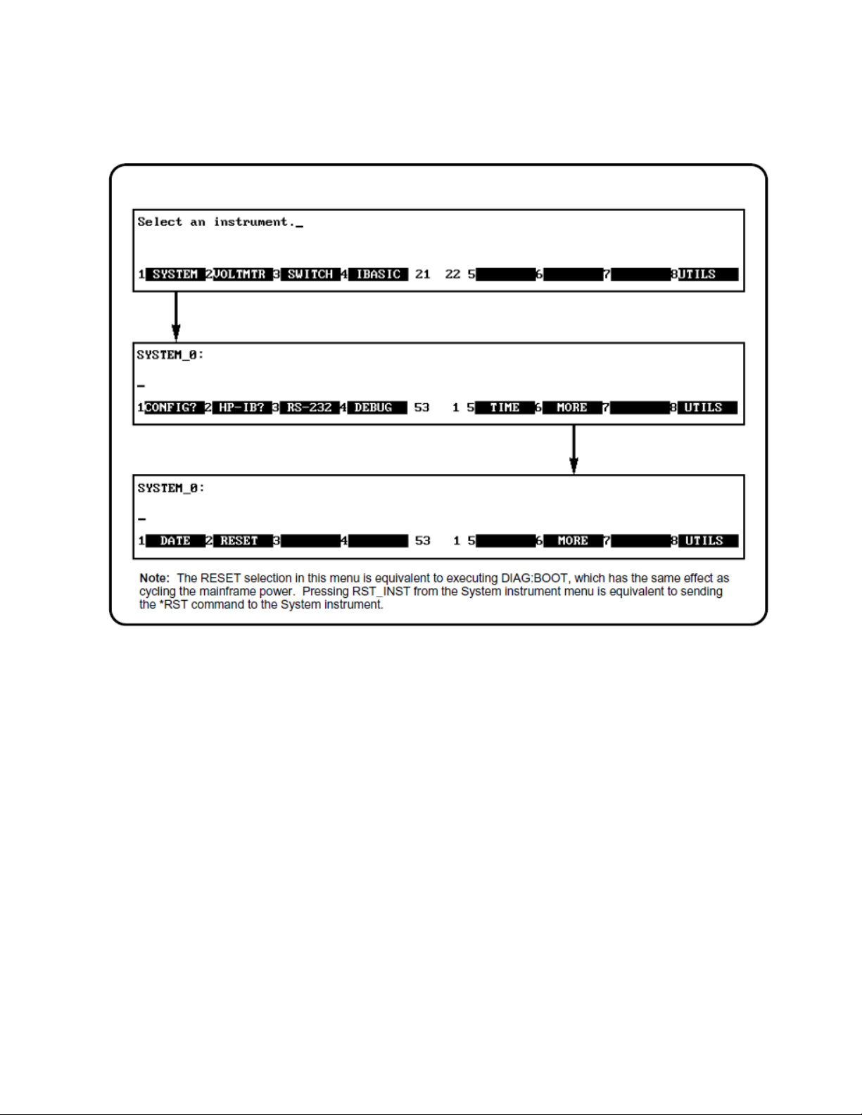
Using Display Terminal Menus Using the Display Terminal Interface
Figure 3-9 Resetting the System
Keysight E1406A User Manual and SCPI Programing Guide 89
Page 90

Using the Display Terminal Interface Using Display Terminal Menus
Using the Loader Instrument
The Loader instrument appears on the Select an instrument menu when the
Flash ROMS Run/Load switch on the front of the Keysight E1406A Command
Module is set to “Load”. This instrument allows you to:
– Read the command module GPIB address
– Configure the RS-232 port(s)
– Set the system clock and calendar
– Reset the system
Using the Switchbox Menu
The instrument menus allow you to access the most-used instrument functions
or to monitor an instrument (monitor mode) while it is being controlled from
remote. The Switchbox menu is used as an example to show you how to use the
instrument menus. Menus are available for many, but not all, instruments. See
your instrument user’s manual for more information on a particular instrument’s
menu. The Switchbox menu allows you to:
– Open and close channels
– Scan channels
– Display module (card) type and description
– Reset a selected switch module
– Monitor a switchbox
Selecting the Switchbox
To select the Switchbox, press the function key (f1 - f5) which corresponds to the
label SWITCH in the Select an instrument menu. (If the Select an instrument
menu is not being displayed press UTILS then SEL_INST.)
After you press the function key for SWITCH, the screen may
show: Select SWITCH at logical address:_ while the function key
labels show two or more logical addresses. This means more than
one switchbox is installed in the mainframe. To select one of the
switchboxes, press the function key for the logical address key
label.
Figures 3-10 through 3-13 show how to use the switchbox menu. Keep the
following points in mind when using the menu:
– The card number identifies a module within the switchbox. The module
with the lowest logical address is always card number 01. The module with
the next successive logical address is card number 02, and so on.
90 Keysight E1406A User Manual and SCPI Programing Guide
Page 91

Using Display Terminal Menus Using the Display Terminal Interface
– The @ character is required preceding a channel list when executing a
switchbox command from the terminal interface or remote. When entering
a channel list in response to a menu prompt, however, do not precede it
with the @ character. Doing so causes a syntax error.
Figure 3-10Opening and Closing Channels
Keysight E1406A User Manual and SCPI Programing Guide 91
Page 92

Using the Display Terminal Interface Using Display Terminal Menus
Figure 3-11Scanning Channels
92 Keysight E1406A User Manual and SCPI Programing Guide
Page 93

Using Display Terminal Menus Using the Display Terminal Interface
Figure 3-12Displaying Card Type and Description or Resetting Card
Keysight E1406A User Manual and SCPI Programing Guide 93
Page 94

Using the Display Terminal Interface Using Display Terminal Menus
Monitor Mode
Monitor mode displays the status of an instrument while it is being controlled
from remote. Monitor mode is useful for debugging programs. You can place an
instrument in monitor mode using terminal interface menus, or by executing the
DISP:MON:STAT ON command from the terminal interface or by remote. Pressing
most terminal interface keys will automatically exit monitor mode and return to
the instrument menu. However, you can use the left and right arrow keys in
monitor mode to view long displays.
Enabling monitor mode slows instrument operations. If the timing
or speed of instrument operations is critical (such as making
multimeter readings at a precise time interval), you should not
use monitor mode.
Figure 3-13Selecting Monitor Mode
94 Keysight E1406A User Manual and SCPI Programing Guide
Page 95

Using Display Terminal Menus Using the Display Terminal Interface
Table 3-1 shows the status annunciators that may appear in the bottom line of
the screen in monitor mode. Some instruments also have device-specific
annunciators (see your specific module user’s manual for more information).
Table 3-1 Monitor Mode Display Annunciators
Annunciator Description
mon
busy
err
srq
The instrument is in monitor mode.
The instrument is executing a command.
An error has occurred (see “Reading Error Messages” below). A
service request has occurred.
Reading Error Messages
Whenever the screen is showing the err annunciator, an error has occurred for
the instrument being monitored. You can read the error message, although doing
so cancels monitor mode. To read an error message, type SYST:ERR? (followed
by pressing the Return key):
The error message will be displayed in the bottom line of the Text Output Area.
To see if another error was logged, repeat the SYST:ERR? command by pressing
UTILS, RCL_PREV, then Return.
After you have read all the error messages, executing the SYST:ERR? command
causes the screen to show: +0,"No error". After reading the error message(s),
press the f1 key to return to monitor mode.
Keysight E1406A User Manual and SCPI Programing Guide 95
Page 96

Using the Display Terminal Interface Executing Commands
Executing Commands
From the terminal interface, you can type and execute IEEE 488.2 common
commands and SCPI commands for the instrument presently selected by the
Select an instrument menu. (However, you cannot execute a command when the
screen is requesting that you input information.) This is particularly useful for
accessing functions not available in an instrument’s menu. For example, assume
you want to program the Keysight E1411B 5 1/2-Digit Multimeter for 10 DC
voltage measurements. To specify 10 measurements you must type in the
necessary command since the command is not on the multimeter menu. After
selecting the VOLTMR menu, type the following commands and press the Return
key after each command.
CONF:VOLT:DC
SAMP:COUN 10
READ?
These commands configure the multimeter, specify 10 measurements, and
display the readings on the terminal.
Editing the Terminal Display
The screen editing keys allow you to edit user-entered data or commands. When
editing, the screen is in insert mode. That is, typed characters will be inserted
into the string at the present cursor position.
The key labels shown are found on all HP terminals (except HP
terminals supporting ANSI terminal protocol). See “Ung
Supported Terminals” for equivalent key functions on your
terminal.
96 Keysight E1406A User Manual and SCPI Programing Guide
Page 97
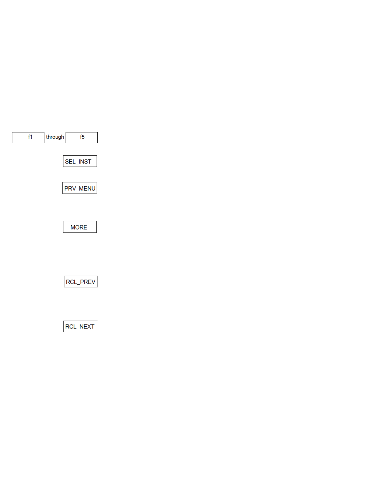
General Key Descriptions Using the Display Terminal Interface
General Key Descriptions
This section explains the function of each of the terminal interface’s menu, menu
control, and editing keys. If a key is not functional in a particular situation,
pressing that key does nothing except to cause a beep.
Menu and Menu Control Keys
Label menu choices for corresponding function keys.
Returns to the Select an instrument menu.
Returns to the previous menu level within an instrument menu or escapes from
an input prompt. When you reach the top of an instrument’s menu, the
PRV_MENU label disappears.
The screen can show a maximum of five menu choices at a time. When there are
more than five menu choices, function key f6 becomes labeled MORE. Press
MORE to display the next group of choices. By repeatedly pressing MORE you
can display all groups of choices. After you have displayed all groups of choices,
pressing MORE again returns to the first group of choices.
Recalls the last command entered from the terminal interface. After recalling a
command, it can be edited or re-executed. You can recall from a stack of
previously executed commands by repeatedly pressing RCL_PREV. When you
reach the bottom of the stack (the last line in the buffer), pressing RCL_PREV
does nothing except to cause a beep.
Recalls commands in the opposite order to that of RCL_PREV. Pressing
RCL_NEXT does nothing until you have pressed RCL_PREV at least twice.
Recalls the last SCPI command generated by a menu operation. For example,
reading the time using the menus (SYSTEM, TIME, READ) generates and
executes the SYST:TIME? SCPI command. A recalled command can be executed
by pressing the Return key. You can edit a recalled command before you execute
it.
Keysight E1406A User Manual and SCPI Programing Guide 97
Page 98

Using the Display Terminal Interface General Key Descriptions
Instrument Control Keys
Resets only the selected instrument (equivalent of executing *RST). RST_INST
also clears the instrument’s terminal interface and remote input and output
buffers. RST_INST is the only terminal interface key that can affect an instrument
being operated from remote.
Clears the terminal interface input and output buffers (remote buffers are not
cleared) of the selected instrument and returns to the top level of the instrument
menu. Press CLR_INST whenever an instrument is busy, is not responding to
terminal interface control, or to abort a command being entered from the
terminal interface.
Editing Keys
Moves the cursor one character space to the right while leaving characters
intact.
Moves the cursor one character space to the left while leaving characters intact.
Erases the character at the present cursor position (for user-entered data only).
Erases all characters from the present cursor position to the end of the input line
(for user-entered data only).
Other Keys
Selects alternate key definitions. These CTRL key sequences provide short- cuts
to some of the menu sequences and also provide some functions not directly
available from dedicated terminal keys. Some alternate key definitions are:
CTRL-R = Instrument Reset
CTRL-C = Clear Instrument
CTRL-D = Select an instrument menu.
See Table 3-3 for a complete list of all control sequence functions. Users of the
optional IBASIC interpreter should refer to their IBASIC manual set for additional
editing functions.
98 Keysight E1406A User Manual and SCPI Programing Guide
Page 99

Using Supported Terminals Using the Display Terminal Interface
Using Supported Terminals
The display terminal interface supports several popular terminal brands and
models. This chapter will show you how to access all of the terminal interface
functions described previously using your supported terminal.
The Supported Terminals
The following list names the supported terminals and shows where to go for
more information. If your terminal is not named in this list, see “Using Other
Terminals”.
– HP 700/92 Menu tutorial
– HP 700/94 Menu tutorial
– HP 700/22 See this page
– HP 700/43 and WYSE WY-30
The keyboard guides provided for the listed terminals may be removed or copied,
and placed near your keyboard while you go through the menu tutorial sections.
Using the HP 700/22
The HP 700/22 terminal emulates the DEC VT100 or VT220 terminals. Some
functions of the display terminal interface have been mapped into keys with
other labels. A keyboard map is provided for each of the emulation models. Use
these keyboard maps to help locate the terminal interface functions.
Keysight E1406A User Manual and SCPI Programing Guide 99
Page 100

Using the Display Terminal Interface Using Supported Terminals
VT100 Key Map
The symbols shown in the upper left corner of key each are now mapped with the
function labeled in the center of each key.
Selecting VT100 Mode
To use the HP 700/22 in VT100 mode, press the Set-Up key and set the following
configuration:
Fields Value
Terminal Mode EM100, 7 bit Ctrls
Columns 80
EM100 ID EM100
Inhibit Auto Wrap YES
VT220 Key Map
The function keys that are normally labeled f6 through f14 are now labeled:
100 Keysight E1406A User Manual and SCPI Programing Guide
 Loading...