

Page 1

User’s Guide
Keysight DAQ970A
Data Acquisition System
Distributed by:
dataTec ▪ Ferdinand-Lassalle -Str. 52 ▪ 72770 Reutlingen ▪ Tel. 07121 / 51 50 50 ▪ Fax 07121 / 51 50 10 ▪ info@datatec.de ▪ ww w.datatec.de
Page 2

Notices 6
Copyright Notice 6
Manual Part Number 6
Edition 6
Published by 6
Software Revision 6
Warranty 7
Technology Licenses 7
Restricted Rights Legend 7
Waste Electrical and Electronic Equipment (WEEE) 7
Declarations of Conformity 8
Safety and Regulatory Information 9
Safety Considerations 9
Safety Symbols and Regulatory Markings 11
South Korean Class A EMCDeclaration 13
Safety and EMC Requirements 14
Environmental Conditions 14
1 Introduction to the Instrument 16
Instrument at a Glance 17
Front Panel at a Glance 18
Instrument Annunciators 19
Rear Panel at a Glance 20
Plug-In Modules at a Glance 21
Dimension Diagram 22
Remote Interface Configuration 23
Keysight IOLibraries Suite 23
LAN Settings 23
LANServices 29
Set to Defaults 30
LAN Reset 30
Web Interface 30
More about IP addresses and dot notation 30
USB Settings 30
Technical Connection Details 32
LAN Configuration Procedure 33
Firmware Update 35
Contacting Keysight Technologies 36
2 Quick Start 37
Prepare Instrument for Use 38
Module Wiring Connection and Installation 39
Connect Power and I/O Cables 43
To turn on the instrument 43
Power-on self test 43
To turn off the instrument 43
Use the Built-in Help System 44
View the list of help topics 44
View the help information for a front panel key 45
View the instrument information 45
Adjust the Carrying Handle 46
Rack Mounting the Instrument 47
Keysight BenchVue Data Acquisition (DAQ) Software 49
2 Keysight DAQ970A User's Guide
Page 3

BenchVue Data Acquisition (DAQ) Software Licensing 49
3 Features and Functions 51
System Overview 53
Data Acquisition System Overview 53
Signal Routing and Switching 56
Measurement Input 58
Scanning 60
Scanning with external instruments 61
The multifunction module 62
Control Output 63
Front Panel Menu Reference 67
[Scan] Key 69
[Monitor] Menu 70
Number 70
Bar Meter 71
Trend Chart 72
Histogram 73
[Home] Menu 75
Strain Offset 75
Alarm Output 77
Help 78
User Settings 78
[View] Menu 82
Views scanned memory readings (List, Trend Chart, Histogram, Statistics) 82
View alarm queue 86
View error queue 86
View number of relay cycles 87
[Channel] Menu Overview 88
Measurements on Multiplexer Modules 89
Temperature 90
Strain 96
DC Voltage 109
AC Voltage 111
DC Current 113
Resistance 115
Frequency and Period 118
Diode 119
Capacitance 120
DAQM907A Multifunction Module - Overview 120
Digital I/O (DIO) Channels (Channel 01 and 02) 121
Totalizer Channel 124
DAC output and sense channels (Channels 04 through 07) 125
Computed Channel 128
Basic math 128
Polynomial fifth order 129
Statistics 130
Scanning with External Instruments 133
Channel Labeling 134
[Interval] Menu 134
Selecting the trigger source 135
Selecting the output trigger polarity 135
Specifying number of sweeps in the scan 136
Keysight DAQ970A User's Guide 3
Page 4

[Math] Menu 137
mX+b Scaling 137
% Scaling 138
dBm Scaling 138
dB Scaling 138
[Copy] Menu 140
Copy/paste from a single channel to a single channel (one-to-one) 140
Copy/paste from a single channel to multiple channels (one-to-many) 141
Copy/paste from multiple channels to multiple channels (many-to-many) 142
[Alarm] Menu 144
Configuring alarm limits on multiplexer module 144
Configuring Alarm Limits with the Multifunction Module 145
Alarm Limit Indications 146
[Utility] Menu 148
Self-Test 148
Autocalibration 148
Calibrate 149
Security 150
Admin 151
[Module] Menu 152
Overview of the scan list for the module 152
Perform a module reset 152
Module labeling 153
[Save Recall] Menu 154
Manage Files 154
Save 156
Recall 158
Set to Defaults 158
Factory Reset 159
Log to USB 159
Web Interface 162
Home page 162
Control Instrument page 163
Configure LAN page 163
Module Overview 165
DAQM900A 20-Channel FET Multiplexer Module 166
DAQM901A 20-Channel Armature Multiplexer Module 167
DAQM902A 16-Channel Reed Multiplexer Module 168
DAQM903A 20-Channel Actuator/General-Purpose Switch Module 169
DAQM904A 4x8 Two-Wire Matrix Switch 170
DAQM905A Dual 1:4 RF Multiplexer (50 Ω) Module 171
DAQM907A multifunction module 172
DAQM908A 40-channel single-ended multiplexer 174
4Measurement Tutorials 175
System Cabling and Connections 176
Cable specifications 176
Grounding techniques 178
Shielding techniques 179
Separation of high-level and low-level signals 179
Source of system cabling errors 179
Measurement Fundamentals 183
The Internal DMM 183
4 Keysight DAQ970A User'sGuide
Page 5

Temperature Measurements 184
DC Voltage Measurements 193
AC Voltage Measurements 197
Current Measurements 202
Resistance Measurements 204
Strain Gage Measurements 206
Frequency and Period Measurements 209
Capacitance Measurements 210
Low-Level Signal Multiplexing and Switching 211
One-Wire (Single-Ended) Multiplexers 212
Two-Wire Multiplexers 212
Four-Wire Multiplexers 213
Signal Routing and Multiplexing 214
Sources of Error in Multiplexing and Switching 214
Actuators and General-Purpose Switching 216
Matrix Switching 218
RF Signal Multiplexing 220
Multifunction Module 222
Digital Input 222
Digital Output 224
Using an External Pull-Up 225
Driving External Switches 225
Totalizer 226
Totalizer Errors 227
Analog Output (DAC) 227
Relay Life and Preventive Maintenance 229
Keysight DAQ970A User's Guide 5
Page 6

Notices
Notices
Copyright Notice
© Keysight Technologies, 2018
No part of this manual may be reproduced in any form or by any means (including electronic storage and
retrieval or translation into a foreign language) without prior agreement and written consent from Keysight
Technologies as governed by United States and international copyright laws.
Manual Part Number
DAQ97-90000
Edition
Edition 1, November 1 2018
Published by
Keysight Technologies
Bayan Lepas Free Industrial Zone
11900 Bayan Lepas, Penang
Malaysia
Software Revision
The latest firmware is available at www.keysight.com/find/DAQ970Afirmware.
The latest product documentation is available at www.keysight.com/find/DAQ970Amanuals.
A portion of the software in this product is licensed under terms of the General Public License Version 2
(GPLv2). The text of the license and source code can be found at www.keysight.com/find/GPLV2.
This product uses Microsoft Windows CE. Keysight highly recommends that all Windows-based computers
connected to Windows CE instruments use current anti-virus software. For more information, see
www.keysight.com/find/DAQ970A.
6 Keysight DAQ970A User'sGuide
Page 7

Notices
Warranty
THE MATERIAL CONTAINED IN THIS DOCUMENT IS PROVIDED "AS IS", AND IS SUBJECT TO BEING
CHANGED, WITHOUT NOTICE, IN FUTURE EDITIONS. FURTHER, TO THE MAXIMUM EXTENT PERMITTED
BY APPLICABLE LAW, KEYSIGHT DISCLAIMS ALL WARRANTIES, EITHER EXPRESS OR IMPLIED, WITH
REGARD TO THIS MANUAL AND ANY INFORMATION CONTAINED HEREIN, INCLUDING BUT NOT
LIMITED TO THE IMPLIED WARRANTIES OF MERCHANTABILITY AND FITNESS FOR A PARTICULAR
PURPOSE. KEYSIGHT SHALL NOT BE LIABLE FOR ERRORS OR FOR INCIDENTAL OR CONSEQUENTIAL
DAMAGES IN CONNECTION WITH THE FURNISHING, USE, OR PERFORMANCE OF THIS DOCUMENT OR
OF ANY INFORMATION CONTAINED HEREIN. SHOULD KEYSIGHT AND THE USER HAVE A SEPARATE
WRITTEN AGREEMENT WITH WARRANTY TERMS COVERING THE MATERIAL IN THIS DOCUMENT THAT
CONFLICT WITH THESE TERMS, THE WARRANTY TERMS IN THE SEPARATE AGREEMENT SHALL
CONTROL.
Technology Licenses
The hardware and/or software described in this document are furnished under a license and may be used
or copied only in accordance with the terms of such license.
Restricted Rights Legend
If software is for use in the performance of a U.S. Government prime contract or subcontract, Software is
delivered and licensed as "Commercial computer software" as defined in DFAR 252.227-7014 (June 1995),
or as a "commercial item" as defined in FAR 2.101(a) or as "Restricted computer software" as defined in FAR
52.227-19 (June 1987) or any equivalent agency regulation or contract clause. Use, duplication or disclosure of Software is subject to Keysight Technologies’ standard commercial license terms, and non-DOD
Departments and Agencies of the U.S. Government will receive no greater than Restricted Rights as
defined in FAR 52.227-19(c) (1-2) (June 1987). U.S. Government users will receive no greater than Limited
Rights as defined in FAR 52.227-14 (June 1987) or DFAR 252.227-7015 (b)(2) (November 1995), as applicable in any technical data.
Waste Electrical and Electronic Equipment (WEEE)
This product complies with the European WEEE directive marketing requirement. The affixed product label
(see below) indicates that you must not discard this electrical/electronic product in domestic household
waste.
Product Category: With reference to the equipment types in the European WEEE directive Annex 1, this
product is classified as "Monitoring and Control instrumentation" product. Do not dispose in domestic
household waste.
To return unwanted products, contact your local Keysight office, or see http://-
about.keysight.com/en/companyinfo/environment/takeback.shtml for more information.
Keysight DAQ970A User's Guide 7
Page 8

Notices
Declarations of Conformity
Declarations of Conformity for this product and for other Keysight products may be downloaded from the
Web. Go to https://regulations.about.keysight.com/DoC/default.htm, you can then search by product
model number to find the latest Declaration of Conformity.
8 Keysight DAQ970A User'sGuide
Page 9

Safety and Regulatory Information
Safety and Regulatory Information
Safety Considerations
The following general safety precautions must be observed during all phases of operation, service, and
repair of this instrument. Failure to comply with these precautions or with specific warnings elsewhere in
this manual violates safety standards of design, manufacture, intended use of the instrument, and could result in electrical shock or injury. Keysight Technologies assumes no liability for the customer's failure to comply with these requirements.
Keysight DAQ970A User's Guide 9
Page 10

Safety and Regulatory Information
BEFORE APPLYING POWER
Verify that all safety precautions are taken. Make all connections to the unit before applying power.
GROUNDTHEINSTRUMENT
This product is provided with protective earth terminals. To minimize shock hazard, the instrument
must be connected to the ac power mains through a grounded power cable, with the ground wire family connected to an electrical ground (safety ground) at the protective (grounding) conductor. Disconnection of the protective earth terminal will cause a potential shock hazard that could result in
personal injury.
BEFORE POWER ON AND OFF
Before powering on the instrument, make sure all signal sources connected to modules are turned
off. Turn on signal sources after the instrument is powered on. Turn off signal sources before the
instrument is powered off.
DONOTREMOVETHEINSTRUMENTCOVER
Only qualified, service-trained personnel who are aware of the hazards involved should remove the
instrument covers. Always disconnect the power cable and any external circuits before removing the
instrument cover.
MODULE COVERS
Always replace module covers after terminal wiring and before inserting into mainframe.
DONOTOPERATEINAN EXPLOSIVEATMOSPHERE
Do not operate the instrument in the presence of flammable gases or fumes.
DONOTMODIFYTHEINSTRUMENT
Do not install substitute parts or perform any unauthorized modification to the product. Return the
product to a Keysight Sales and Service Office for service and repair to ensure that safety features are
maintained.
DONOT MEASUREMORE THAN THE RATED VOLTAGE
Maximum voltage as marked on each module is as below:
a) DAQM900A: 120 Vrms
b) DAQM901A, DAQM902A, DAQM903A, DAQM904A, DAQM908A: 300 Vrms
c) DAQM905A, DAQM907A: 42 Vpk
DO NOT CONNECT ANY MODULE CHANNELS TO MAINS
Measurement category of the instrument is rated as CAT 'Others', terminals should not be directly connected to the mains.
ACPOWERCORD
Removal of the AC power cord is the disconnect method to remove power from the instrument. Be
sure to allow for adequate access to the power cord to permit disconnection from ACpower. Use only
the Keysight specified power cord for the country of use or one with equivalent ratings.
10 Keysight DAQ970A User'sGuide
Page 11

Safety and Regulatory Information
SELF-TEST
Before measuring any hazardous voltage or current, run the *TST? query from the remote interface,
and read the result to verify that the instrument is performing properly. The *TST? query is a self-test
that returns +0 if the instrument passes and +1 if the instrument fails. You can also perform this
query from the front panel by pressing
sure that the instrument is repaired and passes the self-test before continuing.
INCASEOFDAMAGE
Instruments that appear damaged or defective should be made inoperative and secured against unintended operation until they can be repaired by qualified service personnel.
This is a sensitive measurement apparatus by design and may have some performance loss when
exposed to ambient continuous electromagnetic phenomenon. Measurement Considerations – use
shielded or twisted cable, use common mode choke, ferrite clamp and damping resistor before the
input to DAQ970A.
CLEANING
To prevent electrical shock, disconnect the instrument from AC mains power before cleaning. Clean
the outside of the instrument using a soft, lint-free, cloth slightly dampened with water. Do not use
detergent or solvents. Do not attempt to clean internally. If needed, contact a Keysight Technologies
Sales and Service Office to arrange for proper cleaning to ensure that safety features and performance
are maintained.
[Utility]>Self Test>Quick Test
. If this self-test fails, make
Connect USB cable with ferrite core to the rear panel USB port of the instrument.
Safety Symbols and Regulatory Markings
Symbol Description
Alternating current (AC).
Protective earth (ground) terminal.
Earth (ground) terminal.
Caution, risk of danger (refer to the manual for specific Warning or Caution information).
Frame or chassis (ground) terminal.
Instrument cable lock.
Keysight DAQ970A User's Guide 11
Page 12

Safety and Regulatory Information
Symbol Description
This product is marked with the ACMA RCMmark for compliance in Australia/New Zealand. A copy
of the Manufacturer's Australia Declaration of Conformity for this instrument can be obtained by contacting your local Keysight Technologies Sales Representative.
This symbol indicates the time period during which no hazardous or toxic substance elements are
expected to leak or deteriorate during normal use. Forty years is the expected useful life of the
product.
The CE mark is a registered trademark of the European Community. This CE mark shows that the
product complies with all the relevant European Legal Directives.
ICES/NMB-001 - This ISM device complies with the Canadian ICES-001.
Cet appareil ISM est conforme a la norme NMB-001 du Canada.
ISM GRP 1-A - This is an Industrial Scientific and Medical (ISM) Group 1 Class A product.
The CSA mark is a registered trademark of the Canadian Standards Association, with the 'C' and
'US' subscript indicates the instrument is certified to the applicable Canadian and United States of
America standards respectively.
This symbol is a South Korean Class A EMCDeclaration, with the product identification code
"MSIP-REM-Kst-GM16412".
MSIP - Identification of Broadcasting and communications equipment.
REM - Identification of basic certification information.
Kst - Identification of applicant's information
GM16412 - Product identification.
This is a Class A instrument suitable for professional use and in electromagnetic environment outside of the home.
The WARNING sign denotes a hazard. It calls attention to a procedure, practice, or the like, which,
if not correctly performed or adhered to, could result in personal injury. Do not proceed beyond a
WARNING sign until the indicated conditions are fully understood and met.
The CAUTION sign denotes a hazard. It calls attention to an operating procedure, or the like, which,
if not correctly performed or adhered to, could result in damage to or destruction of part or all of the
product. Do not proceed beyond CAUTION sign until the indicated conditions are fully understood
and met.
The NOTE sign denotes important information. It calls attention to a procedure, practice, condition
or the like, which is essential to highlight.
12 Keysight DAQ970A User'sGuide
Page 13

Safety and Regulatory Information
South Korean Class A EMCDeclaration
Information to the user:
This instrument has been conformity assessed for used in business environments. In a residential environment this equipment may caused radio interference.
This EMC statement applies to the equipment only for use in business environment.
사 용 자 안 내 문
이 기 기 는 업 무 용 환 경 에 서 사 용 할 목 적 으 로 적 합 성 평 가 를 받 은 기 기 로 서 가 정 용 환 경
에 서 사 용 하 는 경 우 전 파 간 섭 의 우 려 가 있 습 니 다 .
사용자 안내문은"업무용 방송통신기자재"에 만 적 용 한 다 .
Keysight DAQ970A User's Guide 13
Page 14

Safety and Regulatory Information
Safety and EMC Requirements
This instrument is designed to comply with the following safety and EMC requirements:
Safety compliance
l IEC 61010-1:2010/EN 61010-1:2010; IEC 61010-2-030:2010/EN61010-2-030:2010
l Canada: CAN/CSA-C22.2 No.61010-1-12; CAN/CSA-C22.2 No. 61010-2-030-12
l USA: ANSI/UL Std. No. 61010-1:2012; ANSI/UL Std No.61010-2-030:2012
EMC compliance
l IEC61326-1:2012 / EN 61326-1:2013
l Canada: ICES/NMB-001:2006
l Australia/New Zealand: AS/NZS CISPR 11:2011
l South Korea RRA Notice 2016-24
Environmental Conditions
Keysight DAQ970A is designed for indoor use and in an area with low condensation. Table below shows the
general environmental requirements for this instrument.
Environmental condition Requirement
Temperature
Operating condition: 0 °C to 55 °C
Storage condition: –40 °C to 70 °C
Humidity
Operating condition: Up to 80% RH at 40 °C (non-condensing), decreasing linearly to
50%RH at 55 °C (non-condensing)
Storage condition: Up to 50% RH at 55 °C (non-condensing)
Altitude Up to 3000 m
Pollution degree
2
14 Keysight DAQ970A User'sGuide
Page 15

Safety and Regulatory Information
Keysight DAQ970A User's Guide 15
Page 16

1 Introduction to the Instrument
1 Introduction to the Instrument
Instrument at a Glance
Front Panel at a Glance
Instrument Annunciators
Rear Panel at a Glance
Plug-In Modules at a Glance
Dimension Diagram
Remote Interface Configuration
LANConfiguration Procedure
Firmware Update
Contacting Keysight Technologies
This chapter introduces the overview and basic functionality of the
DAQ970A.
16 Keysight DAQ970A User'sGuide
Page 17

1 Introduction to the Instrument
Instrument at a Glance
The DAQ970A combines precision measurement capability with flexible signal connections for your production and development test systems. Three module slots are built into the rear of the instrument to
accept any combination of data acquisition or switching modules. The combination of USB data logging
and data acquisition features make this instrument a versatile solution for your testing requirements now
and in the future.
Easily display, save, and document your measurement results
l High usability with an intuitive, menu driven user interface.
l Histogram, trend chart, meter, and numeric views on a high-resolution color display.
l Supported on both LANand USBinterfaces.
l Drag and drop, driverless USB connectivity.
Convenient data logging features
l Direct measurement of temperature (thermocouples, RTDs, and thermistors), strain, DC
voltage, AC voltage, 2-wire and 4-wire resistance, frequency, period, diode, capacitance, DC
current, and AC current.
l Patented, metrology-level performance that serves as the foundation for all measurements.
l Interval scanning with storage of up to 100,000 time-stamped readings.
l Independent channel configuration with function, measurement scaling, and alarm limits
available on a per-channel basis.
l Intuitive user interface with knob cursor navigation keypad, data entry from both softkeys
(menu keys inside the screen view) and hardkeys (menu keys in front of the instrument).
l Portable, rugged case with non-skid feet.
l BenchVue Data Acquisition (DAQ) software for Microsoft
®
Windows®available for download
from www.keysight.com/find/benchvue.
Flexible data acquisition/switching features
l Up to 60 channels per instrument (120 single-ended channels).
l Reading rates are more than 5,000 readings per second on a single channel and scan rates up
to 450 channels per second.
l Choice of multiplexing, matrix, general-purpose Form C switching, RF switching, digital I/O,
totalize, DACoutput, and DAC readback functions.
l Built-in Web Interface for monitoring and controlling the instrument via a Web browser.
Programming language
l Compatible with SCPI (Standard Commands for Programmable Instruments) programming
language.
Keysight DAQ970A User's Guide 17
Page 18

1 Introduction to the Instrument
Front Panel at a Glance
Label Description
1 USB port
2 On/Standby switch with LEDindicator
3 Display
4 Softkeys
5 Measurement operation menu (to control the initiation of the measurements)
6 Measurement configuration menu (to set parameters for measurements)
7 Knob
8 Cursor navigation keypad
Front panel key
Press the key to return the instrument into local control when the instrument is in remote
(indicated by the annunciator).
18 Keysight DAQ970A User'sGuide
Page 19
1 Introduction to the Instrument
Instrument Annunciators
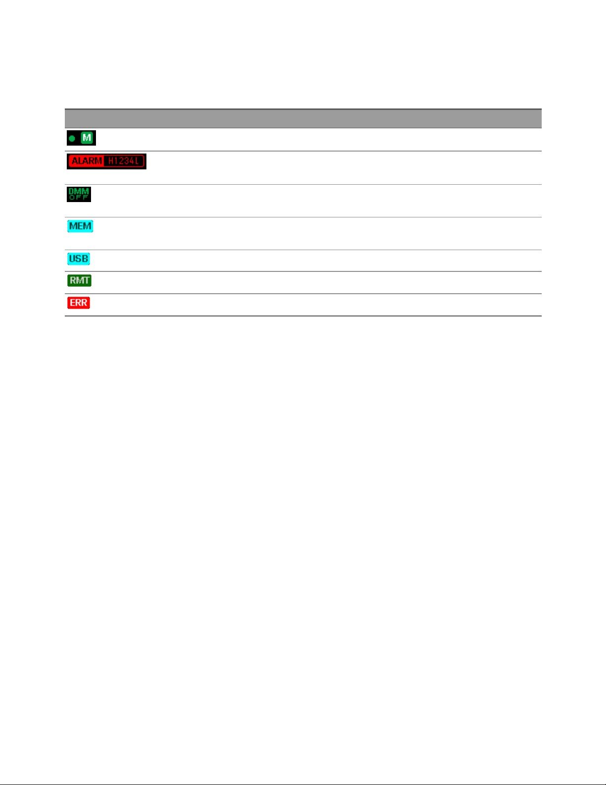
The table below shows the various annunciators that are available on the DAQ970A. The annunciators will
be shown on the top of the display when the corresponding conditions are met.
Annunciator Description
l Monitor mode is enabled.
l
ALARM- Alarms are present in the alarm queue.
l
H1234L - A High or Low alarm condition has occurred.
l Internal DMMis disabled. Instrument is configured for an external scan interval when
DMMis Off.
l Reading memory overflowed at 100,000 readings. New readings will overwrite the oldest
readings.
l A USB drive is inserted in the front panel USB host port.
l Instrument is in remote (remote interface).
l
Errors are present in the error queue. Press [View] > Errors to view the list of errors.
Keysight DAQ970A User's Guide 19
Page 20

1 Introduction to the Instrument
Rear Panel at a Glance
Label Description
1 Slot identifier (100, 200, 300)
2 External trigger input, alarm outputs, channel advance input, and channel close output
3 AC mains input
4 Instrument cable lock
5 LAN interface connector
6 Chassis ground screw
7 USB interface connector
20 Keysight DAQ970A User'sGuide
Page 21

1 Introduction to the Instrument
Plug-In Modules at a Glance
The DAQ970A offers a complete selection of plug-in modules to provide a high quality measurement,
switching, and control capabilities. For more details, see Module Overview.
Supported modules on the DAQ970A:
l DAQM900A 20-Channel FET Multiplexer Module
l DAQM901A 20-Channel Armature Multiplexer Module
l DAQM902A 16-Channel Reed Multiplexer Module
l DAQM903A 20-Channel Actuator/General-Purpose Switch Module
l DAQM904A 4x8 Two-Wire Matrix Switch Module
l DAQM905A Dual 1:4 RF Multiplexer (50 Ω) Module
l DAQM907A Multifunction Module
l DAQM908A 40-Channel Single-Ended Multiplexer Module
Refer to the product data sheet at http://literature.cdn.keysight.com/litweb/pdf/5992-3168EN.pdf
for a complete specifications on all the supported modules.
Keysight DAQ970A User's Guide 21
Page 22
1 Introduction to the Instrument
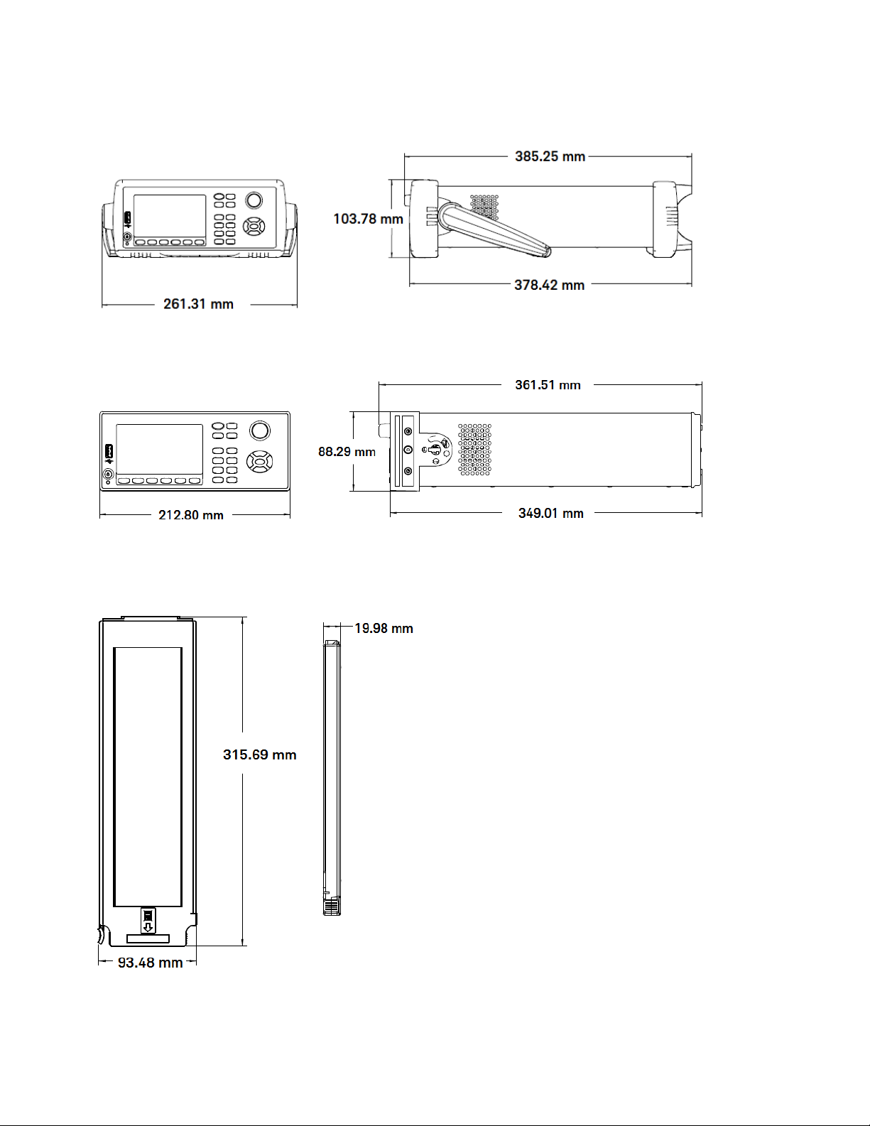
Dimension Diagram
Bench dimension:
Rack dimension:
Module dimension:
22 Keysight DAQ970A User'sGuide
Page 23

1 Introduction to the Instrument
Remote Interface Configuration
REMOTE OPERATION
When any channel is connected to a hazardous voltage source, the instrument and the device under
test should be supervised, following local EHS practices to restrict access.
If Secure mode is enabled, the instrument must be unlocked with the correct security code to perform
many of these actions. See Security for more information.
The DAQ970A supports remote interface communication over two interfaces: LANand USB. Both interfaces are "live" at power up when the instrument ships from the factory.
l
LAN Interface: By default, the DHCP (Dynamic Host Configuration Protocol) is on, a protocol
for assigning dynamic IP addresses to network devices, which may enable communication
over LAN. With dynamic addressing, a device can have a different IP address every time it connects to the network. See LAN Settings for more information.
l
USB Interface: Use the rear panel USB interface connector to communicate with the instru-
ment using your PC. See USB Settings for more information.
Keysight IOLibraries Suite
Ensure that the Keysight IOLibraries Suite is installed before you proceed for the remote interface
configuration.
Keysight IO Libraries Suite is a collection of free instrument control software that automatically discovers
instruments and allows you to control instruments over LAN and USB interfaces. For more information, or
to download the IO Libraries, go to www.keysight.com/find/iosuite.
LAN Settings
The following sections describe the primary front panel LAN configuration functions, including SCPI commands where applicable. In the DAQ970A Programming Guide, see "SYSTem Subsystem - Remote Interface Configuration Commands" for all LAN configuration commands.
Some LANsettings require you to cycle power to activate them. The instrument briefly displays a
message when this is the case. Observe the display closely as you change the LANsettings.
Enable or disable LANinterface
Front panel Remote interface
Press [Home] > User Settings > I/O > LAN
Set the softkey to On or Off
SYSTem:COMMunicate:ENABle {OFF | ON}, LAN
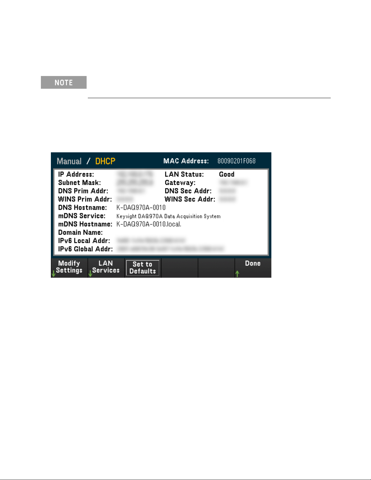
View the LANstatus, MACaddress, and current LAN configuration settings
Once the LAN interface is enabled, you can view the LANstatus, MAC address, and current
LANconfiguration settings from the front panel. The LAN status may be different from the front panel
Keysight DAQ970A User's Guide 23
Page 24
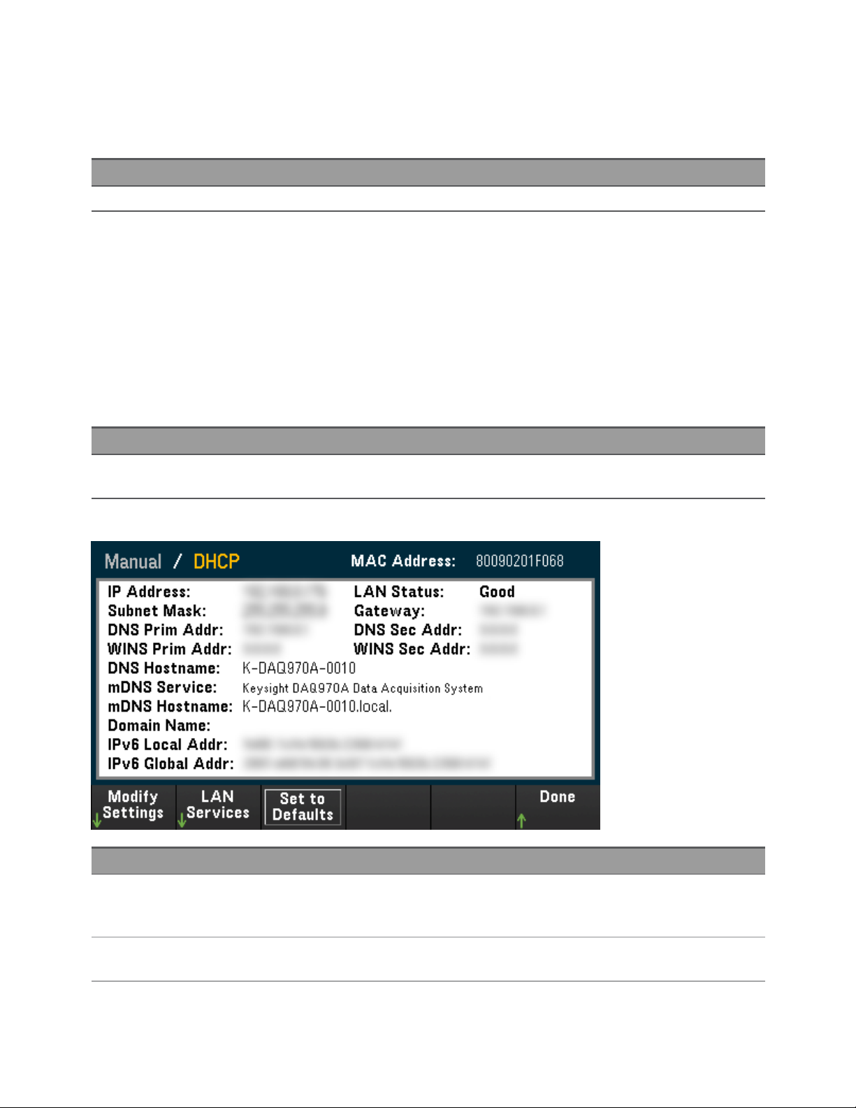
1 Introduction to the Instrument
configuration menu settings, which depends on the network configuration. If the settings are different, it is
because the network has automatically assigned its own settings. If the instrument goes into remote, all
LAN changes will be disabled and the display will go into a different screen. Re-selecting with LAN Settings
page willdisplay the new settings if a LAN restart took place.
Front panel Remote interface
Press [Home] > User Settings > I/O > LAN Settings (none)
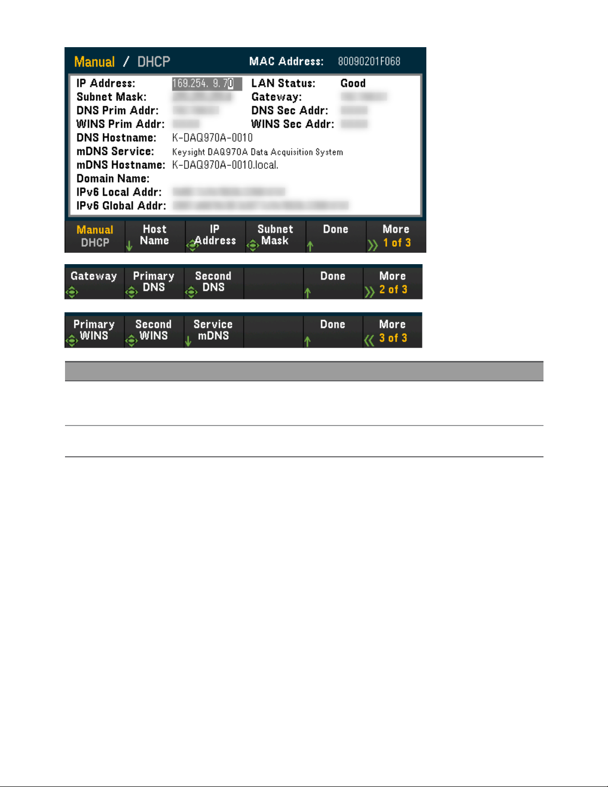
Modify Settings
As shipped from the factory, the instrument pre-configured settings should work in most LAN environments. To configure the LAN settings manually:
Manual/DHCP
The DHCP can automatically assign a dynamic IP address to a LAN device. This is typically the easiest way to
configure the instrument for LAN. This setting is non-volatile, it will not be changed by cycling power, factory reset (*RST command), or instrument present (SYSTem:PRESet command). Enabling the DHCP will disable the Manual setting, and vice versa.
Front panel Remote interface
Press [Home] > User Settings > I/O > LANSettings > Modify Settings.
SYSTem:COMMunicate:LAN:DHCP {OFF|ON}
To enable DHCP:
Step Front panel Remote interface
1 Press [Home] > User Settings > I/O > LANSettings > Modify
Settings.
Set the first softkey to DHCP.
2 If you change this parameter, you must press [Done] > [Apply
Changes] for the change to take effect.
SYSTem:COMMunicate:LAN:DHCP ON
SYSTem:COMMunicate:LAN:UPDate
To disable DHCP:
24 Keysight DAQ970A User'sGuide
Page 25
1 Introduction to the Instrument
Step Front panel Remote interface
1 Press [Home] > User Settings > I/O > LANSettings > Modify
Settings.
Set the first softkey to Manual.
2 If you change this parameter, you must press [Done] > [Apply
Changes] for the change to take effect.
SYSTem:COMMunicate:LAN:DHCP OFF
SYSTem:COMMunicate:LAN:UPDate
Host Name
IP Address
Subnet Mask
Gateway
Primary and Secondary DNS
Primary and Secondary WINS
Service mDNS
Host Name
A hostname is the host portion of the domain name, which is translated into an IP address.
Keysight DAQ970A User's Guide 25
Page 26

1 Introduction to the Instrument
Step Front panel Remote interface
1 Press [Home] > User Settings > I/O > LANSettings > Modify
SYSTem:COMMunicate:LAN:HOSTname
Settings.
Set the first softkey to Manual and press Host Name to enter
the hostname.
2 If you change this parameter, you must press [Done] > [Done]
SYSTem:COMMunicate:LAN:UPDate
> [Apply Changes] for the change to take effect.
Each instrument is shipped with a default host name with the format: K-modelnumber-serialnumber,
where modelnumber is the instrument’s 7-character model number (e.g. DAQ970A), and serialnumber is
the last five characters of the 10-character instrument serial number located on the label on the top of the
unit (e.g. 5678 if the serial number is MY12345678).
l The instrument receives a unique hostname at the factory, but you may change it. The host-
name must be unique on the LAN.
l The name must start with letter, other characters can be an upper or lower case letters,
numeric digits, or dashes "-".
l This setting is non-volatile, it will not be changed by cycling power, factory reset (*RST com-
mand), or instrument present (SYSTem:PRESet command).
IP Address
You can enter a static IP address for the instrument as a four-byte integer expressed in dot notation. Each
byte is a decimal value, with no leading zeros (for example, 169.254.2.20). Refer to "More about
IPAddresses and Dot Notation" for further details.
Step Front panel Remote interface
1 Press [Home] > User Settings > I/O > LANSettings > Modify
SYSTem:COMMunicate:LAN:IPADdress
Settings.
Set the first softkey to Manual and press IP Address to set the
desired IP address.
26 Keysight DAQ970A User'sGuide
Page 27

1 Introduction to the Instrument
Step Front panel Remote interface
2 If you change this parameter, you must press [Done] > [Apply
SYSTem:COMMunicate:LAN:UPDate
Changes] for the change to take effect.
l If DHCP is on, it attempts to assign an IP address to the instrument. If it fails, Auto-IP
attempts to assign an IP address to the instrument.
l Contact your LAN administrator to obtain an IP address.
l This setting is non-volatile, it will not be changed by cycling power, factory reset (*RST com-
mand), or instrument present (SYSTem:PRESet command).
Subnet Mask
Subnetting allows the LAN administrator to subdivide a network to simplify administration and minimize
network traffic. The subnet mask indicates the portion of the host address used to indicate the subnet.
Step Front panel Remote interface
1 Press [Home] > User Settings > I/O > LANSettings > Modify
SYSTem:COMMunicate:LAN:SMASk
Settings.
Set the first softkey to Manual and press Subnet Mask to set
the desired subnet mask address.
2 If you change this parameter, you must press [Done] > [Apply
SYSTem:COMMunicate:LAN:UPDate
Changes] for the change to take effect.
l Contact your LAN administrator to obtain an IP address.
l This setting is non-volatile, it will not be changed by cycling power, factory reset (*RST com-
mand), or instrument present (SYSTem:PRESet command).
Gateway
A gateway is a network device that connects networks. The default gateway setting is the IP address of the
instrument.
Step Front panel Remote interface
1 Press [Home] > User Settings > I/O > LANSettings > Modify
SYSTem:COMMunicate:LAN:GATEway
Settings.
Set the first softkey to Manual and press Gateway in the
second page of menu to set the desired gateway address.
2 If you change this parameter, you must press [Done] > [Apply
SYSTem:COMMunicate:LAN:UPDate
Changes] for the change to take effect.
l Do not set a gateway address when DHCP is enabled (factory default).
l Contact your LAN administrator to obtain an IP address.
l This setting is non-volatile, it will not be changed by cycling power, factory reset (*RST com-
mand), or instrument present (SYSTem:PRESet command).
Keysight DAQ970A User's Guide 27
Page 28

1 Introduction to the Instrument
Primary and Secondary DNS
A DNS (Domain Name Service) is an Internet service that translates domain names into IP addresses. The
DNS server address is the IP address of a server that performs this service.
Step Front panel Remote interface
1 Press [Home] > User Settings > I/O > LANSettings > Modify
SYSTem:COMMunicate:LAN:DNS[{1|2}]
Settings.
Set the first softkey to Manual and press Primary DNS or
Second DNS in the second page of menu to set the desired
Note: The [{1|2}] syntax indicates the type of primary (1) or
secondary (2) DNS server address.
gateway address.
2 If you change this parameter, you must press [Done] > [Apply
SYSTem:COMMunicate:LAN:UPDate
Changes] for the change to take effect.
l Normally, DHCP discovers the DNS address information; you only need to change this if
DHCP is unused or nonfunctional.
l Contact your LAN administrator to obtain an IP address.
l This setting is non-volatile, it will not be changed by cycling power, factory reset (*RST com-
mand), or instrument present (SYSTem:PRESet command).
Primary and Secondary WINS
A WINS (Windows Internet Name System) is a system that enables Windows to identify NetBIOS systems on
a TCP/IP network.
Step Front panel Remote interface
1 Press [Home] > User Settings > I/O > LANSettings > Modify
SYSTem:COMMunicate:LAN:WINS[{1|2}]
Settings.
Set the first softkey to Manual and press Primary WINS or
Second WINS in the third page of menu to set the desired gate-
Note: The [{1|2}] syntax indicates the type of primary (1)
and secondary (2) WINS server address.
way address.
2 If you change this parameter, you must press [Done] > [Apply
SYSTem:COMMunicate:LAN:UPDate
Changes] for the change to take effect.
l Normally, DHCP discovers the WINS address information; you only need to change this if
DHCP is unused or nonfunctional.
l Contact your LAN administrator to obtain an IP address.
l This setting is non-volatile, it will not be changed by cycling power, factory reset (*RST com-
mand), or instrument present (SYSTem:PRESet command).
Service mDNS
An mDNS (multicast Domain Name Service) is an Internet service that is registered with the selected naming service.
28 Keysight DAQ970A User'sGuide
Page 29

1 Introduction to the Instrument
Step Front panel Remote interface
1 Press [Home] > User Settings > I/O > LANSettings > Modify
LXI:MDNS:SNAMe:DESired
Settings.
Set the first softkey to Manual and press Service mDNS in the
third page of menu to set the desired gateway address.
2 If you change this parameter, you must press [Done] > [Done] >
SYSTem:COMMunicate:LAN:UPDate
[Apply Changes] for the change to take effect.
Each instrument is shipped with a default service name with the format:
Keysight Technologies_<modelNumber>_- serialNumber
where modelNumber is the instrument 7-character model number (DAQ970A) and product name (Data
Acquisition System), and serialNumber is the last five characters of the 10-character instrument serial number located on the label on top of the unit (e.g. 45678 if the serialnumber is MY12345678).
l The instrument receivesa unique mDNS service name at the factory, but you may change it.
The mDNS service name must be unique on the LAN.
l The name must start with letter, other characters can be an upper or lower case letters,
numeric digits, or dashes "-".
l This setting is non-volatile, it will not be changed by cycling power, factory reset (*RST com-
mand), or instrument present (SYSTem:PRESet command).
LAN Restart
Any modification on the LAN settings described above will restart the LANafter pressing Apply Changes.
This feature restarts the networking using ALL current LANsettings. LAN restart does not clear the Web
Interface password.
Remote interface: LXI:REStart
LANServices
Enables (On) or disables (Off) LAN services on the instrument.
Step Front panel Remote interface
1 Press [Home] > User Settings > I/O > LAN Settings > LAN Ser-
vices
Press On to enable or Off to disable each settings.
(none)
Keysight DAQ970A User's Guide 29
Page 30

1 Introduction to the Instrument
Step Front panel Remote interface
2 If you change this parameter, you must press [Done] > [Apply
Changes] for the change to take effect.
l Refer to the Keysight IOLibraries help for information on the VXI-11, Sockets, and HiSLIP pro-
SYSTem:COMMunicate:LAN:UPDate
tocols.
l Telnet - The instrument telnet port is 5024. Open SCPIsessions on the Telnet connection by
entering: telnet IPaddress 5024
l Web - Enable or disable instrument programming from the instrument's Web Interface.
l mDNS - mDNS service is for use in networks where no conventional DNSserver is installed.
Cycling power or resetting the LANalways enables mDNS.
Set to Defaults
This feature resets the LAN settings to the respective factory default values.
Front panel Remote interface
Press [Home] > User Settings > I/O > LAN Settings > Set to Defaults (none)
LAN Reset
Resets the LAN using its current settings and enables DHCPmode and mDNS service. The LAN reset also
clears any user-defined Web user interface (Web UI) password.
Front panel Remote interface
Press [Home] > User Settings > I/O > LAN Reset LXI:RESet
Web Interface
The DAQ970A includes a built-in Web Interface for remote instrument access and control over LAN via a
Web browser. Further details, refer to Web Interface.
More about IP addresses and dot notation
Dot-notation addresses ("nnn.nnn.nnn.nnn" where "nnn" is a byte value from 0 to 255) must be expressed
with care, as most PC web software interprets byte values with leading zeros as octal (base 8) numbers. For
example, "192.168.020.011" is actuallyequivalent to decimal "192.168.16.9" due to ".020" is interpreted
as "16" expressed in octal, and ".011" as "9". To avoid confusion, use only decimal values from 0 to 255,
with no leading zeros.
USB Settings
USBSettings configures the front panel USB (storage) and rear panel USB (connectivity) connectors.
30 Keysight DAQ970A User'sGuide
Page 31

1 Introduction to the Instrument
Front panel Remote interface
Press [Home] > User Settings > I/O > USBSettings SYSTem:COMMunicate:ENABle {OFF | ON}, USB
USBSCPI
USB SCPI enables (On) or disables (Off) the instrument's USB control port on the rear panel. Once the inter-
face state is changed, you must cycle the instrument power for the change to take effect. When disabled,
the interface cannot be configured in the Keysight IO Libraries Connection Expert utility.
Easy File Access (File Access Softkey)
Easy File Access allows you to easily transfer files between the instrument and your PC. Simply connect the
rear panel USB control port on the instrument to a USB port on your PCand then use the window that
appears on your PC to copy files from the instrument to your PC.
You can use your PC's standard file management features to copy files from the instrument to your PC.
To use Easy File Access at the same time that you are remotely programming the instrument with
SCPI over the USB interface (USB SCPI), you must have Keysight IO Libraries Suite 16.3 or later
installed on your PC. You may download the latest version at
www.keysight.com/find/iosuite.
Keysight DAQ970A User's Guide 31
Page 32

1 Introduction to the Instrument
To use Easy File Access on a PC running the Windows XP operating system, make sure you have
Microsoft Windows Media Player 11 for Windows XP SP1, or are using a Microsoft Windows XP SP2,
SP3, or a newer version of Windows. You may download this software at
www.microsoft.com/en-us/- download/details.aspx?id=8163.
Show USB ID
Displays the USBaddress string as used in VISA programming applications.
Technical Connection Details
In most cases, you can easily connect to the instrument with the IO Libraries Suite or Web interface. In certain circumstances, it may be helpful to know the following information.
Interface Details
LAN VISA String: TCPIP0::<IP Address>::inst0::INSTR
Example: TCPIP0::192.168.10.2::inst0::INSTR
Web Interface Port number 80, URL http://<IP address>/
USB USBID is in the form of USB0::<Vendor ID>::<Prod ID>::<Serial Number>::0::INSTR
Example: USB0::0x2A8D::0x0902::MY55160003::0::INSTR
32 Keysight DAQ970A User'sGuide
Page 33
1 Introduction to the Instrument
LAN Configuration Procedure
There are several parameters that you might need to set to establish network communication using the
LAN interface. Primarily, you will need to establish an IP address. You might need to contact your network
administrator for help in establishing communication with the LAN interface.
If Secure mode is enabled, the instrument must be unlocked with the correct security code to perform many of these actions. See Security for more information.
1. Press [Home] > User Settings > I/O > LANSettings.
2. You can select Modify Settings to change the LAN settings, select LANServices to enable (On) or dis-
able (Off) LANservices on the instrument, or select Set to Defaults to restore the LAN settings to its
factory default settings.
3. To change settings, press Modify Settings. To access most items on this screen, use the first softkey to
switch from DHCP to Manual. With DHCP on, an IP address will automatically be set by the DHCP
(Dynamic Host Configuration Protocol) when you connect the instrument to the network; provided
that the DHCP server is found and is able to do so. The DHCP also automatically deals with the subnet
mask, gateway address, DNS, WINS, and domain name, if required. This is typicallythe easiest way to
establish LAN communication for your instrument; all you need to do is leave the DHCP on. Contact
your LAN administrator for details.
4. Establish an "IPSetup"
If you are not using DHCP (the first softkey is set to Manual), you must establish an IP setup, including
an IP address, and possibly a subnet mask and gateway address. The IP Address and Subnet Mask
softkeys are on the main screen. Press More to configure other settings.
Contact your network administrator for the IP address, subnet mask, and gateway to use. All IP
addresses take the dot-notation form "nnn.nnn.nnn.nnn" where "nnn" in each case is a byte value in
the range 0 through 255. You can enter a new IP address using the knob or the front panel arrow keys.
Do not enter leading zeros.
Keysight DAQ970A User's Guide 33
Page 34

1 Introduction to the Instrument
5. Configure the "DNS Setup" (optional)
The DNS (Domain Name Service) is an Internet service that translates domain names into IP addresses.
Ask your network administrator whether the DNS is in use, and if it is, for the host name, domain name,
and DNS server address to use.
a. Set the "hostname". Press Host Name and enter the hostname. A hostname is the host portion of
the domain name, which is translated into an IP address. The hostname is entered as a string using
the front panel arrow keys to select and change characters. The hostname may include letters,
numbers, and dashes ("-").
b. Set the "DNS Server" addresses. From the LAN configuration screen, press More to go to the
second of three sets of softkeys.
Enter the Primary DNS and Second DNS. See your network administrator for details.
34 Keysight DAQ970A User'sGuide
Page 35

1 Introduction to the Instrument
Firmware Update
Do not turn off the instrument during the update.
1. Press [Home] > Help > About to determine the firmware revision that is currently installed.
2.
Go to www.keysight.com/find/DAQ970Afirmware to find the latest firmware revision. If this matches
the revision installed on your instrument, there is no need to continue with this procedure. Otherwise,
download the firmware update utility and a ZIP file of the firmware. Detailed firmware instructions are in
the Firmware Update Utility Instructions located on the download page.
3.
Unzip the ZIP file and use the firmware update utility to prepare a USB drive with the updated firmware.
4. Attach the USB drive to the instrument front panel and press [Utility] > Admin > Firmware Update to
update the firmware. If Secure mode is enabled, unlock the instrument with the security code before
installing firmware.
Important: In order to update the instrument firmware from remote, the model number in the *IDN?
response must match the actual instrument model number. If you have changed the instrument's *IDN?
response to another instrument, when attempting to update the firmware from remote, you will see this
error: "The instrument is not supported by this firmware file". To update the firmware, either update using
the front panel procedure or, from remote, use SYSTem:PERSona:MODel to set the *IDN? to match the
actual model number, update the firmware, and then use SYSTem:PERSona:MODel again to set the *IDN?
response to the other model number.
Keysight DAQ970A User's Guide 35
Page 36

1 Introduction to the Instrument
Contacting Keysight Technologies
You can contact Keysight Technologies for warranty, service, or technical support.
In the United States: (800) 829-4444
In Europe: 31 20 547 2111
In Japan: 0120-421-345
Use www.keysight.com/find/assist to contact Keysight worldwide, or contact your Keysight Technologies
representative.
36 Keysight DAQ970A User'sGuide
Page 37

2 Quick Start
Prepare Instrument for Use
Module Wiring Connection and Installation
2 Quick Start
Connect Power and I/O Cables
Use the Built-in Help System
Adjust the Carrying Handle
Rack Mounting the Instrument
Keysight BenchVue Data Acquisition (DAQ) Software
Keysight DAQ970A User's Guide 37
Page 38

2 Quick Start
Prepare Instrument for Use
Verify that you received the following items. If anything is missing, please contact your nearest Keysight
sales office or Keysight authorized reseller.
l Power cord (for country of destination)
l Certificate of calibration (optional)
l Supplemental documentation packet
l USB 2.0 cable
l One J-type thermocouple and a flatblade screwdriver
l Keysight IO Libraries Suite Software CD
The Keysight BenchVue Data Acquisition (DAQ) Software can be downloaded from www.key-
sight.com/find/benchvue.
Any plug-in modules that you ordered are delivered in a separate shipping container. An additional cable kit
(50 Ω) is also included when you order the DAQM905A Dual 1:4 RF Multiplexer (50 Ω) Module.
The latest product documentation is available at www.keysight.com/find/DAQ970Amanuals.
38 Keysight DAQ970A User'sGuide
Page 39

Module Wiring Connection and Installation
To prevent electrical shock, use only wires that are rated for the maximum voltage applied to any channel.
Before removing a module cover, turn off all power to external devices that are connected to the module.
When any channel is connected to a hazardous voltage source, all channels in the module should be
treated as hazardous.
When any channel is connected to a hazardous voltage source, all channel wiring in the module
should be rated for the maximum voltage applied.
When any channel is connected to a hazardous voltage source, thermocouples attached to any other
channel on the module shall have insulation rated for the maximum voltage, or have additional insulation added rated for the maximum voltage, and will be isolated from conductive parts using a
thermal compound or tape rated for the maximum voltage applied.
Do not mount, move or remove any thermocouples when the device under test is connected to a signal source.
2 Quick Start
When any channel is connected to a hazardous voltage source, the instrument and the device under
test should be supervised, following local EHS practices to restrict access.
During power on, any action to install or uninstall the modules from the rear panel will reboot the
instrument.
To connect wiring to a module and install to the rear panel of the instrument, follow the five steps shown
below:
1.
Using a flat head screwdriver, push forward to detach the cover from the module.
Keysight DAQ970A User's Guide 39
Page 40
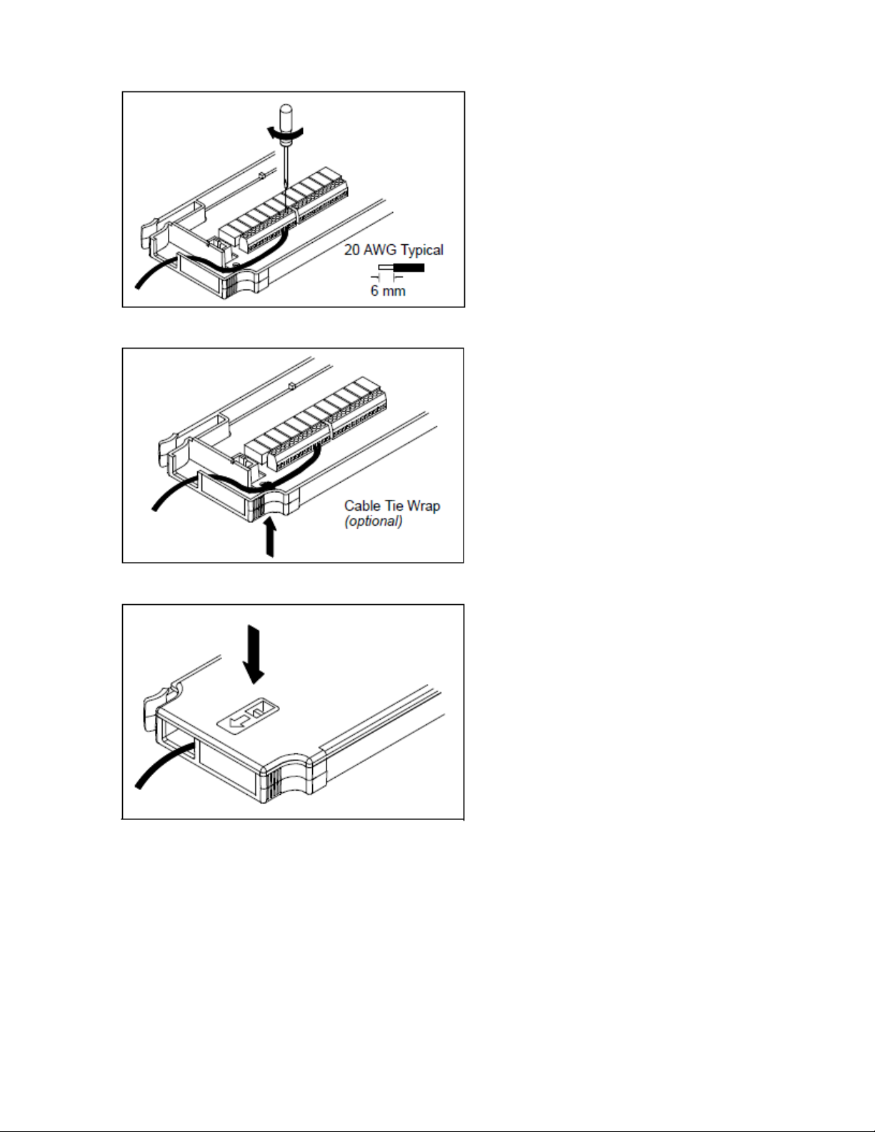
2 Quick Start
2.
Connect the wiring to the screwdriver.
3.
Route the wiring through the strain relief.
4.
Replace the module cover.
40 Keysight DAQ970A User'sGuide
Page 41

5.
Install the module in to the instrument (at the rear panel).
2 Quick Start
Keysight DAQ970A User's Guide 41
Page 42

2 Quick Start
Uninstalling the Module
To unplug or replace any modules, push inward the clip located at rear left side of the module, and then pull
it out from rear panel.
42 Keysight DAQ970A User'sGuide
Page 43

2 Quick Start
Connect Power and I/O Cables
To turn on the instrument
Before powering on the instrument, make sure allsignal sources are turned off. Turn on signal sources after
the instrument is powered on. Turn off signal sources before the instrument is powered off. Connect the
power cord and LAN or USB cable as desired. Press the On/Standby switch on the front panel. Note that
this switch is for standby purpose only. To disconnect the mains from the instrument, remove the power
cord. If the instrument does not turn on, verify that the power cord is firmly connected.
The table below shows the statuses of the LED color displayed while the instrument is powered-on:
LED color Instrument status
LEDoff No ACmains power connected.
LED is amber Instrument is in standby mode with ACmains power connected.
LED is green Instrument is turned on.
Power-on self test
After turning on, the instrument runs a power-on self test and displays a message on how to obtain help,
along with the current IP address.
The front-panel display will light up brieflywhile the instrument perform its power-on self test, with all meas-
urement channels turned off. If the power-on self test fails, the error annunciator, is displayed on the
screen. See "SCPIError Messages" in the DAQ970A Programming Guide for more information on SCPI
error codes and error messages.
A complete self-test performs a more extensive set of tests than those performed at power-on. See
the
DAQ970A Service Guide
The instrument's default measurement function is DC voltage (DCV), with autoranging enabled.
for more informationon the instrument complete self-test procedure.
To turn off the instrument
Press and hold the On/Standby switch for about half a second. This prevents you from accidentally turning
off the instrument by brushing against the power switch.
If you turn off the instrument by disconnecting the power source (this is not recommended), the
instrument turns on as soon as the power is reconnected. You do need to press the
switch again.
On/Standby
Keysight DAQ970A User's Guide 43
Page 44

2 Quick Start
Use the Built-in Help System
The built-in help system provides context-sensitive help on any front panel key or menu softkey. A list of
help topics is also available to help you learn about the instrument. All messages, context-sensitive help,
and help topics appear in the selected language. The menu softkey labels are not translated.
View the list of help topics
Press [Home] > Help > Help Topics to view the list of help topics. Use the knob or the front panel arrow
keys to highlight the desired topic, and press [Select] to view the help contents.
In this example, we selected 1 Get HELP on any key. The following help topic appears:
Press Done to exit the help.
44 Keysight DAQ970A User'sGuide
Page 45

2 Quick Start
View the help information for a front panel key
Press and hold any front panel key or softkey to get context-sensitive help, such as [Scan]. If the message
contains more information than will fit on the display, use the knob or the front panel arrow keys to load in
previous/next page.
Press Done to exit the help.
View the instrument information
Press [Home] > Help > About to view the instrument information such as product serial number, IP address
(when connected to LAN interface), and currently installed firmware revision. Press Done to exit.
Keysight DAQ970A User's Guide 45
Page 46

2 Quick Start
Adjust the Carrying Handle
The carrying handle has three positions (as shown below). To adjust the handle position, grasp the sides of
the handle, pull outward, and rotate the handle.
Bench-top viewing positions Carrying position
46 Keysight DAQ970A User'sGuide
Page 47

2 Quick Start
Rack Mounting the Instrument
You can mount the instrument in a standard 19-inch rack cabinet by ordering the rack mount kit with the
part number provided as below. Instructions and mounting hardware are included with each rack-mounting kit. Any Keysight System II instrument of the same size can be rack-mounted beside the DAQ970A.
To prevent overheating, do not block air flow to or from the instrument. Allow enough clearance at
the rear, sides, and bottom of the instrument to permit adequate internal air flow.
Remove the carrying handle, and the front and rear rubber bumpers, before rack-mounting the instrument.
Removing the handle and bumpers
To remove the handle, rotate it to the vertical position and pull the ends outward.
To remove the front and rear rubber bumpers, stretch a corner and then slide it off.
Rack mounting a single instrument
To rack mount a single instrument, order the adapter kit (part number: DAQA190A-FG).
Keysight DAQ970A User's Guide 47
Page 48

2 Quick Start
Rack mounting instruments side-by-side
To rack mount two instruments side-by-side, order the lock-link kit (part number: DAQA194A-FG) and
flange kit (part number: DAQA191A-FG). Be sure to use the support rails inside the rack cabinet.
48 Keysight DAQ970A User'sGuide
Page 49
2 Quick Start
Keysight BenchVue Data Acquisition (DAQ) Software
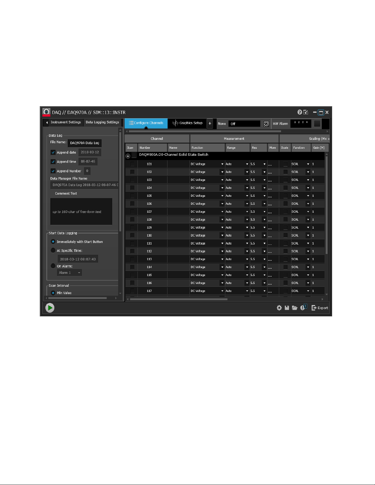
The Keysight BenchVue Data Acquisition (DAQ) Software is a Windows-based application that makes it easy
to use the instrument with your PC for gathering and analyzing measurements. Use this software to set up
your test, acquire and archive measurement data, and perform real-time display and analysis results of your
measurements. The Keysight BenchVue Data Acquisition (DAQ) Software can be downloaded from
www.keysight.com/find/benchvue.
Application main screen:
BenchVue Data Acquisition (DAQ) Software Licensing
To evaluate a BenchVue application for a free 30-day trial period, go to the BenchVue Application view,
click once on the desired application, and then click on the "Start Trial" button – the trial period is based
on the number of calendar days remaining. After the trial period expires, you will be required to purchase
a software license for that application. Keysight's flexible licensing options allow you to select the license
type and license terms that best fit your software needs. For more information on purchasing and
installing a software license, see BenchVue Software Licensing Options in the Keysight BenchVue Data
Acquisition (DAQ) Software Help .
Keysight DAQ970A User's Guide 49
Page 50

Page 51

3 Features and Functions
3 Features and Functions
System Overview
Front Panel Menu Reference
[Scan] Key
[Monitor] Menu
[Home] Menu
[View] Menu
[Channel] Menu
[Interval] Menu
[Math] Menu
[Copy] Menu
[Alarm] Menu
[Utility] Menu
[Module] Menu
[Save Recall] Menu
Web Interface
Module Overview
Keysight DAQ970A User's Guide 51
Page 52

Page 53
3 Features and Functions
System Overview
This section provides an overview of a computer-based system and describes the parts of a data acquisition
system.
Data Acquisition System Overview
Signal Routing and Switching
Measurement Input
Control Output
Data Acquisition System Overview
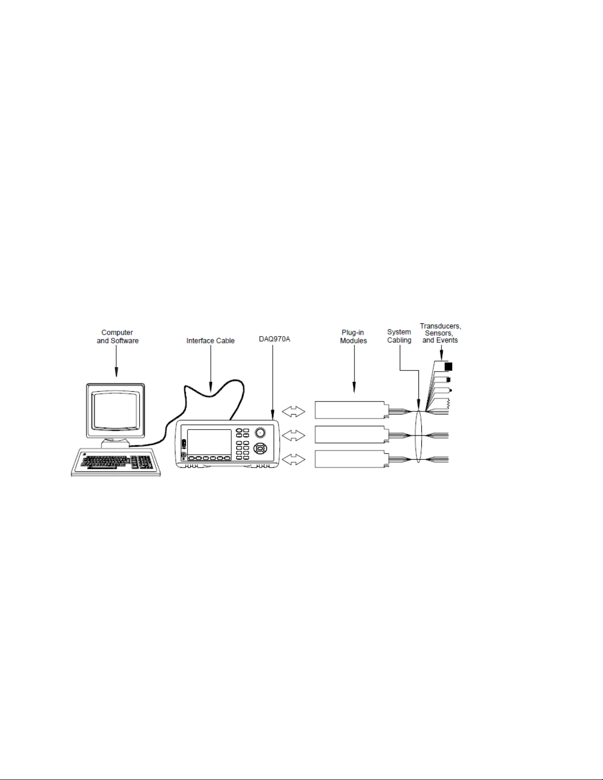
You can use the Keysight DAQ970A as a stand-alone instrument, but there are many applications where
you will want to take advantage of the built-in PC connectivity features. A typical data acquisition system is
shown below:
The configuration offers the following advantages:
l You can use the DAQ970A to perform data storage, data reduction, mathematical calculations, and con-
version to engineering units. You can use the PC to provide easy configuration and data presentation.
l You can remove the analog signals and measurement sensors from the noisy PC environment and elec-
tricallyisolate them from both the PC and earth ground.
l You can get a single PC to monitor multiple instruments and measurement points while performing other
PC-based tasks.
DAQ970A logic circuitry
As shown below, the logic circuitry for the DAQ970A is divided into two sections: earth-referenced and floating. These two sections are isolated from each other in order to maintain measurement accuracy and
repeatability. See Noise Caused by Ground Loops for further details on ground loops.
Keysight DAQ970A User's Guide 53
Page 54
3 Features and Functions
The earth-referenced and floating circuitry communicate with each other via an optically-isolated data link.
The earth-referenced section communicates with the floating section to provide PC connectivity. The
DAQ970A is shipped with LAN and USBinterfaces connectivity.
The earth-referenced section also provides four hardware alarm outputs and external trigger lines. You can
use the alarm output lines to trigger external alarm lights, sirens, or send a TTL-compatible pulse to your
control system.
The floating section contains the main system processor and controls all of the basic functionality of the
instrument. This is where the instrument communicates with the plug-in modules, scans the keyboard, controls the front-panel display, and controls the internal DMM. The floating sections also performs measurement scaling, monitors alarm conditions, converts transducer measurements to engineering units, time
stamps scanned measurements, and saves data in non-volatile memory.
Plug-in modules
The DAQ970A offers a complete selection of plug-in modules to give you high-quality measurement, switching, and control capabilities. The plug-in modules communicate with the floating logic via the internal isolated digital bus. The multiplexer modules also connect to the internal DMMvia the internal analog bus.
Each modules has its own microprocessor to offload the mainframe processor and minimize backplane
communications for faster throughput. See Module Overview for more information.
Module number Common uses
Measurement input
DAQM900A Scanning and direct measurement of temperature, voltage, resistance, frequency, and current
DAQM901A
(DAQM901A only) by using the internal DMM.
DAQM902A
DAQM907A Digital Input, Event Counting.
DAQM908A Scanning and direct measurement of temperature, voltage, and resistance by using the internal DMM.
Signal routing
54 Keysight DAQ970A User'sGuide
Page 55

3 Features and Functions
Module number Common uses
DAQM900A N/A
DAQM901A Multiplexing of signals to or from external instruments.
DAQM902A N/A
DAQM904A 32 Crosspoint Matrix Switching.
DAQM905A 50 Ω high-frequency applications (<2 GHz).
DAQM908A N/A
Control output
DAQM903A General-purpose switching and control using Form C (SPDT) switches.
DAQM907A Digital Output, Voltage (DAC) Outputs.
System cabling
The plug-in modules have screw-terminal connectors to make it easy to connect your system cabling. The
type of cabling that you use to connect your signals, transducers, and sensors to the module is critical to
measurement success. Some types of transducers, such as thermocouples, have very specific requirements
for the type of cable that can be used to make connections. Be sure to consider the usage environment
when choosing wire gauge and insulation qualities. Wire insulation typically consists of materials such as
PVC or PTFE. Table below lists several common cable types and describes their typicaluses.
Wiring insulation and usage is described in more detail in "System Cabling and Con-
nections".
Cable type Common uses Comments
Thermocouple Extension Wire Thermocouple measurements. Available in specific thermocouple types. Also avail-
able in shielded cable for added noise immunity.
Twisted Pair, Shielded Twisted
Pair
Shielded Coaxial, Double-Shielded Coaxial
Flat Ribbon, Twisted pair Ribbon
Measurement inputs, voltage outputs,
switching, counting.
VHF signal switching. Most common cable for high-frequency signal rout-
Digital Input/Output Often used with mass termination connectors. These
Most common cable for low-frequency measurement
inputs. Twisted pair reduces common mode noise.
Shielded-twisted pair provides additional noise
immunity.
ing. Available in specific impedance values (50 Ω or
75 Ω). Provides excellent noise immunity. Doubleshielded cable improves isolation between channels.
Requires special connectors.
cables provide little noise immunity.
Transducers and sensors
Transducers and sensors convert a physical quantity into an electrical quantity. The electrical quantity is
measured and the result is then converted to engineering units. For example, when measuring a thermocouple, the instrument measures a DC voltage and mathematically converts it to a corresponding temperature in °C, °F, or K.
Keysight DAQ970A User's Guide 55
Page 56

3 Features and Functions
Measurement Typical transducer types Typical transducer output
Temperature Thermocouple 0 mV to 80 mV
RTD 2-wire or 4-wire resistance from 5 Ω to 500 Ω
Thermistor 2-wire resistance from 10 Ω to 1MΩ
Pressure Solid State ±10 DVC
Flow Rotary Type
Thermal Type
Strain Resistive Elements 4-wire resistance from 10 Ω to 10 kΩ
Events Limit Switches
Optical Counters
Rotary Encoder
Digital System Status TTL-compatible Levels
4 mA to 20 mA
0 V or 5 V Pulse Train
Alarm limits
The DAQ970A has four alarm outputs which you can configure to alert you when a reading exceeds specified limits on a channel during a scan. You can assign a high limit, low limit, or both to any configured
channel in the scan list. You can assign multiple channels to any of the four available alarms (numbered 1
through 4). For example, you can configure the instrument to generate an alarm on Alarm 1 when a limit is
exceeded on any of the channels 103, 205, or 320.
You can also assign alarms to channels on the multifunction module. For example, generate an alarm when
a specific bit pattern or bit pattern change is detected on a digital input channel or when a specific count is
reached on a totalizer channel. With the multifunction module, the channels do not have to be part of the
scan list to generate an alarm.
Signal Routing and Switching
The switching capabilities of the plug-in modules available with the DAQ970A provide test system flexibility
and expandability. You can use the switching plug-in modules to route signals to and from your test system
or multiplex signals to the internal DMM or external instruments.
Relays are electromechanical devices which are subject to wear-out failure modes. The life of a relay, or the
number of actual operations before failure, is dependent upon how it is used - applied load, switching frequency, and environment. The DAQ970A relay maintenance system automatically counts the cycles of each
relayin the instrument and stores the total count in non-volatile memory on each switch module. Use this
feature to track relay failures and to predict system maintenance requirements.
Switching topologies
Several switching plug-in modules are available with different topologies for various applications:
Switching topologies Plug-in modules
Multiplexer DAQM900A, DAQM901A, DAQM902A, DAQM905A, DAQM908A
Matrix DAQM904A
Form C (single pole, double throw) DAQM903A
The following sections describe each of these switching topologies.
56 Keysight DAQ970A User'sGuide
Page 57
3 Features and Functions
Multiplexer switching
Multiplexers allow you to connect one of multiple channels to a common channel, one at a time. A simple
4-to-1 multiplexer is shown below. When you combine a multiplexer with a measurement device, like the
internal DMM, you create a scanner. For more information on scanning, see "Scanning".
Multiplexers are available in several types:
Multiplexer type Common use
One-wire (single-ended) For common LO measurements. For more information, see
tiplexers"
Two-wire For floating measurements. For more information, see
Four-wire For resistance and RTD measurements. For more information, see
Multiplexers"
RF Signal Very High Frequency (VHF) for switching frequencies up to 2.8 GHz. For more information, see
"RF Signal Multiplexing"
Matrix switching
.
.
.
"One-Wire (Single-Ended) Mul-
"Two-Wire Multiplexers"
.
"Four-Wire
A matrix switch connects multiple inputs to multiple outputs and therefore offers more switching flexibility
than a multiplexer. Use a matrix for switching low-frequency (less than 10 MHz) signals only. A matrix is
arranged in rows and columns. For example, a simple 3×3 matrix could be used to connect three sources to
three test points as shown below:
Keysight DAQ970A User's Guide 57
Page 58

3 Features and Functions
Any one of the signal sources can be connected to any one of the test inputs. Be aware that with a matrix, it
is possible to make sure that dangerous or unwanted conditions are not created by these connections.
Form C (SPDT) switching
The DAQM903A contains 20 Form C switches (also called single-pole, double-throw). You can use Form C
switches to route signals but they are typically used to control external devices.
Measurement Input
The DAQ970A allows you to combine a DMM(either internal or external) with multiplexer channels to create a scan. During a scan, the instrument connects the DMM to the configured multiplexer channels one at
a time and makes a measurement on each channel.
Any channel that can be "read" by the instrument can also be included in a scan. This includes any combination of temperature, voltage, resistance, current, frequency, or period measurements on multiplexer
channels. A scan can also include a read of a digital port, a read via the sense channel, or a read of the totalizer count on the multifunction module.
58 Keysight DAQ970A User'sGuide
Page 59

3 Features and Functions
The internal DMM
A transducer or sensor converts a physicalquantity being measured into an electrical signal which can be
measured by the internal DMM. To make these measurements, the internal DMM incorporates the following functions:
l Temperature (thermocouple, RTD, and thermistor)
l Voltage (DCand AC up to 300 V)
l Resistance (2-wire and 4-wire up to 1GΩ)
l Current (DC and AC up to 1 A)
l Frequency and Period (up to 300 kHz)
The internal DMM provides a universal input front-end for measuring a variety of transducer types without
the need for additional external signal conditioning. The internal DMM includes signal conditioning, amplification (or attenuation), and a high resolution (up to 22 bits) analog-to-digital converter. A simplified diagram of the internal DMM is shown below:
Signal conditioning, ranging, and amplification
Analog input signals are multiplexed into the internal DMM's signal-conditioning section - typically comprising switching, ranging, and amplification circuitry. If the input signal is a DC voltage, the signal conditioner is composed of an attenuator for the higher input voltages and a DC amplifier for the lower input
voltages. If the input signal is an AC voltage, a converter is used to convert the AC signal to its equivalent DC
value (true RMS value). Resistance measurements are performed by supplying a known DC current to an
unknown resistance and measuring the DCvoltage drop across the resistor. The input signal switching and
ranging circuitry, together with the amplifier circuitry, convert the input to a DC voltage which is within the
measuring range of the internal DMM's analog-to-digital converter (ADC).
You can allow the instrument to automatically select the measurement range using autoranging or you can
select a fixed measurement range using manual ranging. Autoranging is convenient because the instrument automaticallyselects the range to use for each measurement based on the input signal. For fastest
scanning operation, use manual ranging for each measurement (some additional time is required for autoranging since the instrument has to make a range selection.
Analog-to-digital conversion (ADC)
The ADC takes a prescaled DC voltage from the signal-conditioning circuitry and converts it to digital data
for output and display on the front panel. The ADC governs some of the most basic measurement
Keysight DAQ970A User's Guide 59
Page 60

3 Features and Functions
characteristics. These include measurement resolution, reading speed, and the ability to reject spurious
noise. There are severalanalog-to-digital conversion techniques but they can be divided into two types:
integrating and non-integrating. The integrating techniques measure the average input value over a
defined time interval, thus rejecting many noise sources. The non-integrating techniques sample the
instantaneous value of the input, plus noise, during a very short interval. The internal DMMuses an integrating ADCtechnique.
Main processor
The main processor, located in the floating logic section, controls the input signal conditioning, ranging,
and the ADC. The main processor accepts commands from, and sends measurement results to, the earthreferenced logic section. The main processor synchronizes measurements during scanning and control
operations. The main processor uses a multi-tasking operation system to manage the various system
resources and demands.
The main processor also calibrates measurement results, performs Mx+B scaling, monitors alarm conditions, converts transducer measurements to engineering units, time stamps scanned measurements,
and stores data in non-volatile memory.
Scanning
The instrument allows you to combine a DMM (either internal or external) with multiplexer channels to create a scan. During a scan, the instrument connects the DMM to the configured multiplexer channels one at
a time and makes a measurement on each channel.
Before you can initiate a scan, you must set up a scan list to include all desired multiplexer or digital channels. Channels which are not in the scan list are skipped from the scan. The instrument automatically
scans the list of channels in ascending order from slot 1 through slot 3. Measurements are taken only during a scan and only on those channels which are included in the scan list.
You can store up to 100,000 readings in non-volatile memory during a scan. Readings are stored only during a scan and all readings are automatically time stamped. Each time you start a new scan, the instrument clears all readings stored in memory from the previous scan. Therefore, all readings currently stored
in memory are from the most recent scan.
You can configure the event or action that controls the onset of each sweep through the scan list (a sweep
is one pass through the scan list):
You can set the instrument's internal timer to automatically scan at a specific interval as shown below. You
can also program a time delay between channels in the scan list.
60 Keysight DAQ970A User'sGuide
Page 61

3 Features and Functions
You can manually control a scan by repeatedly pressing [Scan] from the front panel.
You can start a scan by sending a software command from the remote interface.
You can start a scan when an external TTL-compatible trigger pulse is received.
You can start a scan when an alarm condition is logged on the channel being monitored.
Scanning with external instruments
You can use the DAQ970A for signal routing or control applications. If you install a multiplexer plug-in
module, you can use the DAQ970A for scanning with an external instrument. You can connect an external
instrument (such as a DMM) to the multiplexer COM terminal.
To control scanning with an external instrument, two control lines are provided. When the DAQ970A and
the external instrument are properly configured, you can synchronize a scan sequence between the two.
Keysight DAQ970A User's Guide 61
Page 62

3 Features and Functions
The multifunction module
The multifunction module (DAQM907A) adds two additional measurement input capabilities to the system: digital input and event totalize.
The multifunction module also contains a dual voltage output (DAC). For more details, see "Transducers
and Sensors".
Digital input
The multifunction module has two non-isolated 8-bit input/output ports which you can use for reading
digital patterns. You can read the live status of the bits on the port or you can configure a scan to include a
digital read. Each port has a separate channel number on the module and contains 8-bits. You can combine the two ports to read a 16-bit word.
62 Keysight DAQ970A User'sGuide
Page 63

3 Features and Functions
Totalizer
The multifunction module has a 26-bit totalizer which can count pulses at a 100 kHz rate. You can manually read the totalizer count or you can configure a scan to read the count.
You can configure the totalizer to count on the rising edge or falling edge of the input signal.
The maximum count is 67,108,863 (226-1). The count rolls over to "0" after reaching the maximum
allowed value.
You can configure the totalizer to read without affecting the count or reset the count to zero without losing any counts.
Control Output
In addition to signal routing and measurement, you can also use the DAQ970A to provide simple control
outputs. For example, you can control external high-power relays using the actuator module or a digital
output channel.
Keysight DAQ970A User's Guide 63
Page 64

3 Features and Functions
The multifunction module
The multifunction module (DAQM907A) adds two additional control output capabilities to the system:
digital output and voltage (DAC) output.
The multifunction module also contains digital input and event totalizer capabilities. For more details, see
"The Multifunction Module".
Digital output
The multifunction module has two non-isolated 8-bit input / output ports which you can use to output
digital patterns. Each port hasa separate channel number on the module and contains 8-bits. You can
combine the two ports to output a 16-bit word.
Voltage (DAC) output
The multifunction module has two analog outputs capable of outputting calibrated voltages between ±12
V with 18 bits of resolution. Each DAC (Digital-to-Analog Converter) channel can be used as a programmable voltage source for analog input control of other devices. A simplified diagram isshown below:
64 Keysight DAQ970A User'sGuide
Page 65
3 Features and Functions
You can set the output voltage to any value between ±12 VDC, in 100 µV steps. Each DAC is earth referenced, it cannot float. Each DAC channel is capable of supplying 15 mA maximum current during output
voltage mode. Or you can set the DAC to constant current mode, to output any current between ±24 mA,
in 0.2 µA steps.
Each DAC channel is capable of supplying 24 mA maximum current.
You must limit the output current to 40 mA for each slot (two DAC channels).
The actuator/general purpose switch
You can think of the DAQM903A Actuator as a control output because it is often used to control external
power devices. The actuator provides 20 independent, isolated Form C (SPDT) switches.
Each channel can switch up to 300 V DC or AC rms. Each switch can also switch up to 1 A DCor AC rms up
to maximum 50 W. For example, the maximum current that you can switch at 120 V is 0.45 A as shown
below:
For control applications, the actuator has the following advantages:
Keysight DAQ970A User's Guide 65
Page 66

3 Features and Functions
Higher voltage and power rating than the digital output channels. The actuator switches can also be used
to control power devices.
When used with high-power devices, however, it is critical that you provide protection to the switch from
capacitive and inductive loads to ensure maximum relay life.
For more information on attenuators, see Using Attenuators.
66 Keysight DAQ970A User'sGuide
Page 67

Front Panel Menu Reference
Table below summarizes the front panel keys and the menu structure.
Key Description
l Initiates/stops a scan, or performs a single sweep in manual trigger mode.
l Press once to initiate a scan; press and hold to stop a scan.
l The key's backlight is turned on while scanning is in progress.
l The instrument automatically scans the configured channels in consecutive order from slot 1 through
slot 3. Channels that are not in the scan list are skipped during the sweep.
l Monitors a channel's measurement data that is useful for troubleshooting the instrument and
observing an important signal.
l You can select to view the monitor measurements in number, bar meter, trend chart, and histogram
format.
l The key's backlight is turned on while monitoring is enabled. The monitor annunciator will also be dis-
played, and the sample annunciator will flash when monitor measurements are made.
l To stop the monitoring mode and return to Home menu page, press this key again on the Monitor
menu page.
l Measures the offset on strain channels.
l Configures the four alarm output hardware lines.
l Displays the instrument information and a list of help topic in selected local language.
l Configures various user preferences.
3 Features and Functions
l Views scanned memoryreadings.
l Views alarm queue.
l Views error queue.
l Views number of relay cycles.
l Channel labeling.
l Closes or opens switches on switching channels.
l Selects measurement function.
l Selects measurement range or autorange.
l Selects the integration time.
l Configures advanced measurement features.
l Configures what starts each sweep, or the interval between sweeps, and the number of sweeps in
the scan.
l Configures the measurement scaling (mX+b, %, dBm, or dB) on the current channel.
l Copies the measurement configuration from the selected channel(s) to other channel(s).
l Configures alarm on the selected channel. There are four configurable alarms in this instrument.
l Self-test.
l Calibration.
l Autocalibration.
l Instrument security (NISPOM).
l Firmware update.
Keysight DAQ970A User's Guide 67
Page 68

3 Features and Functions
Key Description
l Overview of the scan list for the module.
l Performs a module reset.
l Module labeling.
l Saves and recalls instrument state files (.sta extension) and preference files (.prf extension).
l File management.
l Saves the readings from trend chart or histogram.
l Captures and saves the screen image.
l Instrument factory reset and system preset.
l Data logging to a USB drive on the front panel.
l Returns the instrument into local control when the instrument is in remote.
68 Keysight DAQ970A User'sGuide
Page 69

3 Features and Functions
[Scan] Key
Press the [Scan] key on the front panel to initiate or stop a scan, or to perform a single sweep when manual
trigger mode is selected.
Press[Scan] once to initiate a scan.
The instrument automatically scans the configured channels in consecutive order from slot 1 through slot
3. Channels that are not in the scan list are skipped during the sweep. The [Scan] key's backlight is turned
on while scanning isin progress.
Press and hold [Scan] for more than 2 seconds to stop the scan. "Scan stopped" is shown when the scanning is terminated.
Press [Module] > Scan List to view the available channels on the module that are included in the scan list.
See [Module] Menu for more information on the Scan List softkey. See the [Channel] Menu for more
information on how to include a channel in the scan list (using the InScan softkey). Also, see the
[Interval]Menu for more information on how the [Scan] key is used when the manual trigger mode is selec-
ted.
Keysight DAQ970A User's Guide 69
Page 70
3 Features and Functions
[Monitor] Menu
During scanning, you can monitor the measurement data on a selected channel by pressing the [Monitor]
key. The key's backlight is turned on while monitoring is enabled. The monitor annunciator will also be displayed, and the sample annunciator will flash when monitor measurements are made.
You can view the monitor data for all channels in the scan list, except for computed channels (channels 401
through 420). Monitoring of computed channels is only available while scanning and will only display the
reading from the most recent sweep. You can also view monitor data on the DAQM907A digital I/O and
totalizer channels even if they are not in the scan list.
Monitor measurements are made repetitively when scanning is idle or between sweeps of a scan. To stop
the monitoring mode and return to the Home menu page, press the [Monitor] key again on the Monitor
menu page.
In the Monitor menu page, press Display to select the display mode as shown below:
Number
Bar Meter
Trend Chart
Histogram
Number
Displays readings as a number.
Press Peak to enable (On) or disable (Off) the measurement of the Minimum, Maximum, and Peak to Peak
values acquired within the measurement aperture. When enabled, Clear Peaks softkey will display. Press
70 Keysight DAQ970A User'sGuide
Page 71
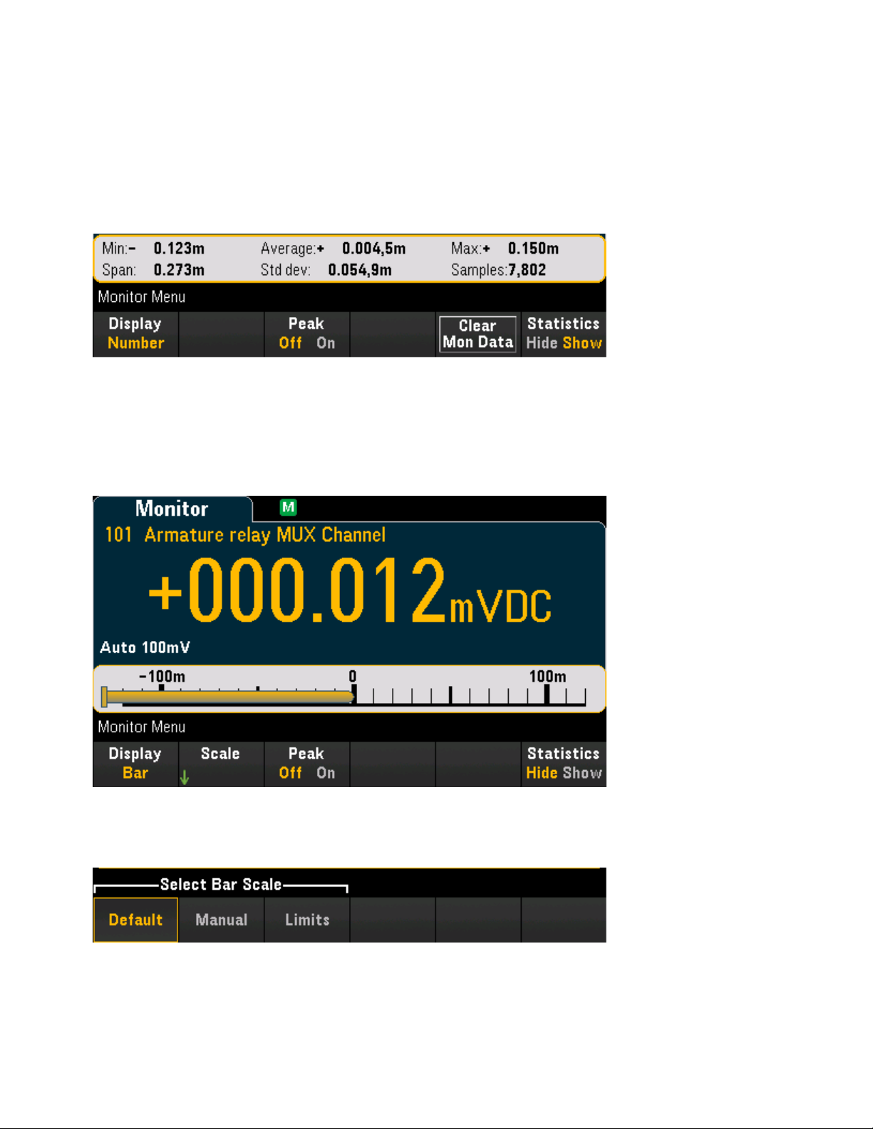
3 Features and Functions
this softkey to reset the reading of peak values by clearing the accumulated history of peak-to-peak function. This setting is also applicable to Bar Meter.
Press Statistics to select Hide or Show the measurement statistics for the monitor channel. Monitor channel statistics are cleared when monitor mode is turned on, when the monitor channel changes, or when the
monitor channel's configuration is changed. Press Clear Mon Data softkey to clear the statistics, trend
chart, and histogram on the monitor channel. This setting is also applicable to Bar Meter, Trend Chart, and
Histogram.
Bar Meter
The bar meter adds a moving bar below the standard Number display.
The Peak and Statistics softkeys behave as they do in Number display.
The Scale softkey specifies how the meter scale is determined.
Keysight DAQ970A User's Guide 71
Page 72
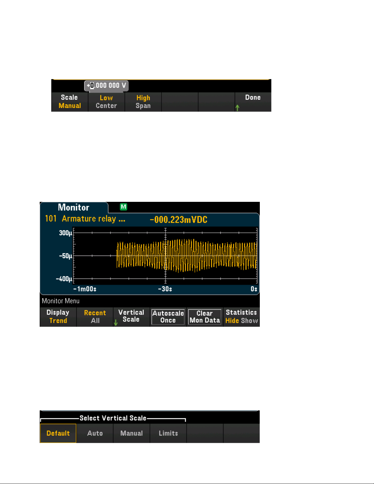
3 Features and Functions
a. Default sets the scale to the measurement range.
b. Manual allows you to configures the scale either as High and Low values or as a Span around a Center
value. For example, a scale that goes from a Low of -500 Ω to a High of 1000 Ω could also be specified
as a Center of 250 Ω with a Span of 1500 Ω.
c. Limits set the scale to the alarm limits. Note that this softkey is only available when you configure alarm
on the selected channel by pressing the [Alarm] key on the front panel.
Trend Chart
In the Continuous measurement mode, the trend chart shows data trends over time. Data is collected and
displayed in pixel columns as described below:
The Statistics softkey behave as in Number display.
The Recent/All softkey specifies whether all measurements (All) or only the most recent measurements
(Recent) are shown on the trend chart. Neither selection clears reading memory. In All mode, the trend
chart displays all readings being taken and builds from left to right. After the display is filled, the data
becomes compressed on the left side of the display as new data is added on the right side of the display. In
Recent mode, the trend chart displays data taken during a specified amount of time.
The Vertical Scale softkey specifies how the current vertical scale is determined.
72 Keysight DAQ970A User'sGuide
Page 73
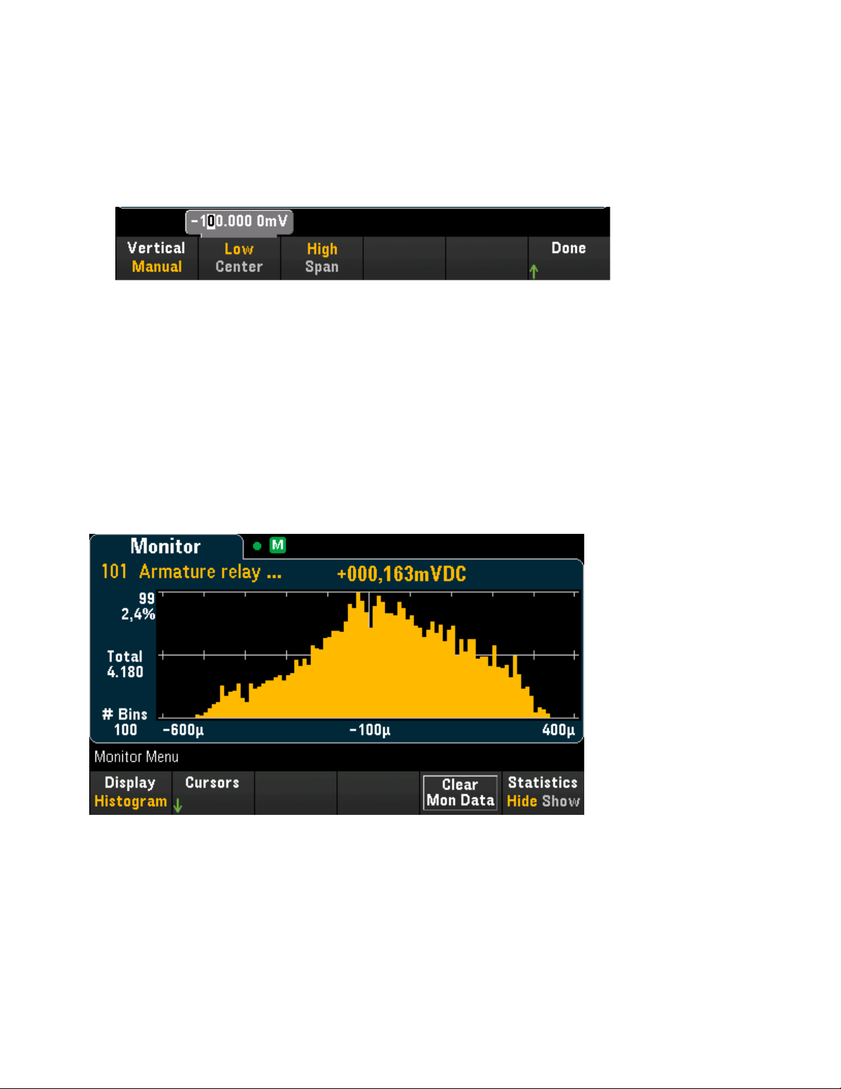
3 Features and Functions
a. Default sets the scale to the measurement range.
b. Auto automatically adjusts the scale to appropriatelyfit the line currently shown on the screen.
c. Manual allows you to configure the scale either as High and Low values or as a Span around a Center
value. For example, a scale from a Low of 0 V to a High of 5 V is equivalent to a Center of 2.5 V and a
Span of 5 V.
d. Limits set the scale to the alarm limits. Note that this softkey is only available when you configure alarm
on the selected channel by pressing the [Alarm] key on the front panel.
Press Autoscale Once softkey to automatically scale the trend chart's vertical axis one time based on the
scanned memory readings shown on the screen. This also sets the vertical scale mode to Manual.
Histogram
The histogram shows measurement data as a graphical representation of the distribution of measurement
data. Data is grouped in bins represented by vertical bars in the histogram display.
The Statistics softkey behave as in Number display.
Press the Cursors softkey to display the histogram cursors. Cursors in the histogram are specified as bin
numbers and display the range of values covered by those bins, the count and the percentage of the total.
The total count and percentage of total, as well as the measurement range covered, between the cursor
bins, are also displayed.
In the graphic below, cursor B1 (violet vertical lines) is positioned on bin number 30 and cursor B2 (green
vertical lines) is positioned on bin number 50 (bin number shown above the B2 softkey). The bin inform-
Keysight DAQ970A User's Guide 73
Page 74

3 Features and Functions
ation for cursor B1 is shown in the violet box, the bin information for B2 in the green box. For example, the
information in the B1 box is in the graphic below is:
l
0.310m to 0.300m - Range of DCV measurement values for this bin.
l
#153 - Number of samples in this bin.
l
0.698% - Percentage of the total number of samples in this bin.
The data between the B1 and B2 cursors, including the data in the B1 and B2 bins, is shown to the right of
the violet and green boxes. In the graphic above:
l
Span: 0.210m - The measurement range covered from B1 to B2.
l
#6776 - The number of samples from B1 to B2.
l
30.9% - The percentage of the total number of samples from B1 to B2.
74 Keysight DAQ970A User'sGuide
Page 75

3 Features and Functions
[Home] Menu
In the Home menu page, you can see an overview of the current scan operation in a glance: sweep count,
trigger source, next sweep time, scan start date and time, the measurement function of the selected channel, and whether data logging to USB drive is enabled. The instrument will return to this Home menu page
when monitoring mode is stopped.
Measures the offset on strain channels
Configures the four alarm output hardware lines
Display instrument information and help topics
Configures various user preferences
Strain Offset
This softkey is only available after you configured the channel for strain measurements by pressing
[Channel]>Measure
multiplexer modules. See Strain for details.
Strain offset is also known as the unstrained value. You can select one or more channels on which you want
to measure the offset value. The strain formula will automatically use this offset value when calculating the
measurement result.
, and select
STRAIN
with DAQM900A, DAQM901A, DAQM902A, and DAQM908A
Keysight DAQ970A User's Guide 75
Page 76

3 Features and Functions
To configure the strain offset:
1. In Select softkey, use the knob or the front panel arrow keys to enable the strain offset measurement
on the highlighted channel to perform. Currently selected channel is marked with an "X". Press this
softkey again to disable the offset measurement on the highlighted channel. Pressing this softkey will
enable the Measure Now and Clear Offsets softkeys.
2. Press Select All to enable the offset measurement on all listed channels. Press this softkey again to dis-
able the offset measurement on all listed channels.
76 Keysight DAQ970A User'sGuide
Page 77

3 Features and Functions
3. Press Measure Now to immediately measures the offset value on the selected channel(s). Offset read-
ings will display on the screen as shown below:
4. Press Clear Offsets softkey if you would like to immediately clear the strain offset value to 0 on the
selected channel(s).
Alarm Output
Configures the four alarm output hardware lines. Four TTL-compatible alarm outputs are available on the
rear panel Ext Trig/Alarms connector. You can use these hardware outputs to trigger external alarm lights,
sirens, or send a TTL-compatible pulse to your control system. You can assign an alarm to any configured
channel and multiple channels can be assigned to the same alarm number. Each alarm output line represents the logical "OR" of all channels assigned to that alarm number (an alarm on any of the associated
channels willpulse the line).
Clear - Clears the state of a specified alarm output line (alarms 1 through 4).
Clear All - Clears the state of all four alarm output lines.
Mode - Selects the output mode for all four alarm output lines.
a. Latch - The alarm output is asserted when a channel's reading crosses a limit, and remains asserted
until you clear it manually, start a new scan, or cycle power.
b. Track - The alarm output is asserted when a channel's reading crosses a limit, and remains asserted
only while subsequent readings remain outside the limit. When a reading returns within the limits, the
output is automatically cleared.
Keysight DAQ970A User's Guide 77
Page 78

3 Features and Functions
Out Alarm - Configures the level for all four alarm output lines that indicates an alarm, either 0 V (TTL-com-
patible low) or 3.3 V (TTL-compatible high). Press this softkey to control the slope of the pulse from the
alarm output
Help
Displays the instrument information and a list of help topics in the selected local language. See Use the
Built-in Help System for details.
User Settings
Configures user preferences that control how the user interacts with the instrument. These settings are
saved in non-volatile memory and can be saved in a preferences (.prf) file.
I/O
Power On
Display Options
DMM On/Off
Language
Date/Time
Number Format
Sounds
I/O
Configures the I/O parameters for remote operations over the LANand USB interfaces.
SCPIID determines the manufacturer and model number returned by identification query (*IDN? com-
mand). The serial number and version information are unaffected. Use this setting to avoid changing existing test system code where the manufacturer or model number are verified and to maximize backwards
compatibility with the Keysight 34970A and 34972A.
78 Keysight DAQ970A User'sGuide
Page 79

3 Features and Functions
The default settings return "Keysight Technologies" followed by the model number "DAQ970A". For more
information, see the *IDN? and SYSTem:PERSona Subsystem commands in the Keysight DAQ970A Programming Guide.
Important: In order to update the instrument firmware from remote, the model number in the *IDN?
response must match the actual instrument model number. If you have changed the instrument's *IDN?
response to another instrument, when attempting to update the firmware from remote, you will see this
error: The instrument is not supported by this firmware file. To update the firmware, either update using the
front panel procedure or, from remote, use SYSTem:PERSona:MODel to set the *IDN? to match the actual
model number, update the firmware, and then use SYSTem:PERSona:MODel again to set the *IDN?
response to the other model number.
Refer to the links below for the remaining of softkey settings.
l LAN On/Off
l LANSettings
l LANReset
l USBSettings
Power On
Configures the instrument's power-on state and power-on message.
Power On selects the state that is loaded at power-up. This can be either the state when the instrument
was powered down with the power switch (Last), a user-selected state file (User Defined), or the factory
default state (Factory Defaults).
Power On Message sets a message that is displayed when the instrument powers up and when you press
[Home] > Help >About. Use the knob or the front panel arrow keys and [Select] key to select the letters.
Then press Done to exit and save the message. The message will appear as shown below when you turn the
instrument on or press [Home] > Help > About.
Display Options
Display Options configures the display.
Keysight DAQ970A User's Guide 79
Page 80
3 Features and Functions
You can enable or disable the display, adjust the brightness (10 to 100%), pick a color scheme, and enable
or disable the screen saver. If you turn off the display, press any front panel key to turn it on again. By
default, the screen saver increases display life by dimming the display during long periods of inactivity. You
may disable this screen saver from the front panel only. The displayis enabled when power is cycled, after an
instrument reset (*RST), or when you return to local (front panel) operation. Press the [Local] key ([Save
Recall] key) to return to the local state.
DMM On/Off
Enables or disables the internal DMM. annunciator will display when internal DMMis disabled.
Language
Selects the local language for front panel use.
All messages, context-sensitive help, and help topics appear in the selected language. The menu softkey
labels are not translated.
Date/Time
Sets the date and time of the real-time clock in 24-hour format. The real-time clock does not automatically
adjust for time zone changes or daylight savings time. Be sure to set the date and time when you first
receive your instrument. Use the knob or the front panel arrow keys to set the year, month, day, hour, and
minute.
Number Format
Number Format specifies how numbers are displayed on the front panel: 12,345.6 or 12.345,6. Other pos-
sibilities also exist. For example, you can use the space as a separator.
Sounds
80 Keysight DAQ970A User'sGuide
Page 81

3 Features and Functions
Enables or disables the tone heard associated when an error is generated from the front panel or remote
interface (Beeper), or the click heard when keys are pressed (Key Click).
Keysight DAQ970A User's Guide 81
Page 82
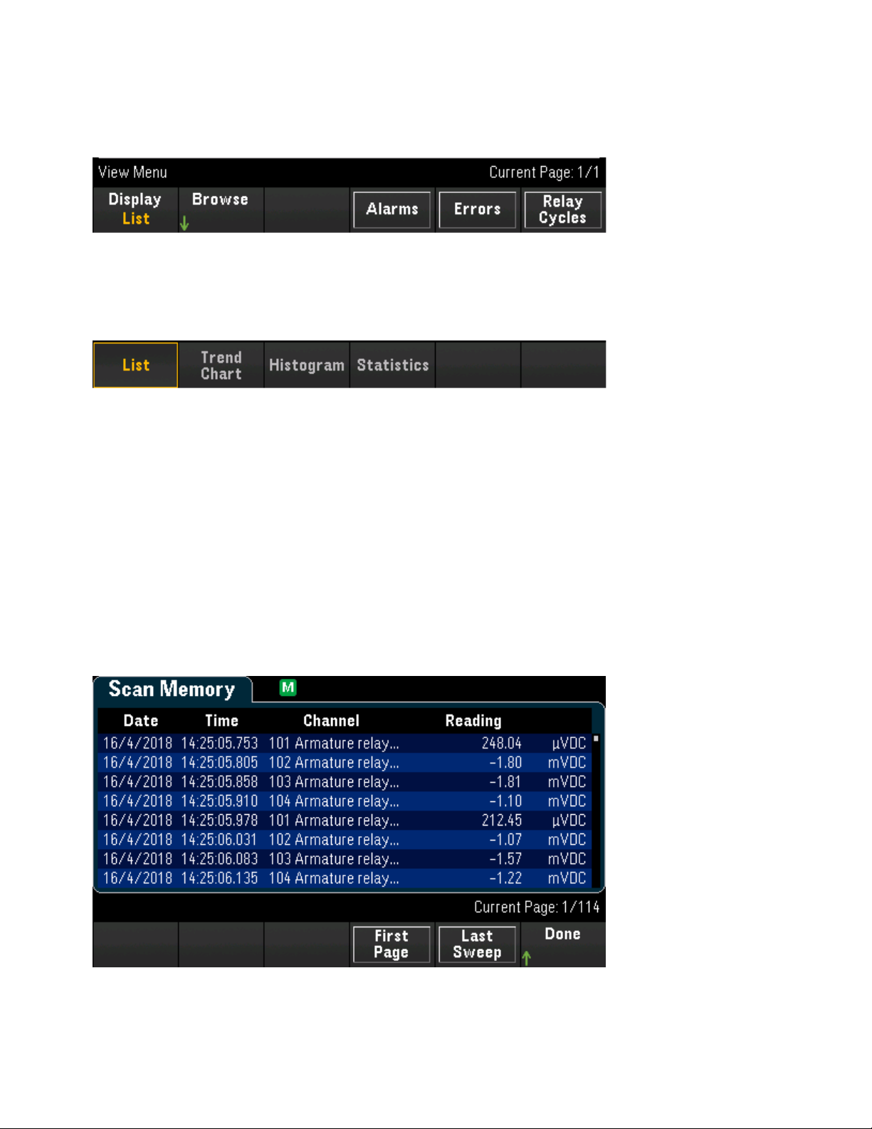
3 Features and Functions
[View] Menu
Press [View] on the front panel to view the scanned memory readings, alarm queue, error queue, and number of relay cycles during scanning or monitoring mode on the selected channel.
Views scanned memory readings (List, Trend Chart, Histogram, Statistics)
In View menu page, press Display to select the display mode as shown below:
List
Trend Chart
Histogram
Statistics
List
Displays the scanned memory readings in list format. Press Browse to display the readings starting from
the beginning of scan (First Page), or starting from the most recent sweep (Last Sweep). Use the knob or
the front panel arrow keys to view the list on subsequent pages; use the right/left arrow keys to move or
return the readings to the last/first page.
Trend Chart
82 Keysight DAQ970A User'sGuide
Page 83
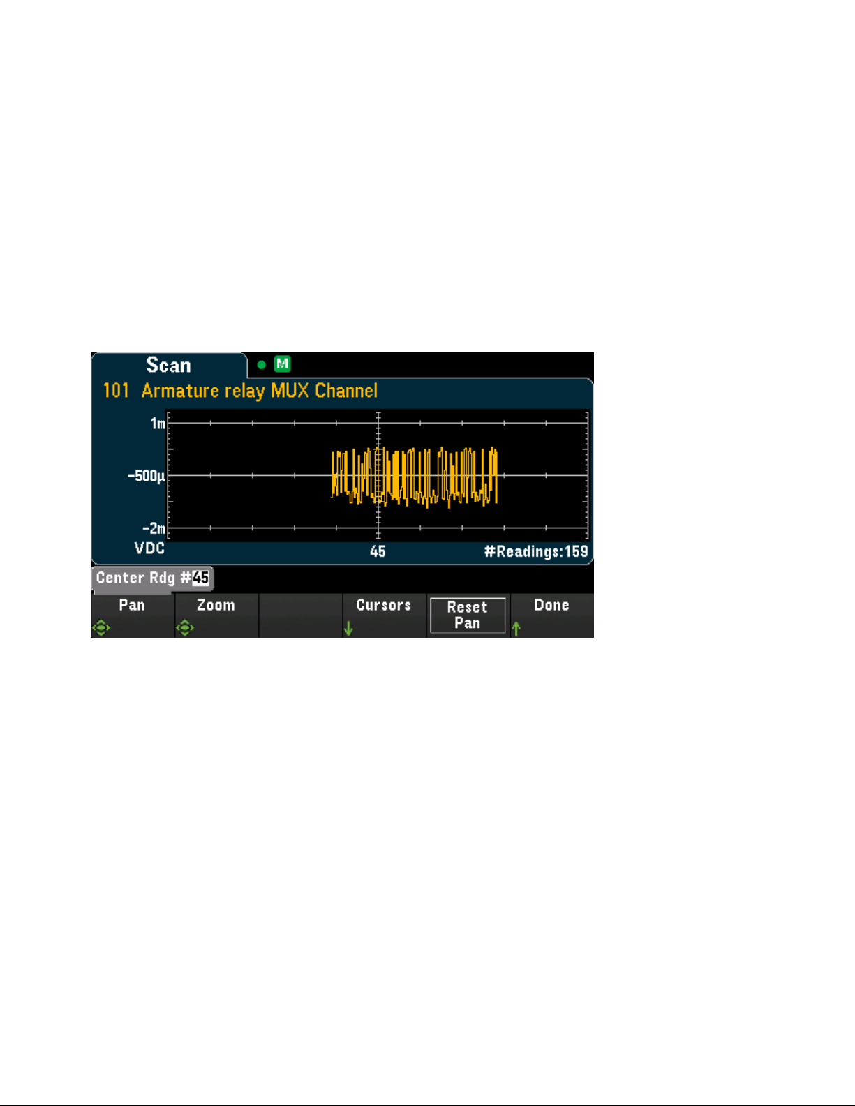
3 Features and Functions
Displays the scanned memory readings in trend chart format. Press Settings to configure the trend chart.
Use the knob or the front panel arrow keys to view the settings on different configured channels. The Ver-
tical Scale and Autoscale Once softkeys behave as they do in the [Monitor] > Display > Trend Chart dis-
play.
Press Advanced to display the advanced settings:
Pan - Selects which reading in memory is displayed at the center of the screen. Use the knob or the
up/right arrow key to increase the reading number displayed which causes the graph data to move to the
left. Use the knob or the down/left arrow key to decrease the reading number displayed which causes the
graph data to move to the right.
Press and release an arrow key to move the cursor one display pixel. Hold down an arrow key to move the
cursor in 20-pixel increments. The number of readings represented per pixel depends on the zoom percentage.
Zoom - Sets the horizontal axis zoom percentage. Press Zoom and use the knob or the up/down arrow
keys to select the amount of zoom, in percent. 100% is the maximum amount of zoom with a maximum of
one reading shown per display pixel column. The display is 400 pixels wide. You can select a zoom percentage of 0.02%, 0.05%, 0.1%, 0.2%, 0.5%, 1%, 2%, 5%, 10%, 20%, 50%, 100%, 200%, 500%, or
1000%.
Tip: Zoom to 1000% to pan one reading at a time. After selecting a reading, you can then decrease the
zoom, if necessary, to view the surrounding signal.
Cursors - Display and control X1, X2, Y1, Y2, and tracking cursors (shown as lines) on the trend chart.
X cursors are vertical lines along the sample or time axis. Use the up or right arrow key to move the cursor
to the right; the down or left arrow key to move the cursor to the left. Press and release an arrow key to
move the cursor one display pixel. Hold down an arrow key to move the cursor in 10 pixel increments. Y
cursors are horizontal lines along the measurement (magnitude) axis in units of the selected measurement
(DCV or DCI). Use the left and or right arrow keys to select a digit of magnitude displayed above the Y1 or
Y2 softkey. You can then use the up or down arrows keys to increment/decrement the digit and move the
cursor up or down by that amount. Cursor X1 and Y1 are violet; cursor X2 and Y2 are green.
Press Cursors > Cursors to display the choices:
Keysight DAQ970A User's Guide 83
Page 84
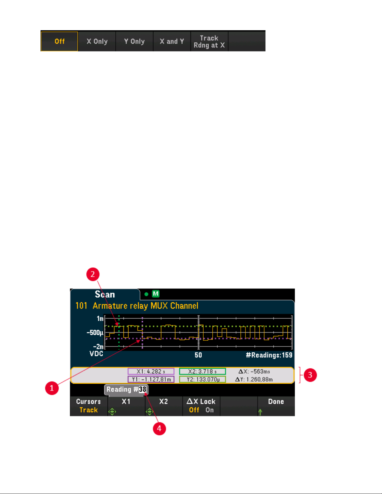
3 Features and Functions
Off - Disables the cursors displayed.
X Only - Displays only the X1 and X2 cursors. In this mode, these softkeys are available:
l
X1 - Use the knob or the front panel arrow keys to control the X1 cursor.
l
X2 - Use the knob or the front panel arrow keys to control the X2 cursor.
l
∆X Lock - When On, keeps the X cursors a fixed distance apart as either cursor is moved.
Y Only - Displays only the Y1 and Y2 cursors. In this mode, these softkeys are available:
l
Y1 - Use the knob or the front panel arrow keys to control the Y1 cursor.
l
Y2 - Use the knob or the front panel arrow keys to control the Y2 cursor.
l
∆Y Lock - When On, keeps the X cursors a fixed distance apart as either cursor is moved.
l
Place Yn on Screen - Press Y1 or Y2 followed by this softkey to set the cursor to a value that
puts it into view on the trend chart.
X and Y - Displays the X1, X2, Y1 and Y2 cursors. In this mode, these softkeys are available:
l
X1 - Use the knob or the front panel arrow keys to control the X1 cursor.
l
X2 - Use the knob or the front panel arrow keys to control the X2 cursor.
l
Y1 - Use the knob or the front panel arrow keys to control the Y1 cursor.
l
Y2 - Use the knob or the front panel arrow keys to control the Y2 cursor.
Track Rdng at X - Select two readings, by reading number, using X1 and X2 softkeys to display X (time) and
Y (magnitude) values for each reading, and the delta X and delta Y values.
84 Keysight DAQ970A User'sGuide
Page 85
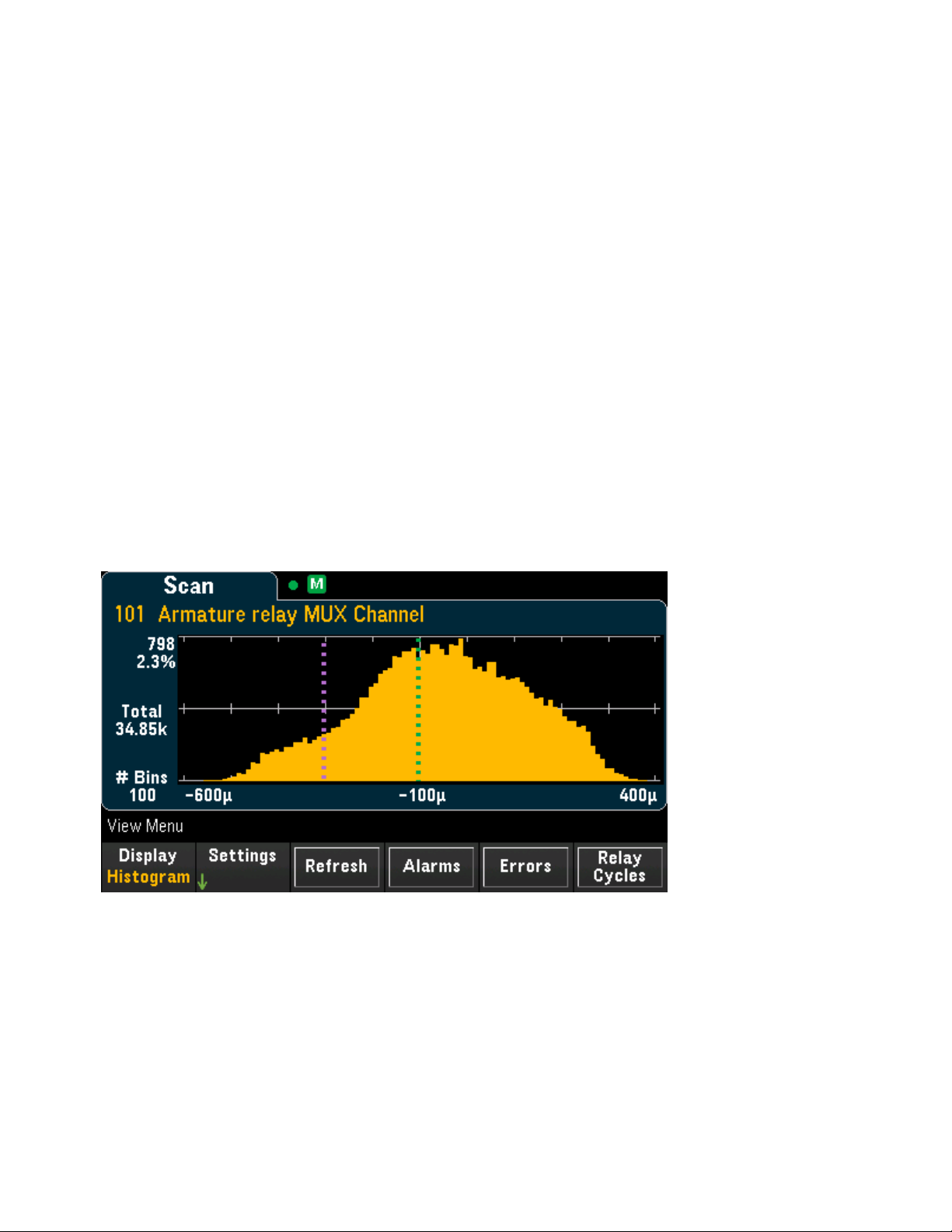
3 Features and Functions
(1) Y1 cursor tracks X1 cursor position.
(2) Y2 cursor tracks X2 cursor position.
(3) Cursor time and amplitude information, ∆X, ∆Y.
(4) Press X1 or X2 to displayreading number.
These softkeys are available for Track Rdng at X mode:
l
X1 - Use the knob or the front panel arrow keys to control the X1 cursor.
l
X2 - Use the knob or the front panel arrow keys to control the X2 cursor.
l
∆X Lock - When On, keeps the X cursors a fixed distance apart as either cursor is moved.
Tip: To record the X and Y data and the delta X and Y data as a screen shot, take a screen shot of the Web
UI, not the front panel screen shot utility.
Press Reset Pan to set the pan (center reading) to "0".
Histogram
Displays the scanned memory readings in histogram format. Press Settings to configure the histogram.
The Cursors softkey behave as it does in the [Monitor] > Display > Histogram display. Press Refresh to recalculate the histogram, including any new readings.
Statistics
Displays the scanned memory readings of a selected channel in statistics format (Maximum, Minimum,
Peak to Peak, Average, and Standard Deviation). Toggle between Statistics to display the per-channel statistics and Pk Times to displaythe time of occurrence of the per-channel minimum and maximum peak readings.
Keysight DAQ970A User's Guide 85
Page 86
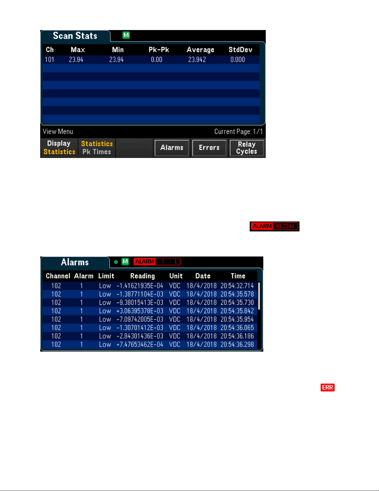
3 Features and Functions
View alarm queue
In View menu page, press Alarms to displaythe first 20 alarms, including the reading and time stamp, in
the alarm queue. You are only able to view this alarm queue when the alarm limit is configured on the selec-
ted channel by pressing [Alarm] key on the front panel. Alarm annunciator, willdisplay as
below. In the following alarm queue, it shows that Alarm 1 with Low limit is configured on the channel 102.
See Alarm Menu for details.
View error queue
In View menu page, press Errors to display up to the 20 errors in the error queue. Error annunciator,
is cleared as you read them.
When the front panel Error annunciator (ERR) turns on, one or more command syntax, execution, or hardware errors have been detected. A record of up to 20 errors is saved in the instrument's error queue.
86 Keysight DAQ970A User'sGuide
Page 87
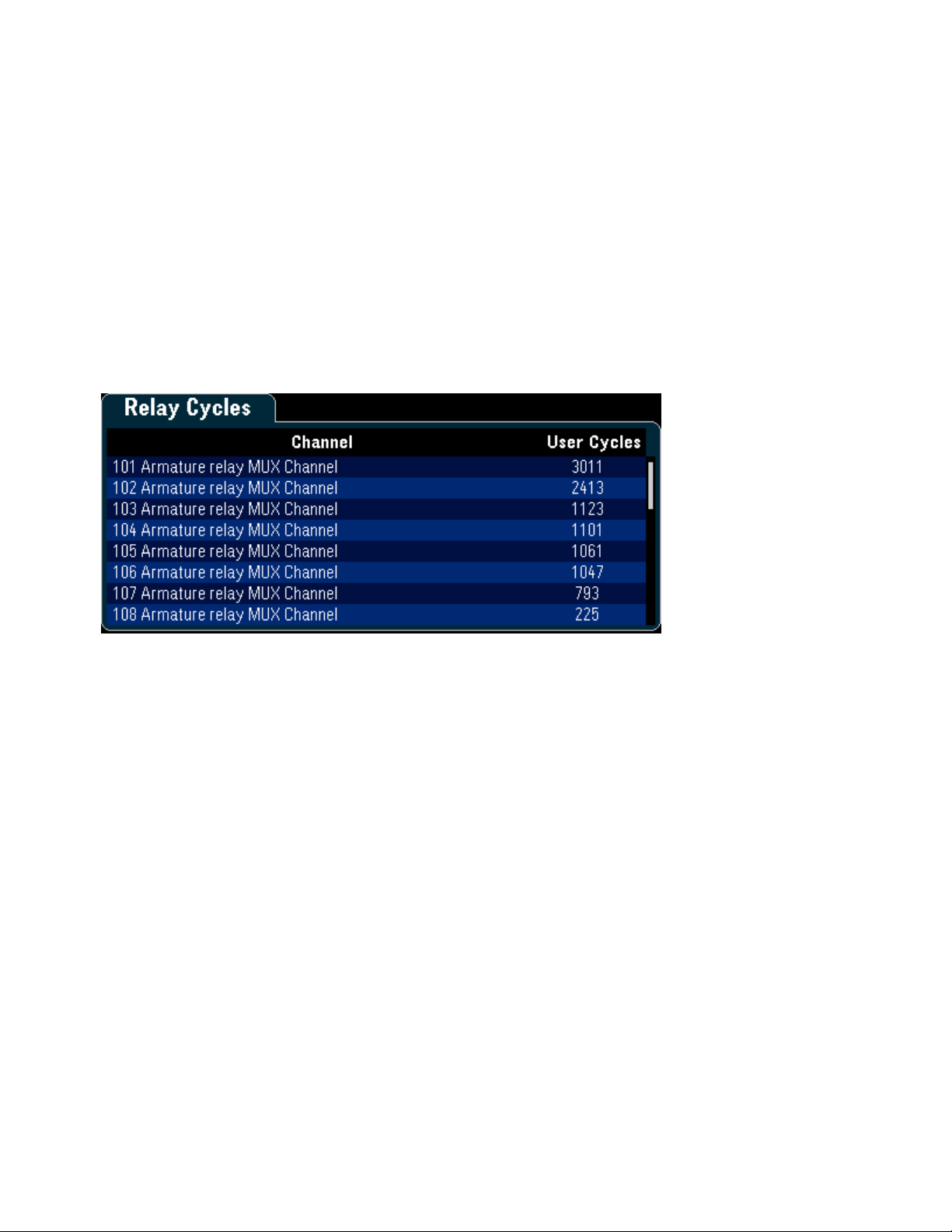
3 Features and Functions
Errors are retrieved in first-in-first-out (FIFO) order. The first error returned is the first error that was saved.
Errors are cleared as you read them. When you have read all errors from the queue, the ERR annunciator
turns off and the errors are cleared. The instrument beeps once each time an error is generated.
If more than 20 errors have occurred, the last error saved in the queue (the most recent error) is replaced
with "Error queue overflow". No additional errors are stored until you remove errors from the queue. If no
errors have occurred when you read the error queue, the instrument responds with "No error".
View number of relay cycles
In View menu page, press Relay Cycles to display the number of cycles for all relays on the selected module. Each module counts the number of closures on each relay and saves the counts in non-volatile
memory on the module. Below image shows the number of cycles for all relays on the DAQM901A multiplexer module.
Keysight DAQ970A User's Guide 87
Page 88

[Channel] Menu Overview
[Channel] Menu Overview
Measurements on Multiplexer Modules
DAQM907A Multifunction Module
Computed Channel
Scanning with External Instruments
Channel Labelling
88 Keysight DAQ970A User'sGuide
Page 89

[Channel] Menu Overview
Measurements on Multiplexer Modules
The Keysight DAQ970A supports many common measurement functions with the multiplexer module.
With any multiplexer module installed on the rear panel, press [Module] and use the knob or the front panel
arrow keys to navigate into the desired multiplexer module.
You can configure the measurement function on the selected channel by pressing [Channel] > Measure.
Selecting Off will disable the measurement function in current selected channel. No any measurement function will be displayed in the scan list on the selected channel. Default measurement function will set to DC
voltage.
Table below shows the overview of each supported multiplexer module on the measurement function. Click
on each link to see the details of each configuration step.
Measurement
function
Temperature - Thermocouple
Temperature - RTD
Temperature - Thermistor
Strain - Bridge
Strain - Direct
DC voltage
AC voltage
DC current
AC current
Resistance
Frequency
Period
Diode
Capacitance
DAQ970A multiplexer module
DAQM900A DAQM901A DAQM902A DAQM908A
√ √ √
√ √ √
√ √ √
√ √ √ √
√ √ √
√ √ √ √
√ √ √ √
[1]
√
[1]
√
√ √ √ √
√ √ √ √
√ √ √ √
√ √ √
√ √ √
[2]
[2]
[2]
[2]
Notes:
[1] Channel 21 and 22 only.
[2] 2-wire measurements only. 4-wire measurements are not supported on DAQM908A multiplexer
module.
Keysight DAQ970A User's Guide 89
Page 90

[Channel] Menu Overview
Temperature
This section describes how to configure the selected channel for temperature measurements from the
front panel. Temperature measurements require a temperature transducer probe. The supported probes
are as below:
Thermocouple
2-wire or 4-wire thermistor
2-wire or 4-wire RTD
Thermocouple
1.
Connect a thermocouple to the module's screw terminals.
2. Press [Channel] > Measure, and select TEMP from the selection menu.
3. Press the Units softkey to specify the temperature measurement units as °C (Celsius), °F (Fahrenheit),
or K (Kelvin). You can mix temperature units on different channels within the instrument and on the
same module.
4. Press Sensor Settings > Sensor, specify the type of transducer probe used as TCouple, and press
Type softkey to select the type of thermocouple. Supported types are J (default), K, E, T, N, R, B, and S.
90 Keysight DAQ970A User'sGuide
Page 91

[Channel] Menu Overview
5. Press Integrate Settings softkey to select whether the measurement integration time will be specified
in terms of Number of Power Line Cycles (NPLC) or directly in seconds (Time). Only 1, 2, 10, 20, 100,
and 200 PLC provide normal mode (line frequency noise) rejection. Selecting 100 PLC provides the best
noise rejection and resolution, but the slowest measurements.
NPLC - Sets the integration time as 0.02, 0.06, 0.2, 1, 2, 10, 20, 100, and 200 Power Line Cycles
(PLC). Only 1 PLC and longer times provide normal mode (line frequency noise) rejection. Selecting 100
or 200 PLC provides the best noise rejection and resolution.
Time - Directly sets the integration time in seconds.
Advanced settings
Press Advanced to configure the advanced settings for the measurement.
Auto Zero - Autozero provides the most accurate measurements, but requires additional measurement
time to perform the zero measurement. With autozero enabled (On), the instrument internally measures
the offset following each measurement. It then subtracts that measurement from the preceding reading.
This prevents offset voltages present on the instrument’s input circuitry from affecting measurement accuracy. With autozero disabled (Off), the instrument measures the offset once and subtracts the offset from all
subsequent measurements. The instrument takes a new offset measurement each time you change the
function, range, or integration time. (There is no autozero setting for 4-wire measurements).
Reference - Thermocouple measurements require a reference junction temperature. You can input a
known fixed reference junction temperature (typicallyused for external reference junctions), use the internally measured temperature on the module as the reference junction temperature, or use the external thermistor or RTD measurement. Selects the reference junction source as Internal, External, or Fixed.
Open Check - Enables (On) or disables (Off) the thermocouple check feature to verify that the ther-
mocouples are properly connected for measurements. When enabled, the instrument performs a resistance measurement with each temperature to check for an open circuit. If one is detected, the result will
be shown as +Overload. If this check is not performed, measurement of an open circuit can produce a
voltage reading near zero resulting in an invalid temperature reading.
Delay - Selects whether the delay between channels in the scan list will be automatically or manuallyselec-
ted. By selecting Auto, instrument will automaticallydetermine the channel delaybased on measurement
function, range, integration time, and AC filter setting. By selecting Time, the specified delay (time in
seconds) is inserted between the relay closure and the actual measurement on each channel, in addition to
any delay that will implicitly occur due to relay settling time.
2-wire and 4-wire thermistor
Keysight DAQ970A User's Guide 91
Page 92

[Channel] Menu Overview
1.
Connect a thermistor to the module's screw terminals.
2-wire thermistor:
4-wire thermistor:
2. Press [Channel] > Measure, and select TEMP from the selection menu.
3. Press the Units softkey to specify the temperature measurement units as °C (Celsius), °F (Fahrenheit),
or K (Kelvin). You can mix temperature units on different channels within the instrument and on the
same module.
4. Press Sensor Settings > Sensor, specify the type of transducer probe used as 2-wire or 4-wire Therm,
and press Type softkey to select the type of thermistor. Supported types are 2.2K, 5K (default), and
10K.
92 Keysight DAQ970A User'sGuide
Page 93

[Channel] Menu Overview
5. Press Use as ref to enable (On) or disable (Off) the currently selected channel to be used as the ref-
erence channel for subsequent thermocouple measurements that specify an external reference source.
6. Press Integrate Settings softkey to select whether the measurement integration time will be specified
in terms of Number of Power Line Cycles (NPLC) or directly in seconds (Time). Only 1, 2, 10, 20, 100,
and 200 PLC provide normal mode (line frequency noise) rejection. Selecting 100 PLC provides the best
noise rejection and resolution, but the slowest measurements.
NPLC - Sets the integration time as 0.02, 0.06, 0.2, 1, 2, 10, 20, 100, and 200 Power Line Cycles
(PLC). Only 1 PLC and longer times provide normal mode (line frequency noise) rejection. Selecting 100
or 200 PLC provides the best noise rejection and resolution.
Time - Directly sets the integration time in seconds.
Advanced settings
Press Advanced to configure the advanced settings for the measurement.
Auto Zero - Autozero provides the most accurate measurements, but requires additional measurement
time to perform the zero measurement. With autozero enabled (On), the instrument internally measures
the offset following each measurement. It then subtracts that measurement from the preceding reading.
This prevents offset voltages present on the instrument’s input circuitry from affecting measurement accuracy. With autozero disabled (Off), the instrument measures the offset once and subtracts the offset from all
subsequent measurements. The instrument takes a new offset measurement each time you change the
function, range, or integration time. (There is no autozero setting for 4-wire measurements).
Low Power - Selects the low-power resistance measurement. This sources less current resulting in lower
power dissipation, and less self-heating, in the resistance under test. Typically, this is about 1/10th the current sourced for the standard resistance measurements. The approximate current sourced for each measurement range is shown at the bottom of the resistance range softkeys, for example: (~ 1 mA).
Delay - Selects whether the delay between channels in the scan list will be automatically or manuallyselec-
ted. By selecting Auto, instrument will automaticallydetermine the channel delaybased on measurement
function, range, integration time, and AC filter setting. By selecting Time, the specified delay (time in
seconds) is inserted between the relay closure and the actual measurement on each channel, in addition to
any delay that will implicitly occur due to relay settling time.
2-wire and 4-wire RTD
1.
Connect an RTD to the module's screw terminals.
2-wire RTD:
Keysight DAQ970A User's Guide 93
Page 94

[Channel] Menu Overview
4-wire RTD:
2. Press [Channel] > Measure, and select TEMP from the selection menu.
3. Press the Units softkey to specify the temperature measurement units as °C (Celsius), °F (Fahrenheit),
or K (Kelvin). You can mix temperature units on different channels within the instrument and on the
same module.
4. Press Sensor Settings > Sensor, specify the type of transducer probe used as 2-wire or 4-wire RTD.
Then, selects the nominal resistance, R0, as PT100 (100 Ω) or PT1000 (1000 Ω). R0is the nominal resistance of a RTD at 0 °C.
5. Press Use as ref to enable (On) or disable (Off) the currently selected channel to be used as the ref-
erence channel for subsequent thermocouple measurements that specify an external reference source.
94 Keysight DAQ970A User'sGuide
Page 95

[Channel] Menu Overview
6. Press Integrate Settings softkey to select whether the measurement integration time will be specified
in terms of Number of Power Line Cycles (NPLC) or directly in seconds (Time). Only 1, 2, 10, 20, 100,
and 200 PLC provide normal mode (line frequency noise) rejection. Selecting 100 PLC provides the best
noise rejection and resolution, but the slowest measurements..
NPLC - Sets the integration time as 0.02, 0.06, 0.2, 1, 2, 10, 20, 100, and 200 Power Line Cycles
(PLC). Only 1 PLC and longer times provide normal mode (line frequency noise) rejection. Selecting 100
or 200 PLC provides the best noise rejection and resolution.
Time - Directly sets the integration time in seconds.
Advanced settings
Press Advanced to configure the advanced settings for the measurement.
Auto Zero - Autozero provides the most accurate measurements, but requires additional measurement
time to perform the zero measurement. With autozero enabled (On), the instrument internally measures
the offset following each measurement. It then subtracts that measurement from the preceding reading.
This prevents offset voltages present on the instrument’s input circuitry from affecting measurement accuracy. With autozero disabled (Off), the instrument measures the offset once and subtracts the offset from all
subsequent measurements. The instrument takes a new offset measurement each time you change the
function, range, or integration time. (There is no autozero setting for 4-wire measurements).
Offset Compensation - Offset compensation removes the effects of small DC voltages in the circuit being
measured. The technique involves taking the difference between two resistance measurements, one with
the current source set to the normal value, and one with the current source set to a lower value.
Low Power - Selects the low-power resistance measurement. This sources less current resulting in lower
power dissipation, and less self-heating, in the resistance under test. Typically, this is about 1/10th the current sourced for the standard resistance measurements. The approximate current sourced for each measurement range is shown at the bottom of the resistance range softkeys, for example: (~ 1 mA).
Delay - Selects whether the delay between channels in the scan list will be automatically or manuallyselec-
ted. By selecting Auto, instrument will automaticallydetermine the channel delaybased on measurement
function, range, integration time, and AC filter setting. By selecting Time, the specified delay (time in
seconds) is inserted between the relay closure and the actual measurement on each channel, in addition to
any delay that will implicitly occur due to relay settling time.
Keysight DAQ970A User's Guide 95
Page 96
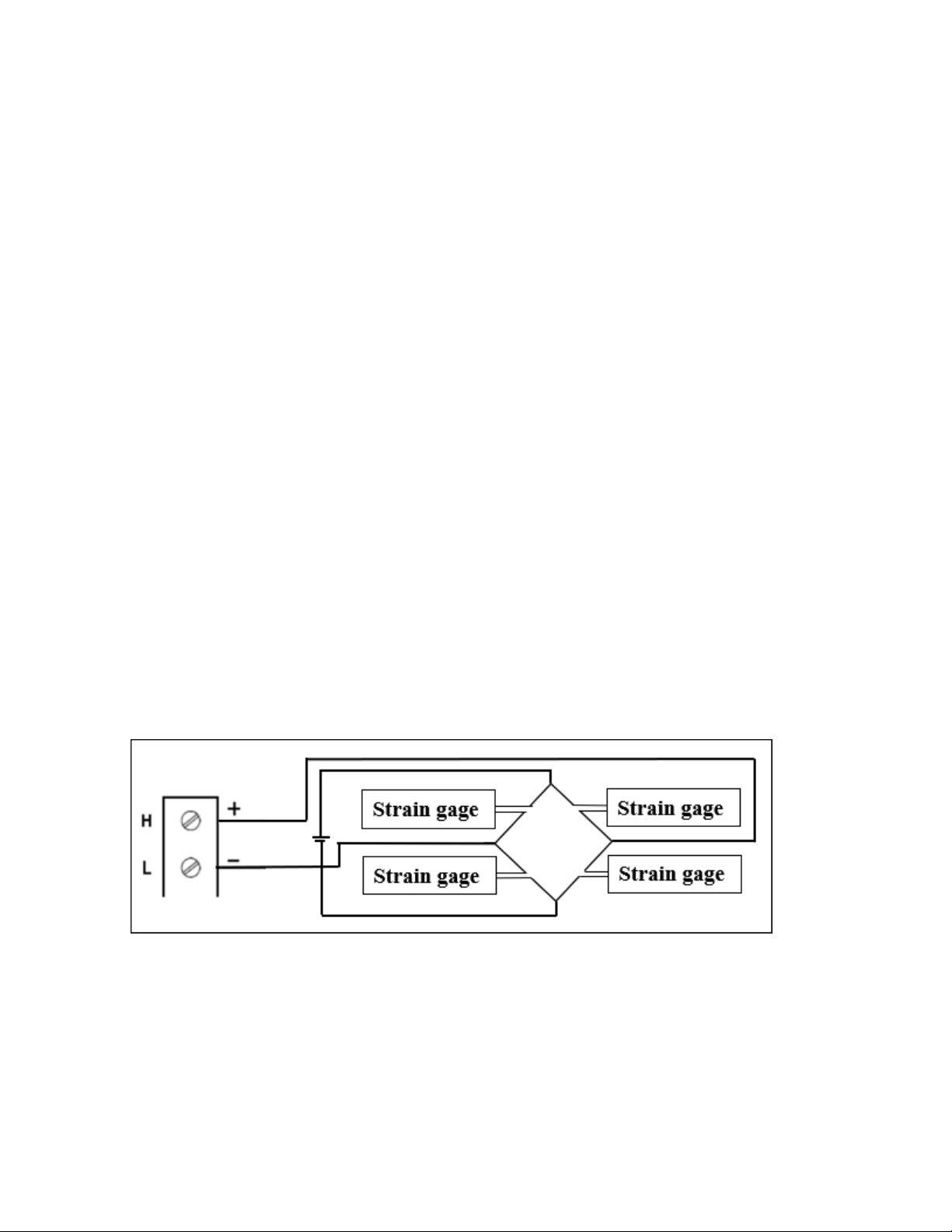
[Channel] Menu Overview
Strain
This section describes how to configure the selected channel for strain measurements from the front panel.
When a force is applied to a body, the body deforms. The deformation per unit length is called strain (ε).
Strain may be either tensile (+) or compressive (-).
The DAQ970A supports two types of strain measurements:
Bridge configuration
Direct resistive method
Once you have configured strain measurement function in all strain channels, press [Home] > Strain Offset
to measure or specify the unstrained offset that will be subtracted from strain measurements before the
strain conversion is performed.
Strain offset
Bridge Configuration
Full and half bridge in bending arrangement
Full and half bridge in Poisson arrangement
Full bridge in bending Poisson arrangement
Quarter bridge arrangement
Full and half bridge in bending arrangement
This section describes how to configure the selected channel for full and half bending bridge strain gage
measurements from the front panel.
1.
Connect bridge configuration source to the module's screw terminals.
Full bending bridge:
Half bending bridge:
96 Keysight DAQ970A User'sGuide
Page 97
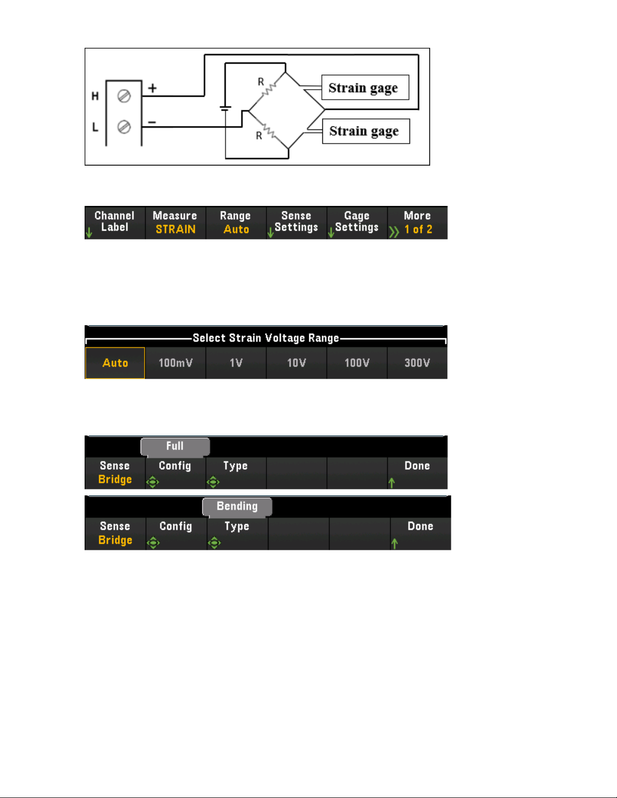
[Channel] Menu Overview
2. Press [Channel] > Measure, and select STRAIN from the selection menu.
3. Press Range and use the knob or the front panel arrow keys to specify the measurement range. Auto
(autorange) automatically selects the range for the measurement based on the input. Autoranging is
convenient, but it results in slower measurements than using a manual range. Autoranging goes up a
range at 120% of the present range, and down a range below 10% of the present range.
4. Press Sense Settings > Sense, specify the strain measurement method as full and half bridge in bend-
ing arrangements.
Keysight DAQ970A User's Guide 97
Page 98
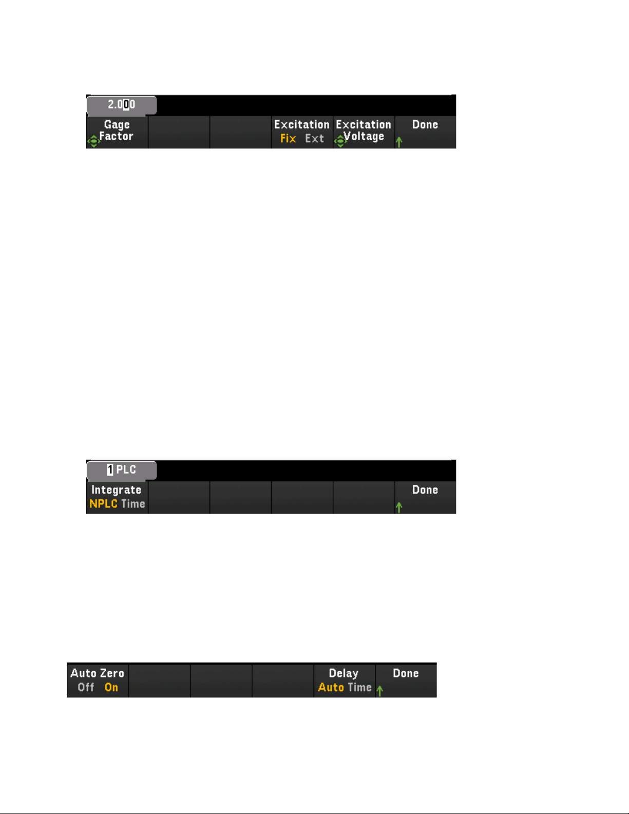
[Channel] Menu Overview
5. Press Gage Settings, and use the knob or the front panel arrow keys to specify various strain gage set-
tings.
Gage Factor - Gage factor is the ratio of the fractional change in resistance to the fractional change in
length (strain) along the axis of the gage. The larger the value, the more sensitive strain gage. Gage
factor is a dimensionless quantity. The typical value is approximately 2.
Strain bridge conversions require the voltage of the external bridge excitation. For this voltage, you can
dedicate a multiplexer channel to measure the excitation voltage, or can specify a known fixed voltage
value. Fixed (Fix) - The fixed value specified by the Excitation Voltage softkey will be used for the strain
conversion. External (Ext) - DCV measurements on the enabled reference channel will be used for subsequent strain bridge measurements that specify an external excitation voltage source. Note that the
external DCV reference channel must be a lower-numbered channel than the strain channel.
Excitation Voltage - Use the knob or the front panel arrow keys to specify the fixed excitation voltage
applied to the bridge by an external voltage source. This value will be used to convert strain bridge measurements on the selected channel.
6. Press Integrate Settings softkey to select whether the measurement integration time will be specified
in terms of Number of Power Line Cycles (NPLC) or directly in seconds (Time). Only 1, 2, 10, 20, 100,
and 200 PLC provide normal mode (line frequency noise) rejection. Selecting 100 PLC provides the best
noise rejection and resolution, but the slowest measurements..
NPLC - Sets the integration time as 0.02, 0.06, 0.2, 1, 2, 10, 20, 100, and 200 Power Line Cycles
(PLC). Only 1 PLC and longer times provide normal mode (line frequency noise) rejection. Selecting 100
or 200 PLC provides the best noise rejection and resolution.
Time - Directly sets the integration time in seconds.
Advanced settings
Press Advanced to configure the advanced settings for the measurement.
Auto Zero - Autozero provides the most accurate measurements, but requires additional measurement
time to perform the zero measurement. With autozero enabled (On), the instrument internally measures
the offset following each measurement. It then subtracts that measurement from the preceding reading.
98 Keysight DAQ970A User'sGuide
Page 99
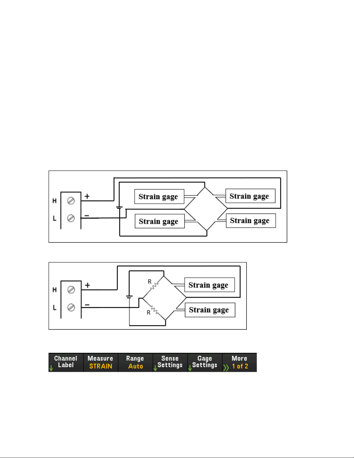
[Channel] Menu Overview
This prevents offset voltages present on the instrument’s input circuitry from affecting measurement accuracy. With autozero disabled (Off), the instrument measures the offset once and subtracts the offset from all
subsequent measurements. The instrument takes a new offset measurement each time you change the
function, range, or integration time. (There is no autozero setting for 4-wire measurements).
Delay - Selects whether the delay between channels in the scan list will be automatically or manuallyselec-
ted. By selecting Auto, instrument will automaticallydetermine the channel delaybased on measurement
function, range, integration time, and AC filter setting. By selecting Time, the specified delay (time in
seconds) is inserted between the relay closure and the actual measurement on each channel, in addition to
any delay that will implicitly occur due to relay settling time.
Full and half bridge in Poisson arrangement
This section describes how to configure the selected channel for full and half Poisson bridge strain gage
measurements from the front panel.
1.
Connect bridge configuration source to the module's screw terminals.
Full bending bridge:
Half bending bridge:
2. Press [Channel] > Measure, and select STRAIN from the selection menu.
Keysight DAQ970A User's Guide 99
Page 100

[Channel] Menu Overview
3. Press Range and use the knob or the front panel arrow keys to specify the measurement range. Auto
(autorange) automatically selects the range for the measurement based on the input. Autoranging is
convenient, but it results in slower measurements than using a manual range. Autoranging goes up a
range at 120% of the present range, and down a range below 10% of the present range.
4. Press Sense Settings > Sense, specify the strain measurement method as full and half bridge in Pois-
son arrangements.
5. Press Gage Settings, and use the knob or the front panel arrow keys to specify various strain gage set-
tings.
Gage Factor - Gage factor is the ratio of the fractional change in resistance to the fractional change in
length (strain) along the axis of the gage. The larger the value, the more sensitive strain gage. Gage
factor is a dimensionless quantity. The typical value is approximately 2.
Poisson Ratio - Specifies the Poisson ratio of the strain gage. Poisson ratio is defined as the negative
ratio of the strain in the transverse direction to the strain in the longitudinal direction.
Strain bridge conversions require the voltage of the external bridge excitation. For this voltage, you can
dedicate a multiplexer channel to measure the excitation voltage, or can specify a known fixed voltage
value. Fixed (Fix) - The fixed value specified by the Excitation Voltage softkey will be used for the strain
conversion. External (Ext) - DCV measurements on the enabled reference channel will be used for subsequent strain bridge measurements that specify an external excitation voltage source. Note that the
external DCV reference channel must be a lower-numbered channel than the strain channel.
Excitation Voltage - Use the knob or the front panel arrow keys to specify the fixed excitation voltage
applied to the bridge by an external voltage source. This value will be used to convert strain bridge measurements on the selected channel.
100 Keysight DAQ970A User'sGuide
 Loading...