

Page 1

Keysight Technologies CX3300 Series
Device Current Waveform Analyzer
CX3322A 2-Channel Model
CX3324A 4-Channel Model
Quick Operation
Guide
Page 2

Warranty
THE MATERIAL CONTAINED IN THIS
DOCUMENT IS PROVIDED “AS IS,”
AND IS SUBJECT TO BEING
CHANGED, WITHOUT NOTICE, IN
FUTURE EDITIONS. FURTHER, TO
THE MAXIMUM EXTENT PERMITTED
BY APPLICABLE LAW, KEYSIGHT
DISCLAIMS ALL WARRANTIES, EITHER EXPRESS OR IMPLIED, WITH
REGARD TO THIS MANUAL AND
ANY INFORMATION CONTAINED
HEREIN, INCLUDING BUT NOT LIMITED TO THE IMPLIED WARRANTIES
OF MERCHANTABILITY AND FITNESS FOR A PARTICULAR PURPOSE. KEYSIGHT SHALL NOT BE
LIABLE FOR ERRORS OR FOR INCIDENTAL OR CONSEQUENTIAL DAMAGES IN CONNECTION WITH THE
FURNISHING, USE, OR PERFORMANCE OF THIS DOCUMENT OR OF
ANY INFORMATION CONTAINED
HEREIN. SHOULD KEYSIGHT AND
THE USER HAVE A SEPARATE
WRITTEN AGREEMENT WITH WARRANTY TERMS COVERING THE MATERIAL IN THIS DOCUMENT THAT
CONFLICT WITH THESE TERMS,
THE WARRANTY TERMS IN THE
SEPARATE AGREEMENT SHALL
CONTROL.
Safety Information
A CAUTION notice denotes a hazard.
It calls attention to an operating
procedure, practice, or the like that,
if not correctly performed or adhered
to, could result in damage to the
product or loss of important data. Do
not proceed beyond a CAUTION
notice until the indicated conditions
are fully understood and met.
A WARNING notice denotes a hazard. It calls attention to an operating
procedure, practice, or the like that,
if not correctly performed or adhered
to, could result in personal injury or
death. Do not proceed beyond a
WARNING notice until the indicated
conditions are fully understood and
met.
U.S. Government
Rights
The Software is “commercial computer
software,” as defined by Federal Acquisition Regulation (“FAR”) 2.101. Pursuant
to FAR 12.212 and 27.405-3 and Department of Defense FAR Supplement
(“DFARS”) 227.7202, the U.S. government acquires commercial computer
software under the same terms by which
the software is customarily provided to
the public. Accordingly, Keysight provides the Software to U.S. government
customers under its standard commercial
license, which is embodied in its End
User License Agreement (EULA), a copy
of which can be found at http://
www.keysight.com/find/sweula. The li-
cense set forth in the EULA represents
the exclusive authority by which the U.S.
government may use, modify, distribute,
or disclose the Software. The EULA and
the license set forth therein, does not
require or permit, among other things,
that Keysight: (1) Furnish technical information related to commercial computer
software or commercial computer software documentation that is not customarily provided to the public; or (2) Relinquish to, or otherwise provide, the government rights in excess of these rights
customarily provided to the public to use,
modify, reproduce, release, perform, display, or disclose commercial computer
software or commercial computer software documentation. No additional government requirements beyond those set
forth in the EULA shall apply, except to
the extent that those terms, rights, or
licenses are explicitly required from all
providers of commercial computer software pursuant to the FAR and the DFARS
and are set forth specifically in writing
elsewhere in the EULA. Keysight shall be
under no obligation to update, revise or
otherwise modify the Software. With
respect to any technical data as defined
by FAR 2.101, pursuant to FAR 12.211
and 27.404.2 and DFARS 227.7102, the
U.S. government acquires no greater
than Limited Rights as defined in FAR
27.401 or DFAR 227.7103-5 (c), as applicable in any technical data.
Notices
Copyright Notice
© Keysight Technologies 2018
No part of this manual may be reproduced in any form or by any means
(including electronic storage and retrieval
or translation into a foreign language)
without prior agreement and written consent from Keysight Technologies as governed by United States and international
copyright laws.
Manual Part Number
CX3300-90300
Edition
Edition 1, June 2018
Published by:
Keysight Technologies International
Japan G.K.
9-1, Takakura-cho, Hachioji-shi, Tokyo
192-0033 Japan
Technology Licenses
The hardware and/or software described
in this document are furnished under a
license and may be used or copied only
in accordance with the terms of such
license.
Declaration of
Conformity
Declarations of Conformity for this product and for other Keysight products may
be downloaded from the Web. Go to
http://www.keysight.com/go/conformity
and click on “Declarations of Conformity.” You can then search by product
number to find the latest Declaration of
Conformity.
CAUTION
WARNING
Page 3

Contents
1. File
• How to save the data
• How to load the data
• What types of data formats are supported on the CX3300 ?
• How to save rarely occurring waveforms automatically
2. Setup
• How to change the horizontal scale and position
• How to change the sampling rate
• How to change the memory depth
• How to change the 14-bit or 16-bit resolution
• How to change the vertical scale and position
• How to change the current range
• How to set the bandwidth limit
• How to minimize the offset current
• How to perform a Skew adjustment
• What determines the effective bandwidth of the instrument ?
• How to zoom in on the waveform
• How to use the waveform memory
• How to overlay multiple acquisitions
• How to display the secondary Y axis
3. Trigger
• How to set the trigger
4. Measure
• How to apply a Measurement Function
• How to apply the A-B marker
• How to place pointers on waveforms
• How to add an Annotation
5. Analyze
• How to apply the post-filter
• How to perform the FFT ( Fast Fourier Transform )
• How to analyze the waveform in the specified area with an Area marker
• How to apply the Power and Current Profiler
• How to apply the XY analysis
6. Utilities
• How to change the measurement units (Clone to Ampere Hour) in Area
analysis
• How to perform User calibration
• How to check the firmware revisions
• How to simulate the 50 MHz or 100 MHz bandwidth option on the
mainframe with the 200 MHz option
• Where to find the Online help
• How to display the menu bar
Page 4
Keysight Technologies
CX3300 Current Waveform Analyzer
Quick Operation Guide
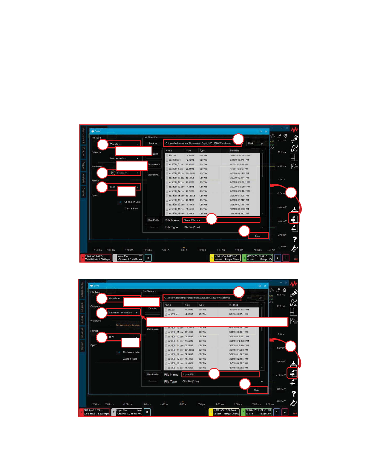
How to save the waveform data
- How to save the Waveform data in CSV format.
- How to save the Waveform FFT data in CSV format.
Save
“Spectrum- Magnitude” or “Spectrum- Phase”
1
2
3
4
5
6
7
Waveform
csv
Save
1
2
3
4
5
6
7
Waveform
csv
Channel 1
4
Page 5
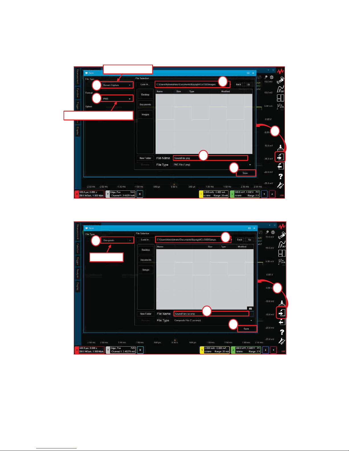
- How to save the Window Image data (Format : PNG / JPEG / Bitmap).
- How to save all setting data and waveform data (File Type : Composite).
Save
1
2
3
4
5
6
Screen Capture
PNG or JPEG or Bitmap
Save
1
2
3
4
5
Composite
Note:
- For further details about the File Type and Format,
please refer to “What types of data formats are supported on the CX3300 ?”.
5
Page 6
Keysight Technologies
CX3300 Current Waveform Analyzer
Quick Operation Guide
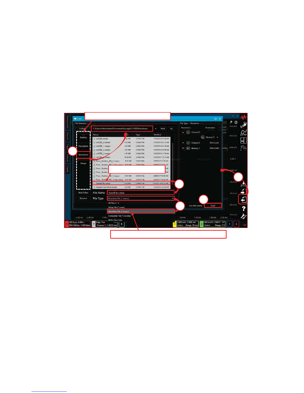
How to load the data
Load
Select one of folders to access
1
2
3
4
5
In this case, select Waveform File (*.cxwav).
SelectedFile.cxwav
Note:
- For further details about the File Type and Format,
please refer to “What types of data formats are supported on the CX3300?”.
6
Page 7
Keysight Technologies
CX3300 Current Waveform Analyzer
Quick Operation Guide
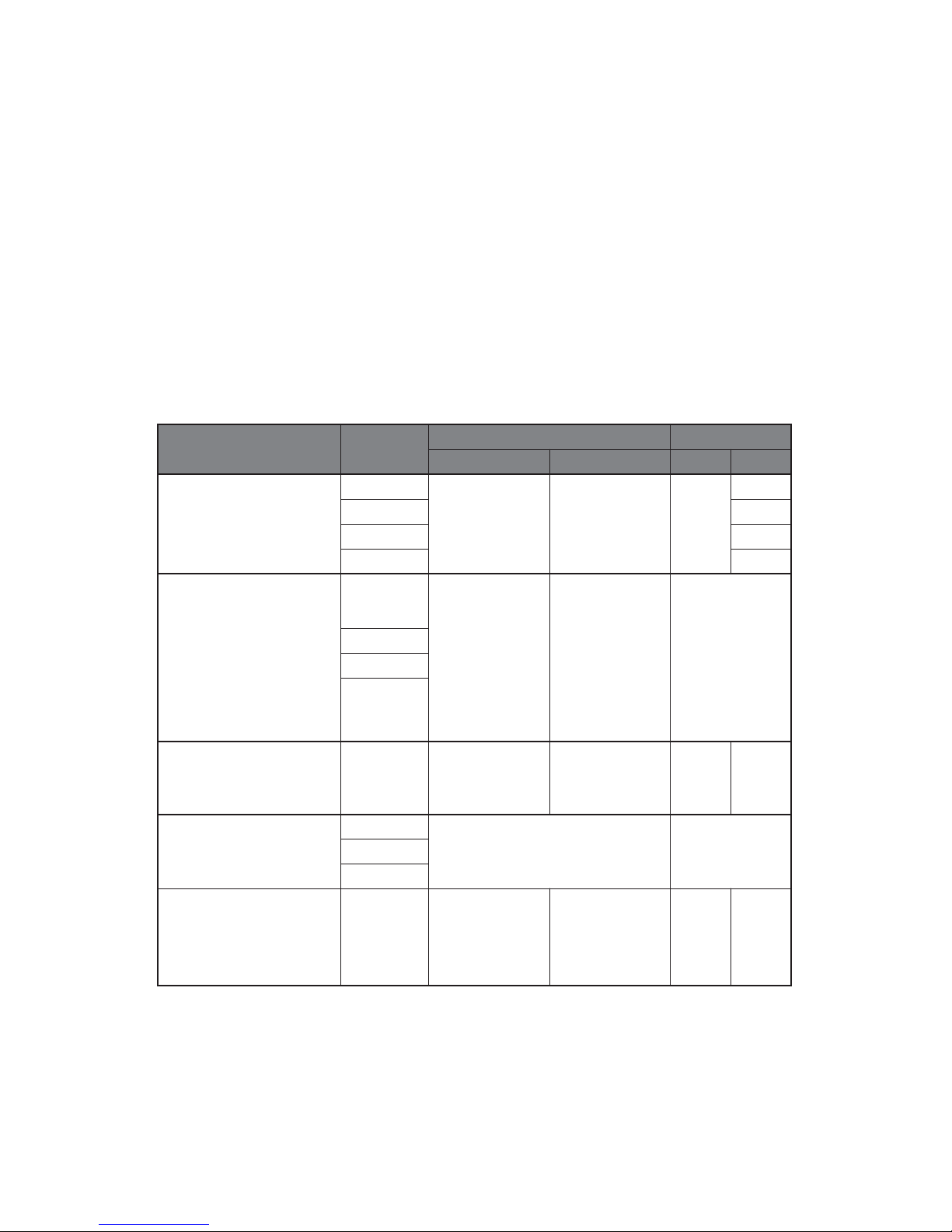
What types of data formats are supported on the CX3300 ?
The CX3300 supports several File Types and Formats when the setup data or
the waveform data is saved or loaded.
File Type Format
Save Load
Setup Data Setup Data
Waveform
(Waveform data)
CSV
No Yes No
No
TSV No
Waveform Yes
HDF5 Yes
Report
(Outputs the
measurement and
analysis result report in
the dedicated style)
XPS
Acquisition
and channel
setups on the
summary bar
Measurement
and analysis
result
No
CSV
TSV
Text
Composite
(All setup data and
waveform data)
- Yes Yes Yes Yes
Screen Capture
(Image of the CX3300
full screen)
PNG
The images on the screen NoJPEG
Bitmap
Setup
(All setup data or
trigger setup data only)
-YesNoYesNo
[ Detail of the File Type and Format ]
7
Page 8
Keysight Technologies
CX3300 Current Waveform Analyzer
Quick Operation Guide
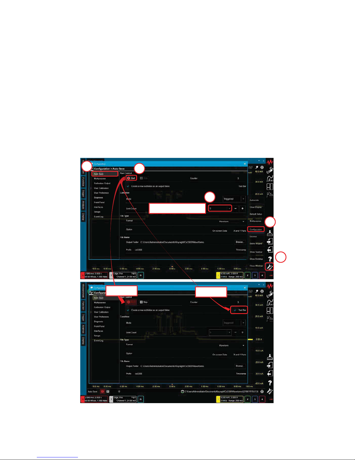
How to save rarely occurring waveforms automatically
1. Select “Utilities > Configuration > Auto Save”.
Utilities
1
2
3
Change Limit Count
4
5
Blinking
Checked
"Auto Save" can be used to automatically save a current waveform if it satisfies
specific conditions.
8
Page 9
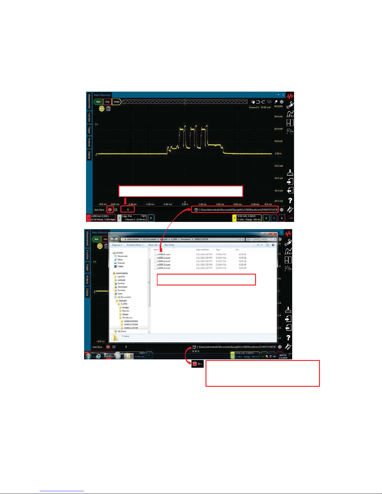
Note:
- During the processing for previously acquired waveforms, the data is not saved
even if the specified condition is satisfied.
- Depending on the File Type and Limit Count, the size or number of the files to
be saved increases.
2. Push the “Auto Save” ( red circle ) button on the lower left of the display.
The waveforms consistent with the trigger condition are stored up until
the Limit Count set on the “Configuration > Auto Save” window.
This number is counted up until the Limit Count.
The 5 files are created in this sample.
The icon shows the disk usage. When the
free space becomes 10% or less, the color
changes from green to red.
9
Page 10
Keysight Technologies
CX3300 Current Waveform Analyzer
Quick Operation Guide
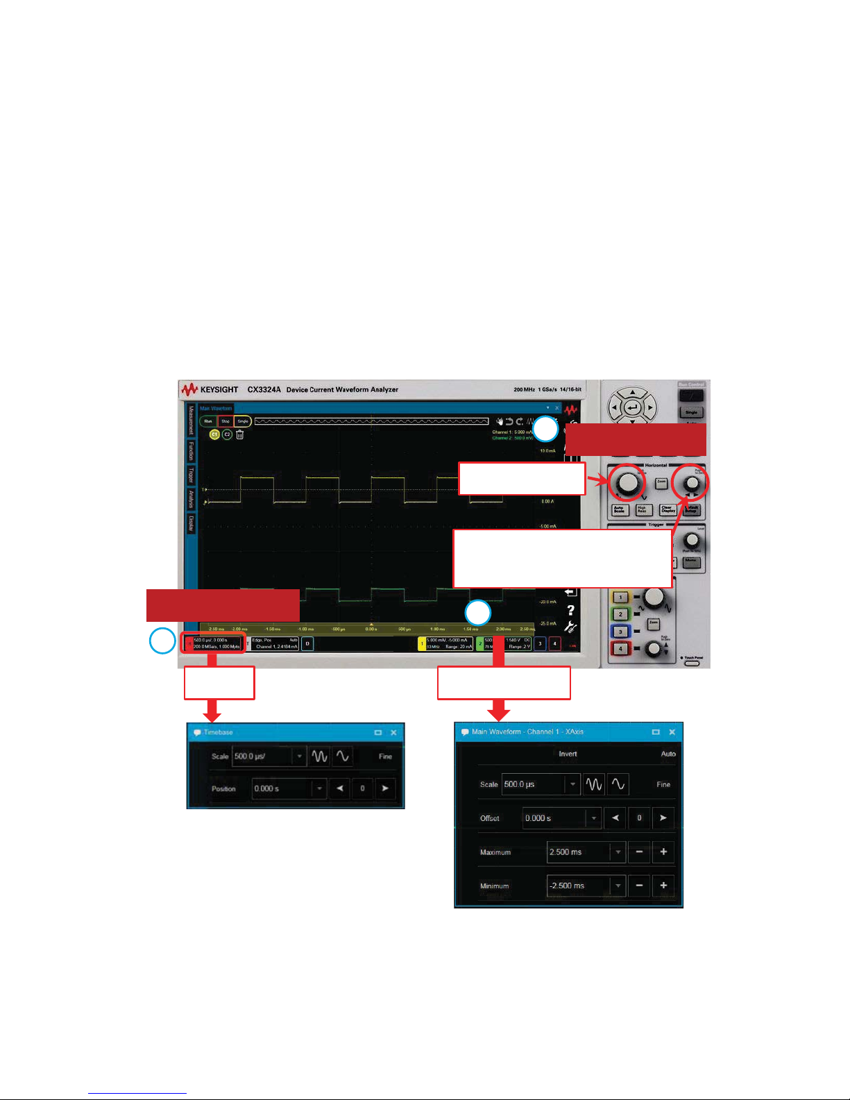
How to change the horizontal scale and position
Horizontal Controls
Change the scale
Change the position. Pressing
it sets zero offset.
Horizontal Summary
a
b
c
You can change the horizontal scale and position using any of the following methods:
a) Using the knobs on the Horizontal Controls
b) Using the Horizontal mini dialog box
c) Using the X Axis dialog box for fine control.
Double-Click
Click
10
Page 11
Keysight Technologies
CX3300 Current Waveform Analyzer
Quick Operation Guide
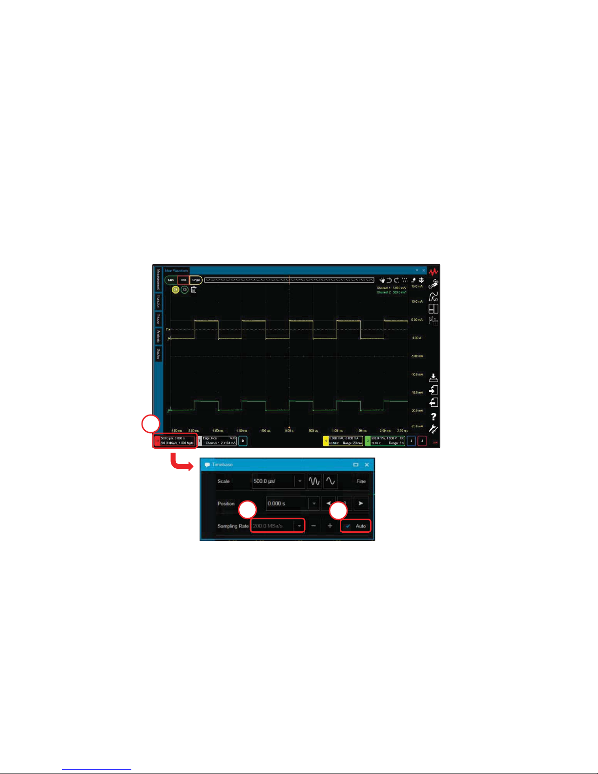
How to change the sampling rate
1. Click on the Horizontal summary to open the Horizontal mini dialog box.
2. Un-check “Automatic”.
3. Set the “Sampling Rate”.
Note:
- If “Auto” is enabled, a suitable sampling rate is selected automatically by the
horizontal scale setting controlled by the Horizontal scale control knob.
1
3
2
11
Page 12
Keysight Technologies
CX3300 Current Waveform Analyzer
Quick Operation Guide
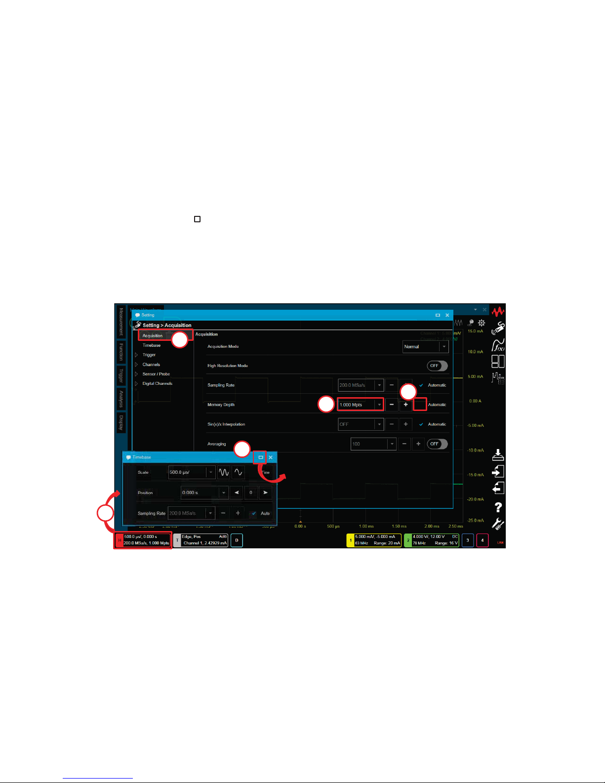
How to change the memory depth
1. Click on “Horizontal summary” to open the “Timebase” mini dialog box.
2. Click on the “ ” at the upper right of the mini dialog box to open
the Setting
dialog box.
3.
Select “Acquisition”.
4. Un-check “Automatic”.
5. Set the “Memory Depth”.
Analysis
3
4
5
Horizontal Summary
1
2
12
Page 13
Keysight Technologies
CX3300 Current Waveform Analyzer
Quick Operation Guide
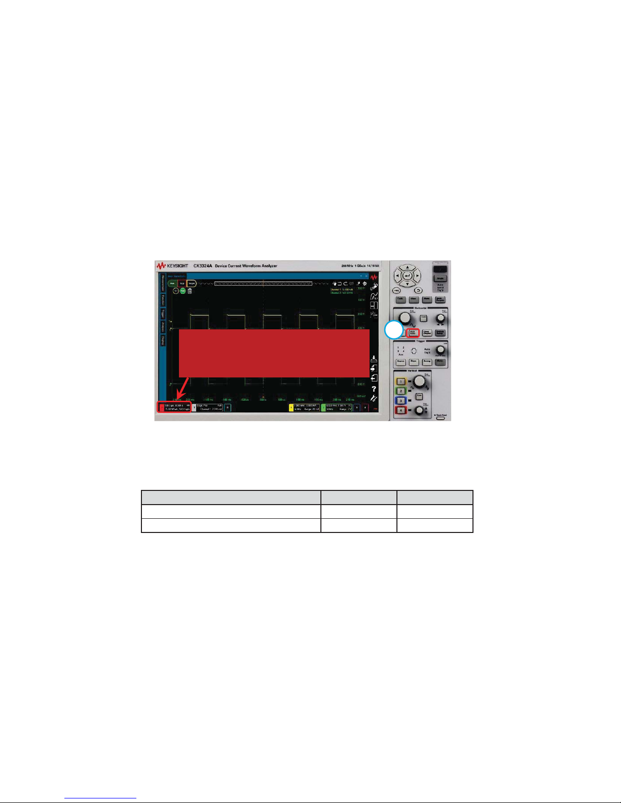
How to change the 14-bit or 16-bit resolution.
a
Change a 14-bit (high speed mode) or a 16-bit (high resolution mode) using the
[High Reso] key.
Indicator on Horizontal Summary
(none) : 14-bit (high speed mode)
“HR” : 16-bit (high resolution mode)
Note:
The maximum sampling rate and bandwidth is automatically changed by the mode.
Resolution Max. Sampling Max. Bandwidth
14-bit (high speed mode) 1 G Sa/s 200 MHz
16-bit (high resolution mode) 75 Msa/s 15 MHz
13
Page 14
Keysight Technologies
CX3300 Current Waveform Analyzer
Quick Operation Guide
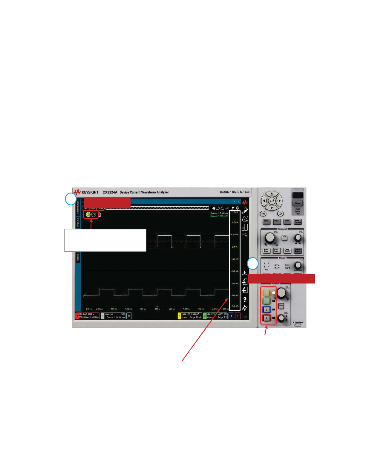
How to change the vertical scale and position
1. How to select the channel.
Select the target waveform by either:
a) Pressing [1], [2], [3] or [4] for the analog input channels
OR
b) Clicking on the icons on the Waveform tray for the analog input
channels or function waveform.
Vertical control keys
Waveform tray
LED shows the selected analog
channel.
The color of the Y axis is the same color as the selected waveform.
The icon for the selected
waveform is highlighted.
b
a
14
Page 15
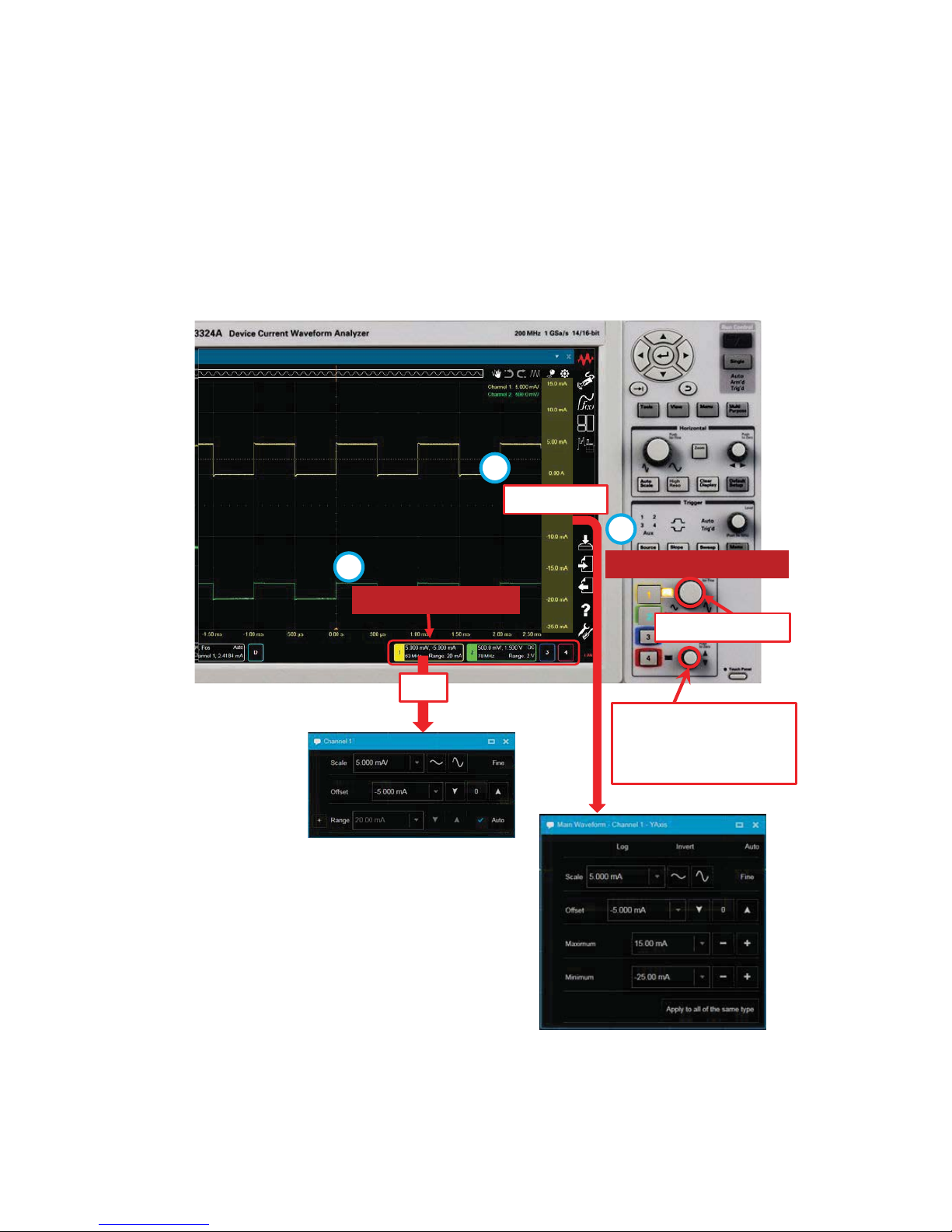
2. How to Change the horizontal scale and position
You can change the horizontal scale and position using any of the
following
methods:
a) Using the knobs on Vertical Controls
b) Using the Vertical mini dialog box
c) Using the Y Axis dialog box for fine control.
Vertical control keys
Change the position.
Pressing it sets zero
offset.
Click
Channel summary
a
b
Double-Click
c
Change the scale
15
Page 16
Keysight Technologies
CX3300 Current Waveform Analyzer
Quick Operation Guide
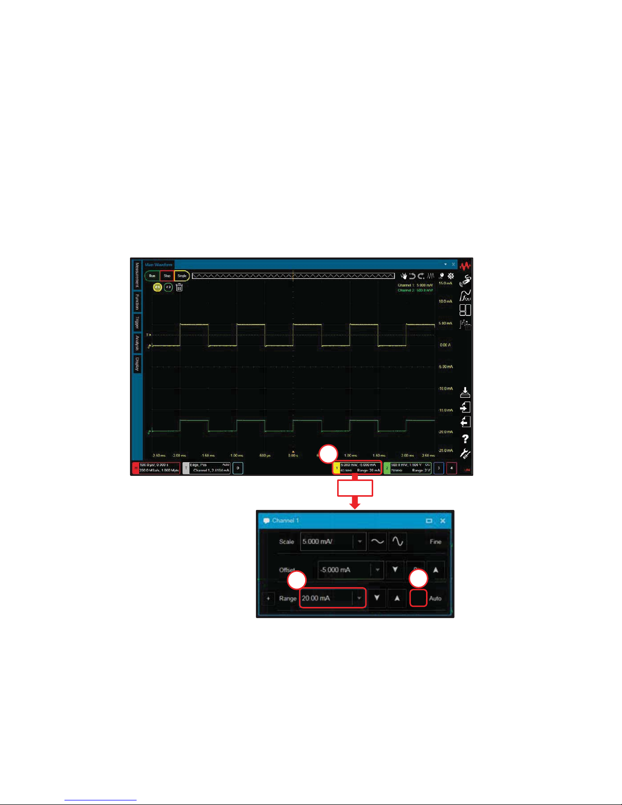
How to change the current range
1. Click on the Channel summary to open the Channel mini dialog box.
2. Un-check “Auto”.
3. Select the “Range”.
Note:
- If “Auto” is enabled, a suitable range is selected automatically by the vertical
scale setting controlled by the Vertical scale control knob.
- The measurement bandwidth and the input resistor are automatically
changed by changing the range.
1
3
2
Click
16
Page 17

Keysight Technologies
CX3300 Current Waveform Analyzer
Quick Operation Guide
How to set the bandwidth limit
1. Click on the Channel summary to open the Channel mini dialog box.
2. Click on the “ ” at the upper right of the window to open the Setting dialog
box.
3. Select “ON”.
4. Set the bandwidth limit.
1
4
3
Setting
> Channels
> Channel X
2
17
Page 18
Keysight Technologies
CX3300 Current Waveform Analyzer
Quick Operation Guide
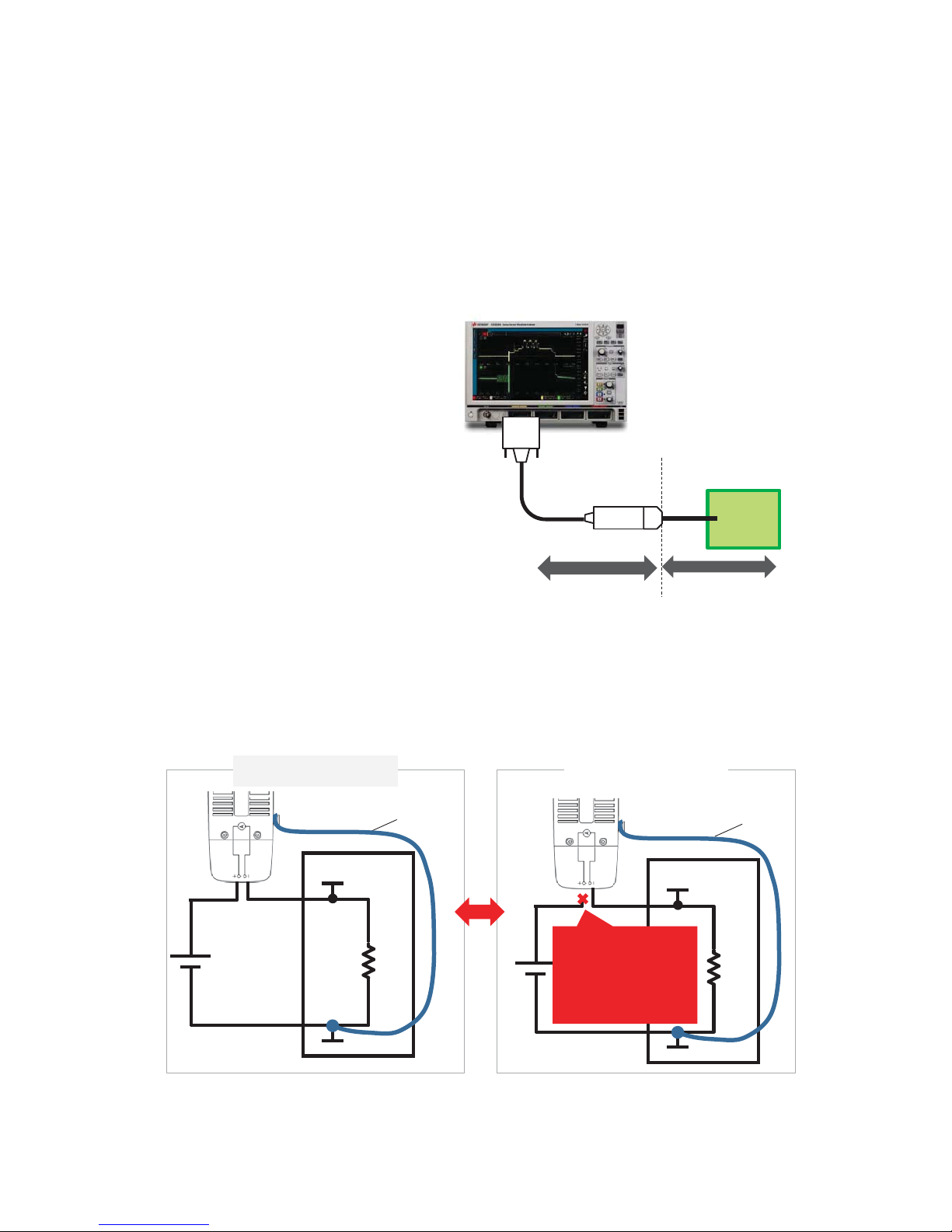
How to minimize the offset current
1. Perform “User Calibration”. The
offset current of the current
sensor will be minimized.
2. Perform a actual measurement
and fix the connection and the
CX3300 settings such as the
current range.
3. Perform a “Null” measurement.
DUT
Mainframe
+ Current Sensor
User Calibration Null
DUT
VIN
GND
Ground lead
Connection Example
DUT
VIN
GND
Ground lead
Actual measurement
Null measurement
3-1. Make a connection to prevent the current flow into the current sensor.
Note for connection:
- Connect either the (+) or (-) terminal of the current sensor to the stable voltage
on the DUT.
- Connect the ground lead to the circuit common of the DUT.
Remove the test lead
of the (+) terminal to
prevent the current
flow into the current
sensor
18
Page 19
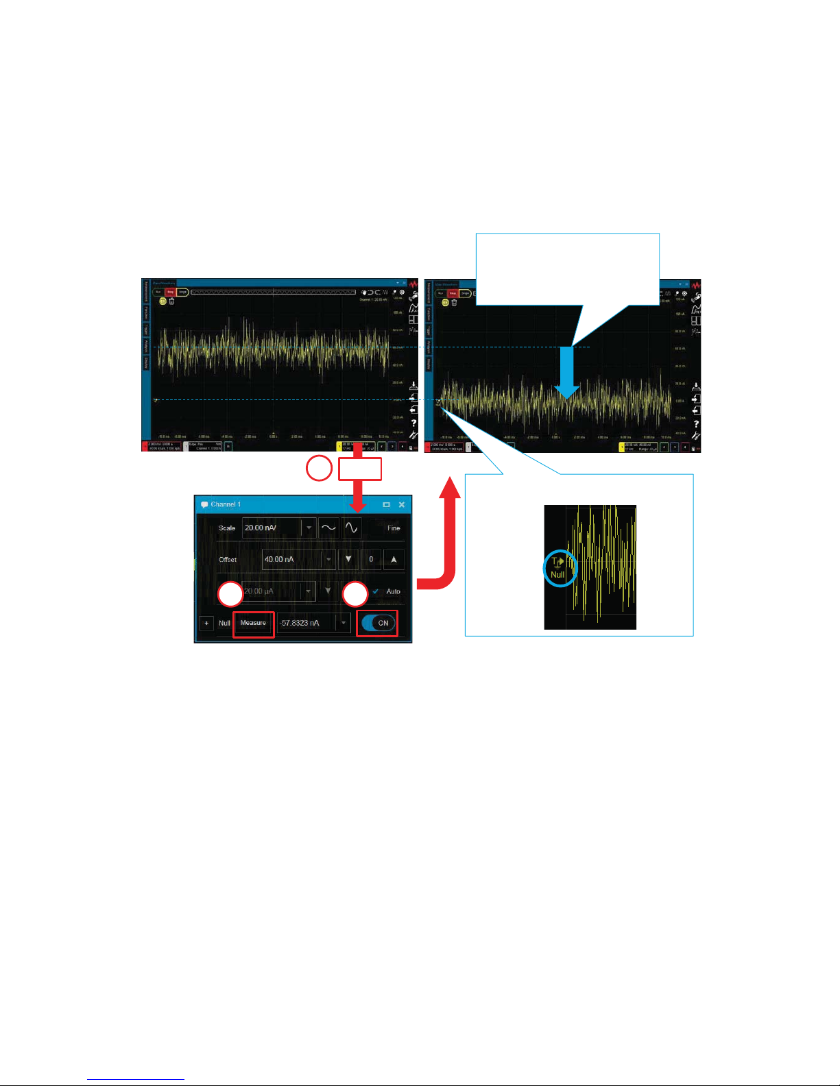
3-2. Null measurement
1. Click on the Channel summary to open the Channel mini dialog
box.
2. Turn “ON” the Null measurement.
3. Press “Measure”.
Click
1
3 2
The Null offset is
automatically subtracted
from the waveform
The Null indicator turned on.
4. Restore the connection then make an actual measurement again.
Note:
The Null offset is set to zero when:
- The current sensor is disconnected
- The User Calibration is performed
- The CX3300 is closed or turned off.
19
Page 20
Keysight Technologies
CX3300 Current Waveform Analyzer
Quick Operation Guide
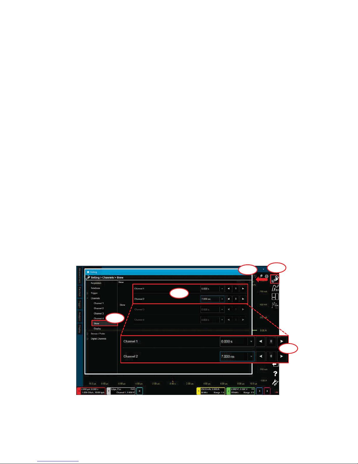
How to perform a Skew adjustment
The skew between the channels on the measurement device can be adjusted.
1. Preparation
1-1. Connect the Current Sensor (CX1101A/CX1102A/CX1103A) or the
Passive Probe Interface Adapter (CX1151A) to the device.
1-2. Execute the measurement.
2. Settings
2-1. Click on the “Setting” icon.
2-2. The “Setting” dialog box opens.
2-3. Click on “Setting>Channels>Skew".
2-4. The Skew setup panel opens and the waveforms for the effective
channels are shown behind the “Setting” dialog box.
2-5. Adjust the skew of the other channels to the triggered channel
while observing the waveforms behind the “Setting” dialog box.
Setting
Skew setup panel
2-1
2-2
2-3
2-5
2-4
20
Page 21

Keysight Technologies
CX3300 Current Waveform Analyzer
Quick Operation Guide
What determines the effective bandwidth of the instrument?
The effective bandwidth of the instrument is determined by the following settings
and displayed in each “Channel summary” on the front panel.
Summary bar
Channel summary
- Bandwidth options of the mainframe
- ADC (14-bit: High speed mode or 16-bit: High resolution mode)
For details of settings, please refer to “How to change the 14-bit or 16-bit
resolution?”.
- Measurement range
For details of settings, please refer to “How to change the current range?”.
-Sampling rate
For details of settings, please refer to “How to change the sampling rate?”.
- Bandwidth Limit
For details of settings, please refer to “How to set the bandwidth limit?”.
Tips: In addition, the connection type and the DUT can limit the actual
measurement bandwidth at DUT. Please refer to the application note, “7 Hints for
Precise Current Measurements with the CX3300 Series Device Current Waveform
Analyzer” (Literature number: 5992-2118) for more information.
21
Page 22

Keysight Technologies
CX3300 Current Waveform Analyzer
Quick Operation Guide
How to zoom in on the waveform
The CX3300 has two kinds of zoom in functions:
a. Zoom at single display
b. “Anywhere” Zoom.
a. Zoom at single display
a-1. Click on the “Move” icon to change the ‘Zoom” icon.
a-2. Drag the cursor until the displayed box covers the area of interest.
Move icon
Undo
Zoom icon
Redo
a
a-1
a-2
Drag
Tips: If you want to cancel the zoom, click the Undo icon.
22
Page 23

Tips: By using the Scale Reference function, you can change the base point of the Zoom.
- Utilities > Configuration > User Preference > Scale Reference
Utilities
1
2
3
4
[ Scale Reference > Horizontal Sample
]
0 s 4 ms
[ “Timebase” selected ]
4 ms
[ “0 s” selected ]
0. s
Stretch around 0 s
Stretch around the timebase center
Note:
- The setting is also retained in CX3300
power cycle and [Default Setup].
- It returns to the factory condition with
[Factory Default]
1
.
1. [Factory Default] can be selected on the “Utilities >
Configuration > Setups” window.
23
Page 24

b. “Anywhere” Zoom
b-1. Click on the “Waveforms” icon.
b-2. Click on the "1 & zoom" icon.
b-3. Drag the boundary line of the area.
Tips: You can also specify the scale and position on the Axis dialog.
Double-Click
Double-Click
2
Drag
Move
b-1
b-2
b-3
b
24
Page 25

Keysight Technologies
CX3300 Current Waveform Analyzer
Quick Operation Guide
How to use the waveform memory
1. Click on the “Analysis” icon to open the “Analysis” dialog box.
2. Select “Waveform Memories”.
3. Select “ON”.
4. Select “Memory X” ( X is a number. X=1 in this case. )
5. Press [Load]. The waveform is loaded from Memory X.
6. Change the color, if necessary.
1
2
3
4
5
6
Analysis
Memory 1
Channel1
Icon for Memory 1 is shown.
25
Page 26

Keysight Technologies
CX3300 Current Waveform Analyzer
Quick Operation Guide
How to overlay multiple acquisitions
1. ON : Display > Persistence > Infinity
1-1. Click the “Display” icon on the Tool Palette.
1-2. Select “Persistence” on the Display tool palette.
1-3. Drag and drop the “Infinity” icon on the Display tool palette onto the
area of interest on the waveform.
1-1
1-2
Normal
1-3
Infinity
26
Page 27

2. OFF : Display > Persistence > Normal
2-1. Click the “Display” icon on the Tool Palette.
2-2. Select “Persistence” on the Display tool palette.
2-3. Drag and drop the “Normal” icon on the Display tool palette onto the
area of interest on the waveform.
2-1
2-2
Infinity
2-3
Normal
27
Page 28

Keysight Technologies
CX3300 Current Waveform Analyzer
Quick Operation Guide
How to display the secondary Y axis
1. Select “Axis” in the Display Tool Pallet. Then, drag and drop the “X1, Y1 and
Y2” icon on the waveform.
1
2
3
Y2
axis
Y1
axis
28
Page 29

2. How to delete the secondary Y Axis.
There are 2 ways to delete the secondary Y Axis.
2-1. Drag and drop the “Display > Axis > X1 and Y 1” icon.
2-2. Double-click somewhere on the screen and switch OFF the
“Secondary Y Axis” on the “Plot Properties” window.
OFF ĴON
29
Page 30

Keysight Technologies
CX3300 Current Waveform Analyzer
Quick Operation Guide
How to set the Trigger
1. Press [Sweep] to set the Trigger to ON.
2. Select the Trigger Type. ( Default: “Edge” )
2-1. Select “Trigger” on the Tool Palette
2-2. Select the Trigger Type ( “Edge” in this case ) from the Trigger Tool
Palette
2-3. Drag-and-drop the icon onto the target waveform. The color of the icon
shows the target waveform.
Trigger Controls
3
The color of the icon shows
the target waveform
1
Trigger summary
2-1
2-3
Drag & drop
2-2
30
Page 31

3
3. Change the trigger source, slope and level using either:
a) The Trigger Controls
OR
b) The Trigger Mini dialog box.
4. For more detailed conditions, open the “Setting > Trigger dialog box” by either:
a) Pressing the [Menu] button
OR
b) Clicking the “ ” at the upper right of the Trigger mini dialog
box.
Trigger Controls
Trigger Summary
3-a
3-b
4-b
4-a
31
Page 32

1. Apply a Measurement Function (“+width” in this case)
1-1. Click the “Measurement” icon on the Tool Palette.
1-2. Drag and drop the “+width” icon onto the target. The color of the
icon shows the target waveform.
Keysight Technologies
CX3300 Current Waveform Analyzer
Quick Operation Guide
How to apply a Measurement Function
1-1
Measurement Stats window
Tool Palette
1-2
32
Page 33

2. For more detailed conditions, open the Measurements pane by clicking the
Setting icon on the Measurement Stats window and change the settings.
2-1
Click
Click the Measurement 1 menu
2-3
Double-click the Measurements menu
2-2
You can also access the Measurement pane via Side Bar > Analysis >
Measurement.
3. Turn the measurement function off.
3-2
3-1
Select the line
Turn off all functions
Click Delete
You can switch the measurement function ON and OFF on the
Measurement pane as described in procedure 2.
33
Page 34

Keysight Technologies
CX3300 Current Waveform Analyzer
Quick Operation Guide
How to apply the A-B marker
1. Turn the Marker ON.
1-1. Click “Display” on the Tool Palette.
1-2. Click “Markers”.
1-3. Drag and drop the A-B marker icon onto the target. The color of the
icon shows the target waveform.
1-4. Move X1 and X2 to the target point.
Marker Results window
1-1
Tool Palette
1-3
1-2
1-4
Tips: You can switch the Marker Results window
ON and OFF via Side Bar > Layout > Marker
Results.
Side Bar
34
Page 35

3-1
Tool Palette
3-3
3. Turn the Marker OFF.
3-1. Click “Display” on the Tool Palette.
3-2. Click “Markers”.
3-3. Drag and drop the OFF icon onto the target.
2. For more detailed conditions, open the Markers dialog box by clicking the
Setting icon on the Marker Results window and change the settings.
2-1
2-2
Click
3-2
35
Page 36

Keysight Technologies
CX3300 Current Waveform Analyzer
Quick Operation Guide
How to place pointers on waveforms
1. Select “Markers” in the Display Tool Pallet. Then, drag and drop the “Cross”
icon on the point that you want to monitor.
1
2
3
You can monitor multiple points
by repeating drag and drop.
36
Page 37

2. How to delete the Cross Hair Marker.
There are 3 ways to delete the cross hair marker.
2-1. Right-click the mouse on the cross hair marker and choose “Delete”.
2-2. Click the gear icon on the upper right corner of the main screen.
Choose “Delete”.
Display options ( ON / OFF )
Delete the marker by “x” click
37
Page 38

2-3. Click the gear icon on the upper right corner of the “Marker” screen.
Delete the marker by “x” click
Display options ( ON / OFF )
Delete all markers by “x” or “Delete All” button.
1
2
38
Page 39

Tips :
- You can select whether or not the cross hair marker is tracked as follows:
Right-click the mouse on the cross hair marker.
Choose “Track”.
This cross hair marker can
be tracked on the
waveform in this mode.
This cross hair marker can
NOT be tracked on the
waveform in this mode.
39
Page 40

Keysight Technologies
CX3300 Current Waveform Analyzer
Quick Operation Guide
How to add an Annotation
1. Drag and drop the Display icon onto the target waveform.
1-1. Click the “Display” icon on the Tool Palette.
1-2. Click the “Annotations” tab.
1-3. Drag and drop the “Display” icon on the Display tool palette onto the
target waveform.
Tool Palette
1-1
1-2
Annotations
1-3
Drag & drop
No text
40
Page 41

3. How to delete the Annotation
You can delete the Annotation by right clicking on it, as shown with “Ch1”
in the example below, and selecting Delete.
2. How to edit the Annotation
2-1. Select Edit by right clicking on “No text”.
2-2. You can edit the Annotation.
2-1
2-2
Edit
Delete
41
Page 42

Keysight Technologies
CX3300 Current Waveform Analyzer
Quick Operation Guide
How to apply the post-filter
1. How to apply the post-filter
1-1. Click the “Function” icon on the Tool Palette.
1-2. Select “Filter” on the Function tool palette.
1-3. Drag and drop the “Smooth 100pts” icon on the Function tool palette
onto the area of interest on the waveform.
1-1
1-2
Icon for Function 1 is shown.
Smoothing Waveform
Original Waveform
1-3
42
Page 43

2. How to change the settings
2-1. Click on the “Analysis” icon to open the Analysis dialog box.
2-2. Select “Function 1”.
2-3. You can change the Smoothing Points.
Analysis
2-1
2-2
2-3
43
Page 44

Keysight Technologies
CX3300 Current Waveform Analyzer
Quick Operation Guide
How to perform the FFT ( Fast Fourier Transform )
1. How to apply the FFT
1-1. Click the “Analysis” icon on the Tool Palette.
1-2. Drag and drop the “Spectrum” icon on the Analysis tool palette onto
the chosen area of interest on the waveform.
Note:
- If the Zoom window is displayed in the lower half, the dragged icon is always
effective for the zoomed waveform.
1-1
1-2
Drag & drop
44
Page 45

2. How to change the FFT settings ?
2-1. Double-click anywhere on the horizontal axes in the Spectrum graph
view.
2-2. Un-check the “Auto” box.
2-3. Click this button until the Scale is 100.0KHz.
3. How to adjust the chosen area of interest on the waveform ?
The CX3300 has two ways in which to adjust the chosen area of interest.
a) Gating Function > FFT
b) Waveform Zoom > FFT
Refer to the next page for further details.
2-2
2-3
2-1
Spectrum graph
45
Page 46

a) Gating Function > FFT
b) Waveform Zoom > FFT
Adjust this area.
Gating
Horizontal Move
Note:
- The result of the FFT is changed in real time by adjusting the chosen area of
interest on the waveform.
46
Page 47

Keysight Technologies
CX3300 Current Waveform Analyzer
Quick Operation Guide
How to analyze the waveform in the specified area with an Area marker
1. Turn the Marker ON.
1-1. Click the “Display” icon on the Tool Palette.
1-2. Select “Markers”.
1-3. Drag and drop the “Area” icon on the Display tool palette onto the
specified area on the waveform.
1-1
1-2
1-3
There are four types of Area markers as follows; Area, Area (+width), Area (-width)
and Area (period).
Using the mouse drag and drop option, the Area marker allows you to freely
change the area range.
Using Area, Area (+width), Area (-width) and Area (period) marker, the area is
automatically determined according to where you drag and drop the marker.
[ Apply the “Area” marker ]
47
Page 48

2. Click and hold the mouse button, and horizontally drag the Start or Stop line
over the specified area of interest.
Infinity
Start
Stop
Baseline
Mean : The average current
from Start to Stop
Area
Horizontal Drag
[ Apply the “Area (+width), Area (-width), Area (period) marker” ]
1. Apply the “Area (+width) marker
For example, as with the Area marker, drag and drop the “Area (+width)”
icon on the Display tool palette onto the area of interest.
48
Page 49

2. The result of applying the "Area (+ width), Area (-width), Area (period) marker"
Area (+width)
Area (-width)
Area (period)
The area is automatically determined according to where you drop the
marker.
49
Page 50

Keysight Technologies
CX3300 Current Waveform Analyzer
Quick Operation Guide
How to apply the Power and Current Profiler
1. Drag and drop the Display icon onto the target waveform.
1-1. Click the “Analysis” icon on the Tool Palette.
1-2. Drag and drop the “Profiler” icon on the Analysis tool palette onto the
chosen area on the waveform.
Tool Palette
1-1
1-2
Drag & drop
50
Page 51

2-1
2-2
2. Perform the Auto Profile (Optional)
- The Auto Profile function can be used to help divide the segments
into levels to view the vertical level difference. You can also manually
adjust the levels of the segments.
2-1. Click the “Auto Profile” button to open the Auto Profile window.
2-2. Check the Condition
- Set the number of levels that you want to divide the segments
into for the Number of Y Levels.
- Set a resolution that is lower than the minimum resolution that
you want to divide into levels for the Y Step Resolution.
- Set the time which you want not to divide the different
segments for X Step Resolution.
To divide 7 levels
Ignore <40 s Do not ignore >140 s
Example
Min. ~200 $
of peak-to-peak of
the waveform
51
Page 52

2. Perform Auto Profile (Continued)
2-3. Click the “Perform” button.
2-3
52
Page 53

3. Adjust the position of the line of the segments manually.
3-1
3-2
3-3
3-4
Drag and drop
3-5
Reset zoom
Select “Zoom”.
2. Select the area to
zoom using the mouse.
Select “Profile”.
Drag New
53
Page 54

Keysight Technologies
CX3300 Current Waveform Analyzer
Quick Operation Guide
How to apply the XY analysis
1. How to apply the XY analysis
1-1. Click the “Analysis” icon on the Tool Palette.
1-2. Drag and drop the “XY” icon on the Analysis tool palette on the
channel set as Source1.
1-1
1-2
Drag and drop on the channel set as Source1.
Source1
Source2
54
Page 55

2. How to change the target channels
2-1. Double-click “X1” icon in the XY graph view.
2-2. Set the target channel as Source1 and Source2 on the XY1 window.
3. How to adjust the scale of the graph
3-1. Double-click anywhere on the horizontal or vertical axes in the XY
graph view.
3-2. Un-check the “Auto” box.
3-3. Adjust the scale on this area.
3-2
3-1
XY graph
3-3
XY graph
2-1
2-2
55
Page 56

4. How to adjust a specific area on the waveform.
4-1. Select “Gating” from “All/View/Gating” at the top left on the XY graph.
4-2. The result of the XY graph is changed in real time by adjusting the
specified area on the waveform.
Adjust this area.
4-1
4-2
56
Page 57

Keysight Technologies
CX3300 Current Waveform Analyzer
Quick Operation Guide
How to change the measurement units (Clone to Ampere Hour) in Area
analysis
1. Select “Markers” in the Display Tool Pallet, then drag and drop the “Area”
icon on the interest area on the waveform.
Changing from “C” to “Ah” is explained on the next page.
1
2
3
57
Page 58

Note:
- The setting is also retained in CX3300 power cycle and [Default Setup].
- It returns to the factory condition with [Factory Default]
1
.
1. [Factory Default] can be selected on the “Utilities > Configuration > Setups” window.
2. Select “Utilities > Configuration > User Preference” window.
Utilities
1
3
2
4
Change “C” to “Ah”.
The measurement unit is changed from “C” to “Ah”.
58
Page 59

Keysight Technologies
CX3300 Current Waveform Analyzer
Quick Operation Guide
How to perform User calibration
User calibration is effective for making more accurate measurements by allowing
you to perform error corrections of measurement data.
1. Before starting the user calibration, connect the CX1100 to the CX3300
analog input channel.
Note:
- If you connect the CX1101A/CX1102A, attach the CX1203A sensor head to it
DQGVHWWKH&;$VOLGHVZLWFKWRő
59
Page 60

2. How to perform User calibration ?
2-1. Click on the “Utilities” icon to open the Utilities menu.
2-2. Click “Configuration” to open the “Configuration” dialog box.
2-3. Click “User Calibration” to display the “Configuration>User Calibration”
screen.
2-4. Select the “Gain/Offset” or “Offset” radio button for the channel under
user calibration.
2-5. Click the “Execute” button of the channel.
2-6. The dialog box which asks you to connect the CX1100 input to the Aux
Out terminal is shown. If you are ready, click the “OK” button.
The user calibration will start.
After the user calibration finishes,
the ON/OFF switch will be available.
Note:
- The data is not cleared by turning the CX3300 off.
- Once you disconnect the CX1100 from the CX3300, the user calibration
data for this channel will be cleared.
Utilities
2-1
2-2
2-3
2-4
2-5
60
Page 61

Keysight Technologies
CX3300 Current Waveform Analyzer
Quick Operation Guide
How to check the firmware revisions
1. Click on the "About Device Current Waveform Analyzer" icon.
2. The “About CX3300 Device Current Waveform Analyzer” window will open.
3. The Firmware revisions are displayed.
About the Device Current Waveform Analyzer
1
2
3
61
Page 62

Keysight Technologies
CX3300 Current Waveform Analyzer
Quick Operation Guide
How to simulate the 50 MHz or 100 MHz bandwidth option
on the mainframe with the 200 MHz option.
The mainframe has three maximum bandwidth options, 50 MHz, 100 MHz and
200 MHz. In order to simulate the 50 MHz or 100 MHz option on the mainframe
with the 200 MHz option, follow the procedure below.
1. Click on the “Setting” icon.
2. The “Setting” dialog box opens.
3. Click on "Setting>Channels>Channel 1" to open the channel 1 setup panel.
4. Set the Bandwidth Limit setting to "ON".
5. Set the “Bandwidth Limit” to 50 MHz for checking the performance of the 50
MHz option and to 100 MHz for checking the performance of the 100 MHz
option.
Setting
1
2
3
4
5
62
Page 63

Keysight Technologies
CX3300 Current Waveform Analyzer
Quick Operation Guide
Where to find the Online help
1. Click the “Help” icon on the Side Bar.
2. Click the “On-line Help (.chm)” button to open the online help.
Help
Side Bar
1
2
63
Page 64

Keysight Technologies
CX3300 Current Waveform Analyzer
Quick Operation Guide
How to display the menu bar
There are two ways to display the menu bar.
1. Hover the mouse arrow over the upper edge of the monitor.
2. Click the blue bar at the top of the monitor, or click any other area.
Menu Bar
Note:
- By selecting “Utilities> Menu Bar” from the Menu Bar, it is displayed at all
times. By doing the same operation again, you can hide the Menu Bar.
- The setting is also retained in CX3300 power cycle and [Default Setup].
- It returns to the factory condition with [Factory Default]
1
.
1. [Factory Default] can be selected on the “Utilities > Configuration > Setups” window.
64
Page 65

Page 66

This information is subject to change without notice.
© Keysight Technologies 2018
Edition 1, June 2018
*CX3300-90300*
CX3300-90300
www.keysight.com
 Loading...