

Page 1
Keysight Technologies B1505A
Power Device Analyzer/Curve Tracer
Configuration and
Connection Guide
Page 2

Notices
© Keysight Technologies 2009-2020
No part of this manual may be reproduced in
any form or by any means (including electronic storage and retrieval or translation into
a foreign language) without prior agreement
and written consent from Keysight Technologies as governed by United States and international copyright laws.
Manual Part Number
B1505-90090
Edition
Edition 1, June 2009
Edition 2, November 2009
Edition 3, May 2010
Edition 4, August 2010
Edition 5, February 2011
Edition 6, September 2012
Edition 7, April 2013
Edition 8, September 2015
Edition 9, November 2015
Edition 10, December 2015
Edition 11, July 2019
Edition 12, November 2020
Published by:
Keysight Technologies Japan K.K.
9-1, Takakura-cho, Hachioji-shi, Tokyo
192-8550 Japan
Warranty
Restricted Rights Legend
If software is for use in the performance of a
U.S. Government prime contract or subcontract, Software is delivered and licensed as
“Commercial computer software” as defined
in DFAR 252.227-7014 (June 1995), or as a
“commercial item” as defined in FAR 2.101(a)
or as “Restricted computer software” as
defined in FAR 52.227-19 (June 1987) or any
equivalent agency regulation or contract
clause. Use, duplication or disclosure of Software is subject to Keysight Technologies’
standard commercial license terms, and nonDOD Departments and Agencies of the U.S.
Government will receive no greater than
Restricted Rights as defined in FAR 52.22719(c)(1-2) (June 1987). U.S. Government
users will receive no greater than Limited
Rights as defined in FAR 52.227-14 (June
1987) or DFAR 252.227-7015 (b)(2) (November 1995), as applicable in any technical
data.
The material contained in this document
is provided “as is,” and is subject to
being changed, without notice, in future
editions. Further, to the maximum extent
permitted by applicable law, Keysight
disclaims all warranties, either express
or implied, with regard to this manual
and any information contained herein,
including but not limited to the implied
warranties of merchantability and fitness
for a particular purpose. Keysight shall
not be liable for errors or for incidental
or consequential damages in connection
with the furnishing, use, or performance
of this document or of any information
contained herein. Should Keysight and
the user have a separate written agreement with warranty terms covering the
material in this document that conflict
with these terms, the warranty terms in
the separate agreement shall control.
Technology Licenses
The hardware and/or software described in
this document are furnished under a license
and may be used or copied only in accordance with the terms of such license.
Page 3

Page 4

In This Document
This document provides the following information about Keysight B1505A Power Device
Analyzer/Curve Tracer.
1. Configuration Guide
Describes how to configure the B1505A.
2. N1259A Connection Guide
Describes how to connect the B1505A, the N1259A Test Fixture, and a device und
).
(DUT
3. N1265A Connection Guide
Describes how to connect the B1505A, the N1265A Test Fixture, and a device und
).
(DUT
4. N1272A and N1273A Connection Guide
Describes how to connect the B1505A, the N1273A Capacitance Test Fixture, and a device
under test (DUT).
5. Connection Guide for Wafer Prober and Your Own Test Fixture
Describes how to connect the B1505A, accessories, and a DUT interface such as wafer prober
and your own test fixture.
6. Accessory Dimensions
Describes dimensions and weight of accessories.
7. Connection and Ordering Examples
Describes prober connection and ordering examples.
er test
er test
Page 5

Contents
1. Configuration Guide
Measurement Resources . . . . . . . . . . . . . . . . . . . . . . . . . . . . . . . . . . . . . . . . . . . . . . . . . . . .1-3
B1505A Mainframe Furnished Accessories. . . . . . . . . . . . . . . . . . . . . . . . . . . . . . . . . . . . . .1-5
B1505A Modules and Mainframe Options. . . . . . . . . . . . . . . . . . . . . . . . . . . . . . . . . . . . . . .1-7
Module type and locations . . . . . . . . . . . . . . . . . . . . . . . . . . . . . . . . . . . . . . . . . . . . . . . . .1-9
N1259A Test Fixture for Power Device . . . . . . . . . . . . . . . . . . . . . . . . . . . . . . . . . . . . . . . .1-11
N1265A Ultra High Current Expander/Fixture . . . . . . . . . . . . . . . . . . . . . . . . . . . . . . . . . .1-17
N1266A High Voltage Source Monitor Unit Current Expander . . . . . . . . . . . . . . . . . . . . .1-25
N1266A Compatibility with Fixture and Module Selector . . . . . . . . . . . . . . . . . . . . . . .1-27
N1267A High Voltage Source Monitor Unit / High Current Source Monitor Unit
Fast Switch. . . . . . . . . . . . . . . . . . . . . . . . . . . . . . . . . . . . . . . . . . . . . . . . . . . . . . . . . . . . . . .1-29
N1268A Ultra High Voltage Expander . . . . . . . . . . . . . . . . . . . . . . . . . . . . . . . . . . . . . . . . .1-31
N1271A Thermal Test Enclosure and Related Accessories . . . . . . . . . . . . . . . . . . . . . . . .1-35
Measurement Capability on Thermal Test . . . . . . . . . . . . . . . . . . . . . . . . . . . . . . . . . . . .1-39
Information of inTEST Thermal Plate and Thermostream. . . . . . . . . . . . . . . . . . . . . . . .1-39
Pre-configured Power Device Analyzer/Curve Tracer (B1505A with
Modules/Fixture) . . . . . . . . . . . . . . . . . . . . . . . . . . . . . . . . . . . . . . . . . . . . . . . . . . . . . . . . . .1-40
Accessories for Wafer Prober and Your Own Test Fixture . . . . . . . . . . . . . . . . . . . . . . . . .1-48
Other Accessories . . . . . . . . . . . . . . . . . . . . . . . . . . . . . . . . . . . . . . . . . . . . . . . . . . . . . . . . .1-57
Retrofit Products for B1505A . . . . . . . . . . . . . . . . . . . . . . . . . . . . . . . . . . . . . . . . . . . . . . . .1-61
Conversion Kit from B1500A to B1505A . . . . . . . . . . . . . . . . . . . . . . . . . . . . . . . . . . . . . . .1-64
Upgrade Kit for N1259AU Test Fixture . . . . . . . . . . . . . . . . . . . . . . . . . . . . . . . . . . . . . . . .1-65
Upgrade Kit for N1265AU Test Fixture . . . . . . . . . . . . . . . . . . . . . . . . . . . . . . . . . . . . . . . .1-69
Note for 4142B Users . . . . . . . . . . . . . . . . . . . . . . . . . . . . . . . . . . . . . . . . . . . . . . . . . . . . . .1-74
2. N1259A Connection Guide
Input Connection. . . . . . . . . . . . . . . . . . . . . . . . . . . . . . . . . . . . . . . . . . . . . . . . . . . . . . . . . . .2-3
To Connect Interlock Circuit. . . . . . . . . . . . . . . . . . . . . . . . . . . . . . . . . . . . . . . . . . . . . . . .2-4
Output Connection . . . . . . . . . . . . . . . . . . . . . . . . . . . . . . . . . . . . . . . . . . . . . . . . . . . . . . . . .2-8
To Connect DUT . . . . . . . . . . . . . . . . . . . . . . . . . . . . . . . . . . . . . . . . . . . . . . . . . . . . . . . . .2-9
To Use Options . . . . . . . . . . . . . . . . . . . . . . . . . . . . . . . . . . . . . . . . . . . . . . . . . . . . . . . . .2-12
N1259A-010 Inline Package Socket module . . . . . . . . . . . . . . . . . . . . . . . . . . . . . . . . .2-19
N1259A-011 Universal Socket Module. . . . . . . . . . . . . . . . . . . . . . . . . . . . . . . . . . . . . .2-20
N1259A-012 Blank PTFE Board. . . . . . . . . . . . . . . . . . . . . . . . . . . . . . . . . . . . . . . . . . . .2-21
N1259A-013 Curve Tracer Test Adapter Socket Module . . . . . . . . . . . . . . . . . . . . . . .2-22
Keysight B1505A Configuration and Connection Guide
Page 6

Contents
N1259A-014 Gate Charge Socket Module . . . . . . . . . . . . . . . . . . . . . . . . . . . . . . . . . . 2-23
3. N1265A Connection Guide
Input Connection . . . . . . . . . . . . . . . . . . . . . . . . . . . . . . . . . . . . . . . . . . . . . . . . . . . . . . . . . . .3-4
To Connect Interlock Circuit. . . . . . . . . . . . . . . . . . . . . . . . . . . . . . . . . . . . . . . . . . . . . . . .3-5
Output Connection . . . . . . . . . . . . . . . . . . . . . . . . . . . . . . . . . . . . . . . . . . . . . . . . . . . . . . . . .3-9
To Connect DUT . . . . . . . . . . . . . . . . . . . . . . . . . . . . . . . . . . . . . . . . . . . . . . . . . . . . . . . 3-10
Inline Package Socket module (N1265A-010) . . . . . . . . . . . . . . . . . . . . . . . . . . . . . . . 3-17
Universal Socket Module (N1265A-011) . . . . . . . . . . . . . . . . . . . . . . . . . . . . . . . . . . . 3-18
Curve Tracer Test Adapter Socket Module (N1265A-013) . . . . . . . . . . . . . . . . . . . . . 3-19
Gate Charge Socket Module (N1265A-014) . . . . . . . . . . . . . . . . . . . . . . . . . . . . . . . . . 3-20
Blank Silicon Plate (N1265A-002) . . . . . . . . . . . . . . . . . . . . . . . . . . . . . . . . . . . . . . . . . 3-22
Universal R-Box (N1265A-035) . . . . . . . . . . . . . . . . . . . . . . . . . . . . . . . . . . . . . . . . . . . 3-23
Protection Adapter (N1265A-040). . . . . . . . . . . . . . . . . . . . . . . . . . . . . . . . . . . . . . . . . 3-25
Container (N1265A-045) . . . . . . . . . . . . . . . . . . . . . . . . . . . . . . . . . . . . . . . . . . . . . . . . 3-25
Prober System Cable (N1254A-524) . . . . . . . . . . . . . . . . . . . . . . . . . . . . . . . . . . . . . . . 3-25
4. N1272A and N1273A Connection Guide
Input Connection . . . . . . . . . . . . . . . . . . . . . . . . . . . . . . . . . . . . . . . . . . . . . . . . . . . . . . . . . . .4-3
To Connect Interlock Circuit. . . . . . . . . . . . . . . . . . . . . . . . . . . . . . . . . . . . . . . . . . . . . . . .4-3
N1272A Device Capacitance Selector . . . . . . . . . . . . . . . . . . . . . . . . . . . . . . . . . . . . . . . .4-3
Output Connection . . . . . . . . . . . . . . . . . . . . . . . . . . . . . . . . . . . . . . . . . . . . . . . . . . . . . . . . .4-8
To Connect DUT . . . . . . . . . . . . . . . . . . . . . . . . . . . . . . . . . . . . . . . . . . . . . . . . . . . . . . . . .4-8
3-pin Inline Package Socket Module. . . . . . . . . . . . . . . . . . . . . . . . . . . . . . . . . . . . . . . . .4-9
N1273A-011 Universal Socket Module. . . . . . . . . . . . . . . . . . . . . . . . . . . . . . . . . . . . . 4-11
N1273A-013 Curve Tracer Test Adapter Socket Module . . . . . . . . . . . . . . . . . . . . . . 4-14
Accessories for Connecting a DUT. . . . . . . . . . . . . . . . . . . . . . . . . . . . . . . . . . . . . . . . . 4-15
5. Connection Guide for Wafer Prober and Your Own Test Fixture
Connection Overview . . . . . . . . . . . . . . . . . . . . . . . . . . . . . . . . . . . . . . . . . . . . . . . . . . . . . . .5-4
To Connect High Voltage R-Box . . . . . . . . . . . . . . . . . . . . . . . . . . . . . . . . . . . . . . . . . . . . 5-14
To Use Universal R-Box . . . . . . . . . . . . . . . . . . . . . . . . . . . . . . . . . . . . . . . . . . . . . . . . . 5-15
To Connect HCSMU Adapter . . . . . . . . . . . . . . . . . . . . . . . . . . . . . . . . . . . . . . . . . . . . . . . 5-17
To Connect Dual HCSMU Adapter . . . . . . . . . . . . . . . . . . . . . . . . . . . . . . . . . . . . . . . . . . . 5-20
To Connect 16493S-020 . . . . . . . . . . . . . . . . . . . . . . . . . . . . . . . . . . . . . . . . . . . . . . . . 5-20
To Connect 16493S-021 . . . . . . . . . . . . . . . . . . . . . . . . . . . . . . . . . . . . . . . . . . . . . . . . 5-22
To Connect Protection Adapter . . . . . . . . . . . . . . . . . . . . . . . . . . . . . . . . . . . . . . . . . . . . . 5-23
To Connect High Voltage Bias Tee. . . . . . . . . . . . . . . . . . . . . . . . . . . . . . . . . . . . . . . . . . . 5-25
Keysight B1505A Configuration and Connection Guide
Page 7

Contents
To Connect Module Selector . . . . . . . . . . . . . . . . . . . . . . . . . . . . . . . . . . . . . . . . . . . . . . . .5-27
To Connect HVSMU/HCSMU Fast Switch. . . . . . . . . . . . . . . . . . . . . . . . . . . . . . . . . . . . . .5-32
To Connect HVSMU Current Expander . . . . . . . . . . . . . . . . . . . . . . . . . . . . . . . . . . . . . . . .5-34
To Connect Ultra High Current Expander . . . . . . . . . . . . . . . . . . . . . . . . . . . . . . . . . . . . . .5-36
Connecting System Cable to N1265A . . . . . . . . . . . . . . . . . . . . . . . . . . . . . . . . . . . . . . .5-37
To Connect Ultra High Voltage Expander . . . . . . . . . . . . . . . . . . . . . . . . . . . . . . . . . . . . . .5-38
To Connect Device Capacitance Selector . . . . . . . . . . . . . . . . . . . . . . . . . . . . . . . . . . . . . .5-40
To Connect Gate Charge Adapter . . . . . . . . . . . . . . . . . . . . . . . . . . . . . . . . . . . . . . . . . . . .5-43
To Connect N1274A . . . . . . . . . . . . . . . . . . . . . . . . . . . . . . . . . . . . . . . . . . . . . . . . . . . . .5-44
To Connect N1275A . . . . . . . . . . . . . . . . . . . . . . . . . . . . . . . . . . . . . . . . . . . . . . . . . . . . .5-45
To Install an Interlock Circuit . . . . . . . . . . . . . . . . . . . . . . . . . . . . . . . . . . . . . . . . . . . . . . . .5-47
Procedure . . . . . . . . . . . . . . . . . . . . . . . . . . . . . . . . . . . . . . . . . . . . . . . . . . . . . . . . . . . . .5-48
To Connect Interlock Circuit. . . . . . . . . . . . . . . . . . . . . . . . . . . . . . . . . . . . . . . . . . . . . . .5-49
About Cable Connections . . . . . . . . . . . . . . . . . . . . . . . . . . . . . . . . . . . . . . . . . . . . . . . . . . .5-50
To Make Connection to Reduce Leakage Current . . . . . . . . . . . . . . . . . . . . . . . . . . . . .5-51
To Make Connection to Measure Low Resistance . . . . . . . . . . . . . . . . . . . . . . . . . . . . .5-52
To Connect UHVU/HVSMU/HVMCU Output . . . . . . . . . . . . . . . . . . . . . . . . . . . . . . . . .5-53
6. Accessory Dimensions
7. Connection and Ordering Examples
Package Device Measurement Configuration Examples . . . . . . . . . . . . . . . . . . . . . . . . . . .7-3
3kV, 20A Configuration (B1505AP-H20 equivalent). . . . . . . . . . . . . . . . . . . . . . . . . . . . .7-4
3kV, 20A with Capacitance Measurement Configuration (B1505AP-H21
equivalent) . . . . . . . . . . . . . . . . . . . . . . . . . . . . . . . . . . . . . . . . . . . . . . . . . . . . . . . . . . . . . .7-6
3 kV, 500 A or 1500 A Configuration (B1505AP-H50 or B1505AP-H70 equivalent). . .7-8
3 kV, 500 A or 1500 A with Capacitance Measurement Configuration
(B1505AP-H51 or B1505AP-H71 equivalent) . . . . . . . . . . . . . . . . . . . . . . . . . . . . . . . .7-10
10 kV, 500 A or 1500 A Configuration (B1505AP-U50 or B1505AP-U70
equivalent) . . . . . . . . . . . . . . . . . . . . . . . . . . . . . . . . . . . . . . . . . . . . . . . . . . . . . . . . . . . . .7-12
Add High Resolution Measurement (10 fA resolution with MPSMU or HPSMU)
Capability to 3 kV, 20 A Configuration. . . . . . . . . . . . . . . . . . . . . . . . . . . . . . . . . . . . . . .7-14
3 kV, 20A, High Voltage Medium Current Configuration . . . . . . . . . . . . . . . . . . . . . . . .7-16
3 kV, 40 A Configuration . . . . . . . . . . . . . . . . . . . . . . . . . . . . . . . . . . . . . . . . . . . . . . . . . .7-18
Add High Resolution Measurement Capability (10 fA resolution with MPSMU
or HPSMU) to 3 kV, 500A Configuration . . . . . . . . . . . . . . . . . . . . . . . . . . . . . . . . . . . . .7-21
10 kV, 500 A, High Voltage Medium Current Configuration . . . . . . . . . . . . . . . . . . . . .7-23
Configuration Examples for Lateral Device Measurement with Wafer Prober . . . . . . . . .7-25
3 kV, 20 A Measurement for On-Wafer Lateral Device. . . . . . . . . . . . . . . . . . . . . . . . . .7-26
Keysight B1505A Configuration and Connection Guide
Page 8

Contents
3 kV, 20 A, Capacitance Measurement for On-Wafer Lateral Device . . . . . . . . . . . . . 7-30
Add High Resolution Measurement (10 fA resolution with MPSMU or HPSMU)
Capability to 3 kV, 20 A, Capacitance Measurement for On-Wafer Lateral Device . . 7-33
3 kV, 40 A Measurement for On-Wafer Lateral Device. . . . . . . . . . . . . . . . . . . . . . . . . 7-35
3 kV, 500 A Measurement for On-Wafer Lateral Device. . . . . . . . . . . . . . . . . . . . . . . . 7-38
3 kV, 500 A, Capacitance Measurement for On-Wafer Lateral Device . . . . . . . . . . . . 7-40
3 kV, 500 A, High Voltage Medium Current Measurement for On-Wafer
Lateral Device . . . . . . . . . . . . . . . . . . . . . . . . . . . . . . . . . . . . . . . . . . . . . . . . . . . . . . . . . 7-42
10 kV, 500 A Measurement for On-Wafer Lateral Device. . . . . . . . . . . . . . . . . . . . . . . 7-44
Configuration Examples for Vertical Device Measurement with Wafer Prober. . . . . . . . 7-46
3 kV, 20 A Measurement for On-Wafer Vertical Device . . . . . . . . . . . . . . . . . . . . . . . . 7-47
3 kV, 20 A, Capacitance Measurement for On-Wafer Vertical Device. . . . . . . . . . . . . 7-51
Add High Resolution Measurement (10 fA resolution with MPSMU or HPSMU)
Capability to 3 kV, 20 A, Capacitance Measurement for On-Wafer Vertical Device. . 7-54
3 kV, 40 A Measurement for On-Wafer Vertical Device . . . . . . . . . . . . . . . . . . . . . . . . 7-56
3 kV, 500 A Measurement for On-Wafer Vertical Device . . . . . . . . . . . . . . . . . . . . . . . 7-59
3 kV, 500 A, Capacitance Measurement for On-Wafer Vertical Device. . . . . . . . . . . . 7-60
3 kV, 500 A, High Voltage Medium Current Measurement for On-Wafer
Vertical Device. . . . . . . . . . . . . . . . . . . . . . . . . . . . . . . . . . . . . . . . . . . . . . . . . . . . . . . . . 7-62
10 kV, 500 A Measurement for On-Wafer Vertical Device . . . . . . . . . . . . . . . . . . . . . . 7-64
GaN Current Collapse / Dynamic On-Resistance Measurement System
using the N1267A . . . . . . . . . . . . . . . . . . . . . . . . . . . . . . . . . . . . . . . . . . . . . . . . . . . . . . . . 7-66
Non-Kelvin Connection with the N1259A Test Fixture for Package Device . . . . . . . . 7-66
Kelvin Connection with the N1259A Test Fixture for Package Device . . . . . . . . . . . . 7-68
Non-Kelvin Connection with Prober for On-Wafer Lateral Device . . . . . . . . . . . . . . . 7-70
Kelvin Connection with Prober for On-Wafer Lateral Device . . . . . . . . . . . . . . . . . . . . 7-72
Upgrading from existing B1505A. . . . . . . . . . . . . . . . . . . . . . . . . . . . . . . . . . . . . . . . . . . . 7-74
Example of how to upgrade existing B1505A . . . . . . . . . . . . . . . . . . . . . . . . . . . . . . . . 7-76
Keysight B1505A Configuration and Connection Guide
Page 9

1 Configuration Guide
Page 10

Configuration Guide
Keysight B1505A Power Device Analyzer/Curve Tracer can meet the requirements of
modern power devices evaluations. You can configure a B1505A system from a wide
variety of measurement resources that best meets your needs today and also permits
expansion in future. Please specify the B1505A’s module configuration and accessories
you desire properly.
This chapter is a guide for configuring your B1505A system, and consists of the following
sections.
• "Measurement Resources"
• "B1505A Mainframe Furnished Accessories"
• "B1505A Modules and Mainframe Options"
• "N1259A Test Fixture for Power Device"
• "N1265A Ultra High Current Expander/Fixture"
• "N1266A High Voltage Source Monitor Unit Current Expander"
• "N1267A High Voltage Source Monitor Unit / High Current Source Monitor Unit Fast
Switch"
• "N1268A Ultra High Voltage Expander"
• "N1271A Thermal Test Enclosure and Related Accessories"
• "Pre-configured Power Device Analyzer/Curve Tracer (B1505A with
Modules/Fixture)"
• "Accessories for Wafer Prober and Your Own Test Fixture"
• "Other Accessories"
• "Retrofit Products for B1505A"
• "Conversion Kit from B1500A to B1505A"
• "Upgrade Kit for N1259AU Test Fixture"
• "Upgrade Kit for N1265AU Test Fixture"
• "Note for 4142B Users"
1-2 Keysight B1505A Configuration and Connection Guide
Page 11

Measurement Resources
Keysight B1505A can be equipped with the following measurement resources.
• “HPSMU - High Power SMU”
• “HCSMU - High Current SMU”
• “HVSMU - High Voltage SMU”
• “MPSMU - Medium Power SMU”
• “MCSMU - Medium Current SMU”
• “UHCU - Ultra High Current Unit”
• “HVMCU - High Voltage Medium Current Unit”
• “UHVU - Ultra High Voltage Unit”
• “MFCMU - Multi Frequency CMU”
Figure 1-1 B1505A Measurement Resources
Configuration Guide
Measurement Resources
Keysight B1505A Configuration and Connection Guide 1-3
Page 12
Configuration Guide
Measurement Resources
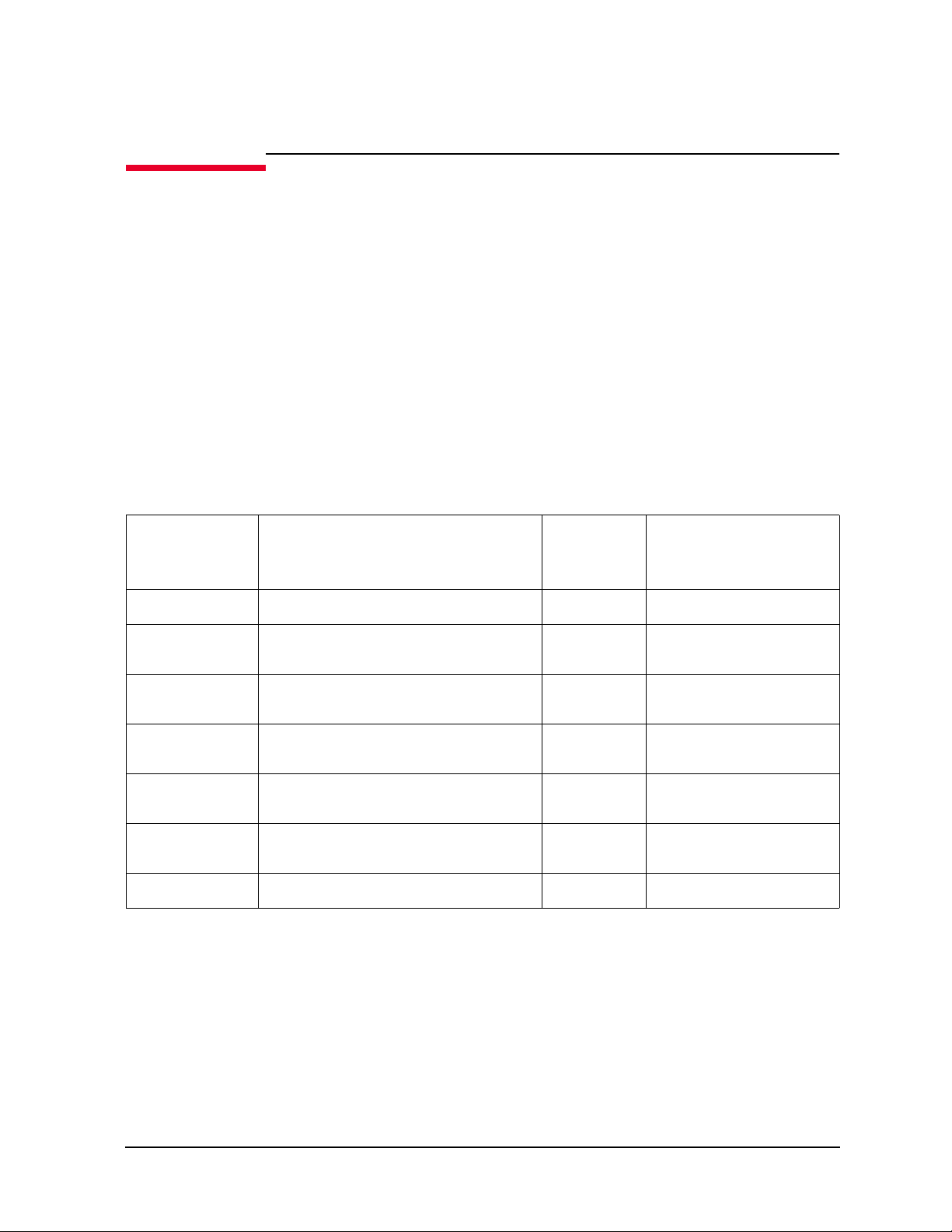
Table 1-1 B1505A Measurement Resource Selection Guide
Measurement Resource Required Module/Expander Main Specification
High Power SMU B1510A HPSMU • Up to 200 V, 1A force
• 10 fA current resolution
Medium Power SMU B1511B MPSMU • Up to 100 V, 100 mA force
• 10 fA current resolution
High Current SMU B1512A HCSMU • 20 A/20 V (Pulsed); 1A/40 V (DC)
High Voltage SMU B1513C HVSMU • 1500 V/8 mA;3000 V/4 mA (Pulsed &
DC)
Medium Current SMU B1514A MCSMU • 1 A/30 V (Pulsed); 100 mA/30 V (DC)
Ultra High Current Unit N1265A Ultra High Current
Expander/Fixture and two units
of B1514A MCSMU/B1512A
HCSMU
High Voltage Medium
Current Unit
Ultra High Voltage Unit N1268A Ultra High Voltage
Multi Frequency CMU B1520A MFCMU • 1 kHz to 5 MHz
N1266A HVSMU Current
Expander, B1513C HVSMU
and two units of B1514A
MCSMU/B1512A HCSMU
Expander and two units of
B1514A MCSMU or a
combination of a B1512A
HCSMU and a B1514A
MCSMU
• 1500 A/60 V (Pulsed), 22.5 kW peak
power
• 500 A/60 V (Pulsed), 7.5 kW peak power
• 1500 V / 2.5 A (Pulsed), 2200 V/ 1.1 A
(Pulsed)
• 10 kV/20 mA (Pulsed);10 kV/10 mA
(DC)
•0 to ±25 V using internal DC bias
•0 to± 3000 V using HVSMU and High
Voltage Bias-Tee
1-4 Keysight B1505A Configuration and Connection Guide
Page 13
B1505A Mainframe Furnished Accessories
The B1505A is furnished with the accessories listed in the following tables. Table 1-2 lists
the accessories for the B1505A mainframe. And Table 1-3 lists the measurement cables
available for and furnished with the plug-in modules. Number of the furnished cables
depends on the number of modules installed in the mainframe.
Table 1-2 Furnished Accessories
Description Qty. Description Qty.
Configuration Guide
B1505A Mainframe Furnished Accessories
16493J Interlock
1
cable
16444A-001 USB
keyboard
16444A-003 Stylus
pen
Description Qty. Note
License sheet 1 License-to-use for Desktop EasyEXPERT Standard edition
Label 1 The label is used to specify the SMU number. Only for the B1505A installed with
1
1 16444A-002 USB
1
SMU.
16493L GNDU
1
cable
mouse
1
1
Power cable 1
1. Cable length 1.5 m or 3.0 m is specified by B1505A cable length option (B1505A-015 or -030).
Keysight B1505A Configuration and Connection Guide 1-5
Page 14
Configuration Guide
B1505A Mainframe Furnished Accessories
Table 1-3 Measurement Cable Furnished with Modules
Description Quantity
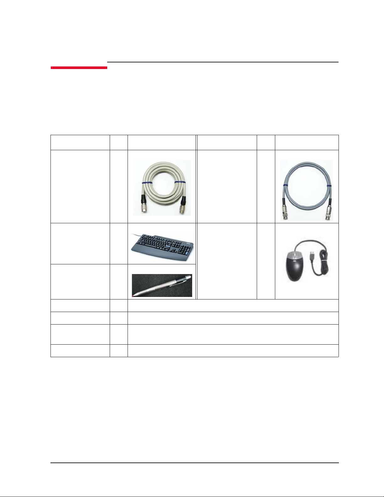
16494A Triaxial cable, for MPSMU, HPSMU and
MCSMU
16493T HVSMU cable, for HVSMU 1 ea./
16493S HCSMU cable, for HCSMU 1 ea./
2 ea./
module
module
module
16493S-010 HCSMU Kelvin adapter, for HCSMU 1 ea./
module
N1300A CMU cable, for MFCMU 1 ea./
module
1-6 Keysight B1505A Configuration and Connection Guide
Page 15
B1505A Modules and Mainframe Options
The B1505A can contain several combinations of modules; up to four dual-slot HPSMU
modules, up to ten MPSMU, up to two dual-slot HCSMU modules, up to five dual-slot
HVSMU, up to six MCSMU and one single-slot MFCMU.
• Select the modules to be installed in the B1505A mainframe
See T able 1-4 for the plug-in modules supported by the B1505A.
• Specify cable length, 1.5 m or 3 m
See T able 1-5 for the options available for the B1505A.
• Select power line frequency, paper manual, rack mount kit, service options, and so on
See T able 1-5 for the options available for the B1505A.
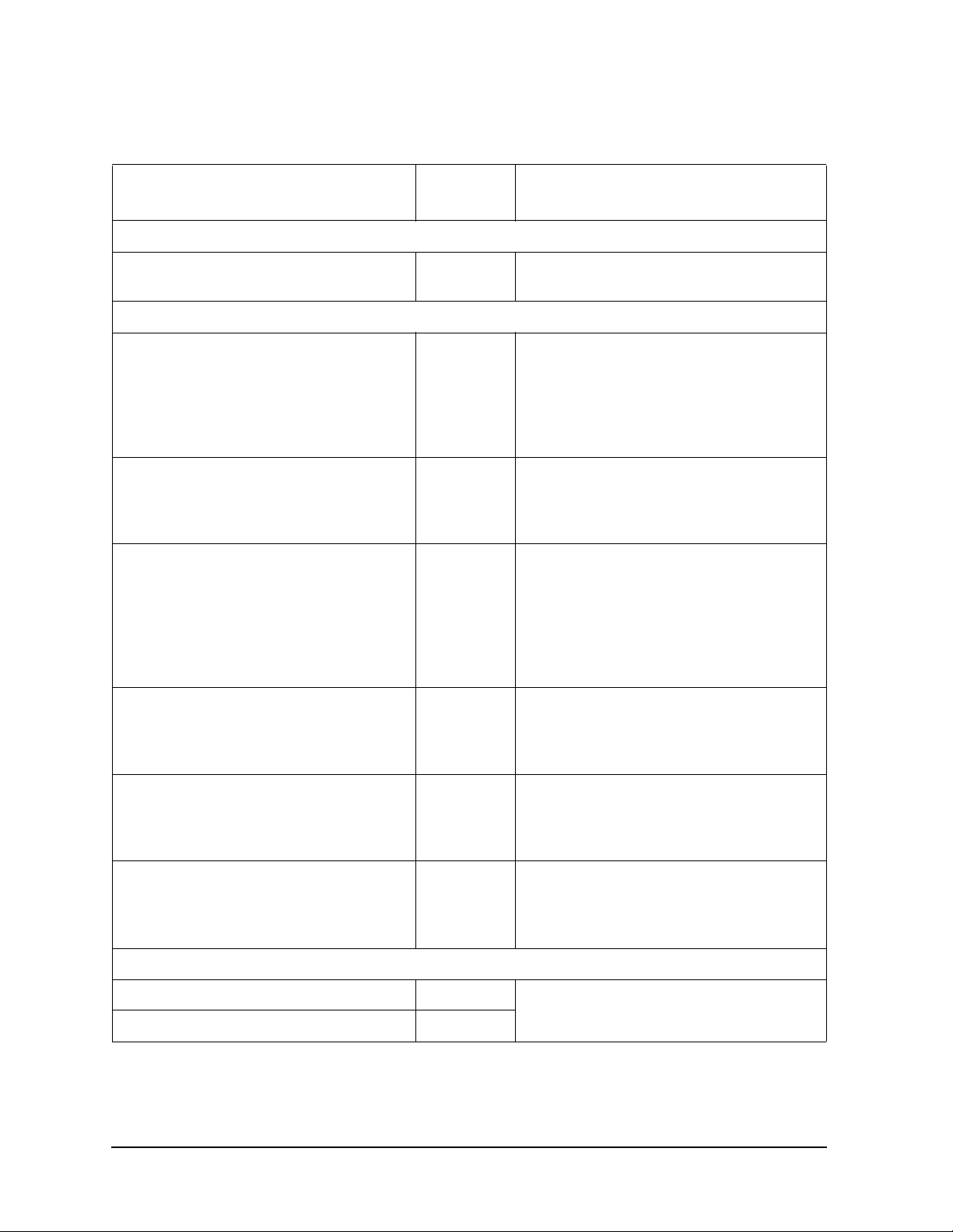
Table 1-4 Plug-in Modules Supported by B1505A
Configuration Guide
B1505A Modules and Mainframe Options
Maximum number of
modules installed in
B1505A
Module type Description
HPSMU
1
High Power Source/Monitor Unit module 2 4
MPSMU Medium Power Source/Monitor Unit
Slots
occupied
110
module
HCSMU
1, 2
High Current Source/Monitor Unit
22
module
HVSMU
3
High Voltage Source/Monitor Unit
25
module
MCSMU Medium Current Source Monitor Unit
16
module
MFCMU Multi Frequency Capacitance
11
Measurement Unit module
GNDU
4
Ground Unit --
1. Total number of installed HPSMU and HCSMU modules cannot exceed 4.
2. Dual HCSMU (DHCSMU) configuration is available if two HCSMU modules are installed in one
mainframe and connected to the 16493S-020 Dual HCSMU Kelvin adapter or the 16493S-021 Dual
HCSMU adapter. This configuration expands the maximum current up to ± 40 A (pulse), ± 2 A (DC).
3. For B1513C only. Multiple B1513A/B1513B HVSMU modules cannot be installed in one mainframe.
4. GNDU has been installed in the mainframe. You do not need to count for the number of slots occupied.
Keysight B1505A Configuration and Connection Guide 1-7
Page 16
Configuration Guide
B1505A Modules and Mainframe Options
Table 1-5 Mainframe Options
Description
Mainframe
Power Device Analyzer/Curve Tracer B1505A • See Table 1-3 on page 1-6 for furnished
Select modules (optional)
High Power Source/Monitor Unit module
(HPSMU), 200 V/1 A
Medium Power Source/Monitor Unit module
(MPSMU), 100 V/100 mA
High Current Source/Monitor Unit module
(HCSMU), 20 A at 20 V
Model/
Option
accessories
B1510A-FG • Furnished with two triaxial cables
(16494A). Cable length 1.5 m or 3.0 m is
specified by 015 or 030.
• Up to four modules can be installed.
• The total number of installed HPSMU and
HCSMU modules cannot exceed 4.
B1511B-FG • Furnished with two triaxial cables
(16494A). Cable length 1.5 m or 3.0 m is
specified by 015 or 030.
• Up to ten modules can be installed.
B1512A-FG • Furnished with one pair of high current
cables (16493S) and Kelvin adapter
(16493S-010). Cable length 1.5 m or 3.0 m
is specified by 015 or 030.
• Up to two modules can be installed.
• The total number of installed HPSMU and
HCSMU modules cannot exceed 4.
Note
High Voltage Source/Monitor Uni t module
(HVSMU), 3000 V at 4 mA
Medium Current Source Monitor Unit
module (MCSMU), 1 A at 30 V
Multi Frequency Capacitance Measurement
Unit module (MFCMU)
Specify the cable length (mandatory)
1.5m cable 015 • Same cable length is applied to all
3.0m cable 030
B1513C-FG • Furni sh ed with one HVSMU cable
(16493T). Cable length 1.5 m or 3.0 m is
specified by option 015 or 030.
• Up to five modules can be installed.
B1514A-FG • Furnished with two triaxial cables
(16494A). Cable length 1.5 m or 3.0 m is
specified by 015 or 030.
• Up to six modules can be installed.
B1520A-FG • Furnished with one CMU cable (N1300A).
Cable length 1.5 m or 3.0 m is specified by
option 015 or 030.
• Up to one modules can be installed.
furnished cables.
1-8 Keysight B1505A Configuration and Connection Guide
Page 17
Configuration Guide
B1505A Modules and Mainframe Options
Description
Specify the power line frequency (mandatory)
50Hz line frequency 050
60Hz line frequency 060
Select calibration options (optional)
ANSI Z540 compliant calibration A6J
Commercial calibration certificate with test
data
Specify the language of the paper manuals if you need
Paper manual set, English ABA • Printed manuals are optional. Order this
Paper manual set, Japanese ABJ
Select rack mount kit (optional)
Rack mount kit 1CM
Model/
Option
UK6
Note
option to get the paper manuals. It contains
B1505A user guide, quick start guide, and
self-paced training manual, EasyEXPERT
user guide and self-paced training manual,
and B1500 series programming guide.
Module type and locations
Module locations when the B1505A is shipped from the factory are shown in Table 1-6 on
page 1-10. This table shows the relative locations by the module types.
If HPSMUs are installed, the HPSMUs must be installed in the slots from the slot number
1. And if HPSMU and MPSMU and MFCMU are not installed and MCSMUs are installed,
the MCSMUs must be installed in the slot number 1. Then the same type of modules must
be installed in the contiguous slots.
For example, if the module configuration is one MFCMU, three MCSMUs, one HCSMU
and one HVSMU, the B1505A will be shipped with the MFCMU of the slot 1, the
MCSMUs of the slot 2 to 4, the HCSMU of the slot 5 to 6, the HVSMU of the slot 7 to 8,
and the blank panels of the slot 9 to 10.
Keysight B1505A Configuration and Connection Guide 1-9
Page 18
Configuration Guide
B1505A Modules and Mainframe Options
Table 1-6 Module Installation Rule in the Factory
Slot Number and Location SMU type and port number
10
:
:
:
:
:
:
:
1
0 bottom GNDU/ADC (Always installed)
NOTE After module installation at Keysight Service Center, the B1505A will be returned with the
module configuration defined by the rule shown in the T able 1-6 . If you want to change the
module locations, consult the service personnel before servicing.
top
:
:
:
:
:
:
:
:
B1513A/B/C High Voltage SMU (HV SMU )
B1512A High Current SMU (HCSMU)
B1514A Medium Current SMU (MCSMU)
B1520A Multi Frequency CMU (MFCMU)
B1511A/B Medium Power SMU (MPSMU)
B1510A High Power SMU (HPSMU)
1-10 Keysight B1505A Configuration and Connection Guide
Page 19
Configuration Guide
N1259A Test Fixture for Power Device
N1259A Test Fixture for Power Device
The N1259A is a test fixture used for package device measurements. It supports up to 3 kV
and 40 A. The following table lists the accessories available for the N1259A test fixture.
Select the required accessories. If you add options later, please refer to "Upgrade Kit for
N1259AU Test Fixture" on page 1-65.
Table 1-7 N1259A Test Fixture options and accessories
Model/Option Description Additional Information
N1259A Test Fixture for Power Device • N1259A-001 is a mandatory option.
Please select options that meet your
needs.
N1259A-001 Test Fixture for Power Device • Mandatory option
• The N1259A-001 is furnished with
Kelvin socket module for inline package
device (N1259A-010), four black
connection wires (N1259A-509) and six
red connection wires (N1259A-508).
• The N1259A-001 has a built-in GNDU
protection adapter and a built-in HPSMU
protection adapter inside.
Keysight B1505A Configuration and Connection Guide 1-11
Page 20

Configuration Guide
N1259A Test Fixture for Power Device
Model/Option Description Additional Information
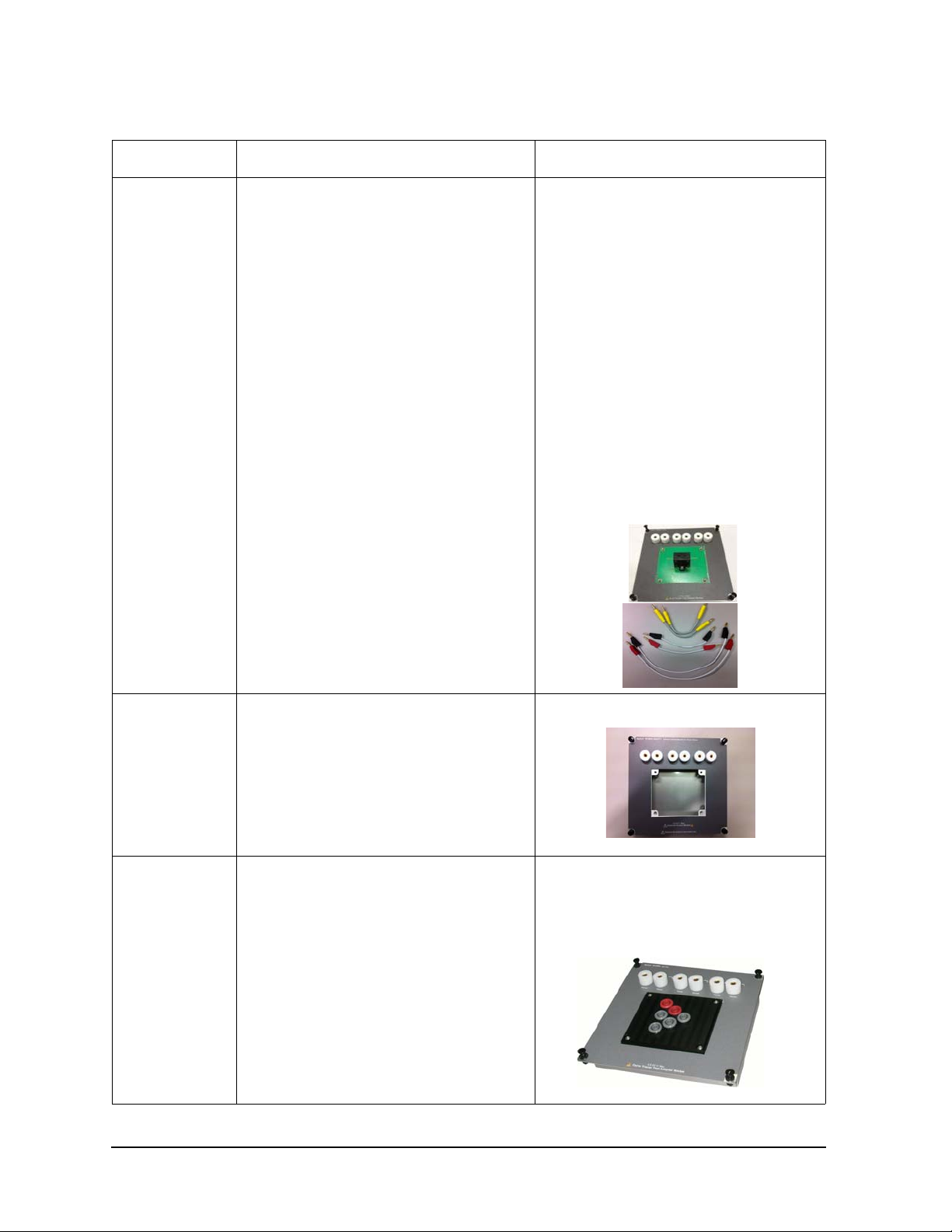
N1259A-010 Inline Package Socket Module (3 pin) • The N1259A-001 Test Fixture for Power
Device is furnished with a N1259A-010
socket module.
• The N1259A-010 cannot be used with the
N1265A Ultra High Current Expander /
Fixture.
• Max voltage and current are 3 kV and 40
A.
N1259A-011 Universal socket module for power device • Maximum voltage is 3 kV.
N1259A-012 Blank PTFE board
N1259A-013 Curve tracer test adapter socket module • The N1259A-013 is the same as the
N1265A-013 Curve Tracer Test Adapter
Socket Module.
• Maximum voltage and current is 3 kV and
500 A.
1-12 Keysight B1505A Configuration and Connection Guide
Page 21
Configuration Guide
Collector / Drain
Emier / Source Base / Gate
N1259A Opt 013
Force Sense
Force Sense
Force Sense
Curve Tracer Test Adapter Socket
1
2
5
6
4
3
A
BC
59
N1259A Test Fixture for Power Device
Model/Option Description Additional Information
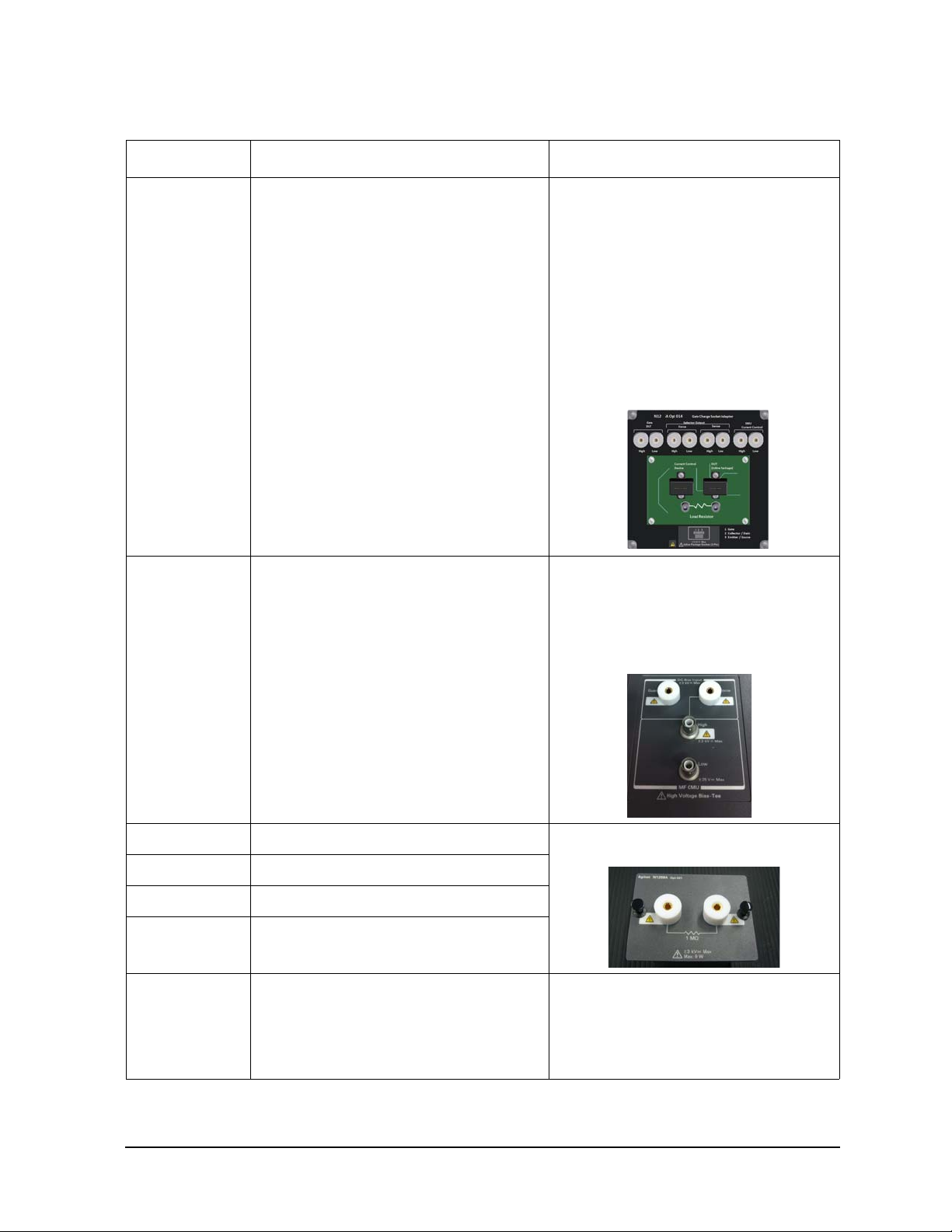
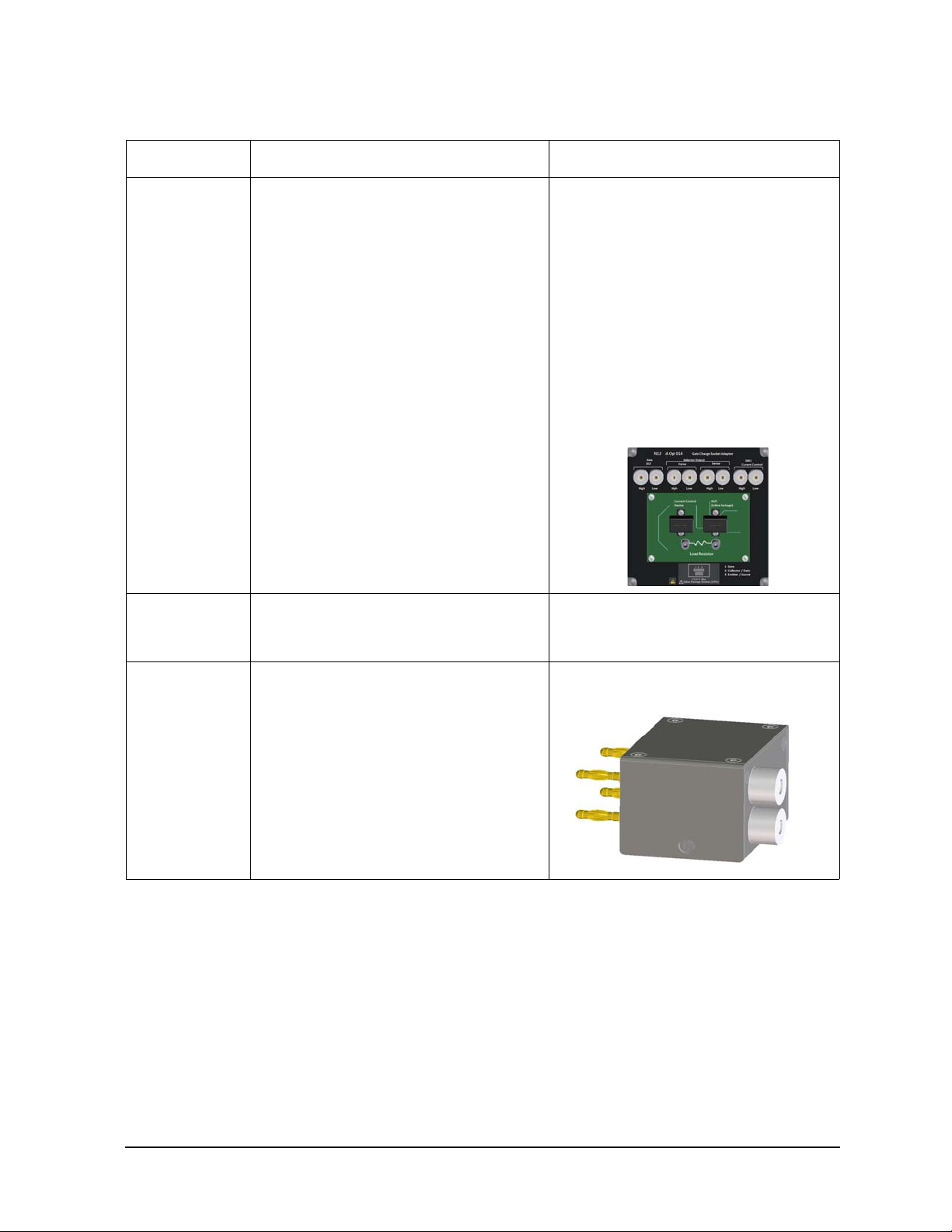
N1259A-014 Gate charge socket module • The N1259A-014 is the same as the
N1265A-014 Gate Charge Socket
Module.
• The N1259A-014 op tion is furnishe d with
the following wires:
- Four red long wires (N1254A-508)
- Four black long wires (N1254A-509)
- Two red short wires (N1265-61751)
- Two black long wires (N1265-61752)
• Maximum voltage and current is 3 kV and
20 A.
N1259A-020 High V oltage Bias-T ee • The N1259A-020 option i s furnished with
two SHV -SHV cables (N1254A-512) and
two SHV-banana adapters (N1254A-513).
• The N1259A-020 is a built-in
factory-installed accessory of the
N1259A-001.
N1259A-021 1 M R-box • R-box can be replaced with other R-box
easily by N1259A users.
N1259A-022 100 k R-box
N1259A-030 1 k R-box
N1259A-035 U niversal R-box
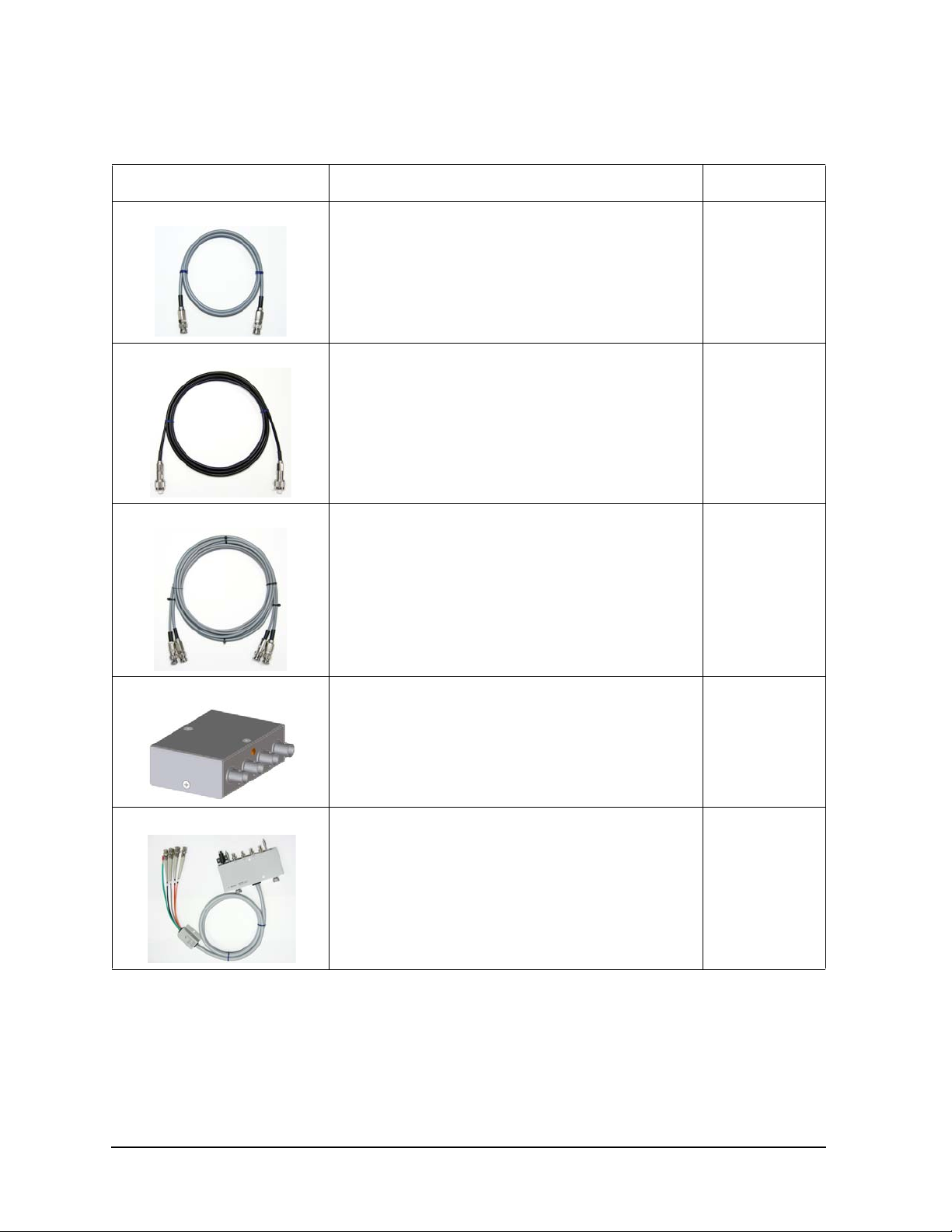
N1259A-300 Module Selector • Furnished with a 1.5 m digital I/O control
cable (16493G-001), maximum 35VA
• The N1259A-300 is a built-in and
factory-installed option for the
N1259A-001.
Keysight B1505A Configuration and Connection Guide 1-13
Page 22
Configuration Guide
N1259A Test Fixture for Power Device
Model/Option Description Additional Information
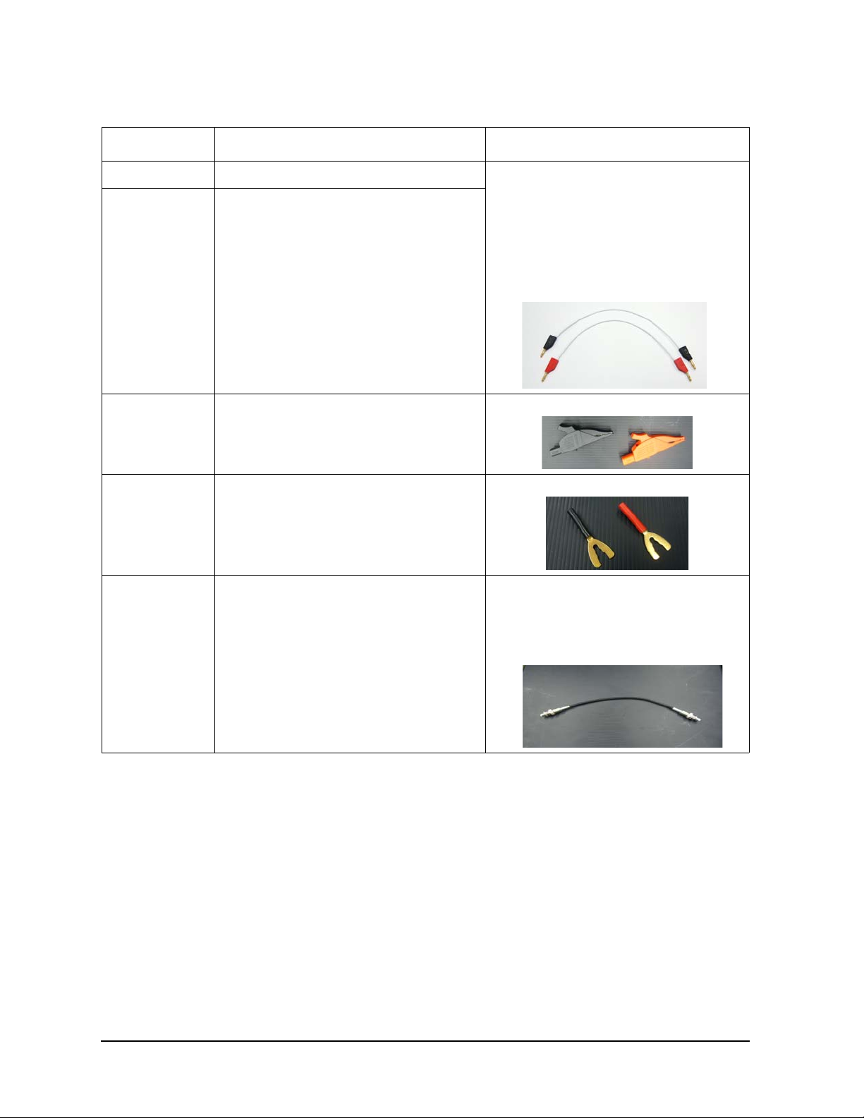
N1254A-508 Connection wire, red 1 ea. • The N1254A-508/509 Connection Wire
N1254A-509 Connection wire, black 1 ea.
N1254A-510 Dolphin clip adapter, black 1 ea. and red 1ea.
supports 40A current, but does not
support 500 A/1500 A current flow on the
N1265A Ultra High Current
Expander/Fixture.
• Maximum voltage and current is 3 kV and
40 A.
• The cable length is 250 mm.
N1254A-511 Cable lug adapter, black 1 ea. and red 1ea.
N1254A-512 SHV to SHV cable 350 mm, 1 ea. • The N1259A-020 High Voltage Bias-tee
is furnished with two N1254A-512
cables.
• The N1254A-513 adapter is required to
connect the banana plug.
1-14 Keysight B1505A Configuration and Connection Guide
Page 23
Configuration Guide
N1259A Test Fixture for Power Device
Model/Option Description Additional Information
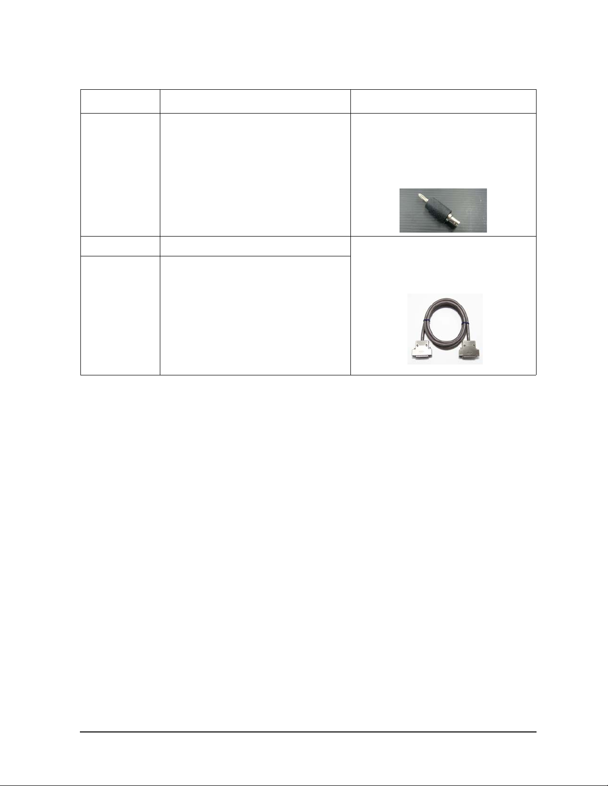
N1254A-513 SHV to banana adapter, 1 ea. • The N1259A-020 High Voltage Bias-tee
is furnished with two N1254A-513
adapters.
• An N1254A-513 adapter is used with an
N1254A-512 cable to connect a banana
plug.
16493G-001 Digital I/O control cable (1.5 m) • The N1259A-300 Module Selector option
16493G-002 Digital I/O control cable (3.0 m)
is furnished with a 16493G-001 cable.
• Cable length 1.5 m or 3.0 m can be
specified by option 001 or 002.
Keysight B1505A Configuration and Connection Guide 1-15
Page 24
Configuration Guide
N1259A Test Fixture for Power Device
Model/Option Description Additional Information
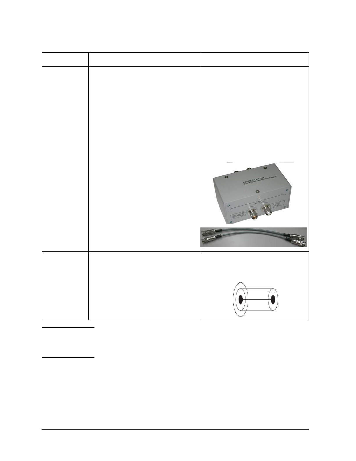
16493S-021 Dual HCSMU combination adapter, for 40 A
measurement
• Output connectors are compatible with
B1512A HCSMU.
• The 16493S-021 is furnished with one
30cm Triaxial cable and one 30 cm High
current coaxial cable for output
connection.
• Do not connect or put any conductor on
the HCSMU Low Force and Low Sense
terminals, outer conductor of the coaxial
connectors. Connecting or locating
conductor of circuit common, chassis
ground, or any potential on causes the
measurement error.
N1254A-104 Triax (f) to BNC (m) adapter • This adapter is required when a B1514A
MCSMU is connected to the HCSMU
ports of the N1259A Fixture. This adapter
is used for Force terminal.
NOTE The N1259A-020 high voltage bias-T and/or the N1259A-300 module selector can be
installed in the N1259A-001 test fixture later. For upgrade kit, please refer to "Upgrade Kit
for N1259AU Test Fixture" on page 1-65. Keysight Technologies service center is
responsible for N1259AU-020 and N1259AU-300 installation.
1-16 Keysight B1505A Configuration and Connection Guide
Page 25
Configuration Guide
N1265A Ultra High Current Expander/Fixture
N1265A Ultra High Current Expander/Fixture
The N1265A expands the B1505A’s current capability up to 1500 A. Current expansion is
made using the Ultra High Current Unit (UHCU), which is comprised of a current
expander in the N1265A and two MCSMUs which are connected to I/V control ports of the
N1265A. The MCSMU used for the I/V controller can be substituted by the HCSMU.
The following table lists the accessories available for the N1265A Ultra High Current
Expander/Fixture. Select the required accessories. If you add options later, please refer to
"Upgrade Kit for N1265AU Test Fixture" on page 1-69.
Table 1-8 Options and accessories for N1265A Ultra High Current Expander/Fixture
Model/Option Description Additional Information
N1265A Ultra High Current Expander/Fixture • The N1265A-001 is a mandatory option
for the N1265A. Please select options that
meet your needs.
• The N1265A UHC Expander/Fixture
does NOT have a built-in Bias-Tee option
like the N1259A Test Fixture. The
N1260A High Voltage Bias-Tee is
necessary for capacitance measurement.
N1265A-001 Ultra High Current Expander/Fixture • Mandatory option
• A 500A current amplifier and a built-in
module selector are included mandatorily.
• The N1265A-001 is furnished with a 1.5
m Digital I/O control cable
(16493G-001), a Blank Silicon Plate and
a power code.
Keysight B1505A Configuration and Connection Guide 1-17
Page 26
Configuration Guide
N1265A Ultra High Current Expander/Fixture
Model/Option Description Additional Information
N1265A-010 500 A Ultra High Current 3-pin Inline Package
Socket Module
• The N1265A-010 is furnished with total
six cable shown below
• N1252A-522 1500A Ultra High
Current Banana to Banana Cables
(Yellow, 2ea) for Collector/Drain and
Emitter/Source force lines
• N1265-61751 Test Lead (Banana),
180mm (Red, 1ea) and N1265-61752
Test Lead (Banana), 180mm (Black,
1ea.) for Collector/Drain and
Emitter/Source sense lines
• N1254A-508 Banana to Banana
cable, 250mm (Red, 1ea),
N1254A-509 Banana to Banana
cable, 250mm (Black, 1ea) for
Base/Gate force/sense lines
• Maximum voltage and current is 3 kV and
500 A.
N1265A-011 Universal socket module for power device • Maximum voltage is 3 kV.
N1265A-013 Curve tracer test adapter socket module • The N1265A-013 is the same as the
N1259A-013 Curve Tracer Test Adapter
Socket Module.
• Maximum voltage and current is 3 kV and
500 A.
1-18 Keysight B1505A Configuration and Connection Guide
Page 27
Configuration Guide
Collector / Drain
Emier / Source Base / Gate
N1259A Opt 013
Force Sense
Force Sense
Force Sense
Curve Tracer Test Adapter Socket
1
2
5
6
4
3
A
BC
59
N1265A Ultra High Current Expander/Fixture
Model/Option Description Additional Information
N1265A-014 Gate charge socket module • The N1265A-014 is the same as the
N1259A-014 Gate Charge Socket
Module.
• The N1265A-014 option is furnished
with:
- Four red long wires (N1254A-508)
- Four black long wires (N1254A-509)
- Two red short wires (N1265-61751)
- Two black long wires (N1265-61752)
- Two yellow high current banana-banana
cable (N1254A-522)
• Maximum voltage and current is 3 kV and
500 A.
N1265A-015 1500 A Current Option • 1500 A upgrade can be made later by
ordering a B1505AU-015 1500 A
upgrade kit.
N1265A-035 Universal R-Box • A desired register can be installed by
soldering.
Keysight B1505A Configuration and Connection Guide 1-19
Page 28
Configuration Guide
N1265A Ultra High Current Expander/Fixture
Model/Option Description Additional Information
N1265A-040 10 kV Ultra High Voltag e Gate Protection
Adapter
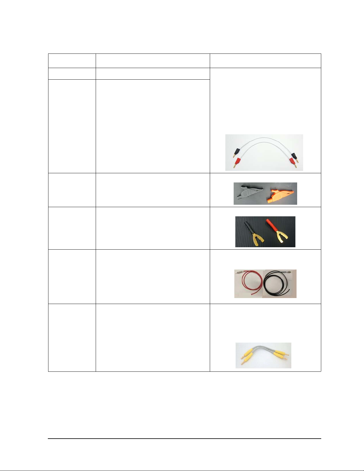
N1265A-041 Thermocouple, Type K, 2ea • Include two Type-K thermocouples
N1265A-045 Container for Protection Adapter and Bias Tee • An N1260A High Voltage Bias-tee and
• This adapter is used to protect a B1514A
MCSMU module used for a Gate driver
from device breakdown when making
ultra high voltage measurement with the
N1268A UHV Expander
• The B1514A MCSMU module has to be
connected to a passthrough port of the
N1265A UHC Expander/Fixture, not a
module selector port.
N1261A Protection Adapters can be
placed in this container to avoid messy
cabling.
Calibration options
N1265A-A6J ANSI Z540 compliant calibration
N1265A-UK6 Commercial cal. Certificate with test data
Connection accessories inside the N1265A
1-20 Keysight B1505A Configuration and Connection Guide
Page 29
Configuration Guide
N1265A Ultra High Current Expander/Fixture
Model/Option Description Additional Information
N1254A-508 Connection wire, red 1 ea. • Max voltage and current are 3 kV and 40
N1254A-509 Connection wire, black 1 ea.
N1254A-510 Dolphin clip adapter, black 1 ea. and red 1ea.
A.
• The N1254A-508/509 Connection wire
does not support 500A/1500A current
flow on the N1265A Ultra High Current
Expander/Fixture. Use the N1254A-522
1500A Ultra High Current Banana to
Banana cable.
• Cable length is 250 mm.
N1254A-511 Cable lug adapter, black 1 ea. and red 1ea.
N1254A-520 10 kV Ultra High Vo ltage Open End Cable, 1 m.• One-side 10kV UHV/SHV and the
other-side open end
N1254A-522 1500 A Ultra High Current Banana to Banana
Cable, 2 ea.
• Max voltage and current are 3 kV and
1500 A.
• The N1265A-010 500 A Ultra High
Current 3-pin Inline Package Socket
Module is furnished with these cables.
Keysight B1505A Configuration and Connection Guide 1-21
Page 30
Configuration Guide
N1265A Ultra High Current Expander/Fixture
Model/Option Description Additional Information
N1254A-523 1500 A Ultra High Current Banana to Open
End Cable, 1 m, 2 ea
16493G-001 Digital I/O control cable (1.5 m) • The N1265A-001 is furnished with a
16493G-002 Digital I/O control cable (3.0 m)
For capacitance measurement
N1260A High V oltage Bias-T ee • The N1265A does not have a built-in high
• Max voltage and current are 3 kV and
1500 A.
16493G-001 cable.
• Cable length 1.5 m or 3.0 m can be
specified by option 001 or 002.
voltage bias-tee option like the N1259A.
The N1260A is required to make
capacitance measurement with the
N1265A.
• The N1260A-STD is a mandatory option.
• The N1260A High Voltage Bias-Tee is
not furnished with any cables.
N1254A-512 SHV to SHV cable 350mm, 1 ea. • The N1254A-513 SHV Jack to Banana
Adapter is required to connect a banana
plug.
1-22 Keysight B1505A Configuration and Connection Guide
Page 31

Configuration Guide
N1265A Ultra High Current Expander/Fixture
Model/Option Description Additional Information
N1254A-513 SHV to banana adapter, 1 ea. • The N1254A-513 adapter is used with the
N1254A-512 cable to connect the banana
plug.
N1254A-518 SHV Cable 1.5 m, 1 ea
Adapters
N1254A-103 Triaxial (m) to BNC (f) adapter • This adapter is needed when a B1512A
HCSMU is connected to a voltage/current
controller SMU port or Gate port o r SMU
ports of the N1265A. This adapter is used
for Force terminal.
N1254A-517 Adapter, Triax Jack to Triaxial Plug • This adapter is needed when a B1512A
HCSMU is connected to a voltage/current
controller SMU port or Gate port o r SMU
ports of the N1265A. This adapter is used
for Sense terminal.
Keysight B1505A Configuration and Connection Guide 1-23
Page 32

Configuration Guide
N1265A Ultra High Current Expander/Fixture
Model/Option Description Additional Information
For on-wafer measurement
N1254A-524 500 A Ultra High Current Prober System
Cable
NOTE The N1259A-010 Inline Package Module (3 pin) and N1259A-011 Universal Socket
Module cannot be used with the N1265A Ultra High Current Expander/Fixture.
• The N1254A-524 cable is furnished with
one transparent shield with a slit.
• Maximum current range is about 800 A or
more.
• Cable length is 1.8 m.
1-24 Keysight B1505A Configuration and Connection Guide
Page 33

Configuration Guide
N1266A High Voltage Source Monitor Unit Current Expander
N1266A High Voltage Source Monitor Unit Current
Expander
The N1266A expands HVSMU current up to 2.5 A. Current expansion is made using the
High Voltage Medium Current Un it (HVMCU), which is comprised of N1266A, HVSMU
(B1513A, B, or C) and two MCSMUs which are connected to I/V control ports of the
N1266A. The MCSMU used for the I/V controller can be substituted by the HCSMU.
The following table lists the accessories available for the N1266A High Voltage Source
Monitor Unit Current Expander. Select the required accessories.
Table 1-9 Accessories for N1266A Ultra High Current Expander/Fixture
Model/Option Description Additional Information
N1266A High Voltage Source Monitor Unit Current
Expander
Calibration options
N1266A-A6J ANSI Z540 compliant calibration
N1266A-UK6 Commercial cal. Certificate with test data
• The N1266A is furnished with 1.5 m
Digital I/O control cable (16493G-001)
and a power code.
• The N1266A does not include a 16493T
High Voltage Source Monitor Unit Cable
and a 16493L GNDU Cable. Order a
16493T-001/002 and a 16493L-001/002
separately.
Keysight B1505A Configuration and Connection Guide 1-25
Page 34

Configuration Guide
N1266A High Voltage Source Monitor Unit Current Expander
Model/Option Description Additional Information
Related cables
16493G-001 Digital I/O control cable (1.5 m) • The N1266A is furnished with a
16493G-002 Digital I/O control cable (3.0 m)
16493L-001 Ground Unit Cable (Triaxial, 1.5 m) • Cable length 1.5 m or 3.0 m can be
16493L-002 Ground Unit Cable (Triaxial, 3.0 m)
16493G-001 cable.
• Cable length 1.5 m or 3.0 m can be
specified by option 001 or 002.
specified by option 001 or 002.
16493T-001 High Voltage Source Mon itor Unit Cable (1.5 m)• The 16493T-001/002 supports up to
3000V.
16493T-002 High Voltage Source Mon itor Unit Cable (3.0
m)
• Cable length 1.5 m or 3.0 m can be
specified by option 001 or 002.
1-26 Keysight B1505A Configuration and Connection Guide
Page 35

Configuration Guide
N1266A High Voltage Source Monitor Unit Current Expander
Model/Option Description Additional Information
Adapters
N1254A-103 Triaxial (m) to BNC (f) adapter • This adapter is needed when a B1512A
HCSMU is used as a voltage/current
controller of the N1266A instead of
MCSMU. This adapter is used for Force
terminal.
N1254A-517 Adapter, Triax Jack to Triaxial Plug • This adapter is needed to use a B1512A
HCSMU as a voltage/current controller of
the N1266A instead of MCSMU. This
adapter is used for Sense terminal.
N1266A Compatibility with Fixture and Module Selector
The N1266A can be used with the N1265A Ultra High Current Test Fixture, N1259A Test
Fixture for Power Device and N1258A Module Selector for B1505A. Table 1-10 shows the
equipment list which is compatible with the N1266A for package device testing and
on-wafer device testing environment.
Table 1-10 N1266A Compatibility with Fixture and Module Selector
Test Environment Supported Fixture and Module Selector
Package device testing • N1259A Test Fixture for Power Device with or without
N1259A-300 Module Selector Option
• N1265A Ultra High Current Expander/Fixture
On-wafer device testing • N1265A Ultra High Current Expander/Fixture with a
N1254A-524 Ultra High Current Prober System Cable
• M1258A Module Selector
Keysight B1505A Configuration and Connection Guide 1-27
Page 36

Configuration Guide
N1266A High Voltage Source Monitor Unit Current Expander
Figure 1-2 N1266A Compatibility with Fixture and Module Selector
1-28 Keysight B1505A Configuration and Connection Guide
Page 37

Configuration Guide
N1267A High Voltage Source Monitor Unit / High Current Source Monitor Unit Fast Switch
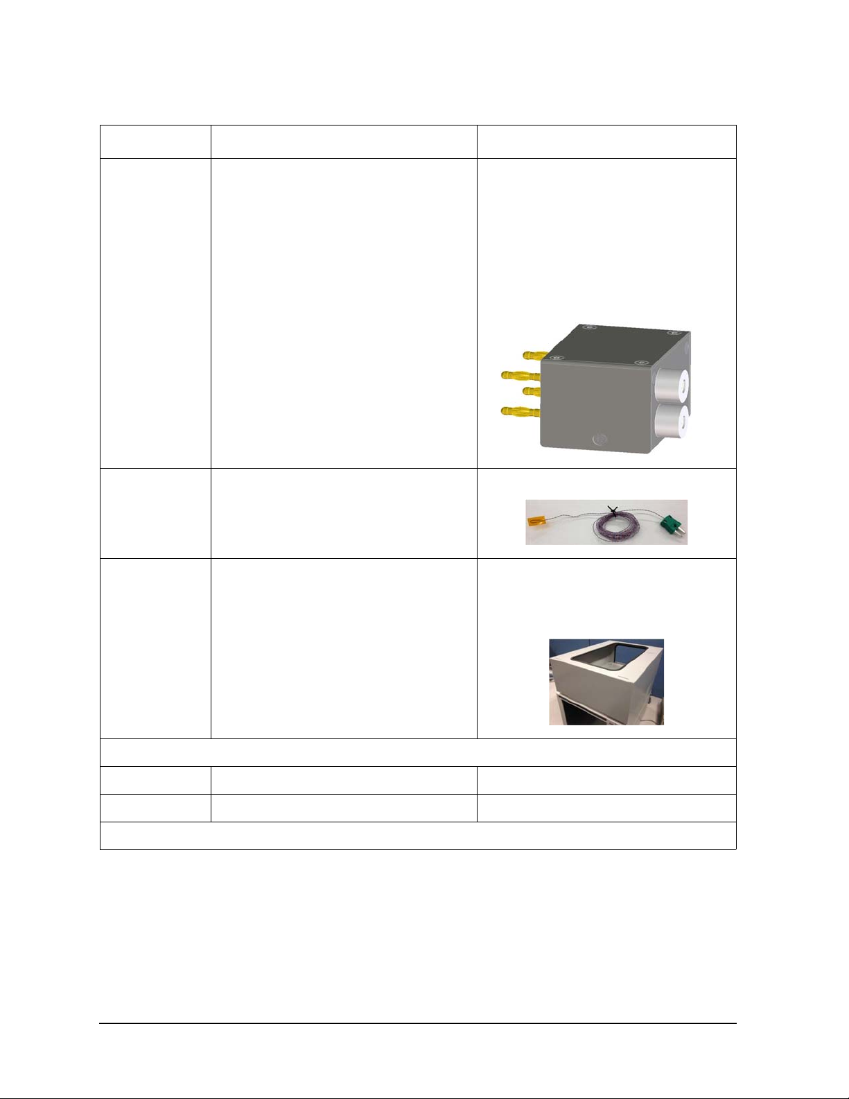
N1267A High Voltage Source Monitor Unit / High
Current Source Monitor Unit Fast Switch
The N1267A supports fast switching between the HVSMU and HCSMU to enable the
measurement of the GaN current collapse phenomena. The N1267A switch requires one
MCSMU in the B1505A mainframe for control. Please refer to Chapter 4 Connection and
Ordering Examples for connection examples for GaN current collapse measurement
system using the N1267A.
Table 1-11 Accessories for the N1267A HVSMU/HCSMU Fast Switch
Model/Option Description Additional Information
N1267A High Voltage Source Monitor Unit / High
Current Source Monitor Unit Fast Switch
Table 1-12 Supported B1505A modules for the N1267A HVSMU/HCSMU Fast Switch
Drain stress bias SMU at device OFF state • B1513B/C HVSMU (B1513A HVSMU is NOT
supported)
Drain current measurement SMU at device ON state • B1512A HCSMU
N1267A control SMU • B1514A MCSMU
Gate control SMU • B1514A MCSMU
• B1512A HCSMU
• B1510A HPSMU and B1511A/B MPSMU are NOT
supported as a gate control SMU.
• The N1267A is NOT furnished with any
cable.
Supported B1505A modules
Substrate bias SMU • B1510A HPSMU
• B1511A/B MPSMU
• B1512A HCSMU
• B1514A MCSMU
Keysight B1505A Configuration and Connection Guide 1-29
Page 38

Configuration Guide
N1267A High Voltage Source Monitor Unit / High Current Source Monitor Unit Fast Switch
Table 1-13 Supported Environment for the N1267A HVSMU/HCSMU Fast Switch
Supported Environment Supported instruments
On-wafer measurement
Package device measurement • N1259A Test Fixture (N1259A-300 Module Selector
option is required for Kelvin connection measurement)
NOTE The N1267A does not support the two HCSMU 40A configuration.
1-30 Keysight B1505A Configuration and Connection Guide
Page 39

Configuration Guide
N1268A Ultra High Voltage Expander
N1268A Ultra High Voltage Expander
The N1268A expands the B1505A’s voltage capability up to 10 kV. Voltage expansion is
made using the Ultra High Voltage Unit (UHVU), which is comprised of N1268A and two
MCSMUs which are connected to I/V control ports of the N1268A. The MCSMU used for
the V controller can be substituted by the HCSMU.
The following table lists the accessories available for the N1268A Ultra High Voltage
Expander. Select the required accessories.
Table 1-14 Options and accessories for N1268A Ultra High Voltage Expander
Model/Option Description Additional Information
N1268A Ultra High Voltage Expander • The N1268A-STD is a mandatory option.
N1268A-STD Ultra High Voltage Expander • Mandatory option
• The N1268A-STD is furnished with a
16493G-001 Digital I/O control cable
(1.5m), a 16493J-001 Interlock cable
(1.5m) and a power code.
• The N1268A-STD is NOT furnished with
a 16493V 10kV Ultra High Voltage
Cable. Order a 16493V-001/002
separately.
Calibration options
N1268A-A6J ANSI Z540 compliant calibration
Keysight B1505A Configuration and Connection Guide 1-31
Page 40

Configuration Guide
N1268A Ultra High Voltage Expander
Model/Option Description Additional Information
N1268A-UK6 Commercial cal. Certificate with test data
Related accessories for package device testing
N1265A-040 10 kV Ultra High Voltag e Gate Protection
Adapter
Related accessories for on-wafer device testing
N1269A Ultra High Voltage Connection Adapter • The N1269A adapter is used to protect
• The N1265A-040 adapter is used with the
N1265A UHC Expander/Fixture for
package device testing.
• This adapter is used to protect a B1514A
MCSMU module used as a Gate driver
SMU from device breakdown when
making ultra high voltage measurement
with the N1268A.
measurement resources from unexpected
surge when connecting the N1268A Ultra
High Voltage Expander to a wafer prober.
• Protection adapter for the B1514A
MCSMU is included in the N1269A
adapter.
• This adapter supports the B1514A
MCSMU only.
1-32 Keysight B1505A Configuration and Connection Guide
Page 41

Configuration Guide
N1268A Ultra High Voltage Expander
Model/Option Description Additional Information
N1262A-023 Universal R-Box for Ultra High Voltage
N1254A-521 10 kV Ultra High Voltage Jack to Jack Adapter • Feed through adapter set of UHV and
SHV connectors
Related cables
16493G-001 Digital I/O control cable (1.5 m) • The N1268A is furnished with a
16493G-002 Digital I/O control cable (3.0 m)
16493G-001 cable.
• Cable length 1.5 m or 3.0 m can be
specified by option 001 or 002.
16493J-001 Interlock cable (1.5 m) • The N1268A is furnished with a
16493J-002 Interlock cable (3.0 m)
16493J-001 cable.
• Cable length 1.5 m or 3.0 m can be
specified by option 001 or 002.
Keysight B1505A Configuration and Connection Guide 1-33
Page 42

Configuration Guide
N1268A Ultra High Voltage Expander
Model/Option Description Additional Information
16493V-001 10 kV Ultra High Voltage Cable, 1.5 m • One UHV cable (Red) and one SHV cable
16493V-002 10 kV Ultra High Voltag e Cable, 3 m
N1254A-520 10 kV Ultra High Vo ltage Open End Cable, 1 m.• One-side 10kV UHV/SHV and the
(Black) are included in the
16493V-001/002.
• These cables are used to connect between
the N1268A UHV Expander and the
N1265A Ultra High Current
Expander/Fixture or a prober.
• Cable length 1.5 m or 3.0 m can be
specified by option 001 or 002.
other-side open end
• These cables are used to connect between
the N1268A UHV output and a device
under test (DUT) placed inside the
N1265A.
Adapters
N1254A-103 Triaxial (m) to BNC (f) adapter • This adapter is needed when a B1512A
HCSMU is used as a voltage controller of
the N1268A. This adapter is used for
Force.
N1254A-517 Adapter, Triax Jack to Triaxial Plug • This adapter is needed when a B1512A
HCSMU is used as a voltage controller of
the N1268A. This adapter is used for
Sense.
NOTE The HPSMU and MPSMU modules cannot be used with the Ultra High Voltage Unit
(UHVU) even when protection adapters are used.
1-34 Keysight B1505A Configuration and Connection Guide
Page 43

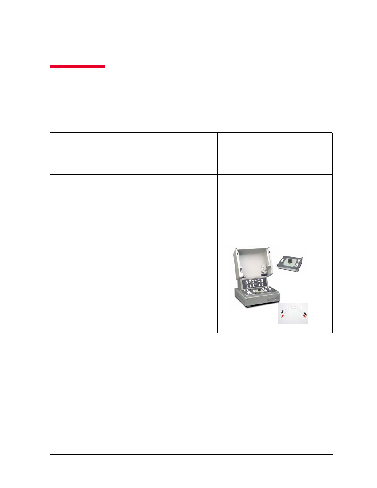
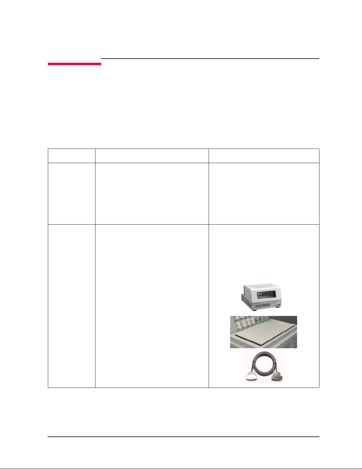
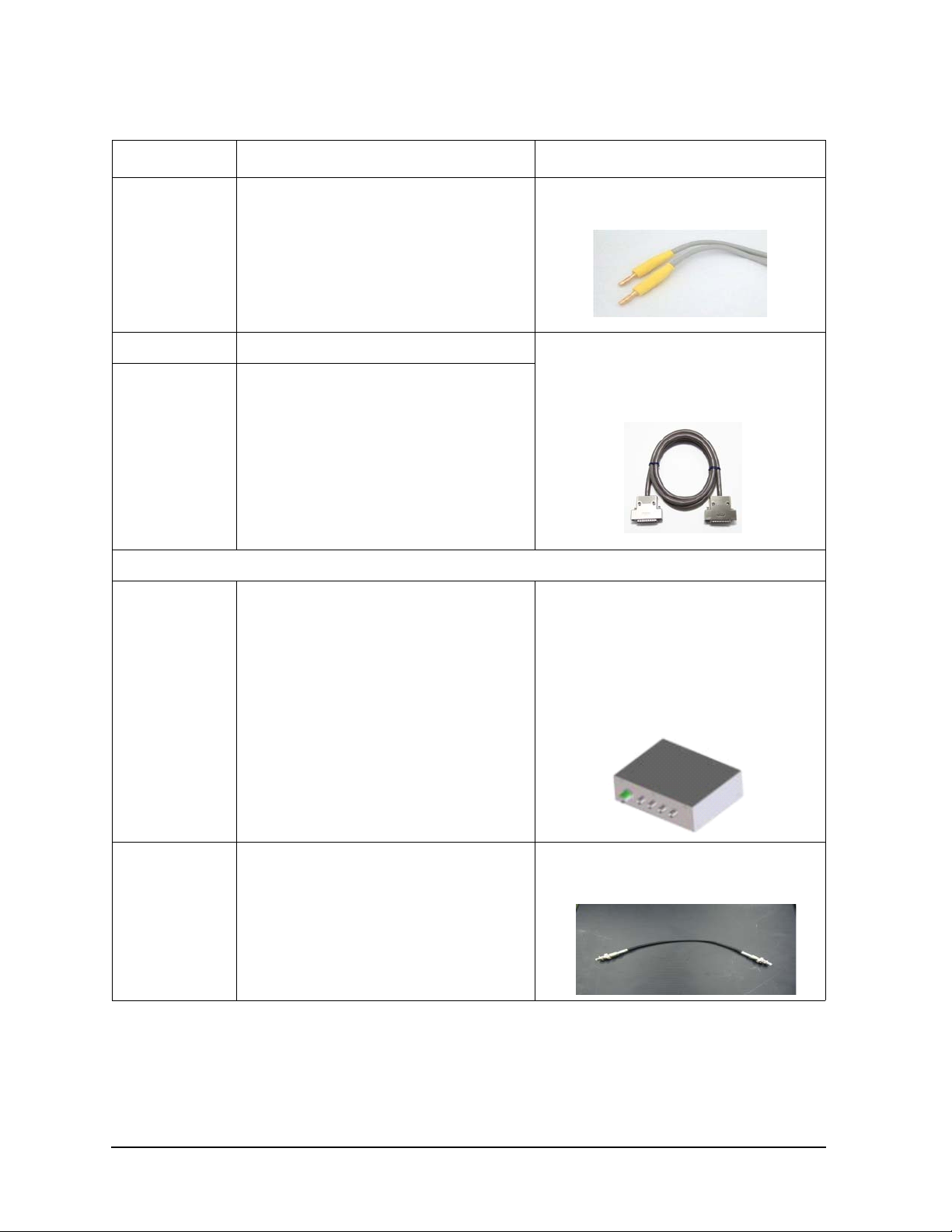
N1271A Thermal Test Enclosure and Related
Thermostream
(inTEST corp.)
㻌
Thermal
Enclosure
㻌
Thermal Plate㻌
(inTEST corp.)
㻌
(a) Using Thermal Plate (b) Using Thermostream
Accessories
The N1271A is an accessory for the N1259A/N1265A fixture and is necessary for
performing the thermal test. The N1271A has three options 001, 002, and 005.
The N1271A-001 is required for using the inTEST thermal plate and can be used with the
N1259A or the N1265A.
The N1271A-002 or 005 is required for using the inTEST Thermostream and can be used
with the N1265A. The N1271A-002 supports the IV measurement up to 3 kV. The
N1271A-005 supports the IV measurement up to 10 kV and the CV measurement up to
3kV.
Figure 1-3 Thermal Test
Configuration Guide
N1271A Thermal Test Enclosure and Related Accessories
Keysight B1505A Configuration and Connection Guide 1-35
Page 44

Configuration Guide
N1271A Thermal Test Enclosure and Related Accessories
Table 1-15 N1271A Thermal Test Enclosure Options and Related Accessories
Model/Option Description Additional Information
N1271A Thermal Test Enclosure
N1271A-001 Thermal Plate Compatible Enclosure for
N1259A/N1265A
N1271A-002 Thermostream Compatible Enclosure for
N1265A (3 kV IV)
• Accessory for the N1259A/N1265A test
fixture for using the inTEST Thermal
Plate to enable temperature dependency
measurements up to +250 C.
• Contains the N1254A-557 connection kit.
• Inner dimension is 284 mm W, 340 mm
H, 195 mm D.
• Interface between the N1265A and the
inTEST Thermostream. The enclosure
supports fully automated IV
measurements up to 3 kV at temperature
range from -50 C to +220 C.
• Contains the N1254A-557 connection kit.
• Inner dimension is 284 mm W, 150 mm
H, 195 mm D.
1-36 Keysight B1505A Configuration and Connection Guide
Page 45

Configuration Guide
N1271A Thermal Test Enclosure and Related Accessories
Model/Option Description Additional Information
N1271A-005 Thermostream Compatible Enclosure for
N1265A (3 kV IV, CV and 10 kV)
N1254A Accessories for instruments and fixtures
N1254A-550 Test Leads and Connection Kit for Thermal
Test, 20 cm
• Interface between the N1265A and the
inTEST Thermostream. The enclosure
supports CV measurements up to 3 kV
and IV measurements up to 10 kV at
temperature range from -50 C to +220
C.
• Contains the N1254A-557 connection kit.
• Inner dimension is 275 mm W, 150 mm
H, 195 mm D.
Connection kit, thermal resistance up to +250
C
This kit contains the following items.
• 200 mm high current cable, 2 ea.
• 200 mm normal cable, 8 ea.
• Banana pin adapter, 10 ea.
• Mini alligator clip, 8 ea.
• Large clip, 2 ea.
Keysight B1505A Configuration and Connection Guide 1-37
Page 46

Configuration Guide
N1271A Thermal Test Enclosure and Related Accessories
Model/Option Description Additional Information
N1254A-551 Test Leads and Connection Kit for Thermal
Test, 30 cm
N1254A-554 Thermal resistance thermocouple, 75 cm, 2 ea. Thermocouple, 2 ea., thermal resistance up to
Connection kit, thermal resistance up to +250
C
This kit contains the following items.
• 300 mm high current cable, 2 ea.
• 300 mm normal cable, 6 ea.
• Banana pin adapter, 8 ea.
• Mini alligator clip, 6 ea.
• Large clip, 2 ea.
+250 C
N1254A-557 Test Leads and Connection Kit for Thermal
Te st with N1271A
1-38 Keysight B1505A Configuration and Connection Guide
Connection kit, thermal resistance up to +250
C
This kit contains the following items.
• 200 mm high current cable, 2 ea.
• 300 mm high current cable, 2 ea.
• 200 mm normal cable, 6 ea.
• 300 mm normal cable, 4 ea.
• Banana pin adapter, 14 ea.
• Mini alligator clip, 10 ea.
• Large clip, 4 ea.
Page 47

N1271A Thermal Test Enclosure and Related Accessories
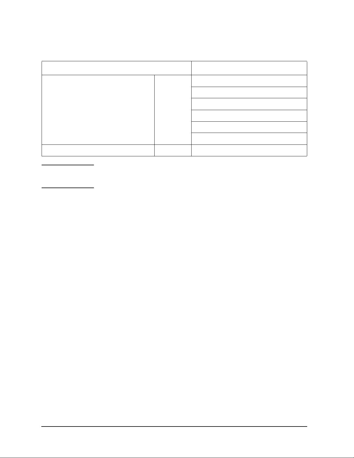
Measurement Capability on Thermal Test
The B1505A measurement capabilities supported on the thermal test are summarized in
T able 1-16. Qg tests are not supported on the thermal test.
Table 1-16 Measurement Capability and Requirements
Configuration Guide
Capability Fixture
• IV test up to 20 A, 3 kV N1259A Yes
• IV test up to 1500 A, 3 kV N1265A Yes
• IV test up to 1500 A, 10 kV
•CV test
• Qg test up to 20 A, 3 kV N1259A No No
• Qg test up to 1100 A, 3 kV N1265A No No
N1265A Yes
Thermal Plate
Solution
(with N1271A-001)
(with N1271A-001)
(with N1271A-001)
Thermostream
Solution
No
Yes
(with N1271A-002)
Yes
(with N1271A-005)
Information of inTEST Thermal Plate and Thermostream
The B1505A with the N1271A supports the Thermal Plate and the Thermostream of
inTEST corporation. Supported models are listed below but contact inTEST for more
information, sales@inTESTthermal.com.
Keysight B1505A Configuration and Connection Guide 1-39
Page 48

Configuration Guide
Pre-configured Power Device Analyzer/Curve Tracer (B1505A with Modules/Fixture)
Pre-configured Power Device Analyzer/Curve Tracer (B1505A with Modules/Fixture)
The Keysight B1505AP Pre-configured packages include all necessary modules, cables
and accessories.
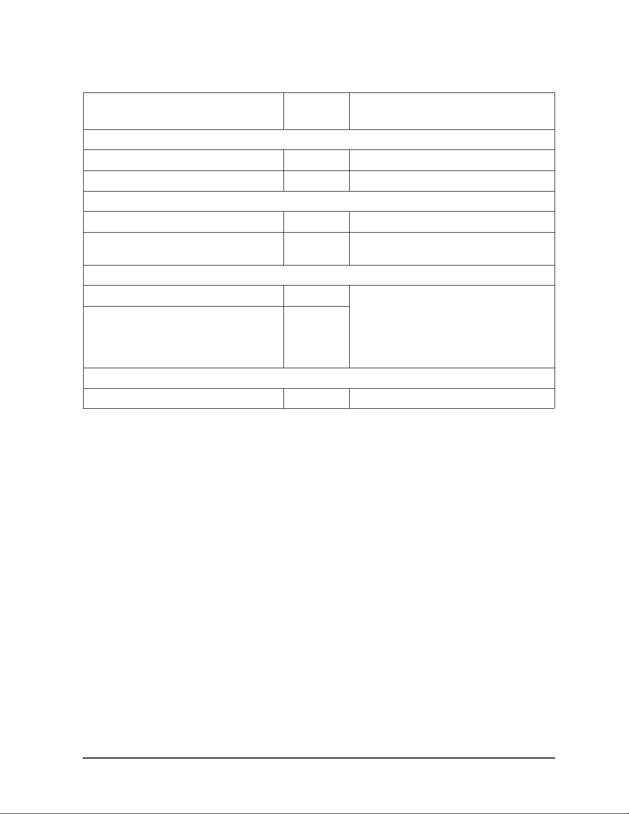
Table 1-17 B1505AP Pre-configured package
Product Number Description
B1505AP Pre-configured Power Device Analyzer/Curve Tracer (B1505A w/
modules/fixture)
Option Max V Max I C-V Note
H20 3 kV 20 A 3 kV / 20 A / Fixture Pack
H21 3 kV 20 A Yes 3 kV / 20 A / C-V / Fixture Pack
H50 3 kV 500 A 3 kV / 500 A / Fixture Pack
H51 3 kV 500 A Yes 3 kV / 500 A / C-V / Fixture Pack
H70 3 kV 1500 A 3 kV / 1500 A / Fixture Pack
H71 3 kV 1500 A Yes 3 kV / 1500 A / C-V / Fixture Pack
U50 10 kV 500 A 1 0 kV / 500 A / Fixture Pack
U70 10 kV 1500 A 10 kV / 1500 A / Fixture Pack
Table 1-18 B1505AP-H20 3 kV / 20 A / Fixture Package
Description Qty Note
B1505A 1 Power Device Analyzer / Curve Tracer Mainframe
• Include 16493J-001 Interlock cable (1.5 m), 16493L-001 GNDU cable (1.5
m), 16444A-001 Keyboard, 16444A-002 Mouse, 16444A-003 Stylus pen.
B1512A-FG 1 High Current Source Monitor Unit Module
• Include 16493S-001 HCSMU cable (1.5 m) 1ea and 16493S-010 Kelvin
adapter.
B1513C-FG 1 High Voltage Source Monitor Unit
• Include 16493T-001 HVSMU cable (1.5 m).
B1514A-FG 1 Medium Current Source Monitor Unit
• Include 16494A-001 Triaxial cable (1.5 m) 2ea.
N1259A 1 Test Fixture for Power Device
1-40 Keysight B1505A Configuration and Connection Guide
Page 49

Pre-configured Power Device Analyzer/Curve Tracer (B1505A with Modules/Fixture)
Description Qty Note
N1259A-001 1 Test Fixture including Inline Package Socket Module and Cables
• Include N1259A-010 Inline package socket module (3 pin), N1254A-508
Banana to banana cable black 4ea and N1254A-509 Banana to banana
cable red 6ea.
N1259A-300 1 Module Selector
• Include 16493G-001 Digital I/O control cable.
N1259A-022 1 100 kohm R-box
N1259A-030 1 1 kohm R-box for gate
N1254A 1 Accessories for instruments and fixtures
N1254A-104 1 Triax (f) to BNC (m) adaptor
Table 1-19 B1505AP-H21 3 kV / 20 A / C-V / Fixture Package
Description Qty Note
Configuration Guide
B1505A 1 Power Device Analyzer / Curve Tracer Mainframe
• Include 16493J-001 Interlock cable (1.5 m), 16493L-001 GNDU cable (1.5
m), 16444A-001 Keyboard, 16444A-002 Mouse, 16444A-003 Stylus pen.
B1512A-FG 1 High Current Source Monitor Unit Module
• Include 16493S-001 HCSMU cable (1.5 m) 1ea and 16493S-010 Kelvin
adapter.
B1513C-FG 1 High Voltage Source Monitor Unit
• Include 16493T-001 HVSMU cable (1.5 m).
B1514A-FG 1 Medium Current Source Monitor Unit
• Include 16494A-001 Triaxial cable (1.5 m) 2ea.
B1520A-FG 1 Multi Frequency Capacitance Measurement Unit Module
• Include N1300A-001 CMU cable (1.5 m)
N1259A 1 Test Fixture for Power Device
N1259A-001 1 Test Fixture including Inline Package Socket Module and Cables
• Include N1259A-010 Inline package socket module (3 pin), N1254A-508
Banana to banana cable black 4ea and N1254A-509 Banana to banana
cable red 6ea.
N1259A-300 1 M odule Selector
• Include 16493G-001 Digital I/O control cable.
N1259A-020 1 High Voltage Bias-Tee
• Include N1254A-512 SHV Cable 250 mm, 2ea and N1254A-513 SHV Jack
to Banana Adapter, 2ea.
N1259A-022 1 100 kohm R-box
Keysight B1505A Configuration and Connection Guide 1-41
Page 50

Configuration Guide
Pre-configured Power Device Analyzer/Curve Tracer (B1505A with Modules/Fixture)
Description Qty Note
N1259A-030 1 1 kohm R-box for gate
N1254A 1 Accessories for instruments and fixtures
N1254A-104 1 Triax (f) to BNC (m) adaptor
Table 1-20 B1505AP-H50 3 kV / 500 A / Fixture Package
Description Qty Note
B1505A 1 Power Device Analyzer / Curve Tracer Mainframe
• Include 16493J-001 Interlock cable (1.5 m), 16493L-001 GNDU cable (1.5
m), 16444A-001 Keyboard, 16444A-002 Mouse, 16444A-003 Stylus pen.
B1513C-FG 1 High Voltage Source Monitor Unit
• Include 16493T-001 HVSMU cable (1.5 m).
B1514A-FG 3 Medium Current Source Monitor Unit
• Include 16494A-001 Triaxial cable (1.5 m) 2ea.
N1265A 1 Ultra High Current Expander / Fixture
N1265A-001 1 Ultra High Current Expander / Fixture
• Include 16493G-001Control cable (1.5 m) and a Blanck silicon plate.
N1265A-010 1 500 A Ultra High Current 3-pin Inline Package Socket Module
• Include N1254A-522 1500 A Ultra High Current Banana to Banana Cable
(yellow, 2ea), N1254A-508 Banana to Banana Cable, 250 mm (red, 1ea),
N1254A-509 Banana to Banana Cable, 250 mm (black, 1ea), N1265-61751
T est Lead 180mm (red, 1ea) and N1265A-61752 Test Lead 180mm (black,
1ea).
N1254A 1 Accessories for instruments and fixtures
N1254A-508 4 Banana to Banana Cable 250 mm (red, 1ea)
N1254A-509 4 Banana to Banana Cable 250 mm (black, 1ea)
N1254A-510 3 Dolphin Clip 2 ea. (red and black)
Table 1-21 B1505AP-H51 3 kV / 500 A / C-V / Fixture Package
Description Qty Note
B1505A 1 Power Device Analyzer / Curve Tracer Mainframe
• Include 16493J-001 Interlock cable (1.5 m), 16493L-001 GNDU cable (1.5
m), 16444A-001 Keyboard, 16444A-002 Mouse, 16444A-003 Stylus pen.
B1513C-FG 1 High Voltage Source Monitor Unit
• Include 16493T-001 HVSMU cable (1.5 m).
B1514A-FG 3 Medium Current Source Monitor Unit
• Include 16494A-001 Triaxial cable (1.5 m) 2ea.
1-42 Keysight B1505A Configuration and Connection Guide
Page 51

Pre-configured Power Device Analyzer/Curve Tracer (B1505A with Modules/Fixture)
Description Qty Note
B1520A-FG 1 Multi Frequency Capacitance Measurement Unit Module
• Include N1300A-001 CMU cable (1.5 m)
N1260A 1 High Voltage Bias-Tee
N1260A-STD 1 High Voltage Bias-Tee
N1265A 1 Ultra High Current Expander / Fixture
N1265A-001 1 Ultra High Current Expander / Fixture
• Include 16493G-001Control cable (1.5 m) and a Blanck silicon plate.
N1265A-010 1 500 A Ultra High Current 3-pin Inline Package Socket Module
• Include N1254A-522 1500 A Ultra High Current Banana to Banana Cable
(yellow, 2ea), N1254A-508 Banana to Banana Cable, 250 mm (red, 1ea),
N1254A-509 Banana to Banana Cable, 250 mm (black, 1ea), N1265-61751
T est Lead 180mm (red, 1ea) and N1265A-61752 Test Lead 180mm (black,
1ea).
N1254A 1 Accessories for instruments and fixtures
Configuration Guide
N1254A-508 4 Banana to Banana Cable 250 mm (red, 1ea)
N1254A-509 4 Banana to Banana Cable 250 mm (black, 1ea)
N1254A-510 3 Dolphin Clip 2 ea. (red and black)
N1254A-512 2 SHV Cable 250 mm
N1254A-513 2 S HV Jack to Banana Adapter
N1254A-518 2 SHV Cable 1.5 m
Table 1-22 B1505AP-H70 3 kV / 1500 A / Fixture Package
Description Qty Note
B1505A 1 Power Device Analyzer / Curve Tracer Mainframe
• Include 16493J-001 Interlock cable (1.5 m), 16493L-001 GNDU cable (1.5
m), 16444A-001 Keyboard, 16444A-002 Mouse, 16444A-003 Stylus pen.
B1513C-FG 1 High Voltage Source Monitor Unit
• Include 16493T-001 HVSMU cable (1.5 m).
B1514A-FG 3 Medium Current Source Monitor Unit
• Include 16494A-001 Triaxial cable (1.5 m) 2ea.
N1265A 1 Ultra High Current Expander / Fixture
N1265A-001 1 Ultra High Current Expander / Fixture
• Include 16493G-001Control cable (1.5 m) and a Blanck silicon plate.
Keysight B1505A Configuration and Connection Guide 1-43
Page 52

Configuration Guide
Pre-configured Power Device Analyzer/Curve Tracer (B1505A with Modules/Fixture)
Description Qty Note
N1265A-010 1 500 A Ultra High Current 3-pin Inline Package Socket Module
• Include N1254A-522 1500 A Ultra High Current Banana to Banana Cable
(yellow, 2ea), N1254A-508 Banana to Banana Cable, 250 mm (red, 1ea),
N1254A-509 Banana to Banana Cable, 250 mm (black, 1ea), N1265-61751
T est Lead 180mm (red, 1ea) and N1265A-61752 Test Lead 180mm (black,
1ea).
N1265A-015 1 1500 A Current Option
N1254A 1 Accessories for instruments and fixtures
N1254A-508 4 Banana to Banana Cable 250 mm (red, 1ea)
N1254A-509 4 Banana to Banana Cable 250 mm (black, 1ea)
N1254A-510 3 Dolphin Clip 2 ea. (red and black)
N1254A-522 1 15 00 A Ultra High Current Banana to Banana Cable, 2 ea.
Table 1-23 B1505AP-H71 3 kV / 1500 A / C-V / Fixture Package
Description Qty Note
B1505A 1 Power Device Analyzer / Curve Tracer Mainframe
• Include 16493J-001 Interlock cable (1.5 m), 16493L-001 GNDU cable (1.5
m), 16444A-001 Keyboard, 16444A-002 Mouse, 16444A-003 Stylus pen.
B1513C-FG 1 High Voltage Source Monitor Unit
• Include 16493T-001 HVSMU cable (1.5 m).
B1514A-FG 3 Medium Current Source Monitor Unit
• Include 16494A-001 Triaxial cable (1.5 m) 2ea.
B1520A-FG 1 Multi Frequency Capacitance Measurement Unit Module
• Include N1300A-001 CMU cable (1.5 m)
N1260A 1 High Voltage Bias-Tee
N1260A-STD 1 High Voltage Bias-Tee
N1265A 1 Ultra High Current Expander / Fixture
N1265A-001 1 Ultra High Current Expander / Fixture
• Include a 16493G-001Control cable (1.5 m) and a Blanck silicon plate.
N1265A-010 1 500 A Ultra High Current 3-pin Inline Package Socket Module
• Include N1254A-522 1500 A Ultra High Current Banana to Banana Cable
(yellow, 2ea), N1254A-508 Banana to Banana Cable, 250 mm (red, 1ea),
N1254A-509 Banana to Banana Cable, 250 mm (black, 1ea), N1265-61751
T est Lead 180mm (red, 1ea) and N1265A-61752 Test Lead 180mm (black,
1ea).
N1265A-015 1 1500 A Current Option
N1254A 1 Accessories for instruments and fixtures
1-44 Keysight B1505A Configuration and Connection Guide
Page 53

Pre-configured Power Device Analyzer/Curve Tracer (B1505A with Modules/Fixture)
Description Qty Note
N1254A-508 4 Banana to Banana Cable 250 mm (red, 1ea)
N1254A-509 4 Banana to Banana Cable 250 mm (black, 1ea)
N1254A-510 3 Dolphin Clip 2 ea. (red and black)
N1254A-512 2 SHV Cable 250 mm
N1254A-513 2 S HV Jack to Banana Adapter
N1254A-518 2 SHV Cable 1.5 m
N1254A-522 1 15 00 A Ultra High Current Banana to Banana Cable, 2 ea.
Table 1-24 B1505AP-U50 10 kV / 500 A / Fixture Package
Description Qty Note
B1505A 1 Power Device Analyzer / Curve Tracer Mainframe
• Include 16493J-001 Interlock cable (1.5 m), 16493L-001 GNDU cable (1.5
m), 16444A-001 Keyboard, 16444A-002 Mouse, 16444A-003 Stylus pen.
Configuration Guide
B1514A-FG 5 Medium Current Source Monitor Unit
• Include 16494A-001 Triaxial cable (1.5 m) 2ea.
N1265A 1 Ultra High Current Expander / Fixture
N1265A-001 1 Ultra High Current Expander / Fixture
• Include 16493G-001 Control cable (1.5 m) and a Blanck silicon plate.
N1265A-010 1 500 A Ultra High Current 3-pin Inline Package Socket Module
• Include N1254A-522 1500 A Ultra High Current Banana to Banana Cable
(yellow, 2ea), N1254A-508 Banana to Banana Cable, 250 mm (red, 1ea),
N1254A-509 Banana to Banana Cable, 250 mm (black, 1ea), N1265-61751
T est Lead 180mm (red, 1ea) and N1265A-61752 Test Lead 180mm (black,
1ea).
N1265A-040 1 10 kV Ultra High Voltage Gate Protection Adapter
N1268A 1 Ultra High Voltage Expander
N1268A-STD 1 Ultra High Voltage Expander
• Include 16493G-001 Control cable (1.5 m), 16493J-001 Interlock cable
(1.5m).
16493V-001 1 10 kV Ultra High Voltage Cable, 1.5 m
• Include one UHV cable (red) and one SHV cable (black).
N1254A 1 Accessories for instruments and fixtures
N1254A-508 4 Banana to Banana Cable 250 mm (red, 1ea)
N1254A-509 4 Banana to Banana Cable 250 mm (black, 1ea)
Keysight B1505A Configuration and Connection Guide 1-45
Page 54

Configuration Guide
Pre-configured Power Device Analyzer/Curve Tracer (B1505A with Modules/Fixture)
Description Qty Note
N1254A-510 3 Dolphin Clip 2 ea. (red and black)
N1254A-520 1 10 kV Ultra High Voltage Open End Cable, 1m (pair)
N1254A-522 1 15 00 A Ultra High Current Banana to Banana Cable, 2 ea
Table 1-25 B1505AP-U70 10 kV / 500 A / Fixture Package
Description Qty Note
B1505A 1 Power Device Analyzer / Curve Tracer Mainframe
• Include 16493J-001 Interlock cable (1.5 m), 16493L-001 GNDU cable (1.5
m), 16444A-001 Keyboard, 16444A-002 Mouse, 16444A-003 Stylus pen.
B1514A-FG 5 Medium Current Source Monitor Unit
• Include 16494A-001 Triaxial cable (1.5 m) 2ea.
N1265A 1 Ultra High Current Expander / Fixture
N1265A-001 1 Ultra High Current Expander / Fixture
• Include 16493G-001 Control cable (1.5 m) and a Blanck silicon plate.
N1265A-010 1 500 A Ultra High Current 3-pin Inline Package Socket Module
• Include N1254A-522 1500 A Ultra High Current Banana to Banana Cable
(yellow, 2ea), N1254A-508 Banana to Banana Cable, 250 mm (red, 1ea),
N1254A-509 Banana to Banana Cable, 250 mm (black, 1ea), N1265-61751
T est Lead 180mm (red, 1ea) and N1265A-61752 Test Lead 180mm (black,
1ea).
N1265A-015 1 1500 A Current Option
N1265A-040 1 10 kV Ultra High Voltage Gate Protection Adapter
N1268A 1 Ultra High Voltage Expander
N1268A-STD 1 Ultra High Voltage Expander
• Include 16493G-001 Control cable (1.5 m), 16493J-001 Interlock cable
(1.5m).
16493V-001 1 10 kV Ultra High Voltage Cable, 1.5 m
• Include one UHV cable (red) and one SHV cable (black).
N1254A 1 Accessories for instruments and fixtures
N1254A-508 4 Banana to Banana Cable 250 mm (red, 1ea)
N1254A-509 4 Banana to Banana Cable 250 mm (black, 1ea)
N1254A-510 3 Dolphin Clip 2 ea. (red and black)
N1254A-520 1 10 kV Ultra High Voltage Open End Cable, 1m (pair)
N1254A-522 1 15 00 A Ultra High Current Banana to Banana Cable, 2 ea
1-46 Keysight B1505A Configuration and Connection Guide
Page 55

Configuration Guide
Pre-configured Power Device Analyzer/Curve Tracer (B1505A with Modules/Fixture)
NOTE Cable length is 1.5 m only (No cable length option).
NOTE To add additional modules such as a B1511B MPSMU into the B1505AP package, the
B1505AU with corresponding module option has to be ordered and users have to send their
B1505A mainframe to Keysight Service Center for installing modules. So, building a
B1505A configuration from scratch is recommended.
NOTE To add additional accessories of the N1259A or N1265A, please order them separately
using the N1259AU or N1265AU with corresponding options.
Keysight B1505A Configuration and Connection Guide 1-47
Page 56

Configuration Guide
Condition Gate Drain Source
Other bias
500 A
N1265A UHC Expander / Fixture
+ N1254A-524 Ultra High Current Prober
System Cable
MCSMU*<=30A with Module
Selector
MCSMU* +
R-box
N1258A Module Selector
<=40A without Module
Selector
Direct Direct
Condition Gate Drain Source
Other bias
10 kV** N1269A UHV direct N1269A
MCSMU +
N1269A
* We recommend B1514A MCSMU for a Gate SMU and other bias SMUs.
** We should manually change cabling for a 10 kV measurement
Accessories for Wafer Prober and Your Own Test Fixture
Accessories for Wafer Prober and Your Own Test
Fixture
T able 1-26 lists the accessories available for wafer probers or your own test fixtures. Select
the required accessories.
Figure 1-4 Connection to probers
Figure 1-5 Connection between the N1265A Ultra High Current Expander / Fixture and Prober
with the N1254A-524 Ultra High Current Prober System
1-48 Keysight B1505A Configuration and Connection Guide
Page 57

Configuration Guide
Accessories for Wafer Prober and Your Own Test Fixture
Table 1-26 Accessories for Wafer Prober or Your Own Fixture
Model/Option Description Additional Information
Module Selector
N1258A Module Selector for B1505A • The N1258A is furnished with 1.5 m
digital I/O control cable (16493G-001).
Maximum 65 VA
• The N1258A has a built-in GNDU
protection adapter, a built-in HPSMU
protection adapter and a built-in
HCSMU Kelvin adapter.
• Do not connect or put any conductor on
the HCSMU Low Force and Low Sense
terminals, outer conductor of the
coaxial connectors. Connecting or
putting conductor of circuit common,
chassis ground, or any potential on
causes the measurement error.
For High Voltage Capacitance Measurement
N1260A High Voltage Bias-Tee • The N1260A-STD is a mandatory
option.
• The N1260A High Voltage Bias-Tee is
not furnished with any cables.
Keysight B1505A Configuration and Connection Guide 1-49
Page 58

Configuration Guide
Accessories for Wafer Prober and Your Own Test Fixture
Model/Option Description Additional Information
Protection Adapter
N1261A-001 Protection adapter for High Power Source
Monitor Unit (Triaxial output)
N1261A-002 Protection Adapter Ground Unit (BNC
output)
N1261A-003 Protection adapter for High Power Source
Monitor Unit (HV-Triaxial output)
N1261A-004 Protection Adapter Ground Unit (SHV
output)
• Two Triaxial inputs (Force/Sense) and
two Triaxial outputs (Force/Sense).
• This adapter is used to protect not only
B1510A HPSMU but also B1511A/B
MPSMU.
• One Triaxial input for GNDU and two
BNC outputs (Force/Sense).
• Two Triaxial inputs (Force/Sense) and
two High Voltage Triaxial outputs.
• This adapter is used to protect not only
B1510A HPSMU but also B1511A/B
MPSMU.
• One Triaxial input for GNDU and two
SHV outputs (Force/Sense).
High Voltage R-box
N1262A-001 1Mohm R-box • One High Voltage Triaxial input and
one SHV output.
N1262A-002 100 kohm R-box • One High Voltage Triaxial input and
one SHV output.
1-50 Keysight B1505A Configuration and Connection Guide
Page 59

Configuration Guide
Accessories for Wafer Prober and Your Own Test Fixture
Model/Optio
N1262A-010 1 kohm R-box for gate (Triaxial output) • One Triaxial input and one Triaxi
N1262A-011 1 kohm R-box for gate (SHV output) • One High Voltage Triaxial input an
N1262A-020 Universal R-Box, Triaxial • One Triaxial input and one Triaxi
N1262A-021 Universal R-Box, HV Triaxial to SHV • One High Voltage Triaxial input an
n Descri
ption Additional Information
outp
ut.
V output.
one SH
outp
ut.
V output.
one SH
al
d
al
d
N1262A-036 50 Ohm Termination Adapter • The N1262A-036 is used to avoi
device oscil
gate cabli
lation by inserting it to th
ng.
d
e
Keysight B1505A Configuration and Connection Guide 1-51
Page 60

Configuration Guide
16493S
Opt 010
HCSMU Kelvin Adapter
ForceSense
From HCSMU
Output
Signal
Circuit
Common
High Sense
High Force
Low Sense
Low Force
Ag ilen t
㼼40 V m ax
䞉䞉䞉
16493S
Opt 010
HCSMU Kelvin Adapter
ForceSense
From HCSMU
Output
Signal
Circuit
Common
Signal
Circuit
Common
High Sense
High Force
Low Sense
Low Force
Ag ilen t
㼼40 V m ax
䞉䞉䞉
㼼40 V m ax
䞉䞉䞉䞉䞉䞉
16493S
Opt 011
HCSMU Non-Kelvin Adapter
ForceSense
From HCSMU
Output
Signal
Circuit
Common
High Force
Low Force
Ag ilen t
㼼40 V max
䞉䞉䞉
16493S
Opt 011
HCSMU Non-Kelvin Adapter
ForceSense
From HCSMU
Output
Signal
Circuit
Common
Signal
Circuit
Common
High Force
Low Force
Ag ilen t
㼼40 V max
䞉䞉䞉
㼼40 V max
䞉䞉䞉䞉䞉䞉
Accessories for Wafer Prober and Your Own Test Fixture
Model/Option Description Additional Information
HCSMU Adapter
16493S-010 High Current Source Monitor Unit Kelvin
Adapter
16493S-011 High Current Source Monitor Unit
non-Kelvin Adapter
• One Triaxial input and one BNC input
for HCSMU and four BNC outputs
(High Force/Sense, Low Force/Sense)
• Do not connect or put any conductor on
the HCSMU Low Force and Low Sense
terminals, outer conductor of the
coaxial connectors.
• Connecting or putting conductor of
circuit common, chassis ground, or any
potential on causes the measurement
error.
• One Triaxial input and one BNC input
for HCSMU and two BNC outputs
(High Force/Low Force).
• Do not connect or put any conductor on
the HCSMU Low Force and Low Sense
terminals, outer conductor of the
coaxial connectors.
• Connecting or putting conductor of
circuit common, chassis ground, or any
potential on causes the measurement
error.
1-52 Keysight B1505A Configuration and Connection Guide
Page 61

Configuration Guide
Accessories for Wafer Prober and Your Own Test Fixture
Model/Option Description Additional Information
Dual HCSMU Adapter
16493S-020 Adapter, 40A, when connecting to wafer
prober directly without N1258A selector
• Output connectors are compatible with
N1258A module selector.
• This adapter has a built-in GNDU
protection adapter and a built-in
HCSMU Kelvin adapter.
• This adapter cannot be used with
N1258A module selector and N1259A
test fixture.
• Do not connect or put any conductor on
the HCSMU Low Force and Low Sense
terminals, outer conductor of the
coaxial connectors.
• Connecting or putting conductor of
circuit common, chassis ground, or any
potential on causes the measurement
error.
Keysight B1505A Configuration and Connection Guide 1-53
Page 62

Configuration Guide
Accessories for Wafer Prober and Your Own Test Fixture
Model/Option Description Additional Information
16493S-021 Adapter, 40A, select this if 16493S-020 is
not used
• This adapter is used with the N1259A
T est Fixture, N1258A Module Selector,
or 16493S-010/011 HCSMU Adapter
• If a N1258A Module Selector is used
with this adapter, the maximum current
is limited to 30 A. If 40 A capability is
needed, please connect this adapter to
device directly.
• Output connectors are compatible with
B1512A HCSMU.
• The 16493S-021 is furnished with one
30cm Triaxial cable and one 30 cm
High current coaxial cable for output
connection.
• Do not connect or put any conductor on
the HCSMU Low Force and Low Sense
terminals, outer conductor of the
coaxial connectors.
• Connecting or putting conductor of
circuit common, chassis ground, or any
potential on causes the measurement
error.
For Ultra High Current Measurement
N1254A-524 Ultra High Current Prober System Cable • The N1254A-524 cable is furnished
with one transparent shield with a slit.
• Maximum current range is about 800 A
or more.
• Cable length is 1.8 m.
1-54 Keysight B1505A Configuration and Connection Guide
Page 63

Configuration Guide
Accessories for Wafer Prober and Your Own Test Fixture
Model/Option Description Additional Information
For Ultra High Voltage Measurement
N1269A Ultra High V oltage Connection Adapter • The N1269A adapter is used to protect
measurement resources from
unexpected surge when connecting the
N1268A Ultra High Voltage Expander
to a wafer prober.
• Protection adapter for the B1514A
MCSMU is included in the N1269A
adapter.
• This adapter supports the B1514A
MCSMU only.
N1254A-521 10 kV Ultra High Voltage Jack to Jack
Adapter
N1262A-023 Universal R-Box for Ultra High Voltage • Two Ultra High Vo ltage ports.
• Feed through adapter set of UHV and
SHV connectors
Keysight B1505A Configuration and Connection Guide 1-55
Page 64

Configuration Guide
!
Accessories for Wafer Prober and Your Own Test Fixture
Model/Option Description Additional Information
For Gate Charge Measurement
N1274A On-Wafer Gate Charge Measurement
Adapter/Selector for 20 A/3 kV
N1275A On-Wafer Gate Charge Measurement
Adapter for N1265AUltra High Voltage
Connection Adapter
• The N1274A is an adapter to enable
on-wafer gate charge measurements
using the HCSMU (max. 20 A) and
HVSMU (max. 3 kV).
• This equips an internal selector to
automatically switch signal paths of I-V
measurement and gate charge
measurement.
• The selector relays in the N1274A are
controlled by the N1258A module
selector.
• You can also mount a current control
device or load resistor on the N1274 by
opening a small panel on the top of this
adapter.
• The N1275A is an adapter to enable
on-wafer gate charge measurements
with the UHCU (max. 500 A) and
HVSMU (max. 3 kV).
• The adapter output can be extended to
your prober station by using the
N1254A-524 prober system cable.
• You can also mount current control
device or load resistor for the gate
charge measurement on the top of this
adapter.
1-56 Keysight B1505A Configuration and Connection Guide
Page 65

Configuration Guide
Other Accessories
Other Accessories
The following table lists the options and accessories available for the B1505A.
Table 1-27 Options and Accessories
Model/Option Description Additional Information
Keysight EasyEXPERT software
B1540A-001 Standard edition
Keysight Desktop EasyEXPERT software
B1541A-001 Standard edition
Accessories for B1500 series
16444A-001 USB keyboard
16444A-002 USB m ouse
16444A-003 Stylus pen
Cables, adapters, interlock
16493K-001 Kelvi n Triaxial Cable, 1.5 m length • Cable length 1.5 m or 3.0 m can
16493K-002 Kelvin Triaxial Cable. 3.0 m length
be specified by option 001 or
002.
• These cables are NOT
supported by the N1265A,
N1266A, N1267A and
N1268A.
Keysight B1505A Configuration and Connection Guide 1-57
Page 66

Configuration Guide
Other Accessories
Model/Option Description Additional Information
16493U-001 High current coaxial cable, BNC(m) to BNC(m), 1.5 m• Cable length 1.5 m or 3.0 m can
be specified by option 001 or
16493U-002 High current coaxial cable, BNC(m) to BNC(m), 3 m
8120-1838 BNC cable, 30 cm (12 inch)
8120-1839 BNC cable, 60 cm (24 inch)
N1254A-500 HV jack connect or, panel mount, for soldering, 1 ea.
N1254A-501 HV jack to HV jack adapter, panel mount, 1 ea.
002.
N1254A-502 HV plug connector, panel mount, for soldering, 1 ea.
N1254A-503 HCSMU Coaxial Cable Assy 1.5 m - BNC to
Open-End, 1 ea.
N1254A-505 HVSMU Triaxial Cable Assy 1.5 m - HV Plug to
Open-End, 1 ea.
N1254A-506 HVSMU Coaxial Cable Assy 1.5 m - HV Plug to
Open-End, 1 ea.
N1254A-507 HVSMU Coaxial Cable Assy 1.5 m, 1 ea.
N1254A-514 BNC(m) to BNC(m) adapter, 1 ea.
N1254A-515 BNC(f)-BNC(m)-BNC(f) adapter, 1 ea.
1-58 Keysight B1505A Configuration and Connection Guide
Page 67

Configuration Guide
Other Accessories
Model/Option Description Additional Information
N1254A-516 BNC(f)-BNC(f)-BNC(f) adapter, 1 ea.
N1254A-517 Triax(f)-Triax(m) adapter, shield separated, 1 ea.
N1254A-518 SHV(plug)-SHV(plug) coax ial cable, 1.5 m, 1 ea.
N1254A-520 UHV(plug) to no connector cable, 1 m, 1 ea. and
SHV(plug) to no connector cable, 1 m, 1 ea.
N1254A-521 UHV(jack)-UHV(jack) adapter, 1 ea. and
SHV(jack)-SHV(jack) adapter, 1 ea.
N1254A-522 Connection wire, banana-to-banana, maximum 1500
A, 2 ea.
N1254A-523 Banana to no connector wire, maxim um 1500 A, 1
m, 2 ea.
N1254A-524 System cable for prober, 1.8 m, 1 ea.
N1254A-525 SHV Cable Assy 1.5m - SHV Plug To Open-end, 1
ea.
N1254A-526 Ultra High Current Cable, 2m , No Connectors At
Either End, 1 ea.
N1254A-527 PTFE Standoff, Jack, 4 ea.
N1254A-528 PTFE Standoff With Banana Plug, 4 ea.
N1254A-554 Thermocouple, Type K, 75 cm, 2 ea.
N1254A-556 Test Leads and Connection Kit for Capacitance Test,
four 20 cm alligator clip - lug cables, four banana
plugs, four nuts, and four spare clips
Keysight B1505A Configuration and Connection Guide 1-59
Page 68

Configuration Guide
Other Accessories
Model/Option Descriptio
1250-2405 BNC-T Plug(m)-BNC(f)-BNC(f) adapter, 1ea
1251-2277 Banana to BNC adapter
1252-1419 Interlock receptacle connector
n Ad
ditional Information
1-60 Keysight B1505A Configuration and Connection Guide
Page 69

Retrofit Products for B1505A
The Keysight B1505A has 10 slots so that users can install appropriate modules into
B1505A mainframe. The retrofit module product is available to add more modules into
existing B1505A mainframe. These modules have to be installed in Keysight Technologies
service center to meet the specifications.
The following table lists the module products and the available accessories.
Table 1-28 Module pr oducts and available accessories
Configuration Guide
Retrofit Products for B1505A
Model/
Optio
n
B1505AU Upgrade kit for B1505A
Software license to use advanced functions
B1505AU-SWS EasyEXPERT Extension support and subscription • B1505A users who have not
B1505A mainframe upgrade
B1500AU-PC2 Mainframe upgrade (available for S/N starts with
JP or less than MY53440000)
B1500AU-PC3 Mainframe upgrade (available for S/N
MY53440101 or later)
Measurement module
Descriptio
n Note
purchased a B150
have to update EasyEXPERT
software to version 5.5 or
later.
• The B1505AU-SWS includes
15 licenses which can
used for both EasyEXPERT
and Desktop EasyEXPERT.
Including OS (from Windows
XP/7
to Windows 10), CPU,
mother board, storage (from
to SSD), VGA output.
HDD
Contact Keysight Technologies
upgrade the B1500A.
to
5A-SWS
be
B15
05AU-010 High Power Source/Monitor Unit Module (B1510A) Modules are NOT furnished with
B1505AU-011 Medium Power Source/Monitor Unit Module
(B1511B)
B1505AU-012 High Current Source Monitor Unit Module (B1512A)
B1505AU-013 High Voltage Source Monitor Unit (B1513C)
B1505AU-014 Medium Current Source Monitor Unit (B1514A)
B1505AU-020 Multi Frequency Capacitance Measurement Unit
Module (B1520A)
Keysight B1505A Configuration and Connection Guide 1-61
any cables. Order the required
cables and accessories separately.
Page 70

Configuration Guide
Retrofit Products for B1505A
Model/
Opti
on
Description No
B1510A HPSMU, B1511A/B MPSMU and B1514A MCSMU cables
16494A-001 1.5m length triaxial cable
16494A-002 3 m length triaxial cable
16494A-003 80 cm length triaxial cable
16494A-004 40 cm length triaxial cable
4
16494A-005
m length triaxial cable
16493K-001 1.5 m length Kelvin triaxial cable
16493K-002 3 m length Kelvin triaxial cable
B1512A HCSMU cables and adapters
16493S-001 1.5 m length
16493S-002 3 m length
16493S-010
16493S-011
16493S-020
1
1
1
HCSMU Kelvin adapter
HCSMU non-Kelvin adapter
Dual HCSMU combination adapter, for 40 A
measurement, when connecting to wafer prober
directly without N1258A selector
te
16493S-021
1
Dual HCSMU combination adapter, for 40 A
measurement, when being used with N1259A test
fixture, N1258A module selector, or 16493S-010/011
HCSMU adapter
The 16493S-021 is furnished
with one 30cm Triaxial cable and
one 30 cm High current coaxial
cable for output connection.
B1513A/B/C HVSMU cables
16493T-001 1.5 m length
16493T-002 3 m length
B1520A CMU cables
N1300A-001 1.5 m length
N1300A-002 3 m length
1. Do not connect or put any conductor on the HCSMU Low Force and Low Sense terminals, outer conductor of the coaxial connectors. Connecting or putting conductor of circuit common, chassis ground
any potential on causes the measurement error.
or
,
NOTE For customers, module upgrades to existing B1505A systems must be carried out at an
Keysight Technologies service center. In order to ensure system specifications the new
modules need to be installed and the complete unit calibrated. Contact your nearest
Keysight Technologies office to arrange the installation and calibration of new B1505A
modules.
1-62 Keysight B1505A Configuration and Connection Guide
Page 71

Configuration Guide
Retrofit Products for B1505A
NOTE For Keysight field team, installation fee (R-51U-501 or R1286A-HU) will be
automatically added to the B1505AU when making a quotation with Keysight order
configuration tool.
NOTE E5288A ASU (Atto Sense and Switch Unit) is not supported by the B1505A.
NOTE Under the total power consumption limit, there is configuration limitation. Please refer to
Table 1-4 on page 1-7.
Keysight B1505A Configuration and Connection Guide 1-63
Page 72

Configuration Guide
Conversion Kit from B1500A to B1505A
Conversion Kit from B1500A to B1505A
The following table lists the requirements and the available accessories for remodelling the
B1500A to the B1505A.
Table 1-29 Required and Available Accessories for Remodelling B1500A to B1505A
Model/
Option
B1
505AU-001 Conversion kit from B1500A to
B1505A
NOTE For customers, Keysight Technologies service center is responsible for remodelling and
module installation. Contact Keysight Technologies to get a quotation.
NOTE For Keysight field team, installation fee (R-51U-501 or R1286A-HU) will be
automatically added to the B1505AU when making a quotation with Keysight order
configuration tool.
NOTE The instrument firmware and software will be updated to the latest version at the service
center. So make a back up of data saved in the built-in SSD by yourself before sending the
instrument to the service center.
NOTE The 16442A/16442B test fixture supports up to 200 V / 1A. So use the N1259A or the
N1265A, which are designed for supporting the B1505A. See "N1259A Test Fixture for
Power Device" or "N1265A Ultra High Current Expander/Fixture".
Description Note
The B1505AU-001 is NOT furnished with any
cables. It doesn’t include any modules. Select
modules or accessories separately. Please refer to
"Retrofit Products for B1505A" on page 1-61.
NOTE B1517A HRSMU (high resolution SMU), E5288A ASU (Atto Sense and Switch Unit),
B1530A WGFMU (Waveform Generator / Fast Measurement Unit), and B1525A SPGU
(High Voltage Semiconduct or Pulse Generator Unit) are not sup ported by the B1505A.
1-64 Keysight B1505A Configuration and Connection Guide
Page 73

Upgrade Kit for N1259AU Test Fixture
The following table lists upgrade kit options to expand own N1259A capability.
Table 1-30 Available options fo r upgrading N1259A
Configuration Guide
Upgrade Kit for N1259AU Test Fixture
Model/
Option
N1259AU Upgrade Kit for N1259A Test Fixture This product is only available for N1259A owners.
N1259AU-010 Inline Package Socket Module (3 pin) • The N1259AU-010 cannot be used with the
N1259AU-011 Universal Socket Module • Maximum voltage is 3 kV.
Description Note
No furnished items in main product. Please select
the following options.
N1265A Ultra High Current Expander.
• Max voltage and current are 3 kV and 40A.
N1259AU-012 Blank PTFE Board
Keysight B1505A Configuration and Connection Guide 1-65
Page 74

Configuration Guide
Collector / Drain
Emier / Source Base / Gate
N1259A Opt 013
Force Sense
Force Sense
Force Sense
Curve Tracer Test Adapter Socket
1
2
5
6
4
3
A
BC
59
Upgrade Kit for N1259AU Test Fixture
Model/
Option
N1259AU-013 Curve Tracer Test Adapter Socket
Module
Description Note
• The N1259AU-013 is the same as the
N1265AU-013 Curve Tracer Test Adapter
Socket Module.
• Maximum voltage and current is 3 kV and 500
A.
N1259AU-014 Gate Charge Socket Module • The N1259AU-014 is the same as the
N1265AU-014 Gate Charge Socket Module.
• The N1259AU-014 option is furnished with the
following wires:
- Four red long wires (N1254A-508)
- Four black long wires (N1254A-509)
- Two red short wires (N1265-61751)
- Two black long wires (N1265-61752)
• Maximum voltage and current is 3 kV and 20 A.
N1259AU-020 High Voltage Bias-Tee • The N1259AU-020 High Voltage Bias-Tee is
furnished with two SHV-SHV cables
(N1254A-512) and two SHV-banana adapters
(N1254A-513).
• Installation must be done at Keysight Service
Center.
1-66 Keysight B1505A Configuration and Connection Guide
Page 75

Configuration Guide
Upgrade Kit for N1259AU Test Fixture
Model/
Option
N1259AU-021 1Mohm R-box • R-box can be replaced with other R-box easily
N1259AU-022 100 kohm R-box
N1259AU-030 1 kohm R-box for gate
N1259AU-035 Universal R-Box
N1259AU-300 Module Selector • Furnished with a Digital I/O control cable
N1254A-508 Connection wire, red 1 ea. • The N1254A-508/509 Connection Wire supports
N1254A-509 Connection wire, black 1 ea.
Description Note
by users.
(16493G-001), maximum 35VA.
• Installation must be done at Keysight Service
Center.
40A current, but does not support 500 A/1500 A
current flow on the N1265A Ultra High Current
Expander/Fixture.
• Max voltage and current are 3 kV and 40 A.
• The cable length is 250 mm.
N1254A-510 Dolphin clip adapter, black 1 ea. and
red 1ea.
N1254A-511 Cable lug adapter, black 1 ea. and red
1ea.
N1254A-512 SHV Cable 250 mm, 1ea • The N1259AU-020 High Voltage Bias-tee is
furnished with two N1254A-512 cables.
• The N1254A-513 adapter is required to connect
a banana plug.
Keysight B1505A Configuration and Connection Guide 1-67
Page 76

Configuration Guide
Upgrade Kit for N1259AU Test Fixture
Model/
Option
N1254A-513 SHV Jack to Banana Adapter, 1ea • The N1259AU-020 High Voltage Bias-tee is
16493G-001 Digital I/O control cable (1.5 m) • The N1259AU-300 is furnished with a
16493G-002 Digital I/O control cable (3.0 m)
Description Note
furnished with two N1254A-513 adapters.
• The N1254A-513 adapter is used with the
N1254A-512 cable to connect a banana plug.
16493G-001 cable.
• Cable length 1.5 m or 3.0 m can be specified by
option 001 or 002.
NOTE Keysight Technologies service center is responsible for N1259AU-020 and N1259AU-300
installation.
NOTE For Keysight field team, installation fee (R-51U-501 or R1286A-HU) will be
automatically added to the N1259AU when making a quotation with Keysight order
configuration tool.
1-68 Keysight B1505A Configuration and Connection Guide
Page 77

Upgrade Kit for N1265AU Test Fixture
The following table lists upgrade kit options to expand own N1265A capability.
Table 1-31 Available options fo r upgrading N1265A
Configuration Guide
Upgrade Kit for N1265AU Test Fixture
Model/
Option
N1265AU Upgrade kit for N1265A This product is only available for N1265A owners.
N1265AU-002 Blank Silicon Plate
N1265AU-010 Inline Package Socket Module (3 pin) • The N1265A-010 is furnished with total six
Description Note
No furnished items in main product. Please select
the following options.
cable shown below
• N1252A-522 1500A Ultra High Current
Banana to Banana Cables (Yellow, 2ea) for
Collector/Drain and Emitter/Source force
lines
• N1265-61751 Test Lead (Banana), 180mm
(Red, 1ea) and N1265-61752 Test Lead
(Banana), 180mm (Black, 1ea.) for
Collector/Drain and Emitter/Source sense
lines
• N1254A-508 Banana to Banana cable,
250mm (Red, 1ea), N1254A-509 Banana to
Banana cable, 250mm (Black, 1ea) for
Base/Gate force/sense lines
• Maximum voltage and current is 3 kV and 500
A.
Keysight B1505A Configuration and Connection Guide 1-69
Page 78

Configuration Guide
Collector / Drain
Emier / Source Base / Gate
N1259A Opt 013
Force Sense
Force Sense
Force Sense
Curve Tracer Test Adapter Socket
1
2
5
6
4
3
A
BC
59
Upgrade Kit for N1265AU Test Fixture
Model/
Option
Description Note
N1265AU-011 Universal Socket Module • Maximum voltage is 3 kV.
N1265AU-013 Curve Tracer Test Adapter Socket
Module
• The N1265AU-013 is the same as the
N1259AU-013 Curve Tracer Test Adapter
Socket Module.
• Maximum voltage and current is 3 kV and 500
A.
N1265AU-014 Gate Charge Socket Module • The N1265AU-014 is the same as the
N1259AU-014 Gate Charge Socket Module.
• The N1265AU-014 option is furnished with:
- Four red long wires (N1254A-508)
- Four black long wires (N1254A-509)
- Two red short wires (N1265-61751)
- Two black long wires (N1265-61752)
- Two yellow high current banana-banana
cable (N1254A-522)
• Maximum voltage and current is 3 kV and 500
A.
N1265AU-015 1500 A Current Option • 1500 A upgrade must be done at Keysight
Service Center.
1-70 Keysight B1505A Configuration and Connection Guide
Page 79

Configuration Guide
Upgrade Kit for N1265AU Test Fixture
Model/
Option
N1265AU-035 Universal R-Box • A desired register can be installed by soldering.
N1265AU-040 10 kV Ultra High Voltage Gate
Protection Adapter
Description Note
• This adapter is used to protect a B1514A
MCSMU module used for Gate driver from
device breakdown when making ultra high
voltage measurement with the N1268A UHV
Expander,
• The B1514A MCSMU module has to be
connected to a passthrough port of the N1265A
UHC Expander/Fixture, not a module selector
port.
N1265AU-041 Thermocouple, Type K, 2ea • Include two Type-K thermocouples.
N1265AU-045 Container for Protection Adapter and
Bias Tee
Keysight B1505A Configuration and Connection Guide 1-71
• N1260A High Voltage Bias tee and N1261A
Protection Adapters can be placed in this
container to avoid messy cabling.
Page 80

Configuration Guide
Upgrade Kit for N1265AU Test Fixture
Model/
Option
Related accessories
N1254A-508 Connection wire, red 1 ea. • The N1265AU-010 500 A Ultra High Current
N1254A-509 Connection wire, black 1 ea.
N1254A-510 Dolphin clip adapter, black 1 ea. and
red 1ea.
N1254A-511 Cable lug adapter, black 1 ea. and red
1ea.
Description Note
3-pin Inline Package Socket Module is furnished
with one N1254A-508 cable and one
N1254A-509 cable.
• Maximum voltage and current is 3 kV and 40 A.
N1254A-512 SHV Cable 250 mm, 1ea • The N1259AU-020 High Voltage Bias-tee is
furnished with two N1254A-512 cables.
• The N1254A-513 adapter is required to connect
a banana plug.
N1254A-513 SHV Jack to Banana Adapter, 1ea • The N1259AU-020 High Voltage Bias-tee is
furnished with two N1254A-513 adapters.
• The N1254A-513 adapter is used with the
N1254A-512 cable to connect a banana plug.
N1254A-520 10 kV Ultra High Voltage Open End
Cable, 1 m.
• One-side 10kV UHV/SHV and the other-side
open end
1-72 Keysight B1505A Configuration and Connection Guide
Page 81

Configuration Guide
Upgrade Kit for N1265AU Test Fixture
Model/
Option
N1254A-522 1500 A Ultra High Current Banana to
Banana Cable, 2 ea.
N1254A-523 1500 A Ultra High Current Banana to
Open End Cable, 1 m, 2 ea
16493G-001 Digital I/O control cable (1.5 m) • The N1266A is furnished with a 16493G-001
16493G-002 Digital I/O control cable (3.0 m)
Description Note
• Maximum voltage and current is 3 kV and 1500
A.
• The N1265AU-010 500 A Ultra High Current
3-pin Inline Package Socket Module is furnished
with N1254A-522 cables.
• Maximum voltage and current is 3 kV and 1500
A.
cable.
• Cable length 1.5 m or 3.0 m can be specified by
option 001 or 002.
NOTE Keysight Technologies service center is responsible for N1265AU-015 installation.
NOTE For Keysight field team, installation fee (R-51U-501 or R1286A-HU) will be
automatically added to the N1265AU when making a quotation with Keysight order
configuration tool.
Keysight B1505A Configuration and Connection Guide 1-73
Page 82

Configuration Guide
BNC female
bulkhead-type
Triax. female
bulkhead-type
Interlock recept acle: Agilent P/N:1252-1419
or Hiros e , HR10A-7 R-6S
HV T riax. female bulkheadtype ( N1254A-500)
Keysight
Note for 4142B Users
Note for 4142B Users
The B1505A expands the maximum measurement range up to 40 A/3000 V from the range
10 A/1000 V covered by Keysight 4142B Modular DC Source/Monitor.
Because of the following reasons, the measurement setup and environments for the 4142B
cannot be used with the B1505A. The test fixture and the connection path from connector
plate to wafer prober must be designed, changed, or remade for the B1505A.
• Test fixture 16088A/B designed for the 4142B, cannot be used for the measurements
over 10 A/1000 V.
• The connection path, connectors, cabling, and wiring will not support up to
40 A/3000 V.
• Connector types are different from the 4142B.
Table 1-32 Considering Connector Types
4142B B1505A
High current connector Dual triaxial BNC and triaxial
High voltage connector BNC and screwed-triaxial HV triaxial
Interlock connector BNC 6-pin
1-74 Keysight B1505A Configuration and Connection Guide
Page 83

2 N1259A Connection Guide
Page 84

N1259A Connection Guide
This chapter describes the required information for connecting Keysight B1505A,
N1259A, and a device under test (DUT).
• "Input Connection"
• "Output Connection"
The N1259A is a test fixture used for measurements of packaged devices. The fixture can
be connected to GNDU, MFCMU, HP/MPSMU, HVSMU/HVMCU, and
HC/MC/DHCSMU. And the fixture has built-in GNDU protection adapter and built-in
HPSMU protection adapter. Also the fixture can install the module selector for switching
the measurement resource connected to the DUT, the high voltage R-box for reducing the
risk of device breakdown, and the high voltage bias-T for performing the high voltage
capacitance measurement. General specifications of the N1259A are listed below.
• Dimensions: 420 mm (W) 272 mm (H) 410 mm (D)
• Weight: 12.0 kg
• Maximum volt-amps, only for N1259A-300 module selector: 35 VA
WARNING To avoid electrical shock and instrument damage, turn the all instruments off before
connecting or disconnecting measurement cable.
WARNING There are potentially hazardous voltages of up to ± 3000 V (HVSMU), ± 2200 V
(HVMCU), ± 200 V (HPSMU), or ± 100 V (MPSMU) at the Force, Guard, and Sense
terminals. To prevent electrical shock, do not expose these lines.
WARNING To prevent electrical shock during use, connect the Interlock cable (see "To Connect
Interlock Circuit" on page 2-4).
WARNING The B1505A is heavy and requires a two person lift.
CAUTION Do not grab the fixture cover when lifting the N1259A.
CAUTION Never connect the Guard terminal to any output, including circuit common, chassis
ground, or any other guard terminal. Connecting anything may damage the module.
CAUTION Never connect the HVSMU Force and Guard terminals to any output, including circuit
common, chassis ground, or any other module terminal. Connecting other module may
damage the connected module.
NOTE Using Universal R-box and Universal Socket Module
The universal R-box and the universal socket module are the do-it-yourself kit for
installing a resistor you want or mounting a socket you want.
You need to prepare the hexlobe (torx type) screwdriver T-10 to remove the cover.
After installing a resistor or mounting a socket, reattach the cover. Do not use the universal
R-box and the universal socket module under the condition that the cover is removed.
2-2 Keysight B1505A Configuration and Connection Guide
Page 85

Input Connection
N10149
Interlock
HPSMU3
±200 V Max
HVSMU2
±3 kV Max
GNDU2
Module Selector Input
Force
Sense
HVSMU1
±3 kV Max
GNDU1
Force
Sense
Force
Sense
Force
Sense
Force
Sense
Force
Sense
±25 V Max
HpotHcur
Lpot
Lcur
Digital I/O
LINE
100– 240 V
50/60 Hz
35 VA Max
MF CMU Input
Input
To avoid electrical shock and instrument damage,
do not remove the short cap and cables during operation.
To avoid electrical shock and instrument damage,
do not remove the short cap and cables during operation.
HPSMU1
±200 V Max
HPSMU2
±200 V Max
HCSMU1
±40 V Max
AUX
±200 V Max
HCSMU2
±40 V Max
HCSMU3
±40 V Max
1
2
Prepare the required cables listed in the following tables and connect them between the
B1505A terminals and the relative N1259A terminals. Table 2-1 shows the connections
without module selector, fast switch, and HVMCU.
Table 2-2 shows the additional connections for using module selector (N1259A-300).
Table 2-3 shows the additional connections for using HVSMU/HCSMU fast switch
(N1267A). For the additional information on the fast switch, see "To Connect
HVSMU/HCSMU Fast Switch" on page 5-32.
Table 2-4 shows the additional connections for using HVMCU. For the additional
information on the HVMCU, see "To Connect HVSMU Current Expander" on page 5-34.
Figure 2-1 N1259A Rear View
N1259A Connection Guide
Input Connection
WARNING The connector cap must be connected to the unused input connectors.
NOTE For connecting HP/MPSMU, use either 16494A or 16493K.
For connecting MFCMU, use either AUX or MFCMU only for N1259A-020.
Keysight B1505A Configuration and Connection Guide 2-3
Page 86

N1259A Connection Guide
Input Connection
CAUTION The GNDU can sink current of up to 4.2 A.
Use 16493L GNDU cable to connect the GNDU to an adapter, a test fixture, or a connector
plate.
Do not use normal triaxial cable (16494A) because the maximum current rating of the
cable is 1 A.
NOTE Do not put any conductor on the HCSMU Low Force and Low Sense terminals, outer
conductor of the coaxial connectors. Putting conductor of circuit common, chassis ground,
or any potential on causes the measurement error.
NOTE Dual HCSMU (DHCSMU)
DHCSMU can be configured by two HCSMU modules installed in one B1505A and
connected to the 16493S-021 Dual HCSMU combination adapter. See "To Connect Dual
HCSMU Adapter" on page 5-20 for connection. The adapter output connectors are
compatible with HCSMU.
CAUTION If the DHCSMU is used with the built-in module selector, the maximum current must be
± 30 A to prevent the module selector from performance degradati on and failure.
NOTE The B1505A needs to automatically detect and register the CMU cable type during boot
process.
To Connect Interlock Circuit
The B1505A provides the Interlock connector to prevent you from receiving an electrical
shock from high voltage (more than ± 42 V). If the interlock circuit is open, the B1505A
cannot apply high voltage more than ± 42 V.
When using the N1259A test fixture, connect the 16493J interlock cable between the
Interlock connectors of the B1505A and the N1259A.
2-4 Keysight B1505A Configuration and Connection Guide
Page 87

N1259A Connection Guide
Input Connection
Table 2-1 To Connect between B1505A and N1259A, without HVMCU and Module Selector
B1505A terminals Required cables N1259A terminals
Interlock
GNDU
HVSMU
HCSMU
or
DHCSMU
Force 16493T HVSMU cable, 3 m or 1.5 m, 1 ea.
Force For HCSMU, 16493S HCSMU cable, 3 m or 1.5 m, 1 ea.
Sense Sense
16493J Interlock cable, 3 m or 1.5 m, 1 ea.
16493L GNDU cable, 3 m or 1.5 m, 1 ea.
For DHCSMU, 16493S HCSMU cable, 3 m or 1.5 m, 1 ea., and
16493S-021 Dual HCSMU adapter. See "To Connect
16493S-021" on page 5-22 for Dual HCSMU adapter.
MCSMU Force 16494A Triaxial cable, 3 m or 1.5 m, 1 ea. and N1254A-104
Triaxial(f)-BNC(m) adapter, 1 ea.
Sense 16494A Triaxial cable, 3 m or 1.5 m, 1 ea. Sense
HPSMU
or
MPSMU
Force 16494A Triaxial cable, 3 m or 1.5 m, 1 ea., for the non-Kelvin
Sense Sense
connection, connect it between the Force connectors.
For the Kelvin connection, prepare additional one more cable and
connect it between the Sense connectors. Or use 16493K Kelvin
triaxial cable instead of 16494A.
MFCMU Hpot/
Hcur
Lpot/
Lcur
N1300A CMU cable, 3 m or 1.5 m, 1 ea.
BNC(m)-(f)-(f) adapter, total 2 ea., 1 ea. for connecting Hpot,
Hcur, and AUX1, and 1 ea. for connecting Lpot, Lcur, and
AUX2.
It is not needed to connect the ground wire extended from the
CMU cable.
Interlock
GNDU1
HVSMU1
HCSMU1
or
HCSMU2
HCSMU1
or
HCSMU2
HPSMU1
or
HPSMU2
AUX 1
AUX 2
1
2
Force
Force
Force
MFCMU Hpot N1300A CMU cable, 3 m or 1.5 m, 1 ea.
Hcur Hcur
It is not needed to connect the ground wire extended from the
CMU cable.
Lcur Lcur
MFCMU
Only for
N1259A-
Hpot
020
Lpot Lpot
BNC cable, for connecting instruments other than the B1505A AUX 1 or 2
1. If the N1266A expander is used, connect the 16493L-001 cable from the N1266A Output Low.
2. If the N1266A expander is used, connect the 16493T-001 cable from the N1266A Output High.
Keysight B1505A Configuration and Connection Guide 2-5
Page 88

N1259A Connection Guide
Input Connection
Table 2-2 To Connect between B1505A and N1259A for using Module Selector (N1259A-300)
B1505A terminals Required cables N1259A terminals
GNDU
HVSMU
HCSMU
or
DHCSMU
Force 16493T HVSMU cable, 3 m or 1.5 m, 1 ea.
Force For HCSMU, 16493S HCSMU cable, 3 m or 1.5 m, 1 ea.
Sense Sense
16493L GNDU cable, 3 m or 1.5 m, 1 ea.
For DHCSMU, 16493S HCSMU cable, 3 m or 1.5 m, 1 ea., and
16493S-021 Dual HCSMU adapter. See "To Connect
GNDU2
HVSMU2
HCSMU3
16493S-021" on page 5-22 for Dual HCSMU adapter.
HPSMU
or
MPSMU
Force 16494A Triaxial cable, 3 m or 1.5 m, 1 ea., for the non-Kelvin
Sense Sense
connection, connect it between the Force connectors.
For the Kelvin connection, prepare additional one more cable and
HPSMU3
connect it between the Sense connectors. Or use 16493K Kelvin
triaxial cable instead of 16494A.
Digital I/O 16493G Digital I/ O connect ion cable, 3 m or 1.5 m, 1 ea.
Digital I/O
Power cable, 1 ea., for connecting to power line LINE
1. If the N1266A expander is used, connect the 16493L-001 cable from the N1266A Output Low.
2. If the N1266A expander is used, connect the 16493T-001 cable from the N1266A Output High.
3. If the N1266A expander is used, connect the 16493G-001 cable from the N1266A Digital I/O Output.
Table 2-3 To Connect between B1505A and N1259A for using Fast Switch (N1267A)
1
2
Force
Force
3
B1505A terminals Required cables N1267A terminals
MCSMU
Force 16494A Triaxial cable, 3 m or 1.5 m, 1 ea. MCSMU Force
Sense 16494A Triaxial cable, 3 m or 1.5 m, 1 ea. Sense
HCSMU
Force 16493S HCSMU cable, 3 m or 1.5 m, 1 ea. for HCSMU
HCSMU
Force
Sense Sense
HVSMU
GNDU
Force 16493T HVSMU cable, 3 m or 1.5 m, 1 ea.
16493L GNDU cable, 3 m or 1.5 m, 1 ea.
HVSMU
GNDU
N1267A terminals Required cables/Description N1259A terminals
High
Low
Force 16493T-001 HVSMU cable, 1.5 m, 1 ea. HVSMU1
Force 16493U-001 HVSMU cable, 1.5 m, 1 ea. AUX 1 or 2
2-6 Keysight B1505A Configuration and Connection Guide
Page 89

N1259A Connection Guide
Table 2-4 To Connect between B1505A and N1259A for using HVMCU (N1266A)
Input Connection
B1505A terminals Required cables
GNDU
HVSMU
MCSMU
Force 16493T-00 1 HVSMU cable, 1.5 m, 1 ea. HVSMU
2
Force 16494A-001 Triaxial cable, 1.5 m, 1 ea.
16493L-001 GNDU cable, 1.5 m, 1 ea.
N1266A terminals
GNDU
I Control
Force
Sense 16494A-001 Triaxial cable, 1.5 m, 1 ea. Sense
MCSMU
Force 16494A-001 Triaxial cable, 1.5 m, 1 ea.
V Control
Force
2
Sense 16494A-001 Triaxial cable, 1.5 m, 1 ea. Sense
Digital I/O 16493G-001 Digital I/O connection cable, 1.5 m, 1 ea. Digital I/O Input
1. To configure HVMCU, the N1266A current expander is required.
2. HCSMU is substitutable. Then use 16493S HCSMU cable, N1254A-103 adapter for Force, and
N1254A-517 adapter for Sense.
N1266A terminals Required cables N1259A terminals
Output High 16493T-001 HVSMU cable, 1.5 m, 1 ea. HVSMU1 or 2
Low 16493L-001 GNDU cable, 1.5 m, 1 ea.
Digital I/O Output 16493G-001 Digital I/O connection cable, 1.5 m, 1 ea.
GNDU1 or 2
Digital I/O
1
1
LINE Power cable, 1 ea., for connecting to power line
1. This connection is required if the module selector (N1259A-300) is used.
Keysight B1505A Configuration and Connection Guide 2-7
Page 90

N1259A Connection Guide
Output Connection
Output Connection
The following parts are available for mounting a device under test (DUT) on the test
fixture. Prepare the part suitable for your DUT and attach it to the test fixture. For details,
see the following sections.
• "N1259A-010 Inline Package Socket module" on page 2-19
• "N1259A-011 Universal Socket Module" on page 2-20
• "N1259A-012 Blank PTFE Board" on page 2-21
• "N1259A-013 Curve Tracer Test Adapter Socket Module" on page 2-22
Required parts for making the output connections are listed in the following table.
Table 2-5 Required Parts
Model/Option Description
N1254A-508 Connection wire, red
N1254A-509 Connection wire, black
N1254A-512
and
N1254A-513
N1254A-510 Dolphin clip adapter, red and black, for using blank board
N1254A-511 Cable lug adapter, red and black, for using blank board
SHV(plug)-SHV(plug) cable and SHV(jack)-banana adapter, for high
voltage capacitance measurement
2-8 Keysight B1505A Configuration and Connection Guide
Page 91

N1259A Connection Guide
Output Connection
To Connect DUT
WARNING Set the instrument output off before connecting or disconnecting connection wire.
Press the B1505A front panel
B1505A front panel High Voltage indicator is not lit.
WARNING Do not connect or disconnect your DUT while the B1505A is applying voltage or
current. Otherwise, the DUT may be damaged.
Do not touch the DUT soon after measurement. Have enough time for discharge and
radiation.
CAUTION Do not touch the terminals of the cable and wire. Oil, perspiration, and dirt prevent good
electrical contact, deteriorate insulation, and degrade measurement accuracy.
CAUTION Never connect the HVSMU Force and Guard terminals to any output, including circuit
common, chassis ground, or any other module terminal. Connecting other module may
damage the connected module.
NOTE HP/MP/HVSMU and HVMCU Guard terminal
Guard must be opened. You may extend it as close as possible to a DUT terminal for
reducing the leakage current of the extension cable.
1. Set the instrument output off.
2. Open the fixture cover.
Stop key to set the output off. And confirm that the
3. Set a socket module on the test fixture.
For using the blank PTFE board, see "N1259A-012 Blank PTFE Board" on page 2-21.
4. Connect a wire to an output terminal. And repeat this for all terminals connected to the
measurement resources to be used. See Figure 2-2 for the output terminals.
5. Connect the wire to the socket module input terminal.
Confirm the DUT pin assignment and the measurement resource to be used and
complete the connections of all measurement terminals without making misconnection.
For using the inline package socket module, also see "N1259A-010 Inline Package
Socket module" on page 2-19.
For using the universal socket module, also see "N1259A-011 Universal Socket
Module" on page 2-20.
6. Set the DUT on the socket.
7. Close the fixture cover.
To apply more than ± 42 V, close the fixture co ver. Otherwise, the interlock function
will stop the B1505A output over ± 42 V.
WARNING Make sure that the cover is closed properly before starting measurement. Do not
perform the measurement when a wire is protruding from the fixture cover.
Keysight B1505A Configuration and Connection Guide 2-9
Page 92

N1259A Connection Guide
Signal
Signal
Force
Guard
Force
Sense
Guard
Force
Guard
SenseForce
High
Low
Sense
HCSMU1
HCSMU2
GNDU1
HVSMU1
HPSMU2
HPSMU1
Force Sense
High
Low
Force Sense
±40 V Max
±40 V Max
±200 V Max ±200 V Max
±200 V Max±200 V Max
±3 kV Max
AUX2
AUX1
1
1
5
5
2
3
4
2
Output Connection
Figure 2-2 N1259A Output Terminals
1. HCSMU
2. HPSMU
3. HVSMU
4. GNDU
5. AUX
2-10 Keysight B1505A Configuration and Connection Guide
Page 93

Figure 2-3 Kelvin Connection Example
Signal
Signal
Force
Guard
Force
Sense
Guard
Force
Guard
SenseForce
High
Low
Sense
HCSMU1
HCSMU2
GNDU1
HVSMU1
HPSMU2
HPSMU1
Force Sense
High
Low
Force Sense
±40 V Max
±40 V Max
±200 V Max ±200 V Max
±200 V Max±200 V Max
±3 kV Max
AUX2
AUX1
N1259A Connection Guide
Output Connection
NOTE Kelvin connection and non-Kelvin connection
If you want to simplify the connections, open the Sense terminals and use the Force
terminals only. This is the non-Kelvin connection. The Force terminals can be used to
apply and measure dc voltage or current. Note that the non-Kelvin connection is not
available for GNDU and HCSMU.
If you perform the low resistance measurement or the high current measurement, use the
Kelvin connection which can reduce the residual resistance effects of the cables and
contacts by connecting the Force and Sense lines together as close as possible to the DUT
terminal. The Kelvin connection can be made on the test fixture as shown in Figure 2-3.
Keysight B1505A Configuration and Connection Guide 2-11
Page 94

N1259A Connection Guide
Output Connection
To Use Options
The following options are available for the N1259A. See Figure 2-4.
1. N1259A-300 Module selector
For switching measurement resource connected to DUT automatically.
2. N1259A-021 Series resistor , 1 M, ± 3000 V max, for drain/collector
N1259A-022 Series resistor, 100 k, ± 3000 V max, for drain/collector
N1259A-030 Series resistor, 1 k, ± 200 V max, for gate/base
N1259A-035 Universal R-box, for installing your desired resistor
For reducing damage of DUT or preventing SMU from oscillation.
3. N1259A-020 High voltage bias-T
For capacitance or impedance measurements using DC bias of up to ± 3000 V.
4. Socket module and blank board
For mounting DUT. See the following sections.
• "N1259A-010 Inline Package Socket module" on page 2-19.
• "N1259A-011 Universal Socket Module" on page 2-20.
• "N1259A-012 Blank PTFE Board" on page 2-21.
• "N1259A-013 Curve Tracer Test Adapter Socket Module" on page 2-22.
• "N1259A-014 Gate Charge Socket Module" on page 2-23.
2-12 Keysight B1505A Configuration and Connection Guide
Page 95

Figure 2-4 N1259A Available Options
2
1
2
3
4
High Voltage Bias–Tee
Guard
Module Selector Output
Force
Sense
Guard
Sense
Force
1 MΩ
21
100 kΩ
HighLow
21
±3 kV Max± 40 V Max
N1259A
Opt 022
±3 kV Max
Max: 6.4 W
±3 kV Max
Max: 9 W
N1259A
Opt 021
N1259A
Opt 010
Force
Sense
Force
Sense
Force
Sense
1
2
3
123
±3 kV Max
Inline Package Socket (3 Pin)
Kelvin Connection
MF CMU
DC Bias Input
±3 kV Max
High
Low
Force
±3 kV Max
±25 V Max
Guard
4
2
51
2
3
4
6
7
8
N1259A
Opt 011
±3 kV Max
Universal Socket Module
1 kΩ
21
±200 V Max
Max: 1 W
N1259A
Opt 030
N1259A Connection Guide
Output Connection
Keysight B1505A Configuration and Connection Guide 2-13
Page 96

N1259A Connection Guide
High Voltage Bias–Tee
Guard
Module Selector Output
Force
Sense
Guard
Sense
Force
1 MΩ
21
100 kΩ
HighLow
21
±3 kV Max±40 V Max
N1259A
Opt 022
±3 kV Max
Max: 6.4 W
±3 kV Max
Max: 9 W
N1259A
Opt 021
N1259A
Opt 010
Force
Sense
Force
Sense
Force
Sense
1
2
3
123
±3 kV Max
Inline Package Socket (3 Pin)
Kelvin Connection
MF CMU
DC Bias Input
±3 kV Max
High
Low
Force
±3 kV Max
±25 V Max
Guard
Output Connection
To Use Module Selector
The module selector is used to switch the measurement resource connected to a terminal of
DUT. The measurement resource will be HP/MPSMU, HVSMU/HVMCU, or
HC/DHCSMU connected to the Module Selector Input terminals (GNDU2, HPSMU3,
HVSMU2, and HCSMU3 connectors, see Figure 2-1). The measurement resources must be
connected to the Input terminals as shown in Table 2-2.
• Required parts:
N1254A-508 or N1254A-509 connection wire, 4 ea.
• Connection:
See Figure 2-5.
1. Connect a wire between the Low Force terminal and the low terminal of DUT.
2. Connect a wire between the Low Sense terminal and the low terminal of DUT.
3. Connect a wire between the High Force terminal and the high terminal of DUT.
4. Connect a wire between the High Sense terminal and the high terminal of DUT.
This connection is effective for all measurement performed by the modules connected
to the module selector Input terminals. Connection change is not required. The module
selector switching status is indicated by the Status indicator mounted on the front
panel. See Figure 2-6 and Table 2-6 on page 2-15.
The Guard terminals must be opened. You may extend it as close as possible to a DUT
terminal for reducing the leakage current of the extension cable.
Figure 2-5 Module Selector Connection Example
CAUTION Maximum current must be ± 30 A to prevent the module selector from performance
2-14 Keysight B1505A Configuration and Connection Guide
degradation and failure.
Page 97

Figure 2-6 Module Selector Simplified Internal Connections
Low High
SF
S: Sense
F: Force
P.A
P.A
GNDU HCSMU HPSMU HVSMU
SF
SF
SF
F
P.A:
Protection adapter
SF
GNDU force and sense
are connected to Low
sense line.
HVSMU force is connected
to High sense line.
100 kW
NOTE Controlling module selector input-to-output path
The configuration and the default I/O path of the module selector are set by using the
Module Selector tab screen of the Configuration window of the EasyEXPERT software.
The connection path from the input port to the output port is controlled by each test setup.
And the module selector switching status is indicated by the status indicator mounted on
the front panel. See Figure 2-6 and Table 2-6 for the indication and the connection path.
N1259A Connection Guide
Output Connection
Table 2-6 Module Selector Status Indicator and Input-to-Output Connection Path
Module used for the test
2
HPSMU or MPSMU HPSMU HPSMU3 Sense HPSMU3 Force
HCSMU or DHCSMU HCSMU HCSMU3
HVSMU or HVMCU HVSMU HVSMU2 Force
HVSMU/HVMCU and
built-in series resistor
1. In the normal state, the module selector makes the path to the output port from the input port specified
by the Default field. When a measurement is performed, the module selector performs automatic
switching in every test. The selector makes the path to the output port from the module used for the test.
2. This condition is when all Input fields HVSMU, HCSMU, and HPSMU are blank.
Keysight B1505A Configuration and Connection Guide 2-15
Status
indicator
Open HCSMU3
GNDU2 Force
GNDU2 Sense
Input-to-output connection
1
of output terminals
Low Sense Low Force High Sense High Force
Low Sense
HCSMU3
Low Force
Open Open
+
+
High Sense
HCSMU3
High Force
Open
HVSMU2 Force
+ Series resistor
Page 98

N1259A Connection Guide
High Voltage Bias–Tee
Guard
Module Selector Output
Force
Sense
Guard
Sense
Force
1 MΩ
21
100 kΩ
HighLow
21
±3 kV Max±40 V Max
N1259A
Opt 022
±3 kV Max
Max: 6.4 W
±3 kV Max
Max: 9 W
N1259A
Opt 021
N1259A
Opt 010
Force
Sense
Force
Sense
Force
Sense
1
2
3
123
±3 kV Max
Inline Package Socket (3 Pin)
Kelvin Connection
MF CMU
DC Bias Input
±3 kV Max
High
Low
Force
±3 kV Max
±25 V Max
Guard
Sense
Force
Output Connection
To Use Series Resistor
The series resistor is used to reduce damage of DUT or prevent SMU from oscillation. The
resistor is internally connected between the terminals 1 and 2.
NOTE To install your desired resistor in the universal R-box, see "To Use Universal R-Box".
• Required parts:
N1254A-508 or N1254A-509 connection wire, 2 ea., or 3 ea. for Kelvin connection
• Connection:
See Figure 2-7.
1. Connect a wire between a SMU Force output terminal and the 1 terminal.
2. Connect a wire between the 2 terminal and a Force terminal on the socket module.
This is the non-Kelvin connection, solid lines shown in Figure 2-7. For the Kelvin
connections, add the following connection, dotted line shown in Figure 2-7.
1. Connect a wire between the SMU Sense output terminal and the 1 terminal.
The Kelvin connection is effective up to the series resistor input. So the voltage drop
caused by the series resistor must be subtracted from the measurement result as
following.
Vdut = Vout - Rs Imeas
where,
Vdut: Voltage after correction
Vout: Source output voltage
Rs: Resistance of the series resistor
Imeas: Measurement current
Figure 2-7 Series Resistor Connection Example
2-16 Keysight B1505A Configuration and Connection Guide
Page 99

N1259A Connection Guide
Output Connection
To Use Universal R-Box
The universal R-box is a blank box, kind of a do-it-yourself kit for installing your desired
resistor.
To install the resistor, see the following simple instruction.
• Required parts:
your desired resistor, adequate rating
hexlobe (torx type) screwdriver T- 10
label, for noting the resistance value
• Instruction:
1. Remove the cover bottom of the blank box.
2. Solder the resistor between the terminals 1 and 2.
To prevent discharge and any accident, make enough space between the resistor
leads and the shield or chassis. For example, make space of about 6 mm from the
leads for maximum 3000 V output.
3. Reattach the cover.
Make enough space between the resistor leads and the cover.
4. Write the resistance value in the label.
5. Affix the label to the top cover .
Figure 2-8 To Install Resistor in the N1259A-035 Universal R-Box
Keysight B1505A Configuration and Connection Guide 2-17
Page 100

N1259A Connection Guide
High Voltage Bias–Tee
Guard
Module Selector Output
Force
Sense
Guard
Sense
Force
1 MΩ
21
100 kΩ
HighLow
21
±3 kV Max±40 V Max
N1259A
Opt 022
±3 kV Max
Max: 6.4 W
±3 kV Max
Max: 9 W
N1259A
Opt 021
N1259A
Opt 010
Force
Sense
Force
Sense
Force
Sense
1
2
3
123
±3 kV Max
Inline Package Socket (3 Pin)
Kelvin Connection
MF CMU
DC Bias Input
±3 kV Max
High
Low
Force
±3 kV Max
±25 V Max
Guard
Guard
Force
Output Connection
To Use High Voltage Bias-T
The high voltage bias-T is used to perform capacitance or impedance measurements using
DC bias of up to ± 3000 V. The bias-T High terminal is internally connected to the MF
CMU Hpot and Hcur input connectors. And the bias-T Low terminal is internally
connected to the MF CMU Lpot and Lcur input connectors.
• Required parts:
N1254A-512 SHV(plug)-SHV(plug) cable, 2 ea.
N1254A-513 SHV(jack)-banana adapter, 2 ea.
N1254A-508 or N1254A-509 connection wire, 2 ea.
• Connection:
See Figure 2-9.
1. Attach the SHV-banana adapter to the SHV cable, and make two cables.
2. Connect a cable (solid line) between the bias-T Low terminal and the low terminal
of DUT .
3. Connect a cable (solid line) between the bias-T High terminal and the high terminal
of DUT .
4. Connect a wire (dotted line) between a SMU Force output terminal and the DC Bias
Input High terminal. Use MPSMU for DC bias of up to ± 100 V , HPSMU for ± 200
V, or HVSMU for ± 3000 V.
5. Connect a wire (dotted line) between the SMU Guard output terminal and the DC
Bias Input Guard terminal.
Figure 2-9 High Voltage Bias-T Connection Example
2-18 Keysight B1505A Configuration and Connection Guide
 Loading...