

Page 1

Keysight AE6910R
Automotive Ethernet Rx
Compliance Test Software
Installation &
User Guide
Page 2

Notices
CAUTION
WARNING
Copyright Notice
© Keysight Technologies 2020-2021
No part of this manual may be repro-
duced in any form or by any means
(including electronic storage and
retrieval or translation into a foreign
language) without prior agreement and
written consent from Keysight Technologies, Inc. as governed by United
States and international copyright
laws.
Manual Part Number
AE690-9101R
Edition
January 2021
Published by:
Keysight Technologies
Bayan Lepas Free Industrial Zone,
11900 Penang, Malaysia
Technology Licenses
The hardware and/or software
described in this document are furnished under a license and may be
used or copied only in accordance with
the terms of such license.
Declaration of Conformity
Declarations of Conformity for this
product and for other Keysight products may be downloaded from the
Web. Go to http://www.keysight.com/
go/conformity. You can then search by
product number to find the latest Declaration of Conformity.
U.S. Government Rights
The Software is “commercial computer
software,” as defined by Federal Acquisition Regulation (“FAR”) 2.101. Pursuant to FAR 12.212 and 27.405-3 and
Department of Defense FAR Supplement (“DFARS”) 227.7202, the U.S.
government acquires commercial computer software under the same terms
by which the software is customarily
provided to the public. Accordingly,
Keysight provides the Software to U.S.
government customers under its standard commercial license, which is
embodied in its End User License
Agreement (EULA), a copy of which can
be found at http://www.keysight.com/
find/sweula. The license set forth in the
EULA represents the exclusive authority
by which the U.S. government may use,
modify, distribute, or disclose the Software. The EULA and the license set
forth therein, does not require or permit, among other things, that Keysight:
(1) Furnish technical information
related to commercial computer software or commercial computer software
documentation that is not customarily
provided to the public; or (2) Relinquish
to, or otherwise provide, the government rights in excess of these rights
customarily provided to the public to
use, modify, reproduce, release, perform, display, or disclose commercial
computer software or commercial computer software documentation. No
additional government requirements
beyond those set forth in the EULA
shall apply, except to the extent that
those terms, rights, or licenses are
explicitly required from all providers of
commercial computer software pursuant to the FAR and the DFARS and are
set forth specifically in writing elsewhere in the EULA. Keysight shall be
under no obligation to update, revise or
otherwise modify the Software. With
respect to any technical data as
defined by FAR 2.101, pursuant to FAR
12.211 and 27.404.2 and DFARS
227.7102, the U.S. government
acquires no greater than Limited Rights
as defined in FAR 27.401 or DFAR
227.7103-5 (c), as applicable in any
technical data.
Warranty
THE MATERIAL CONTAINED IN THIS
DOCUMENT IS PROVIDED “AS IS,”
AND IS SUBJECT TO BEING
CHANGED, WITHOUT NOTICE, IN
FUTURE EDITIONS. FURTHER, TO THE
MAXIMUM EXTENT PERMITTED BY
APPLICABLE LAW, KEYSIGHT DISCLAIMS ALL WARRANTIES, EITHER
EXPRESS OR IMPLIED, WITH REGARD
TO THIS MANUAL AND ANY INFORMATION CONTAINED HEREIN, INCLUDING BUT NOT LIMITED TO THE
IMPLIED WARRANTIES OF MERCHANTABILITY AND FITNESS FOR A
PARTICULAR PURPOSE. KEYSIGHT
SHALL NOT BE LIABLE FOR ERRORS
OR FOR INCIDENTAL OR CONSEQUENTIAL DAMAGES IN CONNECTION
WITH THE FURNISHING, USE, OR
PERFORMANCE OF THIS DOCUMENT
OR OF ANY INFORMATION CONTAINED HEREIN. SHOULD KEYSIGHT
AND THE USER HAVE A SEPARATE
WRITTEN AGREEMENT WITH WARRANTY TERMS COVERING THE MATERIAL IN THIS DOCUMENT THAT
CONFLICT WITH THESE TERMS, THE
WARRANTY TERMS IN THE SEPARATE
AGREEMENT SHALL CONTROL.
Safety Information
A CAUTION notice denotes a hazard. It
calls attention to an operating procedure, practice, or the like that, if not
correctly performed or adhered to,
could result in damage to the product
or loss of important data. Do not proceed beyond a CAUTION notice until
the indicated conditions are fully
understood and met.
A WARNING notice denotes a hazard. It
calls attention to an operating procedure, practice, or the like that, if not
correctly performed or adhered to,
could result in personal injury or death.
Do not proceed beyond a WARNING
notice until the indicated conditions are
fully understood and met.
2 Keysight AE6910R Automotive Ethernet Rx Compliance Test Software Installation & User Guide
Page 3

Regulatory Markings and Safety Symbols
The CE mark is a registered trademark
of the European Community. This CE
mark shows that the product complies
with all the relevant European Legal
Directives.
Alternating current (AC)
Caution, risk of danger (refer to this
manual for specific Warning or Caution
information).
Keysight AE6910R Automotive Ethernet Rx Compliance Test Software Installation & User Guide 3
Page 4

THIS PAGE HAS BEEN INTENTIONALLY LEFT BLANK.
4 Keysight AE6910R Automotive Ethernet Rx Compliance Test Software Installation & User Guide
Page 5

Table of Contents
Regulatory Markings and Safety Symbols . . . . . . . . . . . . . . . . . . . . . . . .3
1Introduction
Overview . . . . . . . . . . . . . . . . . . . . . . . . . . . . . . . . . . . . . . . . . . . . . . . . .14
2Installation
Overview . . . . . . . . . . . . . . . . . . . . . . . . . . . . . . . . . . . . . . . . . . . . . . . . .16
Installation . . . . . . . . . . . . . . . . . . . . . . . . . . . . . . . . . . . . . . . . . . . . . . .17
Bundled Installer . . . . . . . . . . . . . . . . . . . . . . . . . . . . . . . . . . . . . . . .17
Licensing . . . . . . . . . . . . . . . . . . . . . . . . . . . . . . . . . . . . . . . . . . . . . . . . .19
3 ValiFrame Automotive Ethernet Software
Overview . . . . . . . . . . . . . . . . . . . . . . . . . . . . . . . . . . . . . . . . . . . . . . . . .22
AE Station Configurator . . . . . . . . . . . . . . . . . . . . . . . . . . . . . . . . . . . . .22
Test Station Selection . . . . . . . . . . . . . . . . . . . . . . . . . . . . . . . . . . . .22
Test Station Configuration . . . . . . . . . . . . . . . . . . . . . . . . . . . . . . . . .24
Test Instrument Configuration . . . . . . . . . . . . . . . . . . . . . . . . . . . . . .25
AE ValiFrame . . . . . . . . . . . . . . . . . . . . . . . . . . . . . . . . . . . . . . . . . . . . . .28
Configuring the DUT . . . . . . . . . . . . . . . . . . . . . . . . . . . . . . . . . . . . .29
Configuring the Ethernet Port . . . . . . . . . . . . . . . . . . . . . . . . . . . . . .32
Configuring Data Rate and Link Role of the APM1000E . . . . . . . . .34
Using an APM1000E with Variable Clock Frequency . . . . . . . . . . . .34
4Using the Software
Overview . . . . . . . . . . . . . . . . . . . . . . . . . . . . . . . . . . . . . . . . . . . . . . . . .36
Selecting, Modifying, and Running Test . . . . . . . . . . . . . . . . . . . . . . . .38
Selecting Procedures . . . . . . . . . . . . . . . . . . . . . . . . . . . . . . . . . . . . .38
Modifying Parameters . . . . . . . . . . . . . . . . . . . . . . . . . . . . . . . . . . . .38
Running Procedures . . . . . . . . . . . . . . . . . . . . . . . . . . . . . . . . . . . . . 39
Results . . . . . . . . . . . . . . . . . . . . . . . . . . . . . . . . . . . . . . . . . . . . . . . . . .40
Run-Time Data Display . . . . . . . . . . . . . . . . . . . . . . . . . . . . . . . . . . .40
Keysight AE6910R Automotive Ethernet Rx Compliance Test Software Installation & User Guide 5
Page 6

Results Workbook . . . . . . . . . . . . . . . . . . . . . . . . . . . . . . . . . . . . . . . 40
Test Results . . . . . . . . . . . . . . . . . . . . . . . . . . . . . . . . . . . . . . . . . . . . 41
Automotive Ethernet Parameters . . . . . . . . . . . . . . . . . . . . . . . . . . . . . 42
Sequencer Parameters . . . . . . . . . . . . . . . . . . . . . . . . . . . . . . . . . . . 42
Common Parameters . . . . . . . . . . . . . . . . . . . . . . . . . . . . . . . . . . . . 44
Procedure Parameters . . . . . . . . . . . . . . . . . . . . . . . . . . . . . . . . . . . 45
5Calibrations
Overview . . . . . . . . . . . . . . . . . . . . . . . . . . . . . . . . . . . . . . . . . . . . . . . . . 48
Transmitter Signal RMS Amplitude Calibration . . . . . . . . . . . . . . . . . . 49
Purpose and Method . . . . . . . . . . . . . . . . . . . . . . . . . . . . . . . . . . . . . 49
Connection Diagram . . . . . . . . . . . . . . . . . . . . . . . . . . . . . . . . . . . . . 49
Parameters in Expert Mode . . . . . . . . . . . . . . . . . . . . . . . . . . . . . . . . 50
Result Description . . . . . . . . . . . . . . . . . . . . . . . . . . . . . . . . . . . . . . . 51
Noise Signal Calibration . . . . . . . . . . . . . . . . . . . . . . . . . . . . . . . . . . . . . 52
Purpose and Method . . . . . . . . . . . . . . . . . . . . . . . . . . . . . . . . . . . . . 52
Connection Diagram . . . . . . . . . . . . . . . . . . . . . . . . . . . . . . . . . . . . . 53
Parameters in Expert Mode . . . . . . . . . . . . . . . . . . . . . . . . . . . . . . . . 54
Result Description . . . . . . . . . . . . . . . . . . . . . . . . . . . . . . . . . . . . . . . 55
Transmitter Clock Frequency Confirmation . . . . . . . . . . . . . . . . . . . . . . 57
Purpose and Method . . . . . . . . . . . . . . . . . . . . . . . . . . . . . . . . . . . . . 57
Connection Diagram . . . . . . . . . . . . . . . . . . . . . . . . . . . . . . . . . . . . . 58
Parameters in Expert Mode . . . . . . . . . . . . . . . . . . . . . . . . . . . . . . . . 58
Result Description . . . . . . . . . . . . . . . . . . . . . . . . . . . . . . . . . . . . . . . 59
6 Receiver Tests
Overview . . . . . . . . . . . . . . . . . . . . . . . . . . . . . . . . . . . . . . . . . . . . . . . . . 62
5.1.1 Indicated Signal Quality for Channel With Decreasing Quality . . 63
Purpose and Method . . . . . . . . . . . . . . . . . . . . . . . . . . . . . . . . . . . . . 63
Connection Diagram . . . . . . . . . . . . . . . . . . . . . . . . . . . . . . . . . . . . . 64
Parameters in Expert Mode . . . . . . . . . . . . . . . . . . . . . . . . . . . . . . . . 65
Dependencies . . . . . . . . . . . . . . . . . . . . . . . . . . . . . . . . . . . . . . . . . . 66
Result Description . . . . . . . . . . . . . . . . . . . . . . . . . . . . . . . . . . . . . . . 67
5.1.2 Indicated Signal Quality for Channel with Increasing Quality . . . 69
6 Keysight AE6910R Automotive Ethernet Rx Compliance Test Software Installation & User Guide
Page 7

Purpose and Method . . . . . . . . . . . . . . . . . . . . . . . . . . . . . . . . . . . . .69
Connection Diagram . . . . . . . . . . . . . . . . . . . . . . . . . . . . . . . . . . . . .69
Parameters in Expert Mode . . . . . . . . . . . . . . . . . . . . . . . . . . . . . . . .70
Dependencies . . . . . . . . . . . . . . . . . . . . . . . . . . . . . . . . . . . . . . . . . .70
Result Description . . . . . . . . . . . . . . . . . . . . . . . . . . . . . . . . . . . . . . . 71
Test 97.2.2 - Alien Crosstalk Idle Pattern Rejection . . . . . . . . . . . . . . .73
Purpose and Method . . . . . . . . . . . . . . . . . . . . . . . . . . . . . . . . . . . . .73
Connection Diagram . . . . . . . . . . . . . . . . . . . . . . . . . . . . . . . . . . . . .73
Parameters in Expert Mode . . . . . . . . . . . . . . . . . . . . . . . . . . . . . . . .73
Dependencies . . . . . . . . . . . . . . . . . . . . . . . . . . . . . . . . . . . . . . . . . .74
Result Description . . . . . . . . . . . . . . . . . . . . . . . . . . . . . . . . . . . . . . . 74
Test 97.2.2 - Alien Crosstalk Noise Rejection . . . . . . . . . . . . . . . . . . . .75
Purpose and Method . . . . . . . . . . . . . . . . . . . . . . . . . . . . . . . . . . . . .75
Connection Diagram . . . . . . . . . . . . . . . . . . . . . . . . . . . . . . . . . . . . .75
Parameters in Expert Mode . . . . . . . . . . . . . . . . . . . . . . . . . . . . . . . .75
Dependencies . . . . . . . . . . . . . . . . . . . . . . . . . . . . . . . . . . . . . . . . . .76
Result Description . . . . . . . . . . . . . . . . . . . . . . . . . . . . . . . . . . . . . . . 76
Test 97.2.1 - Bit Error Rate Verification . . . . . . . . . . . . . . . . . . . . . . . . .78
Purpose and Method . . . . . . . . . . . . . . . . . . . . . . . . . . . . . . . . . . . . .78
Connection Diagram . . . . . . . . . . . . . . . . . . . . . . . . . . . . . . . . . . . . .78
Parameters in Expert Mode . . . . . . . . . . . . . . . . . . . . . . . . . . . . . . . .80
Result Description . . . . . . . . . . . . . . . . . . . . . . . . . . . . . . . . . . . . . . . 81
Test 97.2.3 - Receiver Frequency Tolerance to ±100ppm Deviation . .82
Purpose and Method . . . . . . . . . . . . . . . . . . . . . . . . . . . . . . . . . . . . .82
Connection Diagram . . . . . . . . . . . . . . . . . . . . . . . . . . . . . . . . . . . . .82
Parameters in Expert Mode . . . . . . . . . . . . . . . . . . . . . . . . . . . . . . . .83
7Scripting
Scripting Details . . . . . . . . . . . . . . . . . . . . . . . . . . . . . . . . . . . . . . . . . . .86
8Frame Generator
Overview . . . . . . . . . . . . . . . . . . . . . . . . . . . . . . . . . . . . . . . . . . . . . . . . .90
Connecting to the Instruments . . . . . . . . . . . . . . . . . . . . . . . . . . . . . . .90
Media Converter . . . . . . . . . . . . . . . . . . . . . . . . . . . . . . . . . . . . . . . .91
Keysight AE6910R Automotive Ethernet Rx Compliance Test Software Installation & User Guide 7
Page 8

Noise Source . . . . . . . . . . . . . . . . . . . . . . . . . . . . . . . . . . . . . . . . . . . 92
Main User Interface . . . . . . . . . . . . . . . . . . . . . . . . . . . . . . . . . . . . . . . . 93
Data Rate . . . . . . . . . . . . . . . . . . . . . . . . . . . . . . . . . . . . . . . . . . . . . . 93
Noise Settings . . . . . . . . . . . . . . . . . . . . . . . . . . . . . . . . . . . . . . . . . . 93
Clock Frequency Deviation . . . . . . . . . . . . . . . . . . . . . . . . . . . . . . . . 94
Transmit Frames . . . . . . . . . . . . . . . . . . . . . . . . . . . . . . . . . . . . . . . . 94
AAppendix
Keysight Connection Expert . . . . . . . . . . . . . . . . . . . . . . . . . . . . . . . . . . 98
BAppendix
List of Abbreviations . . . . . . . . . . . . . . . . . . . . . . . . . . . . . . . . . . . . . . . 102
CAppendix
Service and Support . . . . . . . . . . . . . . . . . . . . . . . . . . . . . . . . . . . . . . . 106
8 Keysight AE6910R Automotive Ethernet Rx Compliance Test Software Installation & User Guide
Page 9

List of Figures
Figure 2-1 Starting the Installation with the Bundled Installer . .17
Figure 2-2 Selecting the Components to Install . . . . . . . . . . . . . .18
Figure 2-3 Desktop Shortcuts to the Components of the AE6910R
Figure 3-1 AE Station Configurator . . . . . . . . . . . . . . . . . . . . . . . .22
Figure 3-2 Station Selection Window . . . . . . . . . . . . . . . . . . . . . .23
Figure 3-3 Station Configuration Window . . . . . . . . . . . . . . . . . . .24
Figure 3-4 Instrument Configuration Window . . . . . . . . . . . . . . . .25
Figure 3-5 Change Address . . . . . . . . . . . . . . . . . . . . . . . . . . . . . .27
Figure 3-6 AE ValiFrame . . . . . . . . . . . . . . . . . . . . . . . . . . . . . . . .28
Figure 3-7 ValiFrame Automotive Ethernet User Interface . . . . . .28
Figure 3-8 Configure DUT Panel . . . . . . . . . . . . . . . . . . . . . . . . . .29
Figure 3-9 Configuring the PC’s Ethernet Device for Tests at 100
Figure 3-10 Configuring the PC’s Ethernet Device for Tests at 1000
Figure 3-11 Ensuring the Correct Data Rate and Link Role of the
Figure 3-12 Ensuring the Initialization of the Internal Clock . . . . .34
Figure 4-1 Automotive Ethernet Main Window . . . . . . . . . . . . . . .36
Figure 4-2 Modifying Parameters . . . . . . . . . . . . . . . . . . . . . . . . .39
Figure 4-3 Sequencer Parameters . . . . . . . . . . . . . . . . . . . . . . . . .42
Figure 4-4 Common Parameters . . . . . . . . . . . . . . . . . . . . . . . . . .44
Figure 5-1 Connection Diagram for Transmitter Signal Peak-Peak
Figure 5-2 Connection Diagram for Transmitter Signal Peak-Peak
Figure 5-3 Example HTML Viewer for Transmitter Signal Peak-Peak
Figure 5-4 Connection Diagram for SNR Calibration . . . . . . . . . .53
Figure 5-5 Example HTML Viewer for Signal To Noise Ratio
Automotive Ethernet Rx Compliance Test
Software . . . . . . . . . . . . . . . . . . . . . . . . . . . . . . . . . .18
Mbps . . . . . . . . . . . . . . . . . . . . . . . . . . . . . . . . . . . .32
Mbps . . . . . . . . . . . . . . . . . . . . . . . . . . . . . . . . . . . .33
APM1000E . . . . . . . . . . . . . . . . . . . . . . . . . . . . . . . .34
Calibration . . . . . . . . . . . . . . . . . . . . . . . . . . . . . . . .49
Calibration (with External Clock) . . . . . . . . . . . . . . .50
Amplitude Calibration . . . . . . . . . . . . . . . . . . . . . . .51
Calibration . . . . . . . . . . . . . . . . . . . . . . . . . . . . . . . .55
Keysight AE6910R Automotive Ethernet Rx Compliance Test Software Installation & User Guide 9
Page 10

Figure 5-6 Select External Clock in the Station Configuration
Window . . . . . . . . . . . . . . . . . . . . . . . . . . . . . . . . . . 57
Figure 5-7 Connection Diagram for Transmitter Clock Frequency
Confirmation . . . . . . . . . . . . . . . . . . . . . . . . . . . . . . 58
Figure 5-8 Example HTML Viewer for Transmitter Cock Frequency
Confirmation . . . . . . . . . . . . . . . . . . . . . . . . . . . . . . 59
Figure 6-1 Connection Diagram for Receiver Tests with Fixture . 64
Figure 6-2 Connection Diagram for Receiver Tests with Fixture (with
External Clock) . . . . . . . . . . . . . . . . . . . . . . . . . . . . 65
Figure 6-3 Example HTML Viewer for Indicated Signal Quality for
Channel With Decreasing Noise . . . . . . . . . . . . . . . 67
Figure 6-4 Example HTML Viewer for Indicated Signal Quality for
Channel with Increasing Quality . . . . . . . . . . . . . . . 71
Figure 6-5 Example HTML Viewer for Alien Crosstalk Idle Pattern
Rejection . . . . . . . . . . . . . . . . . . . . . . . . . . . . . . . . . 74
Figure 6-6 Example HTML Viewer for Alien Crosstalk Noise
Rejection . . . . . . . . . . . . . . . . . . . . . . . . . . . . . . . . . 76
Figure 6-7 Connection Diagram for Receiver Tests with Direct
Link . . . . . . . . . . . . . . . . . . . . . . . . . . . . . . . . . . . . . 79
Figure 6-8 Connection Diagram for Receiver Tests with Direct
Link (with External Clock) . . . . . . . . . . . . . . . . . . . . 79
Figure 6-9 Example HTML Viewer for Bit Error Rate Verification . 81
Figure 6-10 Example HTML Viewer for Bit Error Rate Verification for
Receiver Frequency Tolerance to +100ppm
Deviation . . . . . . . . . . . . . . . . . . . . . . . . . . . . . . . . . 83
Figure 8-1 AE Frame Generator . . . . . . . . . . . . . . . . . . . . . . . . . . 90
Figure 8-2 Main Window (Instruments Disconnected) . . . . . . . . . 91
Figure 8-3 Instrument Connection Dialog . . . . . . . . . . . . . . . . . . 92
Figure 8-4 Noise Settings . . . . . . . . . . . . . . . . . . . . . . . . . . . . . . . 93
Figure 8-5 Clock Frequency Deviation . . . . . . . . . . . . . . . . . . . . . 94
Figure 8-6 Transmit Frames . . . . . . . . . . . . . . . . . . . . . . . . . . . . . 94
Figure A-1 Launching the Keysight Connection Expert . . . . . . . . 98
Figure A-2 Adding LAN Instrument . . . . . . . . . . . . . . . . . . . . . . . . 99
Figure A-3 VISA Address . . . . . . . . . . . . . . . . . . . . . . . . . . . . . . . 100
10 Keysight AE6910R Automotive Ethernet Rx Compliance Test Software Installation & User Guide
Page 11

List of Tables
Table 3-1 DUT Parameter List . . . . . . . . . . . . . . . . . . . . . . . . . . .30
Table 4-1 Test Result Description . . . . . . . . . . . . . . . . . . . . . . . .41
Table 4-2 Automotive Ethernet Sequencer Parameters . . . . . . .43
Table 6-1 Recommended correlation from SQI to SNR . . . . . . . 68
Table 7-1 Scripts for 1000 Mbps . . . . . . . . . . . . . . . . . . . . . . . . .86
Table 7-2 Scripts for 100 Mbps . . . . . . . . . . . . . . . . . . . . . . . . . .87
Table B-1 Abbreviation and Definition . . . . . . . . . . . . . . . . . . . .102
Keysight AE6910R Automotive Ethernet Rx Compliance Test Software Installation & User Guide 11
Page 12

THIS PAGE HAS BEEN INTENTIONALLY LEFT BLANK.
12 Keysight AE6910R Automotive Ethernet Rx Compliance Test Software Installation & User Guide
Page 13

Keysight AE6910R Automotive Ethernet Rx Compliance Test
Software
Installation & User Guide
1 Introduction
Overview 14
13
Page 14

1Introduction
Overview
The BitifEye “ValiFrame” Test Automation software is globally marketed and
supported by Keysight Technologies as AE6910R for the Automotive Ethernet
solution. This document describes the calibrations and test procedures conducted
by ValiFrame for Automotive Ethernet in detail.
The AE6910R software implements the compliance tests according to the
requirements defined by the OPEN Alliance in the “1000BASE-T1 Interoperability
Test Suite”, “IEEE 1000BASE-T1 Physical Media Attachment Test Suite”,
“100BASE-T1 Interoperability Test Suite”, and “IEEE 100BASE-T1 Physical Media
Attachment Test Suite” documents. It also offers additional custom
characterization tests to provide more details of the DUT (Device Under Test)
behavior beyond the limits of compliance testing.
The software runs on a standard Windows PC and controls the hardware test
resources through appropriate interfaces such as LAN (Local Area Network).
14 Keysight AE6910R Automotive Ethernet Rx Compliance Test Software Installation & User Guide
Page 15

Keysight AE6910R Automotive Ethernet Rx Compliance Test
Software
Installation & User Guide
2 Installation
Overview 16
Installation 17
Licensing 19
15
Page 16

2Installation
Overview
The AE6910R software package consists of 3 different parts:
1 Test Automation for the automated receiver compliance tests consisting of the
2 A simple progromatic interface "Frame Generator" useful for debugging the
3 Drivers for the media converter the Keysight APM1000E.
All of these parts are installed by a bundled installer.
following:
– Station Configurator
–ValiFrame
DUT.
16 Keysight AE6910R Automotive Ethernet Rx Compliance Test Software Installation & User Guide
Page 17

Installation
NOTE
Bundled Installer
Installation 2
Before installing the Automotive Ethernet software, you need to first install the
Keysight Serial Protocol Driver package for accessing the APM1000E Signal
Generator.
In addition to ValiFrame, available is the FrameGenerator software that allows
you to control and debug the DUTs behavior under stress conditions with a wide
range of configurations.
You can separately install the three installers consisting of the Keysight driver
package, ValiFrame, and FrameGenerator separately or by running the bundled
installer “Automotive Ethernet_Bundle_AE6910R_1.2.0_Installer.exe”.
1 To install the package as a bundle, download the latest from
www.keysight.com/find/AE6910R.
2 Save it on the hard drive of your PC.
3 Right click and select Run as administrator.
Figure 2-1 Starting the Installation with the Bundled Installer
4 Accept and proceed with the steps.
5 You can choose which components of the package you want to install.
Keysight recommends for a first installation to select all 3 components.
Keysight AE6910R Automotive Ethernet Rx Compliance Test Software Installation & User Guide 17
Page 18

2Installation
Figure 2-2 Selecting the Components to Install
6 After clicking Install, each selected component will start to install. You may
have to confirm several dialogs, check boxes, or other similar prompts.
Upon installing the AE6910R Automotive Ethernet Rx Compliance Test Software,
three icons are added to the desktop as shown in Figure 2-3.
Figure 2-3 Desktop Shortcuts to the Components of the AE6910R
Automotive Ethernet Rx Compliance Test Software
18 Keysight AE6910R Automotive Ethernet Rx Compliance Test Software Installation & User Guide
Page 19

Licensing
Installation 2
You must obtain and activate your license before using the software. Refer to the
related video tutorials or related manual on steps to activate your license here.
Keysight AE6910R Automotive Ethernet Rx Compliance Test Software Installation & User Guide 19
Page 20

2Installation
THIS PAGE HAS BEEN INTENTIONALLY LEFT BLANK.
20 Keysight AE6910R Automotive Ethernet Rx Compliance Test Software Installation & User Guide
Page 21

Keysight AE6910R Automotive Ethernet Rx Compliance Test
Software
Installation & User Guide
3 ValiFrame Automotive
Ethernet Software
Overview 22
AE Station Configurator 22
AE ValiFrame 28
21
Page 22

3 ValiFrame Automotive Ethernet Software
Overview
After installing the ValiFrame software, two icons are added to the desktop as
shown in Figure 3-1 for the AE Station Configurator and Figure 3-6 for the
AE ValiFrame.
AE Station Configurator
Test Station Selection
The set of test instruments used for a specific application are referred to in the
following as “Test Station” or in short “Station”. You can control the test station by
using a suitable PC and the AE6910R Test Automation Software Platform.
You must start the ValiFrame Automotive Ethernet Station Configuration before
launching ValiFrame. It allows you to select the required set of instruments.
Double-click the AE Station Configurator icon (see Figure 3-1) to launch the
software. Alternatively, to access the ValiFrame Station Configuration on a
Windows-based PC:
Click > BitifEye AE AE6910R > AE Station Configurator (AE6910R)
Figure 3-1 AE Station Configurator
Upon launching the AE Station Configurator, the ValiFrame Configuration Wizard
appears as shown in Figure 3-2.
22 Keysight AE6910R Automotive Ethernet Rx Compliance Test Software Installation & User Guide
Page 23

ValiFrame Automotive Ethernet Software 3
Figure 3-2 Station Selection Window
You may also select either (Microsoft) Excel or HTML (recommended) as the
viewer for test results.
Next, you may optionally assign sounds that would mark the attainment of
different states of the program.
– End of sequencer plays the selected sound at the end of a sequence.
– Connection diagram plays the selected sound every time a connection
diagram pops up.
– Dialog prompt plays the selected sound at each dialog prompt.
Select a sound tone from the following options available in the drop-down options
for End of sequencer, Connection diagram, and Dialog prompt. The option
“None” disables the sound for the respective action.
–None
– Car Brakes
– Feep Feep
–Ringing
–TaDa
–Tut
Keysight AE6910R Automotive Ethernet Rx Compliance Test Software Installation & User Guide 23
Page 24

3 ValiFrame Automotive Ethernet Software
After selecting the Automotive Ethernet Station for Select Station, click Next to
continue.
Test Station Configuration
Figure 3-3 shows the Station Configuration stage of the wizard. It shows the
various options for instruments used for Automotive Ethernet testing. The options
are as follows:
– Media Converter
–Noise Source
Figure 3-3 Station Configuration Window
Media Converter
A Gigabit Ethernet port of a PC or laptop or a suitable adapter
USB-to-Gigabit-Ethernet generates the frames to test. A data converter that
converts the Gigabit standard Ethernet to Automotive Ethernet is required. The
available option is as follows:
– APM1000E
24 Keysight AE6910R Automotive Ethernet Rx Compliance Test Software Installation & User Guide
Page 25

Newer versions of the APM1000E can operate with an adjustable clock frequency.
Select the checkbox “External Clock” to add the clock source to the setup.
If you connect several APM1000E to the PC, select the one to use as a data
converter by its serial number, displayed in brackets.
Noise Source
A noise source is required. ValiFrame supports the following sources:
– AWG 81160A Pulse Function Arbitrary Noise Generator
Test Instrument Configuration
Once you configured the Automotive Ethernet station, you must set the
instrument addresses. Figure 3-4 shows an example of setting the instrument
configuration.
ValiFrame Automotive Ethernet Software 3
Figure 3-4 Instrument Configuration Window
Keysight AE6910R Automotive Ethernet Rx Compliance Test Software Installation & User Guide 25
Page 26

3 ValiFrame Automotive Ethernet Software
After the installation process, the configuration of all instruments by default is in
the “Offline” mode. In the simulation mode, you need not physically connect the
hardware to the test controller PC. The ValiFrame software cannot connect to any
instrument in this mode. To control the instruments connected to the PC, enter
the instrument address. The address depends on the bus type used for the
connection, for example, GPIB (General Purpose Interface BUS) or LAN (Local
Area Network). Most of the instruments used in the Automotive Ethernet station
require a VISA (Virtual Instrument System Architecture) connection.
To determine the VISA address, run the Keysight Connection Expert. Refer to
“Keysight Connection Expert” on page 98 for details.
Copy the address string for each instrument from the Connection Expert entries
and paste it as the instrument address in the “Station Configuration Wizard”. After
entering the address strings, click Check Connections to verify that the
connections for the instruments are correct. If there are any errors in the
instrument address configuration, the Wizard displays a prompt to indicate so.
Control the Instruments Connected to the PC
1 Check the respective Address check box of the “Instrument Configuration
Wizard” as shown in Figure 3-5.
2 Copy the address string for each instrument from the Keysight Connection
Expert entries as shown in Figure A-3 and paste it as the Instruments >
Address column in the “Instrument Configuration Wizard”.
3 After entering the address strings, click Check Connections to verify that the
connections for the instruments are correct. If there is an error in the
instrument address configuration, the Wizard displays a prompt to indicate so.
26 Keysight AE6910R Automotive Ethernet Rx Compliance Test Software Installation & User Guide
Page 27

ValiFrame Automotive Ethernet Software 3
NOTE
Figure 3-5 Change Address
When starting a specific test station configuration for the first time, set all
instruments to the “Offline” mode. In this mode the test automation software
does not connect to any instrument. Use this mode for demonstrations or checks
only.
Keysight AE6910R Automotive Ethernet Rx Compliance Test Software Installation & User Guide 27
Page 28

3 ValiFrame Automotive Ethernet Software
AE ValiFrame
After configuring the AE Station Configurator you can now double click the
AE ValiFrame icon on the desktop, as shown in Figure 3-6 to launch it.
Alternatively, click > BitifEye AE AE6910R > AE ValiFrame AE6910R.
Figure 3-6 AE ValiFrame
Starting the AE ValiFrame opens the following window in Figure 3-7.
Figure 3-7 ValiFrame Automotive Ethernet User Interface
28 Keysight AE6910R Automotive Ethernet Rx Compliance Test Software Installation & User Guide
Page 29

Configure the test parameters before running any test or calibration procedure.
Click the Configure DUT button to open the Automotive Ethernet Configuration
window shown in Figure 3-8. Alternatively, you may select File > Configure DUT...
from the File menu.
Configuring the DUT
The Automotive Ethernet Configuration window allows you to select the DUT
parameters, such as Data rate or Spec Version, as well as test parameters, which
are related to the receiver test configuration. These parameters shall be used later
in several calibrations and test procedures.
ValiFrame Automotive Ethernet Software 3
Figure 3-8 Configure DUT Panel
Keysight AE6910R Automotive Ethernet Rx Compliance Test Software Installation & User Guide 29
Page 30

3 ValiFrame Automotive Ethernet Software
Configuration Parameters
In Figure 3-8, various parameters, such as Data rate, Spec Version, and
Compliance Mode or Expert Mode, can be selected. Table 3-1 lists the
description for all such parameters.
Table 3-1 DUT Parameter List
Parameter Name Parameter Description
DUT (Product Parameter)
Name Product name
Serial Number Product serial number
Select the data rate as follows:
Data rate
Spec Version
– 100MBASE-T1
– 1000MBASE-T1
The calibrations and tests are defined according to the selected spec version.
The options are as follows:
– IEEE 802.3bw-2015-10 when 100MBASE-T1 is selected
– IEEE 802.3bp-2016-10 when 1000MBASE-T1 is selected
Description Product description
Test (Test Parameter)
User Name User name text field.
Comment User comments text area.
Compliance Mode
Expert Mode
Test are conducted as mandated by the CTS. The parameters that are shown in
the calibration and test procedures cannot be modified by the user.
Calibrations and tests can be conducted beyond the limits and constraints of
the CTS. The parameters that are shown in the calibrations and test
procedures can be modified by the user.
30 Keysight AE6910R Automotive Ethernet Rx Compliance Test Software Installation & User Guide
Page 31

ValiFrame Automotive Ethernet Software 3
NOTE
Table 3-1 DUT Parameter List
Parameter Name Parameter Description
DUT Access
– Scripting: The DUT access is implemented by using scripts to read or set the
relevant registers of the DUT. The BER is measured by reading the error
counters.
If scripting is selected, it is necessary to provide and specify the path of the
scripts. ValiFrame provides batch script templates (such as enable
loopback, read BER register...) that can be filled with any kind of script (e.g.
calling itself a tool or a python script). They can be found in the path:
"C:\ProgramData\BitifEye\ValiFrameK1\AutomotiveEthernet\Settings\
OfflineScripts"
Method
IMPORTANT NOTE:
The scripts have to be adapted to the specific needs of your DUT.
The following options are only available in Expert Mode:
– Manual: In manual mode it is necessary to set up the device and read the
register through any tool to control the DUT. ValiFrame will interactively ask
for the required actions. The BER is measured with loopback analysis.
– Standard: In this case, the scripts are used to set up the device and the BER
is measured with loopback analysis.
Ethernet Device
Script Path It is the path of the script files used to access the DUT.
Keysight recommends that you use a USB to Ethernet gigabit adapter to easily
recognize which port needs to be chosen.
To be able to perform automated tests, the DUT must have the capability to
reset and configure its PHY as well as looping back the received Ethernet data
packages.
Keysight AE6910R Automotive Ethernet Rx Compliance Test Software Installation & User Guide 31
Page 32

3 ValiFrame Automotive Ethernet Software
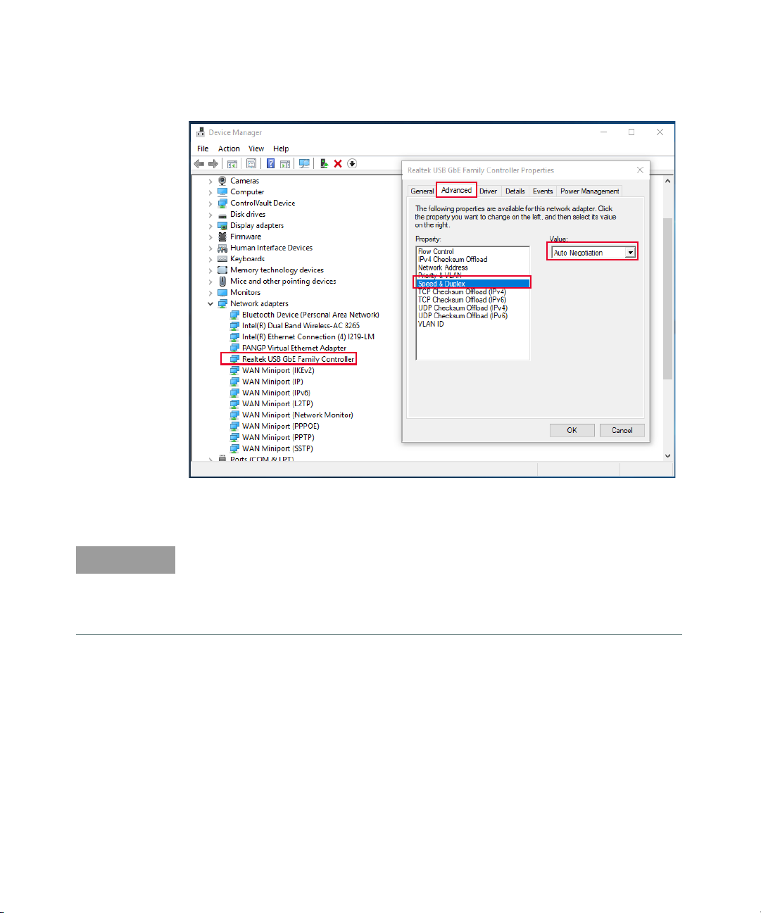
Configuring the Ethernet Port
For performing BER tests based on a data loopback analysis, it is necessary to
configure the used Ethernet port of your PC (or the USB-to-Ethernet-adapter) in
the right way:
– The conversion by the APM1000E from Standard Ethernet to Automotive
Ethernet will fail if there is a change of the device speed or duplex setting in
the data flow.
– For tests at 100 Mbps, you must set the PC's Ethernet device (or the used
USB-to-Ethernet-adapter) to 100 Mbps Full Duplex:
Figure 3-9 Configuring the PC’s Ethernet Device for Tests at 100 Mbps
– In the same way, set the Ethernet device to “Auto Negotiation” for the tests at
1000 Mbps:
32 Keysight AE6910R Automotive Ethernet Rx Compliance Test Software Installation & User Guide
Page 33
ValiFrame Automotive Ethernet Software 3
NOTE
Figure 3-10 Configuring the PC’s Ethernet Device for Tests at 1000 Mbps
If the device is currently at 1000 Mbps and you want to switch it to 100 Mbps,
then you need to change the device's Speed & Duplex to “100 Mbps Full Duplex”
and press the Master/Slave button at the device until flash light change to
yellow. Next, you need to reconnect the USB cable of the device to ensure it
works properly on data loopback analysis.
Keysight AE6910R Automotive Ethernet Rx Compliance Test Software Installation & User Guide 33
Page 34
3 ValiFrame Automotive Ethernet Software
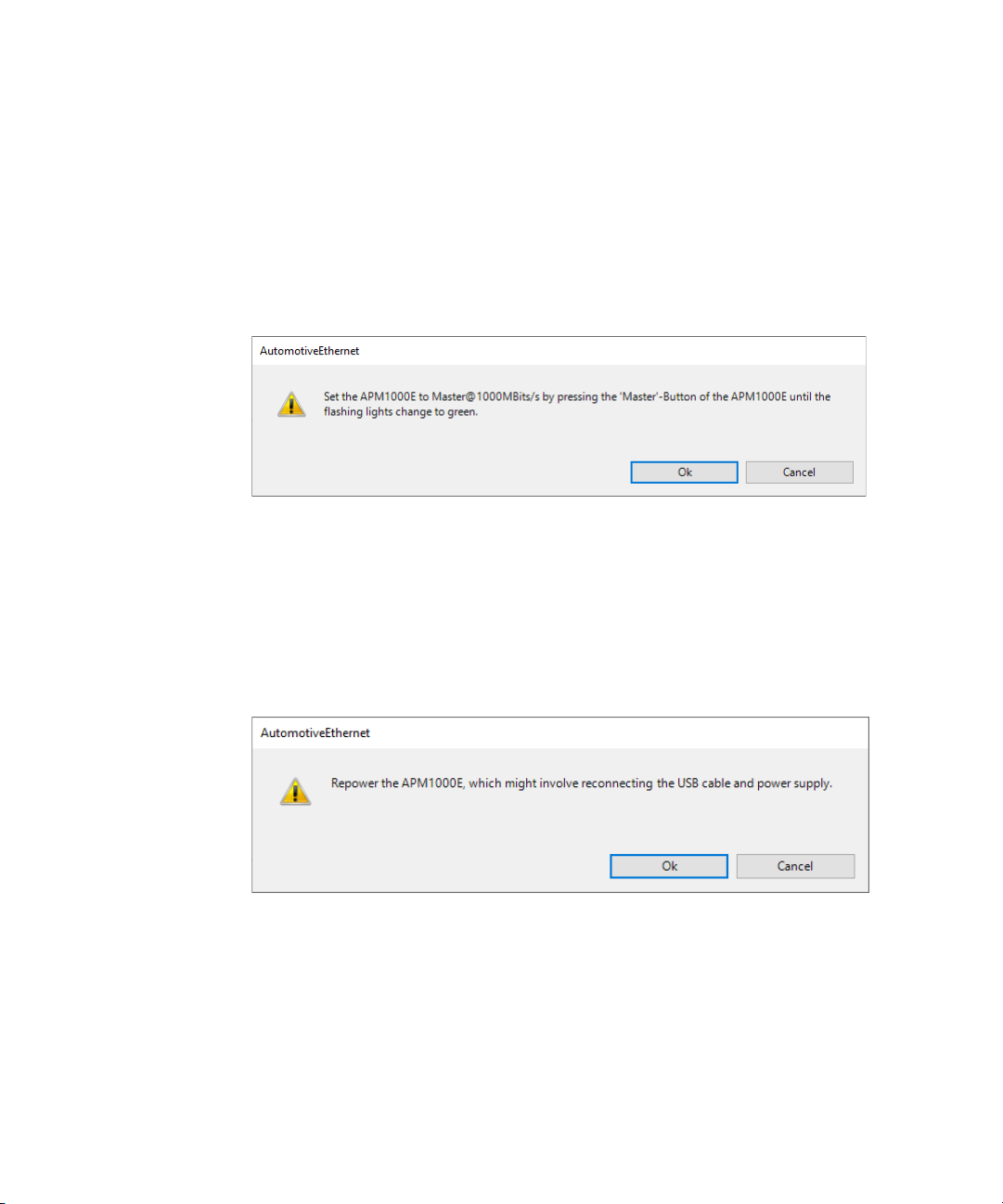
Configuring Data Rate and Link Role of the APM1000E
The APM1000E has to be configured correctly, depending on the chosen data rate
and link role of the DUT.
If ValiFrame detects a wrong configuration, it displays a dialog with the direction
of the button to press. The dialog will appear again for as long as the
configuration of the APM1000E is incorrect.
Figure 3-11 Ensuring the Correct Data Rate and Link Role of the APM1000E
Using an APM1000E with Variable Clock Frequency
The internal clock of the APM1000E is only correctly working if the external
reference clock provided by the 81160A generator is present during startup. A
repowering step ensures this at the beginning of a test run and after changing the
clock frequency.
Figure 3-12 Ensuring the Initialization of the Internal Clock
34 Keysight AE6910R Automotive Ethernet Rx Compliance Test Software Installation & User Guide
Page 35

Keysight AE6910R Automotive Ethernet Rx Compliance Test
Software
Installation & User Guide
4 Using the Software
Overview 36
Selecting, Modifying, and Running Test 38
Results 40
Automotive Ethernet Parameters 42
35
Page 36

4Using the Software
Overview
Once you configured the DUT as detailed in the “Configuring the DUT” on
page 29, press the OK button in Configure DUT Panel. All the calibration and test
procedures are in their respective groups, organized in a similar way as in the CTS.
Figure 4-1 Automotive Ethernet Main Window
Use the Properties and Log List buttons of the main menu (highlighted in
Figure 4-1) to display additional information on the right and at the bottom of the
AE6910R main window, respectively. The parameter grid on the right side of the
window shows the parameters which are related to the selected calibration, test
procedure subgroups, or individual procedures. You can set these parameters only
before the execution of the procedure subgroup or before starting the procedure.
The log list at the bottom of the window shows calibration and test status
messages (regular progress updates as well as warnings and error messages).
Upon running all the procedures, the AE6910R configuration can be stored as a
single “.vfp” file using the Save button and recalled using the Load button without
configuring the DUT again.
36 Keysight AE6910R Automotive Ethernet Rx Compliance Test Software Installation & User Guide
Page 37

Using the Software 4
CAUTION
Before executing the calibration or test procedures, ensure that you
configure the Automotive Ethernet Station Configuration properly with all
necessary instruments such as the Infiniium oscilloscope set to “online”. You
can run all calibrations in offline mode, that is, without any instruments
connected. The offline mode is for product demonstrations with simulated
data. CALIBRATIONS RUN IN OFFLINE MODE DO NOT GENERATE VALID
CALIBRATION DATA.
Keysight AE6910R Automotive Ethernet Rx Compliance Test Software Installation & User Guide 37
Page 38

4Using the Software
Selecting, Modifying, and Running Test
Selecting Procedures
The calibration, receiver, and transmitter test procedure groups can be selected
globally by clicking on the checkbox at the top of the group. Alternatively, you can
select an individual test procedure by checking the specific selection boxes in
front of the tests. Click on the Start button to execute the selected test
procedures.
Modifying Parameters
Most calibration and test procedures, as well as the groups containing them, have
parameters that control the details of how to run these procedures. In the
compliance mode, most of these parameters are read-only. In the expert mode,
you can modify almost all parameters. First, select a specific calibration or test
procedure or one of the groups containing in the AE6910R procedure tree (see
Figure 4-2). The displayed parameters are in a property list on the right side of the
screen. If they are not displayed, press the Properties button. Your selection on
the top left side of the list determines if the list is ordered alphabetically or in
categories. The test parameters selected are listed in the MS Excel/HTML test
results worksheets.
38 Keysight AE6910R Automotive Ethernet Rx Compliance Test Software Installation & User Guide
Page 39

Figure 4-2 Modifying Parameters
Using the Software 4
Running Procedures
To run the selected procedure or test, press the Start button (highlighted in
Figure 4-1). The procedures run in the order shown in the procedure selection
tree. Some procedures may require user interaction, such as changing cable
connections or entering DUT parameters. The required action is prompted in
pop-up dialog boxes before the execution.
The connection diagram is also displayed by right-clicking on the desired test or
calibration and selecting Show Connection....
Keysight AE6910R Automotive Ethernet Rx Compliance Test Software Installation & User Guide 39
Page 40

4Using the Software
NOTE
Results
Run-Time Data Display
Most procedures generate data output. While the procedure is running, the data
displays in a temporary MS Excel worksheet or HTML page (depending on the
selected viewer in the Station), which opens automatically for each procedure.
The MS-Excel worksheet or the HTML page opened during the procedure run
then are closed once the specific procedure is complete. As long as the AE6910R
software is running, you can reopen each worksheet or page by double-clicking
on the respective procedure. However, the individual worksheets or pages will be
lost when the AE6910R main window is closed unless you saved them.
Results Workbook
You can save all calibration and test data worksheets in a workbook by selecting
File > Save Results as Workbook... at any time. Keysight recommends that this
step is carried out at least at the end of each AE6910R run. If the calibration and
test procedures are conducted several times during the same AE6910R run, the
result worksheets are combined in the workbook. If you conduct a test procedure
without prior execution of calibration procedures in the same test run, only the
test results will be saved to the workbook.
As a safety feature, all calibration and test results are saved by default to the
ValiFrame “Tmp” directory. The sub-folder “Results/IEEE Open Station” contains
the Excel files of the final results measured at each calibration and test
procedure.
In addition to the calibration data worksheets, the calibration data files are
generated. These files are saved by default to the ValiFrame calibrations folder.
Rerunning these calibrations will overwrite the data file. To save the calibration
data files at each configuration, you must copy the files from the directory:
“C:\ProgramData\BitifEye\ValiFrameK1\Automotive Ethernet\Calibrations” and
save them manually in any folder before rerunning the calibrations.
40 Keysight AE6910R Automotive Ethernet Rx Compliance Test Software Installation & User Guide
Page 41

Test Results
Once you run the selected procedures successfully, a smiley face indicates the
results (Pass / Fail / Incomplete), as shown in Table 4-1.
Table 4-1 Test Result Description
Smiley Description
Using the Software 4
Indicates that the procedure passed successfully in the previous run and the results are
available.
Indicates that the procedures passed in offline mode previously, and the results are
available.
Indicates that the procedure passed successfully in the present run.
Indicates that the procedure did not run completely in the previous run.
Indicates that the procedure could not run in the present run. Most likely, the DUT failed
during initialization, so there was no test conducted.
Indicates that the procedure failed in the previous run.
Indicates that the procedure failed in the present run.
This smiley face displays two results, such as the first half indicating the result of the
present run and the second half showing the result of the previous run. In this example, the
first half indicates that the procedure passed successfully in the present run and the
second half means that it did not completely run in the previous run.
Keysight AE6910R Automotive Ethernet Rx Compliance Test Software Installation & User Guide 41
Page 42
4Using the Software
Automotive Ethernet Parameters
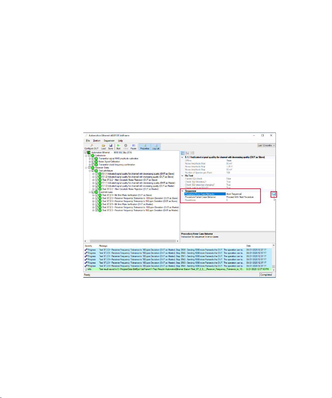
Sequencer Parameters
The sequencer parameters control the flow of the test sequencer, not the behavior of
individual procedures. They are identical across all versions of ValiFrame. One of them,
Repetitions, is available for all procedures and groups in the procedure tree. The others are
only available for procedures. Like all other parameters, the sequencer parameters are
shown on the right side of the ValiFrame user interface, and they can be changed by the
user, as illustrated in Figure 4-3.
Figure 4-3 Sequencer Parameters
42 Keysight AE6910R Automotive Ethernet Rx Compliance Test Software Installation & User Guide
Page 43

Using the Software 4
Table 4-2 lists all sequencer parameters in alphabetical order.
Table 4-2 Automotive Ethernet Sequencer Parameters
Parameter Name Parameter Description
“Proceed With Next Procedure”: If an error occurs in the current test
Procedure Error Case Behavior
Procedure Failed Case Behavior
Repetitions
or calibration procedure, continue by running the next procedure in
the sequence.
“Abort Sequence”: Abort the execution of the sequence.
“Proceed With Next Procedure”: If the current test or calibration
procedure fails, continue by running the next procedure in the
sequence.
“Abort Sequence”: Abort the execution of the sequence.
The number of times the group or procedure is going to be repeated.
If the value is “0”, it runs only once.
Keysight AE6910R Automotive Ethernet Rx Compliance Test Software Installation & User Guide 43
Page 44

4Using the Software
Common Parameters
The common parameters are used for several related calibrations or test
procedures. They are shown on the right side of the ValiFrame user interface when
the selected entry of the procedure tree on the left is a group instead of an
individual procedure.
The Automotive Ethernet Receiver Test Software has some group parameters (in
addition to Repetitions) on the top-level entry of the Receiver procedure tree, as
shown Figure 4-4. These will be common for all ValiFrame receiver procedures.
Figure 4-4 Common Parameters
44 Keysight AE6910R Automotive Ethernet Rx Compliance Test Software Installation & User Guide
Page 45

Procedure Parameters
The Procedure Parameters are all parameters that do not fall into one of the
previously described categories. They are shown on the right side of the ValiFrame
user interface when the selected entry of the procedure tree on the left is an
individual procedure. They only change the behavior of that single procedure.
Procedures often have parameters with the same name, but set settings always
apply to the selected procedure, and the meaning may be slightly different.
Using the Software 4
Keysight AE6910R Automotive Ethernet Rx Compliance Test Software Installation & User Guide 45
Page 46

4Using the Software
THIS PAGE HAS BEEN INTENTIONALLY LEFT BLANK.
46 Keysight AE6910R Automotive Ethernet Rx Compliance Test Software Installation & User Guide
Page 47

Keysight AE6910R Automotive Ethernet Rx Compliance Test
Software
Installation & User Guide
5 Calibrations
Overview 48
Transmitter Signal RMS Amplitude Calibration 49
Noise Signal Calibration 52
Transmitter Clock Frequency Confirmation 57
47
Page 48

5Calibrations
NOTE
Overview
Before running any receiver test procedure, the Automotive Ethernet receiver test
system must first be calibrated.
The DUT input ports give the ValiFrame calibration plane. The receiver test signal
characteristics are typically affected by the signal transmission between the
generator output ports and the DUT input ports. Thus, for any signal output
parameter selected by the user (set value), the signal received at the DUT input
ports (actual value) deviates from the set value. The ValiFrame calibration
procedures compensate these deviations of the relevant signal output parameter
actual values from the set values over the required parameter range.
The ValiFrame software includes all calibration procedures required for
Automotive Ethernet receiver testing. The implemented ValiFrame calibration
procedures are such that the calibration process is conducted as fast as possible
and is automated as much as possible; for example, by minimizing the number of
reconfigurations of the hardware connections.
The LED color of the APM1000E-CLK changes to Magenta if Ext is selected and if
it is not connected to the external clock.
To change the LED color to blue, connect the APM1000E-CLK to the external
clock and repower the device. If the APM1000E-CLK is not connected to the
external clock, ensure the Int is selected and hold Master button while powering
up the device.
48 Keysight AE6910R Automotive Ethernet Rx Compliance Test Software Installation & User Guide
Page 49

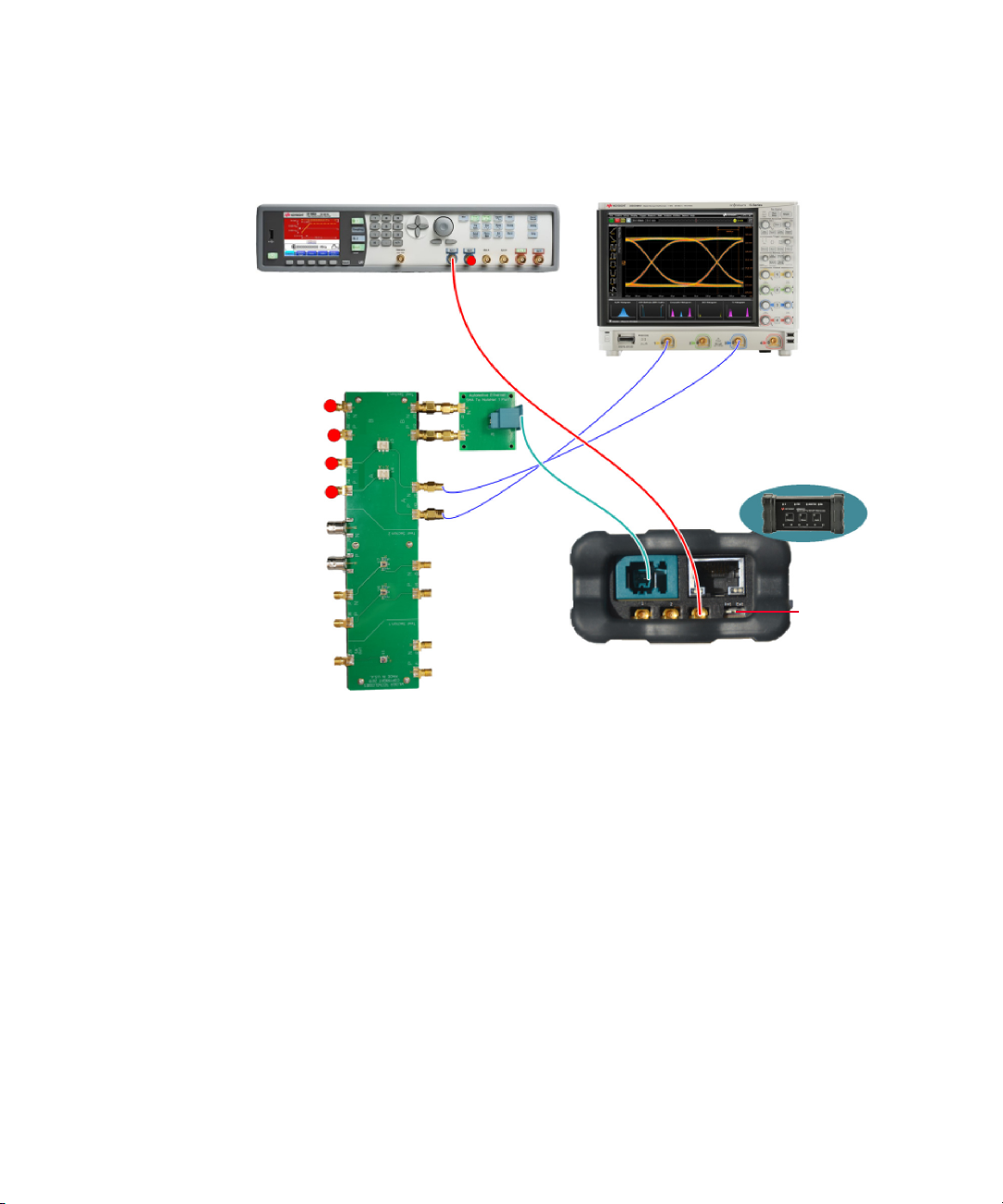
Transmitter Signal RMS Amplitude Calibration
MSOS804A Infiniium
S-Series Oscilloscope
AE6941A Automotive
Ethernet Test Fixture
AE6943A
Automotive
Ethernet
SMA to
MATEnet
APM1000E-CLK
100/1000BASE-T1
Media Converter
Purpose and Method
The purpose of this procedure is to measure the voltage amplitude of the
APM1000E signal generator.
The test automation sets the signal generator into a defined mode (Testmode5)
and measures the RMS amplitude of the output signal after the fixture with a
real-time oscilloscope.
Use the measured value in the following calibration (Noise Signal Calibration).
Assigned to the “Measured Tx Signal RMS” parameter, use it to calculate the
signal to noise ratio (SNR).
Connection Diagram
Calibrations 5
Figure 5-1 Connection Diagram for Transmitter Signal Peak-Peak
Calibration
Keysight AE6910R Automotive Ethernet Rx Compliance Test Software Installation & User Guide 49
Page 50
5Calibrations
AE6941A Automotive
Ethernet Test Fixture
81160A Pulse Function Arbitrary Noise Generator
MSOS804A Infiniium
S-Series Oscilloscope
AE6943A
Automotive
Ethernet SMA to
MATEnet
APM1000E-CLK
100/1000BASE-T1
Media Converter
Switch to Ext
Figure 5-2 Connection Diagram for Transmitter Signal Peak-Peak
Parameters in Expert Mode
Scope
– Number of UI to acquire: Scope capture length in Unit Intervals.
– Scope Bandwidth: Bandwidth set on the scope.
– Time Base Scale of the scope: Time base scale set on the scope.
50 Keysight AE6910R Automotive Ethernet Rx Compliance Test Software Installation & User Guide
Calibration (with External Clock)
Page 51

Result Description
Figure 5-3 Example HTML Viewer for Transmitter Signal Peak-Peak
– Measured Tx-Signal RMS [mV]: The RMS voltage amplitude measured on the
scope.
Calibrations 5
Amplitude Calibration
Keysight AE6910R Automotive Ethernet Rx Compliance Test Software Installation & User Guide 51
Page 52

5Calibrations
Noise Signal Calibration
Purpose and Method
The purpose of this procedure is to calibrate the noise and the signal to noise ratio
(SNR) of the setup.
The test automation starts by applying small noise amplitudes and increases them
with the defined step size. For every set value, measure the noise amplitude with a
real-time oscilloscope and, calculate the SNR for the given “Measured Tx-Signal
RMS”. Repeat until you reach the target SNR (or until the maximum capability of
the noise generator).
52 Keysight AE6910R Automotive Ethernet Rx Compliance Test Software Installation & User Guide
Page 53

MSOS804A
Infiniium
S-Series
Oscilloscope
AE6941A
Automotive
Ethernet Test
Fixture
81160A Pulse Function Arbitrary Noise Generator
Calibrations 5
Connection Diagram
Figure 5-4 Connection Diagram for SNR Calibration
Keysight AE6910R Automotive Ethernet Rx Compliance Test Software Installation & User Guide 53
Page 54

5Calibrations
NOTE
Parameters in Expert Mode
Generator
– Measured Tx-Signal RMS: Set to the measured value from the previous
calibration.
Noise
– Noise Bandwidth: Bandwidth of the noise signal.
– Noise CrestFactor: The crest factor of the noise injected to the signal.
– Noise Amplitude Step Size: The amount of noise amplitude increased at each
step.
– First Set Noise Amplitude: The noise amplitude set at the first step.
– Target Signal Noise Ratio: The target SNR. The calibration will finish when the
measured SNR is smaller than that value.
Scope
– Number of UI to acquire: Scope capture length in Unit Intervals.
– Scope Bandwidth: Bandwidth set on the scope.
– Time Base Scale of the Scope: Time base scale set on the scope.
The scope settings are recommended to get quick and reliable measurement
results.
The noise settings are defined in the test specifications
Dependencies
– Transmitter signal RMS amplitude calibration.
54 Keysight AE6910R Automotive Ethernet Rx Compliance Test Software Installation & User Guide
Page 55

Result Description
Calibrations 5
Figure 5-5 Example HTML Viewer for Signal To Noise Ratio Calibration
Keysight AE6910R Automotive Ethernet Rx Compliance Test Software Installation & User Guide 55
Page 56

5Calibrations
– Set Noise Amplitude [mV]: The amplitude set on the noise generator.
– Measured Noise RMS [mV]: The measured noise in RMS.
– Signal to Noise Ratio [dB]: The measured SNR calculated with the measured
noise and the calibrated Tx-Signal RMS amplitude.
56 Keysight AE6910R Automotive Ethernet Rx Compliance Test Software Installation & User Guide
Page 57

Transmitter Clock Frequency Confirmation
Purpose and Method
The purpose of this procedure is to calibrate the transmitter clock frequency and
its deviation. It is available when you select the “External Clock” option in the
Station Configuration.
Calibrations 5
Figure 5-6 Select External Clock in the Station Configuration Window
The test automation does a swept of the crystal clock frequency. For each step,
measure the transmitter output frequency with a real-time oscilloscope.
The calibration passes if the output frequency range covers the range defined by
the “Mean transmitter out frequency” ± “Clock frequency deviation”.
Keysight AE6910R Automotive Ethernet Rx Compliance Test Software Installation & User Guide 57
Page 58

5Calibrations
MSOS804A Infiniium S-Series Oscilloscope
81160A Pulse Function Arbitrary Noise Generator
APM1000E-CLK
100/1000BASE-T1
Media Converter
Switch to Ext
Connection Diagram
Figure 5-7 Connection Diagram for Transmitter Clock Frequency
Parameters in Expert Mode
58 Keysight AE6910R Automotive Ethernet Rx Compliance Test Software Installation & User Guide
Generator
– Mean crystal frequency: The frequency of the external clock.
– Mean transmitter out frequency: The desired frequency for the signal output.
– Clock frequency deviation: The desired frequency deviation for the signal
output.
Confirmation
Page 59

Scope
– Number of UI to acquire: Scope capture length in Unit Intervals.
– Scope Bandwidth: Bandwidth set on the scope.
– Time Base Scale of the scope: Time base scale set on the scope.
Result Description
Calibrations 5
Figure 5-8 Example HTML Viewer for Transmitter Cock Frequency
Confirmation
Keysight AE6910R Automotive Ethernet Rx Compliance Test Software Installation & User Guide 59
Page 60

5Calibrations
– Crystal clock frequency [kHz]: The frequency set in the crystal clock.
– Transmitter output frequency [kHz]: The frequency measured on the
oscilloscope.
60 Keysight AE6910R Automotive Ethernet Rx Compliance Test Software Installation & User Guide
Page 61

Keysight AE6910R Automotive Ethernet Rx Compliance Test
Software
Installation & User Guide
6 Receiver Tests
Overview 62
5.1.1 Indicated Signal Quality for Channel With Decreasing Quality 63
5.1.2 Indicated Signal Quality for Channel with Increasing Quality 69
Test 97.2.2 - Alien Crosstalk Idle Pattern Rejection 73
Test 97.2.2 - Alien Crosstalk Noise Rejection 75
Test 97.2.1 - Bit Error Rate Verification 78
Test 97.2.3 - Receiver Frequency Tolerance to ±100ppm Deviation 82
61
Page 62

6 Receiver Tests
NOTE
NOTE
Overview
Run all tests with the device set as Master and as Slave.
For Rx tests, the real-time oscilloscope is not needed and can stay unconnected.
The device configuration is not automatic. You are required to implement the bat
scripts or set the device manually with an appropriate tool.
The LED color of the APM1000E-CLK changes to Magenta if Ext is selected and if
it is not connected to the external clock.
To change the LED color to blue, connect the APM1000E-CLK to the external
clock and repower the device. If the APM1000E-CLK is not connected to the
external clock, ensure the Int is selected and hold Master button while powering
up the device.
62 Keysight AE6910R Automotive Ethernet Rx Compliance Test Software Installation & User Guide
Page 63

Receiver Tests 6
5.1.1 Indicated Signal Quality for Channel With Decreasing Quality
Purpose and Method
The purpose of this test is to ensure that the PHY indicates a signal quality, having
decreasing values for a channel with increasing noise.
Either manually or through the scripts, the DUT is soft reset, configured to SLAVE/
MASTER and the loopback is enabled. The test automation starts by applying the
minimum noise amplitude and increases it at each step until the maximum value.
For every set value, the SQI value is measured 100 times and averaged.
The following 3 conditions must be fulfilled to pass the test:
– SQI value steadily and monotonic increases/decreases by one step each (the
SQI values are only valid if link-up condition is present)
– Link-up status remains for SQI values higher than 0
– There should be no link instabilities with intermittent link drops for SQI values
higher than 0.
The absolute SQI values may be different from the OPEN Alliance
recommendation in “Advanced_PHY_features_for_automotive_Ethernet”.
In Expert Mode, there are flags to bypass some of those requirements, if the SQI
implementation in the tested DUT differs from the test specification in
“OA_1000BASE-T1 InteroperabilityTest Suite” or
“OA_100BASE-T1_Interoperability_Test_Suite”.
Keysight AE6910R Automotive Ethernet Rx Compliance Test Software Installation & User Guide 63
Page 64
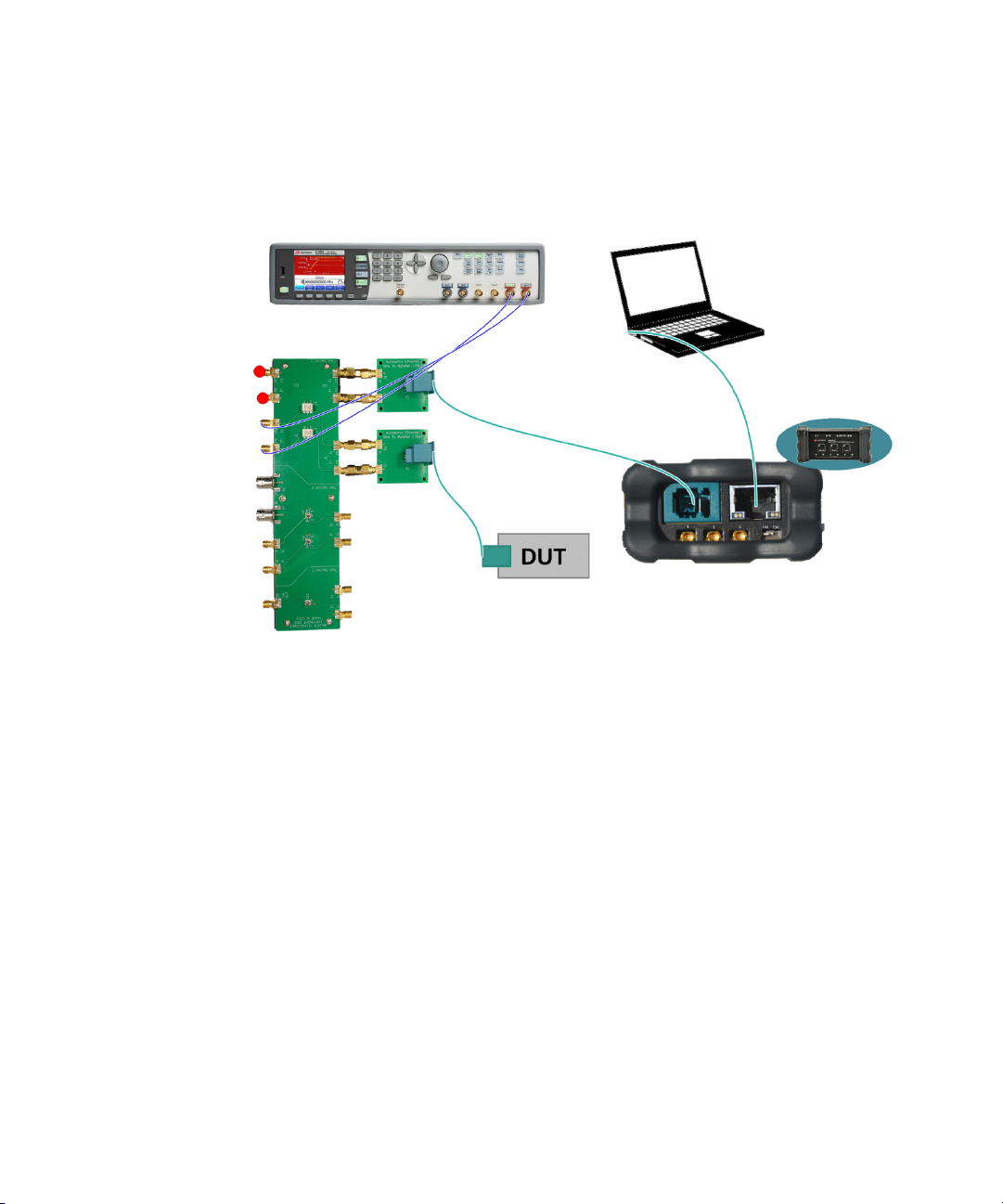
6 Receiver Tests
81160A Pulse Function Arbitrary
Noise Generator
AE6941A Automotive Ethernet Test Fixture
AE6943A
Automotive
Ethernet
SMA to
MATEnet
AE6943A Automotive
Ethernet SMA to MATEnet
APM1000E-CLK 100/1000BASE-T1
Media Converter
PC
Connection Diagram
Figure 6-1 Connection Diagram for Receiver Tests with Fixture
64 Keysight AE6910R Automotive Ethernet Rx Compliance Test Software Installation & User Guide
Page 65

Receiver Tests 6
81160A Pulse Function Arbitrary
Noise Generator
AE6941A Automotive Ethernet Test Fixture
AE6943A
Automotive
Ethernet
SMA to
MATEnet
AE6943A Automotive
Ethernet SMA to MATEnet
APM1000E-CLK 100/1000BASE-T1
Media Converter
PC
Switch
to Ext
NOTE
Figure 6-2 Connection Diagram for Receiver Tests with F ixture (wit h
Parameters in Expert Mode
Refer to Figure 5-6 to enable External Clock in the Station Configuration window.
– Noise Amplitude Start: The first noise amplitude value tested.
– Noise Amplitude Stop: The last noise amplitude value tested.
– Noise Amplitude Step: The amount that the amplitude noise decreases at
each step.
– Forced SQI check: If set to “False”, the SQI values are not queried from the
Keysight AE6910R Automotive Ethernet Rx Compliance Test Software Installation & User Guide 65
DUT at Link-Down state. If set to “True”, the SQI values are queried from the
External Clock)
Page 66

6 Receiver Tests
– Check SQI Monotony?: Check if SQI is steadily and monotonic decreasing.
– Check SQI stepwise changing?: Check if SQI values change by one step each.
– Check LinkUp at SQI >0?: Check if Link-up status remains for SQI values
– Number of Queries per Point: Number of times that the SQI value is requested
Dependencies
– Transmitter Signal RMS Amplitude Calibration
–Noise Signal Calibration
DUT 100 times per noise amplitude, even when the link is down. According to
the CTS, this is not necessary (and may need significantly extra test time).
higher than 0.
to the DUT for each noise amplitude tested.
66 Keysight AE6910R Automotive Ethernet Rx Compliance Test Software Installation & User Guide
Page 67
Result Description
Receiver Tests 6
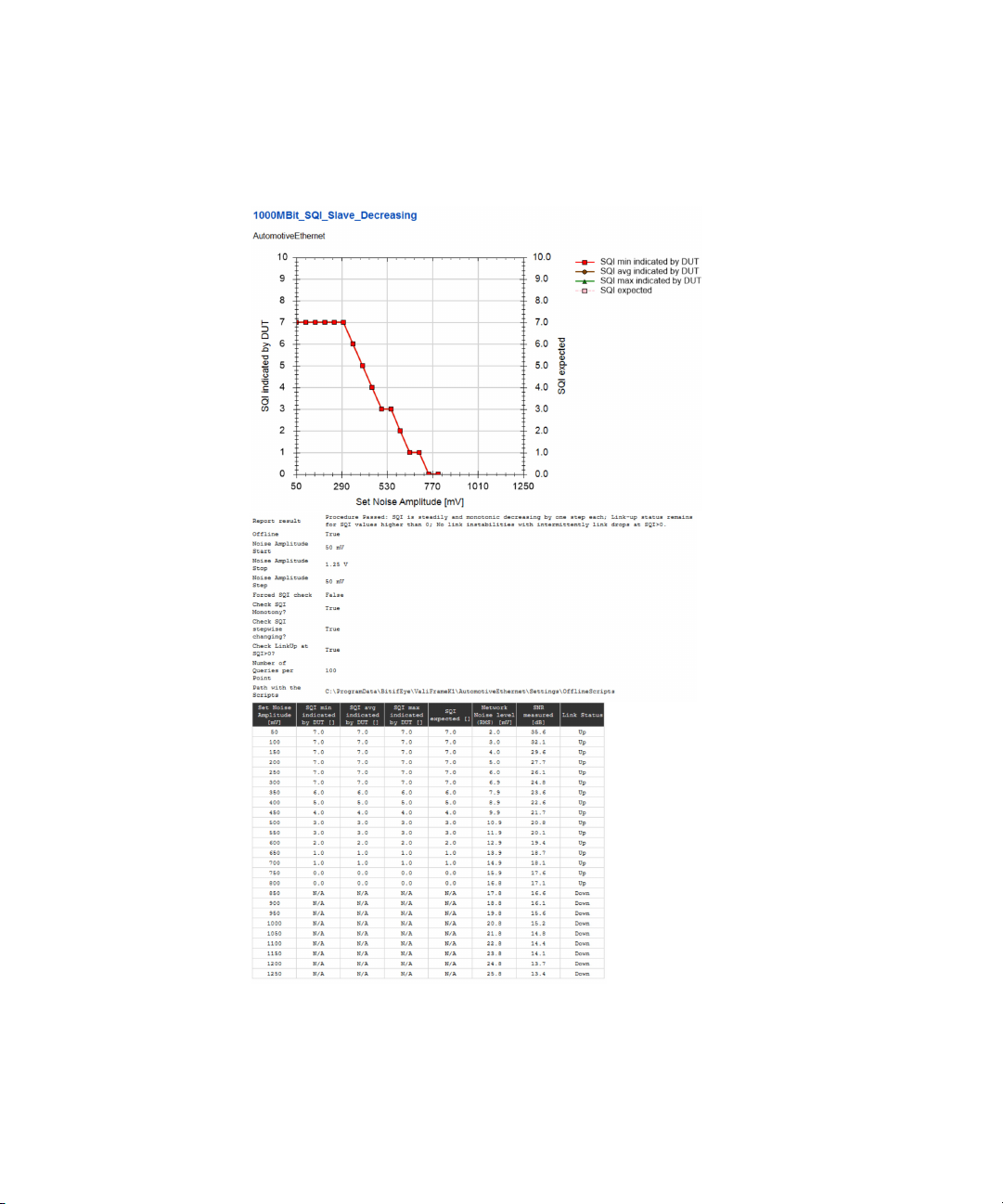
Figure 6-3 Example HTML Viewer for Indicated Signal Quality for Channel
With Decreasing Noise
Keysight AE6910R Automotive Ethernet Rx Compliance Test Software Installation & User Guide 67
Page 68

6 Receiver Tests
– Set Amplitude Noise [mV]: The noise amplitude applied to the signal at each
– SQI min indicated by DUT [ ]: The minimum SQI archived during that tested
– SQI avg indicated by DUT [ ]: The averaged SQI indicated by the DUT for the
– SQI max indicated by DUT [ ]: The maximum SQI archived during that tested
– SQI expected [ ]: The SQI expected for the tested point.
– Network Noise level (RMS) [mV]: The noise RMS measured on the Noise
– SNR measured [dB]: The SNR measured in the Noise Signal Calibration.
– Link Status: Down/Up.
Refer to Table 6-1 for The expected SQI values are calculated from the applied
noise (SNR), according to chapter 6.1.2 in the OpenAlliance specification
“Advanced_PHY_features_for_automotive_Ethernet”.
step.
point.
tested point.
point.
Signal Calibration for the tested point.
Table 6-1 Recommended correlation from SQI to SNR
SQI Value
0 <18 dB
2 19 dB ≤ SNR < 20 dB
3 20 dB ≤ SNR < 21 dB
4 21 dB ≤ SNR < 22 dB
5 22 dB ≤ SNR < 23 dB
6 23 dB ≤ SNR < 24 dB
7 24 dB ≤ SNR
SNR Value at MDI-AWG Noise, 80 MHz
(Informative)
Recommended BER for AWG Noise
Model (Informative)
BER > 10^-101 18 dB ≤ SNR < 19 dB
BER < 10^-10
68 Keysight AE6910R Automotive Ethernet Rx Compliance Test Software Installation & User Guide
Page 69

Receiver Tests 6
5.1.2 Indicated Signal Quality for Channel with Increasing Quality
Purpose and Method
The purpose of this test is to ensure that the PHY indicates a signal quality, having
increasing values for a channel with decreasing noise.
Either manually or through the scripts, the DUT is soft reset and configured to
SLAVE/MASTER. The test automation starts by applying the maximum noise
amplitude and decreases it at each step until the minimum value is reached. For
every set value, the SQI value is read from the DUT 100 times and averaged.
To pass the test, the Link Status must change from “Down” at high SNR to “Up” at
high SNR values.
The absolute SQI values may be different from the OPEN Alliance
recommendation in
“Advanced_PHY_features_for_automotive_Ethernet_V1.0_100MBase-T1”.
Connection Diagram
Refer to Figure 6-1 and Figure 6-2.
Keysight AE6910R Automotive Ethernet Rx Compliance Test Software Installation & User Guide 69
Page 70

6 Receiver Tests
Parameters in Expert Mode
– Noise Amplitude Start: The first noise amplitude value tested.
– Noise Amplitude Stop: The last noise amplitude value tested.
– Noise Amplitude Step: The amount that the amplitude noise increased at
– Forced SQI check: If set to “False”, the SQI values are not queried from the
– Check SQI Monotony?: Check if SQI is steadily and monotonic decreasing.
– Check SQI stepwise changing?: Check if SQI values change by one step each.
– Check LinkUp at SQI >0?: Check if Link-up status remains for SQI values
– Number of Queries per Point: Number of times that the SQI value is requested
Dependencies
–Noise Signal Calibration
each step.
DUT at Link-Down state. If set to “True”, the SQI values are queried from the
DUT 100 times per noise amplitude, even when the link is down. According to
the CTS, this is not necessary (and may need significantly extra test time).
higher than 0.
to the DUT for each noise amplitude tested.
70 Keysight AE6910R Automotive Ethernet Rx Compliance Test Software Installation & User Guide
Page 71

Result Description
Receiver Tests 6
Figure 6-4 Example HTML Viewer for Indicated Signal Quality for Channel
with Increasing Quality
Keysight AE6910R Automotive Ethernet Rx Compliance Test Software Installation & User Guide 71
Page 72

6 Receiver Tests
– Set Noise Amplitude [mV]: The noise amplitude applied to the signal at each
– SQI min indicated by DUT [ ]: The minimum SQI archived during that tested
– SQI avg indicated by DUT [ ]: The averaged SQI archived during that tested
– SQI max indicated by DUT [ ]: The maximum SQI archived during that tested
– SQI expected [ ]: The SQI expected for the tested point.
– Network Noise level (RMS) [mV]: The noise RMS measured on the Noise
– SNR measured [dB]: The SNR measured on the Noise Signal Calibration for
– Link Status: Down/Up.
step.
point.
point.
point.
Signal Calibration for the tested point.
the tested point.
72 Keysight AE6910R Automotive Ethernet Rx Compliance Test Software Installation & User Guide
Page 73

Test 97.2.2 - Alien Crosstalk Idle Pattern Rejection
Purpose and Method
Receiver Tests 6
The purpose of this procedure is to verify that the DUT can maintain a bit error
rate (BER) of less than 10
test, the noise source sends idle symbols. The level of the noise is 100 mV
peak-to-peak.
Either manually or through the scripts, configure the DUT to SLAVE/MASTER, and
the DUTs loopback is enabled. In case of testing in DUT access mode “Scripting”
without loopback, reset the Bit Error Counter and Frame Error Counter. Then the
test automation injects noise crosstalk to the signal, and the BER test starts.
The duration of the BER test will be the required time to reach a specified
confidence level (default: 95%). It depends on the capabilities of the PC and the
Ethernet Port. In very unlikely cases, it may take up to 2 hours.
If the looped back data differ from the sent out data, the faulty data packages are
counted as errors (or if the DUT reports transmission errors).
As long as the required amount of transferred bits is not reached, every error
causes the test to fail.
Connection Diagram
Refer to Figure 6-1 and Figure 6-2.
Parameters in Expert Mode
– Crosstalk Reference Amplitude: The peak-peak level of the crosstalk
reference.
– Target BitErrorRate: The target BER that determines if the test pass or not
– Target FrameErrorRate: The target FER that determines if the test pass or not
– Confidence Level: The confidence level used in the BER test
– Number of Frames per Step: The total BER measured in several steps. This
parameter determines the number of frames tested at each step.
– Required Number of Bits to send: The number of bits transmitted.
-10
in the presence of a crosstalk noise source. For this
Keysight AE6910R Automotive Ethernet Rx Compliance Test Software Installation & User Guide 73
Page 74

6 Receiver Tests
Dependencies
–Noise Signal Calibration
Result Description
Figure 6-5 Example HTML Viewer for Alien Crosstalk Idle Pattern Rejection
– Result: Pass/Fail. A pass means this test succeeded.
– Target BitErrorR ate: The target BER that determines if the test passes or fails.
– Target FrameErrorRate: The target FER that determines if the test passes or
fails.
– Confidence Level [%]: The confidence level of the BER test.
– Total sent bits [ ]: The number of tested bits.
– Total sent fr ames [ ]: The number of tested frames.
– Total received error bits [ ]: The total number of bit errors.
– Total received error frames [ ]: The total number of frame errors.
– BER measured on PHY: The BER indicated by the DUT.
– FER measured on PHY: The FER indicated by the DUT.
74 Keysight AE6910R Automotive Ethernet Rx Compliance Test Software Installation & User Guide
Page 75

Test 97.2.2 - Alien Crosstalk Noise Rejection
Purpose and Method
The purpose of this procedure is to verify that the DUT can maintain a bit error
-10
rate (BER) of less than 10
test, the noise source sends a Gaussian distribution signal with a bandwidth of
50 MHz and a magnitude of -85 dBm/Hz if you perform the test at a data rate of
100 Mbps. By performing the test at a data rate of 1000 Mbps, the noise
bandwidth is 550 MHz, and the magnitude is -100 dBm/Hz.
Either manually or through the scripts, configure the DUT to SLAVE/MASTER, and
the DUTs loopback is enabled. In case of testing in DUT access mode “Scripting”
without loopback, reset the Bit Error Counter and Frame Error Counter. The test
automation then injects noise crosstalk to the signal, and the BER test starts.
The duration of the BER test will be the required time to reach a specified
confidence level (default: 95%). It depends on the capabilities of the PC and the
Ethernet Port. In very unlikely cases, it may take up to 2 hours.
If the looped back data differ from the sent out data, the faulty data packages are
counted as errors (or if the DUT reports transmission errors).
in the presence of a crosstalk noise source. For this
Receiver Tests 6
As long as the required amount of transferred bits is not reached, every error
causes the test to fail.
Connection Diagram
Refer to Figure 6-1 and Figure 6-2.
Parameters in Expert Mode
– Noise Bandwidth: The bandwidth of the noise injected to the signal.
– Noise CrestFactor: The crest factor of the noise injected to the signal.
– Power density in dBm/Hz: The amount of power of the noise per frequency
interval.
– Target BitErrorRate: The target BER that determines if the test pass or not.
– Target FrameErrorRate: The target FER that determines if the test pass or not.
– Confidence Level: The confidence level used in the BER test.
Keysight AE6910R Automotive Ethernet Rx Compliance Test Software Installation & User Guide 75
Page 76
6 Receiver Tests
– Number of Frames per Step: The total BER measured in several steps. This
– Required Number of Bits to send: The number of bits transmitted.
Dependencies
–Noise Signal Calibration
Result Description
parameter determines the number of frames tested at each step.
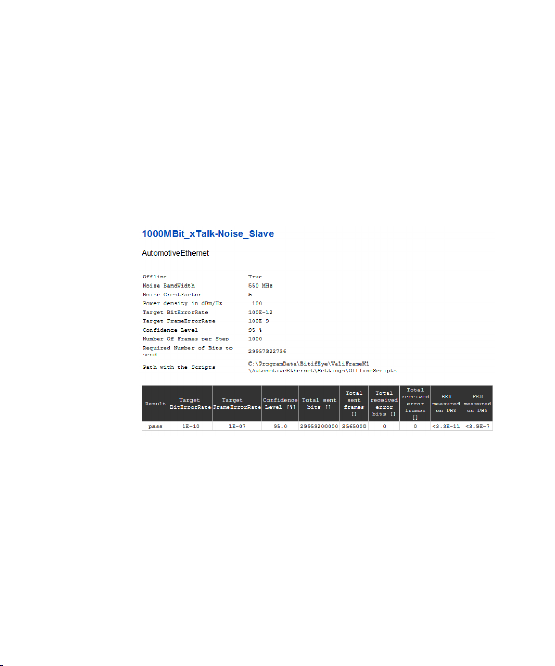
Figure 6-6 Example HTML Viewer for Alien Crosstalk Noise Rejection
– Result: Pass/Fail. A pass means this test succeeded.
– Target BitErrorR ate: The target BER that determines if the test passes or fails.
– Target FrameErrorRate: The target FER that determines if the test passes or
fails.
– Confidence Level [%]: The confidence level of the BER test.
– Total sent bits [ ]: The number of bits tested.
– Total sent fr ames [ ]: The number of frames tested.
76 Keysight AE6910R Automotive Ethernet Rx Compliance Test Software Installation & User Guide
Page 77

Receiver Tests 6
– Total received error bits [ ]: The total number of bit errors.
– Total received error frames [ ]: The total number of frame errors.
– BER measured on PHY: The BER indicated by the DUT.
– FER measured on PHY: The FER indicated by the DUT.
Keysight AE6910R Automotive Ethernet Rx Compliance Test Software Installation & User Guide 77
Page 78

6 Receiver Tests
Test 97.2.1 - Bit Error Rate Verification
Purpose and Method
The purpose of this procedure is to verify that the DUT can maintain a BER of less
-10
than 10
Either manually or through the scripts, configure the DUT to SLAVE/MASTER, and
the DUTs loopback is enabled. In case of testing in DUT access mode “Scripting”
without loopback, reset the Bit Error Counter and Frame Error Counter. The test
automation then injects noise crosstalk to the signal, and the BER test starts.
The duration of the BER test will be the required time to reach a specified
confidence level (default: 95%). It depends on the capabilities of the PC and the
Ethernet Port. In very unlikely cases, it may take up to 2 hours.
If the looped back data differ from the sent out data, the faulty data packages are
counted as errors (or if the DUT reports transmission errors).
As long as the required amount of transferred bits is not reached, every error
causes the test to fail.
, while having maximum channel length attached.
Connection Diagram
Run the test with the required cable length (typically 15 m twisted pair, as defined
in IEEE Std 802.3bp).
78 Keysight AE6910R Automotive Ethernet Rx Compliance Test Software Installation & User Guide
Page 79

Receiver Tests 6
Length:
channel type
A or B
APM1000E-CLK 100/
1000BASE-T1 Media Converter
PC
PC
APM1000E-CLK 100/
1000BASE-T1 Media Converter
Length:
channel type
A or B
81160A Pulse Function Arbitrary
Noise Generator
Switch to Ext
NOTE
Figure 6-7 Connection Diagram for Receiver Tests with Direct Link
Keysight AE6910R Automotive Ethernet Rx Compliance Test Software Installation & User Guide 79
Figure 6-8 Connection Diagram for Receiver Tests with Direct Link (with
External Clock)
Refer to Figure 5-6 to enable External Clock in the Station Configuration window.
Page 80

6 Receiver Tests
Parameters in Expert Mode
– Target BitErrorR ate: The target BER that determines if the test passes or not.
– Target FrameErrorRate: The target FER that determines if the test passes or
– Confidence Level: The confidence level used in the BER test.
– Number of Frames per Step: The total BER is measured in several steps. This
– Required Number of Bits to send: The number of bits transmitted.
not.
parameter determines the number of tested frames at each step.
80 Keysight AE6910R Automotive Ethernet Rx Compliance Test Software Installation & User Guide
Page 81
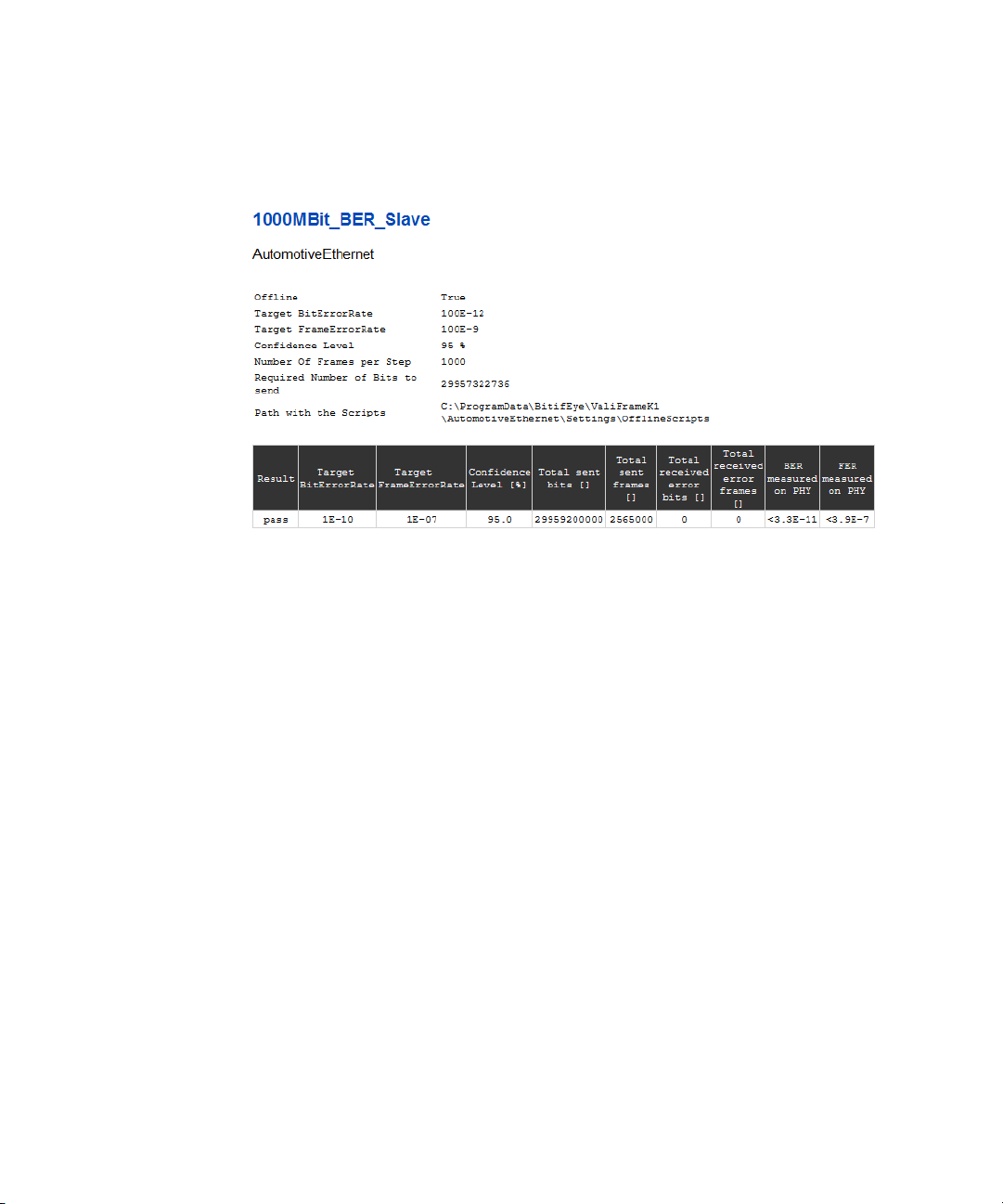
Result Description
Figure 6-9 Example HTML Viewer for Bit Error Rate Verification
– Result: Pass/Fail. A pass means this test succeeded.
– Target BitErrorRate: The target BER that determines if the test passes or fails.
Receiver Tests 6
– Target FrameErrorRate: The target FER that determines if the test passes or
fails.
– Confidence Level [%]: The confidence level of the BER test.
– Total sent bits [ ]: The number of tested bits.
– Total sent frames [ ]: The number of tested frames.
– Total received error bits [ ]: The total number of bit errors.
– Total received error frames [ ]: The total number of frame errors.
– BER measured on PHY: The BER indicated by the DUT.
– FER measured on PHY: The FER indicated by the DUT.
Keysight AE6910R Automotive Ethernet Rx Compliance Test Software Installation & User Guide 81
Page 82

6 Receiver Tests
NOTE
NOTE
Test 97.2.3 - Receiver Frequency Tolerance to ±100ppm Deviation
This test will only be available if you select the “External Clock” option on the
Station Configuration. Refer to Figure 5-6 to enable External Clock in the Station
Configuration window.
The 100BASE-T1 only has test procedures for 97.2.3 - Receiver Frequency
Tolerance to ±100ppm Deviation for DUT as Slave.
Purpose and Method
The purpose of this procedure is to verify that the DUT can properly accept
incoming data at a symbol rate deviation of ±100 ppm.
Either manually or through the scripts, configure the DUT to SLAVE/MASTER, and
the DUTs loopback is enabled. In case of testing in DUT access mode “Scripting”
without loopback, reset the Bit Error Counter and Frame Error Counter. The test
automation then injects noise crosstalk to the signal, and the BER test starts.
The duration of the BER test will be the required time to reach a specified
confidence level (default: 95%). It depends on the capabilities of the PC and the
Ethernet Port. In very unlikely cases, it may take up to 2 hours.
If the looped back data differ from the sent out data, the faulty data packages are
counted as errors (or if the DUT reports transmission errors).
As long as the required amount of transferred bits is not reached, every error
causes the test to fail.
Connection Diagram
Refer to Figure 6-7 and Figure 6-8.
82 Keysight AE6910R Automotive Ethernet Rx Compliance Test Software Installation & User Guide
Page 83

Parameters in Expert Mode
– Symbol Rate: The symbol rate of the data output signal.
– FrequencyDeviation: The deviation added to the symbol rate of the data
output signal.
– Target BitErrorRate: The target BER that determines if the test pass or not.
– Target FrameErrorRate: The target FER that determines if the test pass or not.
– Confidence Level: The confidence level used in the BER test.
– Number of Frames per Step: The total BER measured in several steps. This
parameter determines the number of frames tested at each step.
– Required Number of Bits to send: The number of bits transmitted.
Receiver Tests 6
Figure 6-10 Example HTML Viewer for Bit Error Rate Verification for Receiver
Frequency Tolerance to +100ppm Deviation
– Result: Pass/Fail. It passes if the measured BER is less than the Target BER.
Otherwise, it fails.
– Target BitErrorRate: The target BER that determines if the test passes or fails.
– Target FrameErrorRate: The target FER that determines if the test passes or
fails.
Keysight AE6910R Automotive Ethernet Rx Compliance Test Software Installation & User Guide 83
Page 84

6 Receiver Tests
– Confidence Level [%]: The confidence level of the BER test.
– Total sent bits [ ]: The number of bits tested.
– Total sent fr ames [ ]: The number of frames tested.
– Total received error bits [ ]: The total number of bit errors.
– Total received error frames [ ]: The total number of frame errors.
– BER measured on PHY: The BER indicated by the DUT.
– FER measured on PHY: The FER indicated by the DUT.
84 Keysight AE6910R Automotive Ethernet Rx Compliance Test Software Installation & User Guide
Page 85

Keysight AE6910R Automotive Ethernet Rx Compliance Test
Software
Installation & User Guide
7 Scripting
Scripting Details 86
85
Page 86

7Scripting
Scripting Details
To run all the tests automatically, ValiFrame controls the DUT by calling batch
scripts.
These scripts are called at special points of the test sequence. Each script has a
specific name reported in ValiFrame Logging-Window.
Some scripts are used to set the DUT into a specific state (e.g.
Enable_LoopBack.bat or Set_LinkRole_Master.bat). Others are expected to return
a value (e.g. Read_SQI.bat), which is read out of the DUT's PMA control registers.
You can implement any suitable logic inside those scripts (calling an executable,
calling a Python or a Tcl script …).
For some chip types, there are available ready-to-use automation scripts, which
can be accessed directly by the Valiframe Automotive Ethernet Test automation.
Contact the local Keysight support to get more information.
The called scripts for data rate 1000 Mbps are as follows:
Table 7-1 Scripts for 1000 Mbps
Procedure Standard-Method Script-Method Loopback-Method
SQI-Test
Alien-Crosstalk Noise
Alien-Crosstalk Idle
BER test
Frequency Deviation test
– Read_SQI.bat
– Reset_DeviceSoft.bat
– Set_LinkRole_Slave.bat
– Set_LinkRole_Master.bat
– Set_LinkRole_Master.bat
– Set_LinkRole_Slave.bat
– Enable_Loopback.bat
– Disable_Loopback.bat
– Read_SQI.bat
– Reset_DeviceSoft.bat
– Set_LinkRole_Slave.bat
– Set_LinkRole_Master.bat
– Set_LinkRole_Master.bat
– Set_LinkRole_Slave.bat
– Reset_ErrorCounter.bat
– Read_ErrorCounter.bat
86 Keysight AE6910R Automotive Ethernet Rx Compliance Test Software Installation & User Guide
Page 87

Scripting 7
For data rate 100 Mbps, different scripts are used, since the register addresses
may differ from those in 1000 Mbps mode:
Table 7-2 Scripts for 100 Mbps
Procedure Standard-Method Script-Method Loopback-Method
SQI-Test
– Read_SQI_100M.bat
– Reset_DeviceSoft_100M.bat
– Set_LinkRole_Slave_100M.bat
– Set_LinkRole_Master_100M.bat
– Read_SQI_100M.bat
– Reset_DeviceSoft_100M.bat
– Set_LinkRole_Slave_100M.bat
– Set_LinkRole_Master_100M.bat
Alien-Crosstalk Noise
Alien-Crosstalk Idle
BER test
Frequency Deviation test
– Set_LinkRole_Master_100M.bat
– Set_LinkRole_Slave_100M.bat
– Enable_Loopback_100M.bat
– Disable_Loopback_100M.bat
– Set_LinkRole_Master_100M.bat
– Set_LinkRole_Slave_100M.bat
– Reset_ErrorCounter_100M.bat
– Read_ErrorCounter_100M.bat
Keysight AE6910R Automotive Ethernet Rx Compliance Test Software Installation & User Guide 87
Page 88

7Scripting
THIS PAGE HAS BEEN INTENTIONALLY LEFT BLANK.
88 Keysight AE6910R Automotive Ethernet Rx Compliance Test Software Installation & User Guide
Page 89

Keysight AE6910R Automotive Ethernet Rx Compliance Test
Software
Installation & User Guide
8 Frame Generator
Overview 90
Connecting to the Instruments 90
Main User Interface 93
89
Page 90

8Frame Generator
Overview
The AE Frame Generator is a flexible tool for troubleshooting and debugging, that
complements the ValiFrame Station. It allows you to observe the response of the
DUT after sending frames with noise signal injected.
The AE Frame Generator controls the DUT automatically through calling the
required batch scripts (see “Scripting Details” on page 86).
Figure 8-1 AE Frame Generator
Connecting to the Instruments
After starting the Automotive Ethernet FrameGenerator, the software is in “offline”
mode. This mode means that the user input has no effect on the software until
connected to the instruments. Click the Instrument Connections button (see
Figure 8-2) to open the connection dialog. This action allows all the necessary
parameters entered to establish the connections to the signal generator and
complementary instruments.
90 Keysight AE6910R Automotive Ethernet Rx Compliance Test Software Installation & User Guide
Page 91

Frame Generator 8
Figure 8-2 Main Window (Instruments Disconnected)
In the ConnectionDialog window (see Figure 8-3), configure the test instrument
setup.
Media Converter
Generate the Frames to test from a Gigabit Ethernet port of a CPU or laptop. A
media converter is required to convert the Gigabit standard Ethernet to
Automotive Ethernet.
The Automotive Ethernet FrameGenerator uses the APM1000E as a media
converter. The media converter is always connected to a local USB3 port of the
PC.
Select the “External Clock” option to operate with an adjustable clock frequency.
In the Data Connection option, select the Ethernet Device used to generate the
Gigabit Ethernet frames.
Keysight AE6910R Automotive Ethernet Rx Compliance Test Software Installation & User Guide 91
Page 92
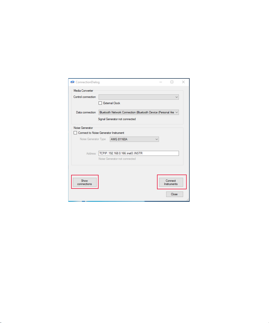
8Frame Generator
Noise Source
Select the instrument to inject noise into the channel and set the address. The
software supports the following sources:
– AWG 81160A
Figure 8-3 Instrument Connection Dialog
Once the configuration settings are done, click the Connect Instruments button.
If the connections are successful, the Connect button will become a Disconnect
button.
Click on the Show connections button to see the details of the required
connection diagram.
92 Keysight AE6910R Automotive Ethernet Rx Compliance Test Software Installation & User Guide
Page 93

Main User Interface
After the successful connection to the instruments, go back to the main window
(see Figure 8-2).
The window consists of the following sections:
–Data Rate
– Noise Settings
– Clock Frequency Deviation
–Transmit Frames
Data Rate
Select the data rate to test. 100MBASE-T1 and 1000MBASE-T1 are supported.
Select the product type as Master or Slave.
Noise Settings
This section allows you to define the noise signal injected to the DUT.
Frame Generator 8
Figure 8-4 Noise Settings
Click the Generate Noise button to initialize and configure the noise generator
instrument according to the selected noise bandwidth and amplitude.
You can choose the fine-scaled slider to control the noise amplitude more
precisely.
The Enable/Disable button will enable/disable the output of the noise generator.
Keysight AE6910R Automotive Ethernet Rx Compliance Test Software Installation & User Guide 93
Page 94

8Frame Generator
Clock Frequency Deviation
This section allows you to add clock frequency deviation to the data output signal.
Figure 8-5 Clock Frequency Deviation
Transmit Frames
This section shows the response of the DUT to the sent frames.
Figure 8-6 Transmit Frames
By clicking on the Start Transmitting button, the data generator will start
generating and sending the Ethernet frames to the DUT. The selector on the right
allows you to set the number of frames to send. For sending an unlimited number
of frames, check the Infinit option.
Upon transmitting the frames, the following items are shown:
– Frames sent: The number shows, how many Gigabit frames are emitted, and
thus, should be received by the DUT.
94 Keysight AE6910R Automotive Ethernet Rx Compliance Test Software Installation & User Guide
Page 95

Frame Generator 8
– Frames looped back: The number indicates how many frames are looped back
by the DUT. Each frame has a unique tag and identified as a looped back one.
– Frames Lost: The difference between the sent and received frames.
– Bits Sent: The amount of sent frames multiplied with the frame size. It is
needed to calculate the BitErrorRate.
– Bit Error Rate: The number of properly received bits divided by the total
amount of sent bits.
A label on the bottom of the result table shows if the link is “up” or “down”.
It is possible to send a limited amount of frames per transmission step or to run
the transmission continuously until you click the transmission button again.
During the transmission of frames, the Start Transmitting button becomes Stop
Transmitting button. Press the Stop Transmitting button to complete the
transmission.
Keysight AE6910R Automotive Ethernet Rx Compliance Test Software Installation & User Guide 95
Page 96

8Frame Generator
THIS PAGE HAS BEEN INTENTIONALLY LEFT BLANK.
96 Keysight AE6910R Automotive Ethernet Rx Compliance Test Software Installation & User Guide
Page 97

Keysight AE6910R Automotive Ethernet Rx Compliance Test
Software
Installation & User Guide
A Appendix
Keysight Connection Expert 98
97
Page 98

A Appendix
Keysight Connection Expert
The following steps detail how to obtain the VISA address of an instrument
through the Keysight Connection Expert.
If you have not installed the Keysight Connection Expert, download the Keysight
Connection Expert here. Follow the installation steps to complete the installation.
The icon for the Keysight Connection Expert will be available on the bottom-right
of your taskbar on your PC as show in Figure A-1.
Figure A-1 Launching the Keysight Connection Expert
1 Click the Connection Expert to launch the Keysight Connection Expert.
2 The Keysight Connection Expert auto-detects USB instruments, refer to step 6
on how to obtain the VISA address for an instrument connected via USB. If you
are adding LAN instruments, refer to step 3 till step 6 on how to obtain the
VISA address for an instrument connected via LAN.
98 Keysight AE6910R Automotive Ethernet Rx Compliance Test Software Installation & User Guide
Page 99

Figure A-2 Adding LAN Instrument
3 Click the + Add > LAN instrument shown in Figure A-2.
Appendix A
4 Enter the Hostname or IP Address of the instrument.
5 Click Test This Visa Address, then click OK.
Keysight AE6910R Automotive Ethernet Rx Compliance Test Software Installation & User Guide 99
Page 100

A Appendix
Figure A-3 VISA Address
6 Click the instrument on the left panel to display the instrument details
including the VISA Address as show in Figure A-3.
100 Keysight AE6910R Automotive Ethernet Rx Compliance Test Software Installation & User Guide
 Loading...