

Page 1

Keysight 53210A/53220A/
53230A 350 MHz Universal
Frequency Counter/Timer
Assembly Level
Service Guide
Page 2

Notices
Copyright Notice
© Keysight Technologies 2011–2020
No part of this manual may be repro-
duced in any form or by any means
(including electronic storage and
retrieval or translation into a foreign
language) without prior agreement and
written consent from Keysight Technologies as governed by United States and
international copyright laws.
Trademarks
Microsoft and Windows are U.S.
registered trademarks of Microsoft
Corporation.
Manual Part Number
53220-90010
Edition
Edition 9, December 2020
Printed in:
Printed in Malaysia
Published by:
Keysight Technologies
Bayan Lepas Free Industrial Zone,
11900 Penang, Malaysia
Technology Licenses
The hardware and/or software
described in this document are furnished under a license and may be
used or copied only in accordance with
the terms of such license.
Declaration of Conformity
Declarations of Conformity for this
product and for other Keysight products may be downloaded from the
Web. Go to http://www.keysight.com/
go/conformity. You can then search by
product number to find the latest Declaration of Conformity.
U.S. Government Rights
The Software is “commercial computer
software,” as defined by Federal Acquisition Regulation (“FAR”) 2.101. Pursuant to FAR 12.212 and 27.405-3 and
Department of Defense FAR Supplement (“DFARS”) 227.7202, the U.S.
government acquires commercial computer software under the same terms
by which the software is customarily
provided to the public. Accordingly,
Keysight provides the Software to U.S.
government customers under its standard commercial license, which is
embodied in its End User License
Agreement (EULA), a copy of which can
be found at http://www.keysight.com/
find/sweula. The license set forth in the
EULA represents the exclusive authority
by which the U.S. government may use,
modify, distribute, or disclose the Software. The EULA and the license set
forth therein, does not require or permit, among other things, that Keysight:
(1) Furnish technical information
related to commercial computer software or commercial computer software
documentation that is not customarily
provided to the public; or (2) Relinquish
to, or otherwise provide, the government rights in excess of these rights
customarily provided to the public to
use, modify, reproduce, release, perform, display, or disclose commercial
computer software or commercial computer software documentation. No
additional government requirements
beyond those set forth in the EULA
shall apply, except to the extent that
those terms, rights, or licenses are
explicitly required from all providers of
commercial computer software pursuant to the FAR and the DFARS and are
set forth specifically in writing elsewhere in the EULA. Keysight shall be
under no obligation to update, revise or
otherwise modify the Software. With
respect to any technical data as
defined by FAR 2.101, pursuant to FAR
12.211 and 27.404.2 and DFARS
227.7102, the U.S. government
acquires no greater than Limited Rights
as defined in FAR 27.401 or DFAR
227.7103-5 (c), as applicable in any
technical data.
Warranty
THE MATERIAL CONTAINED IN THIS
DOCUMENT IS PROVIDED “AS IS,”
AND IS SUBJECT TO BEING
CHANGED, WITHOUT NOTICE, IN
FUTURE EDITIONS. FURTHER, TO THE
MAXIMUM EXTENT PERMITTED BY
APPLICABLE LAW, KEYSIGHT DISCLAIMS ALL WARRANTIES, EITHER
EXPRESS OR IMPLIED, WITH REGARD
TO THIS MANUAL AND ANY INFORMATION CONTAINED HEREIN, INCLUDING BUT NOT LIMITED TO THE
IMPLIED WARRANTIES OF MERCHANTABILITY AND FITNESS FOR A
PARTICULAR PURPOSE. KEYSIGHT
SHALL NOT BE LIABLE FOR ERRORS
OR FOR INCIDENTAL OR CONSEQUENTIAL DAMAGES IN CONNECTION
WITH THE FURNISHING, USE, OR
PERFORMANCE OF THIS DOCUMENT
OR OF ANY INFORMATION CONTAINED HEREIN. SHOULD KEYSIGHT
AND THE USER HAVE A SEPARATE
WRITTEN AGREEMENT WITH WARRANTY TERMS COVERING THE MATERIAL IN THIS DOCUMENT THAT
CONFLICT WITH THESE TERMS, THE
WARRANTY TERMS IN THE SEPARATE
AGREEMENT SHALL CONTROL.
Safety Information
CAUTION
A CAUTION notice denotes a hazard. It
calls attention to an operating procedure, practice, or the like that, if not
correctly performed or adhered to,
could result in damage to the product
or loss of important data. Do not proceed beyond a CAUTION notice until
the indicated conditions are fully
understood and met.
WARNING
A WARNING notice denotes a hazard. It
calls attention to an operating procedure, practice, or the like that, if not
correctly performed or adhered to,
could result in personal injury or death.
Do not proceed beyond a WARNING
notice until the indicated conditions are
fully understood and met.
2 Keysight 53210A/53220A/53230A Assembly Level Service Guide
Page 3

Software Updates/Licenses
Periodically, Keysight releases software updates to fix known defects and
incorporate product enhancements. To search for software updates and the latest
documentation for your product, go to the product page at:
www.keysight.com/find/53210A
www.keysight.com/find/53220A
www.keysight.com/find/53230A
A portion of the software in this product is licensed under terms of the General
Public License Version 2 (“GPLv2”). The text of the license and source code can be
found at:
www.keysight.com/find/GPLV2
This product utilizes Microsoft Windows CE. Keysight highly recommends that all
Windows-based computers connected to Windows CE instruments utilize current
anti-virus software. For more information, go to the product page at:
www.keysight.com/find/53210A
www.keysight.com/find/53220A
www.keysight.com/find/53230A
Keysight 53210A/53220A/53230A Assembly Level Service Guide 3
Page 4

Assistance
This product comes with the standard product warranty. Warranty options,
extended support contacts, product maintenance agreements and customer
assistance agreements are also available. Contact your nearest Keysight
Technologies Sales and Service office for further information on Keysight
Technologies' full line of Support Programs.
Certification
Keysight Technologies certifies that this product met its published specifications
at time of shipment from the factory. Keysight Technologies further certifies that
its calibration measurements are traceable to the United States National Institute
of Standards and Technology, to the extent allowed by the Institute's calibration
facility, and to the calibration facilities of other International Standards
Organization members.
Exclusive Remedies
The remedies provided herein are the customer's sole and exclusive remedies.
Keysight Technologies shall not be liable for any direct, indirect, special,
incidental, or consequential damages, whether based on contract, tort, or any
other legal theory.
4 Keysight 53210A/53220A/53230A Assembly Level Service Guide
Page 5
Lithium Battery Recycling
The 53210A/53220A/53230A counters contain a 3 V “coin cell” lithium battery.
Keysight recommends that this battery be replaced every year at the instrument’s
1-year calibration interval. Replacement procedures are provided in the 53210A/
53220A/53230A Service Guide.
Option 300 provides battery operation of the 53210A/53220A/53230A using a 12
lithium battery. Performance of this battery will degrade over time as a function of
the number of battery charge/discharge cycles.
Refer to local, state, or Federal regulations when disposing of, or recycling either
battery.
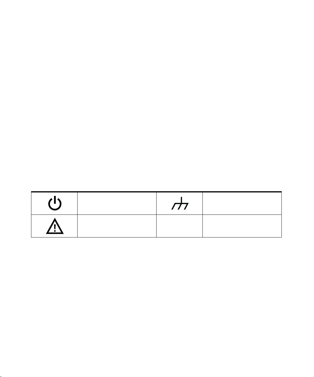
Safety Symbols
The following symbols on the instrument and in the documentation indicate
precautions which must be taken to maintain safe operation of the instrument.
Standby Power. Unit is not completely
disconnected from AC mains when
power switch is in standby position.
Frame or chassis (ground) terminal
Caution, risk of danger (refer to this
manual for specific Warning or Caution
information)
Keysight 53210A/53220A/53230A Assembly Level Service Guide 5
CAT I
IEC Measurement Category I. Do NOT
connect inputs to AC mains or to
circuits derived from AC mains.
Page 6

Safety Information
The following general safety precautions must be observed during all phases of
operation of this instrument. Failure to comply with these precautions or with
specific warnings or operating instructions in the product manuals violates safety
standards of design, manufacture, and intended use of the instrument. Keysight
Technologies assumes no liability for the customer's failure to comply with these
requirements.
General
Do not use this product in any manner not specified by the manufacturer. The
protective features of this product may be impaired if it is used in a manner not
specified in the operation instructions.
Before applying power
Verify that all safety precautions are taken. Note the instrument's external
markings described under "Safety Symbols".
Ground the instrument
The Keysight 53210A/53220A/53230A is provided with a grounding-type power
plug. The instrument chassis and cover must be connected to an electrical ground
to minimize shock hazard. The ground pin must be firmly connected to an
electrical ground (safety ground) terminal at the power outlet. Any interruption of
the protective (grounding) conductor or disconnection of the protective earth
terminal will cause a potential shock hazard that could result in personal injury.
Fuses
The Keysight 53210A/53220A/53230A is provided with an internal line fuse
appropriate for the line voltages listed on the instrument. This fuse is not user
accessible.
6 Keysight 53210A/53220A/53230A Assembly Level Service Guide
Page 7

Do not operate in an explosive atmosphere
Do not operate the instrument in the presence of flammable gases or fumes.
Do not operate near flammable liquids
Do not operate the instrument in the presence of flammable liquids or near
containers of such liquids.
Do not remove the instrument cover
Only qualified, service-trained personnel who are aware of the hazards involved
should remove instrument covers. Always disconnect the power cable and any
external circuits before removing the instrument cover.
Do not modify the instrument
Do not install substitute parts or perform any unauthorized modification to the
product. Return the product to a Keysight Sales and Service Office for service and
repair to ensure that safety features are maintained.
In case of damage
Instruments that appear damaged or defective should be made inoperative and
secured against unintended operation until they can be repaired by qualified
service personnel.
Cleaning the instrument
Clean the outside of the instrument with a soft, lint-free, slightly-dampened cloth.
Do not use detergents or chemical solvents.
Keysight 53210A/53220A/53230A Assembly Level Service Guide 7
Page 8
WARNING
Do not connect the input channels of the 53210A/53220A/53230A to AC
line-voltage mains or to circuits derived from AC mains. The instrument
must be used in CAT I (isolated from mains) applications only. Do not use in
other IEC Measurement Category (CAT II, CAT III, or CAT IV) applications.
Failure to observe these precautions may result in electric shock and serious
personal injury.
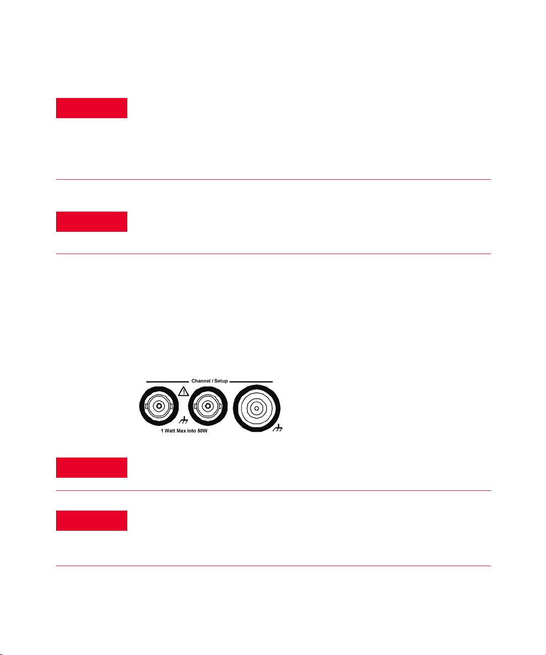
WARNING
Protection limits
WARNING
The BNC shells of the input terminals are connected to the instrument
chassis. Verify signal polarity before making any connections to the input
terminals.
The Keysight 53210A/53220A/53230A 350 MHz Universal Frequency Counter/
Timer provides protection circuitry to prevent damage to the instrument and to
protect against the danger of electric shock, provided the Protection Limits are
not exceeded and the instrument is properly grounded. To ensure safe operation
of the instrument, do not exceed the Protection Limits defined on the front panel:
During battery operation, the maximum measured signal supplied by the
user is +42 V.
WARNING
8 Keysight 53210A/53220A/53230A Assembly Level Service Guide
Product Options 201/202 add parallel Channel 1 and Channel 2 inputs to the
rear panel of the instrument. Signals on the center conductor of either
panel’s channel BNCs are also present on the corresponding center
conductor of the BNC on the opposite panel.
Page 9

Installing the instrument
The Keysight 53210A/53220A/53230A operates in the following line-voltage
ranges:
100 V to 240 V, 50 Hz to 60 Hz
100 V to 127 V, 440 Hz
90 VA Max
Instrument ventilation is through the sides and rear. Do not obstruct the
ventilation holes in any of these locations.
Battery operation
When operating the 53210A or 53220A under battery power (Option 300), failure
to observe the following warnings may result in damage to the instrument,
electric shock, and serious personal injury:
WARNING
WARNING
Keysight 53210A/53220A/53230A Assembly Level Service Guide 9
Connect the instrument chassis to earth ground during battery operation to
minimize shock hazard. Any interruption or disconnection of the protective
earth terminal will cause a potential shock hazard that could result in
personal injury.
Under battery power, the instrument chassis may float to the potential of the
measured signal supplied by the user.
Page 10

Waste Electrical and Electronic Equipment (WEEE) Directive
This instrument complies with the WEEE Directive marking requirement. This
affixed product label indicates that you must not discard this electrical or
electronic product in domestic household waste.
Product category:
With reference to the equipment types in the WEEE directive Annex 1, this
instrument is classified as a “Monitoring and Control Instrument” product.
The affixed product label is as shown below.
Do not dispose in domestic household waste.
To return this unwanted instrument, contact your nearest Keysight Service Center,
or visit http://about.keysight.com/en/companyinfo/environment/takeback.shtml
for more information.
Sales and Technical Support
To contact Keysight for sales and technical support, refer to the support links on
the following Keysight websites:
– www.keysight.com/find/53210A
www.keysight.com/find/53220A
www.keysight.com/find/53220A
(product-specific information and support, software and
documentation updates)
– www.keysight.com/find/assist
(worldwide contact information for repair and service)
10 Keysight 53210A/53220A/53230A Assembly Level Service Guide
Page 11

Table of Contents
Software Updates/Licenses . . . . . . . . . . . . . . . . . . . . . . . . . . . . . . . . . . .3
Assistance . . . . . . . . . . . . . . . . . . . . . . . . . . . . . . . . . . . . . . . . . . . . . . . . .4
Certification . . . . . . . . . . . . . . . . . . . . . . . . . . . . . . . . . . . . . . . . . . . . . . . .4
Exclusive Remedies . . . . . . . . . . . . . . . . . . . . . . . . . . . . . . . . . . . . . . . . . .4
Lithium Battery Recycling . . . . . . . . . . . . . . . . . . . . . . . . . . . . . . . . . . . . .5
Safety Symbols . . . . . . . . . . . . . . . . . . . . . . . . . . . . . . . . . . . . . . . . . . . . .5
Safety Information . . . . . . . . . . . . . . . . . . . . . . . . . . . . . . . . . . . . . . . . . .6
General . . . . . . . . . . . . . . . . . . . . . . . . . . . . . . . . . . . . . . . . . . . . . . . . .6
Before applying power . . . . . . . . . . . . . . . . . . . . . . . . . . . . . . . . . . . . .6
Ground the instrument . . . . . . . . . . . . . . . . . . . . . . . . . . . . . . . . . . . .6
Fuses . . . . . . . . . . . . . . . . . . . . . . . . . . . . . . . . . . . . . . . . . . . . . . . . . .6
Do not operate in an explosive atmosphere . . . . . . . . . . . . . . . . . . . .7
Do not operate near flammable liquids . . . . . . . . . . . . . . . . . . . . . . . .7
Do not remove the instrument cover . . . . . . . . . . . . . . . . . . . . . . . . .7
Do not modify the instrument . . . . . . . . . . . . . . . . . . . . . . . . . . . . . . .7
In case of damage . . . . . . . . . . . . . . . . . . . . . . . . . . . . . . . . . . . . . . . .7
Cleaning the instrument . . . . . . . . . . . . . . . . . . . . . . . . . . . . . . . . . . .7
Protection limits . . . . . . . . . . . . . . . . . . . . . . . . . . . . . . . . . . . . . . . . . .8
Installing the instrument . . . . . . . . . . . . . . . . . . . . . . . . . . . . . . . . . . .9
Battery operation . . . . . . . . . . . . . . . . . . . . . . . . . . . . . . . . . . . . . . . . .9
Waste Electrical and Electronic Equipment (WEEE) Directive . . . . . . .10
Product category: . . . . . . . . . . . . . . . . . . . . . . . . . . . . . . . . . . . . . . .10
Sales and Technical Support . . . . . . . . . . . . . . . . . . . . . . . . . . . . . . . . .10
1 Performance Tests
Introduction . . . . . . . . . . . . . . . . . . . . . . . . . . . . . . . . . . . . . . . . . . . . . .24
Chapter overview . . . . . . . . . . . . . . . . . . . . . . . . . . . . . . . . . . . . . . . .25
Recommended calibration cycle . . . . . . . . . . . . . . . . . . . . . . . . . . . .27
Internal auto-calibration . . . . . . . . . . . . . . . . . . . . . . . . . . . . . . . . . .27
Equipment required . . . . . . . . . . . . . . . . . . . . . . . . . . . . . . . . . . . . . .28
Power-On Test . . . . . . . . . . . . . . . . . . . . . . . . . . . . . . . . . . . . . . . . . . . .29
Keysight 53210A/53220A/53230A Assembly Level Service Guide 11
Page 12

Self-Test (Q) . . . . . . . . . . . . . . . . . . . . . . . . . . . . . . . . . . . . . . . . . . . . . .31
Run internal self-test . . . . . . . . . . . . . . . . . . . . . . . . . . . . . . . . . . . . . 31
Keysight 53210A/53220A/53230A Operational Verification . . . . . . . . . 33
Frequency checks . . . . . . . . . . . . . . . . . . . . . . . . . . . . . . . . . . . . . . . 33
Termination checks (optional) . . . . . . . . . . . . . . . . . . . . . . . . . . . . . . 35
Keysight 53210A/53220A/53230A Complete Performance Tests . . . . 37
Test 1: (Q) Absolute time base . . . . . . . . . . . . . . . . . . . . . . . . . . . . . 38
Test 2: (Q) Frequency accuracy - channels 1 and 2 . . . . . . . . . . . . . 44
Test 3: Single period . . . . . . . . . . . . . . . . . . . . . . . . . . . . . . . . . . . . . 50
Test 4: (Q) Pulse width . . . . . . . . . . . . . . . . . . . . . . . . . . . . . . . . . . .56
Test 5: (Q) Time interval . . . . . . . . . . . . . . . . . . . . . . . . . . . . . . . . . . 61
Test 6a: (Q) Frequency accuracy - channel 2/3, option 106
(6 GHz microwave channel) . . . . . . . . . . . . . . . . . . . . . . . . . . . . .66
Test 6b: (Q) Frequency accuracy - channel 2/3, option 115
(15 GHz microwave channel) . . . . . . . . . . . . . . . . . . . . . . . . . . . . 72
Test 7a: (Q) Pulse burst frequency - 53230A channel 3 option 150 with
option 106 . . . . . . . . . . . . . . . . . . . . . . . . . . . . . . . . . . . . . . . . . . . 78
Test 7c: (Q) Pulse burst frequency - 53230A channel 3 option 150 with
option 115 . . . . . . . . . . . . . . . . . . . . . . . . . . . . . . . . . . . . . . . . . . . 84
Keysight 53210A/53220A/53230A Operational Verification and Perfor-
mance Test Record . . . . . . . . . . . . . . . . . . . . . . . . . . . . . . . . . . . . . . 90
Keysight 53210A/53220A/53230A Performance Test Record
(Tests 1 to 7) . . . . . . . . . . . . . . . . . . . . . . . . . . . . . . . . . . . . . . . . . . . 91
2 Service
Introduction . . . . . . . . . . . . . . . . . . . . . . . . . . . . . . . . . . . . . . . . . . . . .102
Returning the counter to Keysight Technologies for service . . . . .102
About the Keysight 53210A/53220A/53230A calibration menu . . 102
The Keysight 53210A/53220A/53230A calibration procedures . . . 102
Pre-troubleshooting information . . . . . . . . . . . . . . . . . . . . . . . . . .102
Troubleshooting information . . . . . . . . . . . . . . . . . . . . . . . . . . . . . . 102
Returning the Instrument to Keysight Technologies for Service . . . .106
Operating checklist . . . . . . . . . . . . . . . . . . . . . . . . . . . . . . . . . . . . . 106
Is the instrument inoperative? . . . . . . . . . . . . . . . . . . . . . . . . . . . . . 106
12 Keysight 53210A/53220A/53230A Assembly Level Service Guide
Page 13

Does the instrument fail self-test? . . . . . . . . . . . . . . . . . . . . . . . . .106
Types of service available . . . . . . . . . . . . . . . . . . . . . . . . . . . . . . . .106
Extended service contracts . . . . . . . . . . . . . . . . . . . . . . . . . . . . . . .106
Obtaining repair service (worldwide) . . . . . . . . . . . . . . . . . . . . . . . .107
To provide repair information . . . . . . . . . . . . . . . . . . . . . . . . . . . . .108
To pack in the original packaging materials . . . . . . . . . . . . . . . . . .109
To pack in commercially available materials . . . . . . . . . . . . . . . . . .109
Warranty . . . . . . . . . . . . . . . . . . . . . . . . . . . . . . . . . . . . . . . . . . . . .110
About the Keysight 53210A/53220A/53230A Calibration Menu . . . .111
Overview of the Keysight 53210A/53220A/53230A calibration menu .
111
To get help with the calibration menu functions . . . . . . . . . . . . . .113
To view the calibration menu and security status from the counter front
panel . . . . . . . . . . . . . . . . . . . . . . . . . . . . . . . . . . . . . . . . . . . . . .115
To lock the counter against calibration . . . . . . . . . . . . . . . . . . . . . .116
To unlock the counter for calibration: . . . . . . . . . . . . . . . . . . . . . . .118
To change to a new security code . . . . . . . . . . . . . . . . . . . . . . . . . .119
The Keysight 53210A/53220A/53230A Calibration Procedures . . . . .120
Equipment required . . . . . . . . . . . . . . . . . . . . . . . . . . . . . . . . . . . . .120
Determine the counter firmware version . . . . . . . . . . . . . . . . . . . . .121
Calibration cycle . . . . . . . . . . . . . . . . . . . . . . . . . . . . . . . . . . . . . . .123
Calibration string: . . . . . . . . . . . . . . . . . . . . . . . . . . . . . . . . . . . . . .123
Internal reference oscillator calibration . . . . . . . . . . . . . . . . . . . . .123
Summary of oscillator calibration procedure: . . . . . . . . . . . . . . . . .128
Remote oscillator calibration summary: . . . . . . . . . . . . . . . . . . . . .128
Voltage calibration (internal DACs) . . . . . . . . . . . . . . . . . . . . . . . . .129
Option 106 microwave channel frequency calibration . . . . . . . . . .135
Option 115 microwave channel frequency calibration . . . . . . . . . .142
Internal auto-calibration . . . . . . . . . . . . . . . . . . . . . . . . . . . . . . . . .149
To view the calibration count . . . . . . . . . . . . . . . . . . . . . . . . . . . . .152
Resetting the security code to a null . . . . . . . . . . . . . . . . . . . . . . . .153
Pre-Troubleshooting Information . . . . . . . . . . . . . . . . . . . . . . . . . . . . .154
Safety considerations . . . . . . . . . . . . . . . . . . . . . . . . . . . . . . . . . . .154
Recommended test equipment . . . . . . . . . . . . . . . . . . . . . . . . . . . .155
Repair considerations . . . . . . . . . . . . . . . . . . . . . . . . . . . . . . . . . . .156
Keysight 53210A/53220A/53230A Assembly Level Service Guide 13
Page 14

After service considerations . . . . . . . . . . . . . . . . . . . . . . . . . . . . . . 157
Troubleshooting the Counter . . . . . . . . . . . . . . . . . . . . . . . . . . . . . . . . 162
Unit is inoperative . . . . . . . . . . . . . . . . . . . . . . . . . . . . . . . . . . . . . . 162
Unit fails self-test . . . . . . . . . . . . . . . . . . . . . . . . . . . . . . . . . . . . . . 162
Power supply check . . . . . . . . . . . . . . . . . . . . . . . . . . . . . . . . . . . . . 162
Checking the battery and battery charger . . . . . . . . . . . . . . . . . . . 166
Performing the counter self-test . . . . . . . . . . . . . . . . . . . . . . . . . . . 171
To determine the counter firmware version . . . . . . . . . . . . . . . . . . 172
Reseat the boards . . . . . . . . . . . . . . . . . . . . . . . . . . . . . . . . . . . . . .174
Re-run the counter self test . . . . . . . . . . . . . . . . . . . . . . . . . . . . . . 175
Error Messages . . . . . . . . . . . . . . . . . . . . . . . . . . . . . . . . . . . . . . . . . . . 176
Command errors (-100...) . . . . . . . . . . . . . . . . . . . . . . . . . . . . . . . . 176
Execution errors (-200...) . . . . . . . . . . . . . . . . . . . . . . . . . . . . . . . . 176
Hardware errors (-240, -241, -250...) . . . . . . . . . . . . . . . . . . . . . . . 177
Device-specific errors (-300..., +800) . . . . . . . . . . . . . . . . . . . . . . . 178
Query errors (-400...) . . . . . . . . . . . . . . . . . . . . . . . . . . . . . . . . . . . . 179
Calibration errors (700...) . . . . . . . . . . . . . . . . . . . . . . . . . . . . . . . . 179
Self-test errors (901...) . . . . . . . . . . . . . . . . . . . . . . . . . . . . . . . . . .180
3 Replacing Assemblies
Introduction . . . . . . . . . . . . . . . . . . . . . . . . . . . . . . . . . . . . . . . . . . . . .184
Tools Required . . . . . . . . . . . . . . . . . . . . . . . . . . . . . . . . . . . . . . . . . . . 185
Do this first . . . . . . . . . . . . . . . . . . . . . . . . . . . . . . . . . . . . . . . . . . .185
Electrostatic discharge . . . . . . . . . . . . . . . . . . . . . . . . . . . . . . . . . . 186
To Remove the Cover and Rear Bezel . . . . . . . . . . . . . . . . . . . . . . . . .187
To Remove the Internal DC Battery Assembly (Option 300) . . . . . . . . 189
To Remove the GPIB Assembly . . . . . . . . . . . . . . . . . . . . . . . . . . . . . . 191
To Remove a 6.0 GHz or 15.0 GHz Microwave Channel Assembly (Options
106/115) . . . . . . . . . . . . . . . . . . . . . . . . . . . . . . . . . . . . . . . . . . . . . 192
Re-installing the microwave channel assembly . . . . . . . . . . . . . . . 192
To Remove the Processor Board . . . . . . . . . . . . . . . . . . . . . . . . . . . . . 195
To Remove the Front Panel Assembly . . . . . . . . . . . . . . . . . . . . . . . . .196
To remove the display assembly from the front panel . . . . . . . . . . 199
14 Keysight 53210A/53220A/53230A Assembly Level Service Guide
Page 15

To Remove the Motherboard . . . . . . . . . . . . . . . . . . . . . . . . . . . . . . . .200
To Remove the AC Power Supply Assembly . . . . . . . . . . . . . . . . . . . .201
4 Retrofitting Options
Introduction . . . . . . . . . . . . . . . . . . . . . . . . . . . . . . . . . . . . . . . . . . . . .204
Tools required . . . . . . . . . . . . . . . . . . . . . . . . . . . . . . . . . . . . . . . . .204
Do This first . . . . . . . . . . . . . . . . . . . . . . . . . . . . . . . . . . . . . . . . . . .205
To Retrofit Ultra-High Stability Timebase (Option 010) . . . . . . . . . . .206
To Retrofit the GPIB Connector . . . . . . . . . . . . . . . . . . . . . . . . . . . . . .207
GPIB connector parts (P/N 53200U-400) . . . . . . . . . . . . . . . . . . . .207
Preliminary steps . . . . . . . . . . . . . . . . . . . . . . . . . . . . . . . . . . . . . . .207
GPIB connector installation procedure . . . . . . . . . . . . . . . . . . . . . .208
To Retrofit the Internal Battery DC Power (Option 300) . . . . . . . . . . .209
Option 300 DC power input assembly parts . . . . . . . . . . . . . . . . . .209
Preliminary steps . . . . . . . . . . . . . . . . . . . . . . . . . . . . . . . . . . . . . . .209
Battery assembly installation procedure . . . . . . . . . . . . . . . . . . . . .210
To Retrofit the 53210A (Channel 1) or 53220A/53230A
(Channels 1/2) Rear Panel Inputs (Option 201) . . . . . . . . . . . . . . .215
Option 201 rear panel channel 1/2 parts . . . . . . . . . . . . . . . . . . . .215
Preliminary steps . . . . . . . . . . . . . . . . . . . . . . . . . . . . . . . . . . . . . . .215
Channels 1/2 rear panel retrofit procedure . . . . . . . . . . . . . . . . . .217
To Retrofit the 53210A Channel 2 Front Panel Input
(Option 106 or Option 115, plus Front Panel Option 202) . . . . . . .219
Option 106/115 channel 2 parts . . . . . . . . . . . . . . . . . . . . . . . . . . .219
Option 202 front panel channel 2 parts . . . . . . . . . . . . . . . . . . . . .219
Preliminary steps . . . . . . . . . . . . . . . . . . . . . . . . . . . . . . . . . . . . . . .220
Channel 2 front panel retrofit procedure (53210A) . . . . . . . . . . . .222
To Retrofit the 53210A Channel 2 Rear Panel Input, 6.0 GHz (Option 106)
or 15.0 GHz (Option 115) plus Rear Panel Option 203 . . . . . . . . . .229
Option 106/115 channel 2 parts . . . . . . . . . . . . . . . . . . . . . . . . . . .229
Option 203 rear panel channel 2 parts . . . . . . . . . . . . . . . . . . . . . .229
Preliminary steps . . . . . . . . . . . . . . . . . . . . . . . . . . . . . . . . . . . . . . .230
Channel 2 rear panel retrofit procedure (53210A) . . . . . . . . . . . . .232
Keysight 53210A/53220A/53230A Assembly Level Service Guide 15
Page 16

To Retrofit the 53220A/53230A Channel 3 Input, 6.0 GHz
(Option 106) or 15.0 GHz (Option 115) plus Front panel option 202 .
234
Option 202 front panel channel 3 parts . . . . . . . . . . . . . . . . . . . . . 234
Preliminary steps . . . . . . . . . . . . . . . . . . . . . . . . . . . . . . . . . . . . . . .235
Front panel installation procedure (Option 202 only) . . . . . . . . . .237
To Retrofit the 53220A/53230A Channel 3 Input, 6.0 GHz
(Option 106) or 15.0 GHz (Option 115) plus Rear Panel Option 203 . .
244
Option 203 rear panel channel 3 parts . . . . . . . . . . . . . . . . . . . . . .244
Preliminary steps . . . . . . . . . . . . . . . . . . . . . . . . . . . . . . . . . . . . . . .245
Rear panel installation procedure (Option 203 only) . . . . . . . . . . . 247
To Retrofit Option 150 (Pulse Microwave Measurements) for the 53230A
249
Retrofitting procedure . . . . . . . . . . . . . . . . . . . . . . . . . . . . . . . . . . . 249
5 Replaceable Parts
Introduction . . . . . . . . . . . . . . . . . . . . . . . . . . . . . . . . . . . . . . . . . . . . .252
Contacting Keysight Technologies . . . . . . . . . . . . . . . . . . . . . . . . . . .253
By telephone (in the United States): . . . . . . . . . . . . . . . . . . . . . . . . 253
For mail correspondence, use the address below: . . . . . . . . . . . . . 253
How To Order A Part . . . . . . . . . . . . . . . . . . . . . . . . . . . . . . . . . . . . . . 254
Parts Identification . . . . . . . . . . . . . . . . . . . . . . . . . . . . . . . . . . . . .254
Replaceable Parts . . . . . . . . . . . . . . . . . . . . . . . . . . . . . . . . . . . . . . . .256
6 Backdating
Introduction . . . . . . . . . . . . . . . . . . . . . . . . . . . . . . . . . . . . . . . . . . . . .262
Serial numbers . . . . . . . . . . . . . . . . . . . . . . . . . . . . . . . . . . . . . . . . 262
Backdating Firmware . . . . . . . . . . . . . . . . . . . . . . . . . . . . . . . . . . . . . .264
To determine the counter firmware version . . . . . . . . . . . . . . . . . . 264
Procedure Changes . . . . . . . . . . . . . . . . . . . . . . . . . . . . . . . . . . . . . . . 266
Information concerning Option 106 “Microwave Input”, FW Rev (27.0)
266
16 Keysight 53210A/53220A/53230A Assembly Level Service Guide
Page 17

Option 106 microwave channel frequency calibration . . . . . . . . . .266
Backdating Hardware . . . . . . . . . . . . . . . . . . . . . . . . . . . . . . . . . . . . . .273
Backdating Specifications . . . . . . . . . . . . . . . . . . . . . . . . . . . . . . . . . .274
Keysight 53210A/53220A/53230A Assembly Level Service Guide 17
Page 18

THIS PAGE HAS BEEN INTENTIONALLY LEFT BLANK.
18 Keysight 53210A/53220A/53230A Assembly Level Service Guide
Page 19

List of Figures
Figure 1-1 Operational verification setup for Keysight 53210A/220A/
Figure 1-2 Termination Check Setup . . . . . . . . . . . . . . . . . . . . . . .35
Figure 1-3 Absolute timebase test setup . . . . . . . . . . . . . . . . . . .39
Figure 1-4 Test setup for channel 1/2 frequency accuracy tests .44
Figure 1-5 Test Setup for Single Period . . . . . . . . . . . . . . . . . . . .51
Figure 1-6 Pulse width test setup . . . . . . . . . . . . . . . . . . . . . . . . .57
Figure 1-7 Time interval (channel 1 to 2) test setup . . . . . . . . . . .62
Figure 1-8 Option 106 ( 6 GHz ) microwave channel 2/3 test setup
Figure 1-9 Option 115 ( 15 GHz ) microwave channel 2/3 test setup
Figure 1-10 Option 106/150 microwave channel 3 test setup . . . .79
Figure 1-11 Option 115/150 microwave channel 3 test setup . . . .85
Figure 2-1 The front panel at a glance . . . . . . . . . . . . . . . . . . . .103
Figure 2-2 Front panel display . . . . . . . . . . . . . . . . . . . . . . . . . . .104
Figure 2-3 Calibration procedure summary . . . . . . . . . . . . . . . .114
Figure 2-4 Information screen . . . . . . . . . . . . . . . . . . . . . . . . . . .122
Figure 2-5 Oscillator calibration setup . . . . . . . . . . . . . . . . . . . .124
Figure 2-6 DC voltage source and DMM connections . . . . . . . .132
Figure 2-7 Microwave source connection to Channel 3 . . . . . . .135
Figure 2-8 Microwave source connection to Channel 3 . . . . . . .143
Figure 2-9 Counter top internal view . . . . . . . . . . . . . . . . . . . . . .160
Figure 2-10 Bottom internal view . . . . . . . . . . . . . . . . . . . . . . . . .161
Figure 2-11 ac Power Supply Testpoint Locations on the Motherboard
Figure 2-12 Battery folded in the service position . . . . . . . . . . . .167
Figure 2-13 Test Button and Charge Indicator . . . . . . . . . . . . . . .168
Figure 3-1 Handle removal . . . . . . . . . . . . . . . . . . . . . . . . . . . . .187
Figure 3-2 Rear Bezel And Cover Removal . . . . . . . . . . . . . . . . .188
Figure 3-3 Battery assembly temporary position for service or
Figure 3-4 Top view of counter showing GPIB assembly . . . . . .191
230A . . . . . . . . . . . . . . . . . . . . . . . . . . . . . . . . . . . . .33
67
73
assembly (top view, internal battery removed, test
points visible.) . . . . . . . . . . . . . . . . . . . . . . . . . . . .164
Removal . . . . . . . . . . . . . . . . . . . . . . . . . . . . . . . . .190
Keysight 53210A/53220A/53230A Assembly Level Service Guide 19
Page 20

Figure 3-5 Front flange resting on plastic tab . . . . . . . . . . . . . . 193
Figure 3-6 Processor PC board . . . . . . . . . . . . . . . . . . . . . . . . . . 195
Figure 3-7 Front rubber bumper removal . . . . . . . . . . . . . . . . . . 196
Figure 3-8 Front panel removal . . . . . . . . . . . . . . . . . . . . . . . . . . 197
Figure 4-1 Connector Locking Tab . . . . . . . . . . . . . . . . . . . . . . . 210
Figure 4-2 Jumper cable installed . . . . . . . . . . . . . . . . . . . . . . .211
Figure 4-3 Digital and Y-cables. . . . . . . . . . . . . . . . . . . . . . . . . . 212
Figure 4-4 Test button and charge indicator . . . . . . . . . . . . . . .212
Figure 4-5 Battery assembly connectors . . . . . . . . . . . . . . . . . . 213
Figure 4-6 Battery assembly held by three small tabs . . . . . . . . 214
Figure 4-7 Option 201 rear input channels 1 and 2 . . . . . . . . . . 217
Figure 4-8 53210A channel 2 front panel Option 106/202 . . . . 221
Figure 4-9 Processor printed circuit board . . . . . . . . . . . . . . . . .222
Figure 4-10 T20 TORX screw on motherboard . . . . . . . . . . . . . . . 223
Figure 4-11 Connector-adapter installation . . . . . . . . . . . . . . . . . 224
Figure 4-12 Semi-rigid cable position . . . . . . . . . . . . . . . . . . . . . . 225
Figure 4-13 Front flange resting on plastic tab . . . . . . . . . . . . . . 227
Figure 4-14 53210A channel 2 rear panel Option 106/203 . . . . . 231
Figure 4-15 Channel 2 assembly installed on top of the motherboard,
with the SMA edge connector pointing toward the rear
of the counter. . . . . . . . . . . . . . . . . . . . . . . . . . . . . 232
Figure 4-16 53220A/53230A Option 106/202. . . . . . . . . . . . . . . .236
Figure 4-17 Processor printed circuit board. . . . . . . . . . . . . . . . .237
Figure 4-18 T20 TORX screw on motherboard . . . . . . . . . . . . . . . 238
Figure 4-19 Connector-adapter parts . . . . . . . . . . . . . . . . . . . . . . 240
Figure 4-20 Semi-rigid cable position . . . . . . . . . . . . . . . . . . . . . . 241
Figure 4-21 53220A/53230A rear panel option 106/203. . . . . . . 246
Figure 4-22 Channel 3 assembly installed on top of the motherboard,
with the female SMA edge connector pointing toward
the rear. . . . . . . . . . . . . . . . . . . . . . . . . . . . . . . . . . 247
Figure 5-1 Keysight 53210A/53220A/53230A Counters, top view
(cover off) . . . . . . . . . . . . . . . . . . . . . . . . . . . . . . .259
Figure 5-2 Keysight 53210A/53220A/53230A Counters, bottom view
(cover off) . . . . . . . . . . . . . . . . . . . . . . . . . . . . . . .260
Figure 6-1 Information screen . . . . . . . . . . . . . . . . . . . . . . . . . . . 265
Figure 6-2 Microwave source connection to channel 3 . . . . . . . 267
20 Keysight 53210A/53220A/53230A Assembly Level Service Guide
Page 21

List of Tables
Table 1-1 Recommended test equipment for operational verification
and performance tests . . . . . . . . . . . . . . . . . . . . . .28
Table 1-2 The Keysight 53210A/53220A/53230A performance
tests . . . . . . . . . . . . . . . . . . . . . . . . . . . . . . . . . . . . .38
Table 2-1 Recommended test equipment for calibration . . . . .120
Table 2-2 Option 106 calibration frequencies and power levels . . .
139
Table 2-3 Option 115 calibration frequencies and power levels . . .
147
Table 2-4 Recommended equipment for test and troubleshooting
155
Table 2-5 Keysight 53210A/53220A/53230A assembly
identification . . . . . . . . . . . . . . . . . . . . . . . . . . . . .158
Table 2-6 DC power supply voltages . . . . . . . . . . . . . . . . . . . . .165
Table 5-1 Table of replaceable parts . . . . . . . . . . . . . . . . . . . . .256
Table 6-1 Instruments this guide directly applies to . . . . . . . . .262
Keysight 53210A/53220A/53230A Assembly Level Service Guide 21
Page 22

THIS PAGE HAS BEEN INTENTIONALLY LEFT BLANK.
22 Keysight 53210A/53220A/53230A Assembly Level Service Guide
Page 23

Keysight 53210A/53220A/53230A 350 MHz Universal Frequency
Counter/Timer
Assembly Level Service Guide
1 Performance Tests
Introduction 24
Power-On Test 29
Self-Test (Q) 31
Keysight 53210A/53220A/53230A Operational Verification 33
Keysight 53210A/53220A/53230A Complete Performance Tests 37
Keysight 53210A/53220A/53230A Operational Verification and Performance
Test Record 90
Keysight 53210A/53220A/53230A Performance Test Record (Tests 1 to 7)
91
Verifying specifications.
23
Page 24

1 Performance Tests
Introduction
This chapter provides procedures to test the electrical performance of
the Keysight 53210A/53220A/53230A Frequency Counters, using the
specifications provided on the CD-ROM (“Keysight 53210A/53220A/53230A
Specifications”) that came with your counter. Successful completion of all the
performance tests verifies the counter is meeting all factory specifications.
Four types of testing are provided:
– Power-on test
– Counter self-test
– operational Verification Tests
– Complete performance tests
This chapter is organized as follows:
– Introduction
– Power-On Test
– Self-Test (Q)
– Keysight 53210A/53220A/53230A Operational Verification
– Keysight 53210A/53220A/53230A Complete Performance Tests
– Keysight 53210A/53220A/53230A Operational Verification and Performance
Test Record
– Keysight 53210A/53220A/53230A Performance Test Record (Tests 1 to 7)
24 Keysight 53210A/53220A/53230A Assembly Level Service Guide
Page 25

Chapter overview
Power-on test
When the counter is first turned ON, a limited turn-on test is performed to verify
the counter is sufficiently functional to perform basic operations.
Self-test
Running the counter Self-Test initiates a series of checks against internal
standards. Successful completion of the Self-Test provides a high confidence level
that the counter is completely functional. No external test equipment is required
for this operator-initiated test.
Operational verification
The operational verification is an abbreviated check that may be performed to give
a strong degree of confidence that the instrument is capable of making basic
measurements accurately without running the complete performance tests. An
operational verification is useful for incoming inspection and routine preventative
maintenance.
Complete performance verification tests
Performance Tests 1
The complete performance verification tests verify the specifications listed on the
Keysight 53210A/53220A/53230A Product Reference CD-ROM as “Keysight
53210A/53220A/53230A Specifications.” All tests can be performed without
accessing the inside of the instrument. The complete performance tests are
recommended as acceptance tests upon initial receipt of your counter. They will
also help you to become familiar with its performance and operation. Complete
performance tests should be run at least once a year to ensure the counter is
meeting all specifications.
Quick performance check A combination of selected performance tests
(marked ‘Q’) plus the counter Self-Test provides a simple method to achieve a
high confidence in the counter’s ability to both functionally operate and to meet
specifications. These tests represent the absolute minimum set of performance
checks recommended following any service activity.
Keysight 53210A/53220A/53230A Assembly Level Service Guide 25
Page 26

1 Performance Tests
Auditing the counter’s performance for the quick check points (designated by a
‘Q’) verifies performance for normal accuracy drift mechanisms.
This test does not check for abnormal component failures. To perform the quick
performance check, do the following:
– Perform the counter Self-Test as shown on page 31.
– Perform only the performance verification tests indicated with the letter Q at
the beginning of the test.
– If the counter fails the quick performance check, repair may be required. Refer
to “Troubleshooting the Counter” on page 162.
Remote testing of the counter
All of the counter tests may be run using an automated test system and remote
programming commands. Three interfaces are provided in each counter to allow
operation over an interface from a remote computer: GPIB, LAN, and USB. Refer
to the SCPI Programmer’s Reference for information on the remote commands
available for controlling the counter.
Performance test record
The results of the operational verification, and performance tests should be
recorded on a copy of the Performance Test Record, located at the end of the
complete performance tests section in this chapter.
Test considerations
For optimum performance, all performance tests should comply with the following
recommendations:
– Ensure that the ambient temperature for running the Performance Tests is
stable and between 18 degrees C and 28 degrees C. Ideally, the tests should
be performed at 23o C ±1o C.
– Ensure that ambient relative humidity is less than 80%.
– See page 37 for warm-up considerations.
– Keep the instrument cables as short as possible, consistent with the
impedance requirements. Use only RG-58 or equivalent 50 cable for
measurements.
26 Keysight 53210A/53220A/53230A Assembly Level Service Guide
Page 27

– To verify the total number of accuracy places for frequency measurements, it
may be necessary to turn off Auto-Digit control. Use this set of key depressions
to turn AutoDigits OFF:
[Digits] / (AutoDigits) / <Off>
– The softkey menus shown in the test procedures represent the functionality of
the 53230A. The softkey menus for the 53210A and 53220A may be different
depending on the function selected.
Recommended calibration cycle
The counter requires periodic verification of operation. Depending on the use and
environmental conditions, aging, and measurement accuracy required, the
counter should be checked using the operational verification procedure at least
once every year. The recommended calibration cycle for specification accuracy is
also one year.
Internal auto-calibration
An Internal Auto-Calibration feature is available (see Chapter 2, "Service") that
uses internal instrument standards to refine the accuracy of the counter. It is
recommended that Auto-Cal be performed regularly (such as at the beginning of a
shift change, starting a contemporary series of measurements, after a large
ambient temperature change, etc.) for optimum counter performance.
Performance Tests 1
NOTE
Keysight 53210A/53220A/53230A Assembly Level Service Guide 27
Auto-calibration is also a subset of the counter self-test.
Page 28

1 Performance Tests
Equipment required
Table 1-1 Recommended test equipment for operational verification and
Instrument Required characteristics Recommended model
performance tests
100 MHz to 15 GHz; Freq Accy at
Microwave signal generator
Pulse generator
RF signal generator
Primary frequency standard
(10 MHz house standard)
DC power supply Adjustable to 5.000V Keysight 6234A or equivalent
Digital multimeter (DMM) Microvolt accuracy Keysight 34410A or equivalent
SMA(m)-to-BNC(f) adapters (3) Keysight 1250-1200
Type N(m)-to-BNC(f) adapter Keysight 1250-0780
BNC-to-dual banana plug BNC(f) to banana plug (m)
50 coaxial cable with
BNC connectors (5)
3.5mm cables (2) DC-18 GHz,matched pair Keysight 11500E
Coaxial BNC tee connector Keysight 1250-0781
6 GHz and 15 GHz:
PW Accy: ±10%
5 nSec pulse width
40 pSec
± 2.000E-12
10 MHz
Absolute accuracy >
1 x 10⁻¹⁰
BNC(m) to BNC(m), 48 inches Keysight 10503A
±10ppb;
±
Keysight E8257D-520-UNW or
equivalent
Keysight 81134A or equivalent
Stanford Research Systems
CG635
Stanford Research Systems
FS725 Rubidium Timebase or
equivalent
Keysight E9637A or Newark
10M4161
28 Keysight 53210A/53220A/53230A Assembly Level Service Guide
Page 29

Power-On Test
1 Inspect the counter for any damage. Make sure no cables are connected to the
2 Connect the power cord to the counter, and connect the other end of the
Performance Tests 1
input channels (rear and front panels) of the counter.
power cord to the primary power source.
NOTE
It is normal for the fan in the counter to run at different speeds as necessary
(depending upon internal temperature) when the counter is in standby mode.
Power to the timebase is continuous to maintain long term measurement
reliability, and the fan helps maintain timebase temperature stability.
3 Verify the following condition for the Power LED with power off (lower L/H
corner of the front panel).
– No OCXO or OCXO in Off mode - LED is off when power is off.
– OCXO present, heated by AC power - LED is on solid when power
is off.
– OCXO present, heated by battery power - LED blinks when power
is off.
4 Press the POWER key (lower left-hand corner of the front panel) to turn on the
counter. Verify the following results:
– The front panel display turns white as all pixels are illuminated.
– The LED under the power switch is on solid.
– After several seconds, a screen is briefly displayed that shows the status
and ID of the IP Address and the GPIB address. The factory default GPIB
address is 3. (“Disabled” means the GPIB is turned Off under [Utility] / (I/O
Config).
– The counter is now ready to measure frequency of a signal applied to
CHANNEL 1 input as indicated by illumination of the Freq softkey and
Channel 1 annunciator.
NOTE
Keysight 53210A/53220A/53230A Assembly Level Service Guide 29
An auto-cal is performed at power-on. (See “To run auto calibration:” on
page 150 for more information.)
Page 30

1 Performance Tests
NOTE
NOTE
If a fail message is displayed at power-on, refer to “Troubleshooting the
Counter” on page 162 of this service guide.
5 Mark Pass or Fail in the Keysight 53210A/53220A/53230A Power-ON Test
Record, Test 1, at the end of this chapter.
The power-on hardware initialization activities check the following circuits for
operation:
– Front panel display driver
– Power manager
– Battery (if installed)
– GPIB
– Measurement board hardware
30 Keysight 53210A/53220A/53230A Assembly Level Service Guide
Page 31

Self-Test (Q)
Performance Tests 1
A brief power-on test occurs automatically whenever you turn on the counter. This
limited test assures that the counter is functional.
NOTE
NOTE
It is recommended that the counter Self-Test be performed to ensure that the
instrument is completely functional before running the Operational Verification
or Performance Tests.
SELF-TEST and the remote command *TST perform the same internal tests.
An auto-calibration is performed as a subset of the counter Self-Test.
(See “Internal auto-calibration” on page 149 for more information.)
After turn-on, or at any time a reasonable operational status needs to be verified,
the internal Self-Test can be run.
Run internal self-test
1 Disconnect any input signal(s) from the counter.
2 Press the Utility key and then the Instr Setup softkey.
Keysight 53210A/53220A/53230A Assembly Level Service Guide 31
Page 32

1 Performance Tests
The Instrument Setup menu softkeys are displayed:
3 Press the Self Test softkey. The display shows:
– “Performing Self-Test. Please wait...” (displayed for several seconds.)
– If the self-test passes, “Self-Test Passed.” is momentarily displayed.
NOTE
If “Self-Test Failed” is displayed or any other failure is indicated, refer to the
troubleshooting section in Chapter 2, "Service" on page 101.
4 Mark Pass or Fail in the “Keysight 53210A/53220A/53230A Performance Test
Record (Tests 1 to 7)” on page 91.
32 Keysight 53210A/53220A/53230A Assembly Level Service Guide
Page 33

Performance Tests 1
Keysight 53210A/53220A/53230A Operational Verification
The operational verification consists of checks that may be performed at any time
to give a high degree of confidence that the instrument is operating properly,
without running the complete performance tests.
These checks represent the minimum set of tests recommended following any
option retrofit installations (Refer to Chapter 4, "Retrofitting Options").
If you are unfamiliar with the operation of the counter, you can review the
“Keysight 53210A/53220A/53230A Quick Start Tutorial.” However, the
procedures in this chapter are written so that little operational experience is
necessary. The procedures should be followed in the order in which they appear.
Frequency checks
1 Connect the counter’s rear-panel Int Ref Out as shown in
Figure 1-1 to the front panel Channel 1 input connector.
Int Ref
Out
Ch 1
Figure 1-1 Operational verification setup for Keysight 53210A/220A/230A
NOTE
Keysight 53210A/53220A/53230A Assembly Level Service Guide 33
If the counter has Option 201 (rear panel input connectors) installed, connect
the Int Ref Out to the rear panel Channel 1 input connector and NOT the front
panel Channel 1 input connector.
Page 34

1 Performance Tests
2 Press the Preset key to preset the counter.
3 Verify the display shows a frequency reading of approximately 10,000,000 Hz.
4 Mark Pass or Fail in the “Keysight 53210A/53220A/53230A Performance Test
Record (Tests 1 to 7)” on page 91.
NOTE
NOTE
The remaining steps apply only to the Keysight 53220A and Keysight
53230A53230A since the Keysight 53210A does not have a second RF frequency
input.
5 In the same way as for Channel 1, connect the Int Ref Out to the Channel 2 input
connector (front or rear panel).
6 Press the Channel 2 button.
If necessary, press the Freq/Period key to read the Channel 2 frequency.
– Channel 1 annunciator is not lit. Channel 2 annunciator is lit.
7 Verify the display shows a frequency reading of approximately 10,000,000 Hz.
8 Mark Pass or Fail in the “Keysight 53210A/53220A/53230A Performance Test
Record (Tests 1 to 7)” on page 91.
9 Disconnect the test setup.
34 Keysight 53210A/53220A/53230A Assembly Level Service Guide
Page 35

Termination checks (optional)
Performance Tests 1
NOTE
Once the termination checks have been successfully performed, it is usually not
necessary to run them again unless the counter’s motherboard has been
replaced.
1 Press the Preset key to preset the counter.
2 Connect a digital multimeter (DMM) to CHANNEL 1 as shown in Figure 1-2, and
set it to measure ohms (set DMM to appropriate Ohms range). On the DMM,
use a dual-banana plug-to-BNC connector.
DMM
HI
LO
Ch 1
Figure 1-2 Termination Check Setup
3 Press the Channel 1 key.
– The LED turns on and the Channel 1 Setup softkeys are displayed:
Keysight 53210A/53220A/53230A Assembly Level Service Guide 35
Page 36

1 Performance Tests
4 Select the following:
– Coupling: DC
– The DC annunciator indicates DC input coupling for Channel 1.
– Impedance: 50 Ω
– The 50 Ω annunciator turns on, indicating a 50 Ω input impedance for
5 Verify the DMM reads approximately 50 Ohms.
6 Mark Pass or Fail in the “Keysight 53210A/53220A/53230A Performance Test
Record (Tests 1 to 7)” on page 91.
7 Select the following:
– Impedance: 1 MΩ.
– The 1 MΩ annunciator turns on, indicating a 1 MΩ input impedance for
Channel 1.
8 Verify the DMM reads approximately 1.000 MOhm.
9 Mark Pass or Fail in the “Keysight 53210A/53220A/53230A Performance Test
Record (Tests 1 to 7)” on page 91.
10 Repeat steps 2 through 9 for RF Channel 2 for the Keysight 53220A/53230A
counters ONLY, since the Keysight 53210A counter does not have a standard
RF Channel 2.
11 Mark Pass or Fail in the Keysight 53220A/53230A Operational Verification Test
Record, Tests 6a and 6b for Chan 2, starting on page 91.
12 Disconnect the test setup.
Channel 1.
NOTE
36 Keysight 53210A/53220A/53230A Assembly Level Service Guide
This completes the operational verification testing for the Keysight 53210A/
53220A/53230A.
Page 37

Performance Tests 1
Keysight 53210A/53220A/53230A Complete Performance Tests
The following seven performance tests, when successful, verify that the counter
meets the instrument specifications as provided on the CD ROM that came with
your Keysight 53210A/53220A/53230A Counter. See also the information on
running a ‘QUICK’ performance test on page 25. Before running these tests,
review the “Test considerations” on page 26.
Record the results of the performance tests in the appropriate place on the
“Keysight 53210A/53220A/53230A Performance Test Record (Tests 1 to 7)” on
page 91.
To verify the total number of accuracy places for frequency measurements, it may
be necessary to turn off Auto-Digit control. Use this set of key depressions to turn
AutoDigits OFF:
[Digits] / (AutoDigits) / <Off>
NOTE
If the instrument is currently located in the calibration environment with the
power removed, turn on the instrument and allow a 45 minute warm-up period
before starting the Performance Test procedures. Upon receipt and delivery to
the calibration environment, turn on the instrument and allow a 2½ hour
warm-up/stabilization period before starting the procedures.
If it is known that the instrument has been in storage or decommissioned
(unused) for several months, turn on the instrument and allow it to stabilize for
72 hours. Periodically monitor the aging (drift) rate relative to the counter’s
24-hour specification. If the aging rate exceeds the 24-hour specification, allow
an additional stabilization period and continue to monitor the rate relative to the
specification. The counter has stabilized when aging remains within the 24-hour
rate. Otherwise, the 45 minute or 2½ warm-up period applies.
An instrument that has not or will not be used for several months should be
stored in the same ambient environment and orientation in which it will
eventually be used.
Keysight 53210A/53220A/53230A Assembly Level Service Guide 37
Page 38

1 Performance Tests
Table 1-2 The Keysight 53210A/53220A/53230A performance tests
[a]
Test description
Test 1: Absolute time base
Test 2: Frequency accuracy - channels 1 and 2
Test 3: Single period
Test 4: Pulse width
Test 5: Time interval
Test 6: Frequency accuracy - microwave channel options 106 and 115
Test 7: Pulse burst frequency - 53230A channel 3 option 150
[a] Other counter measurement functions are mathematically derived by the processor from the
parameters verified by these performance tests.
Test 1: (Q) Absolute time base
This test uses the Keysight 53210A/53220A/53230A Frequency Counters to
measure the absolute frequency of the internal 10 MHz clock.
Equipment
– FS725 Rubidium timebase (or equivalent)
– CG635 signal generator (E8257D-520 is a valid substitute)
– Keysight 10503 BNC cables (2)
CG635 signal generator setup
1 Set Output Channel: Q
2 Set Output Level: +7 dBm
3 Set Frequency: 10 MHz
38 Keysight 53210A/53220A/53230A Assembly Level Service Guide
Page 39

Performance Tests 1
Counter setup
1 Connect the equipment as shown in Figure 1-3.
FS725
Rubidium
Timebase
CG635
Signal
Generator
Figure 1-3 Absolute timebase test setup
2 Press the Preset key on the front panel to preset the counter.
– Display shows:
– Instrument has been preset.
– Channel 1 annunciator is lit.
3 Press the Trigger key.
– The following softkeys are displayed:
Ch 1
4 Press and set:
– Trigger Source: Manual
– Wait For Trig is displayed.
– Rdgs/Trigger: 100.
Keysight 53210A/53220A/53230A Assembly Level Service Guide 39
Page 40

1 Performance Tests
5 Press the Freq Period key.
– The following softkeys are displayed:
6 Press the Freq softkey.
– The following softkeys are displayed:
7 Press and set:
– Noise Rejection: Off
8 Press the Frequency/Period key.
– The following softkeys are displayed:
*
*Opt 150
*
*Opt 150
– If Advanced is appears, press Auto to select Auto measurement mode.
NOTE
40 Keysight 53210A/53220A/53230A Assembly Level Service Guide
The 53210A does not have an Auto measurement mode.
Page 41

9 Press the Channel 1 input key.
– The following softkeys are displayed:
10 Press and set:
– Coupling: DC
– Input Impedance: 50 Ω
– Range: 5 V
– Level Setup / Auto Level: Off
– Level Setup / Input Level: 0.000 V
– BW Limit: Off
– Probe: None
11 Press the Math key.
– The Math softkeys are displayed:
Performance Tests 1
12 Press to set:
– All Math: On
Keysight 53210A/53220A/53230A Assembly Level Service Guide 41
Page 42

1 Performance Tests
13 Press the Statistics softkey:
– The Statistics softkeys are displayed:
14 Press to set:
– Statistics: On
– The display shows:
42 Keysight 53210A/53220A/53230A Assembly Level Service Guide
Page 43

Absolute timebase test procedure
Performance Tests 1
NOTE
The test limits provided for this procedure assume the following:
– The previous complete calibration of the instrument (factory or Service
Center) was performed at 23 ± 5 °C,
– This test is performed within the same temperature range.
– The instrument was re-calibrated and re-adjusted following its specified
initial 30-day warm-up period. This replaces the factory calibration
uncertainty with the uncertainty of the primary frequency standard (or similar
standard) recommended in Table 1-1, with an absolute accuracy of
-10
< 1x10
or better.
– For counters in operation greater than 1-year, test limits are ½ of the limits
provided below and in the performance test record.
– Temperature error or factory calibration uncertainty should be added to the
time base test limits if the conditions stated above are not met.
1 Press the Trigger key to manually trigger the counter.
– Counter takes 100 readings and fills in Math functions.
2 Verify the ‘Mean’ displays a reading of:
– 10 MHz ± 10 Hz (for standard timebase)
– 10 MHz ± 0.5 Hz (for Option 010 high stability timebase)
[1]
[2]
3 Record the ‘Mean’ test value, Test 1, in the “Keysight 53210A/53220A/53230A
Performance Test Record (Tests 1 to 7)” on page 91.
4 Proceed to Test #2 or disconnect the test setup.
[1] For counter operation > 1 year: 10 MHz ± 5 Hz (standard timebase)
[2] For counter operation > 1 year: 10 MHz ± 0.25 Hz (Option 010 high stability timebase)
Keysight 53210A/53220A/53230A Assembly Level Service Guide 43
Page 44

1 Performance Tests
Test 2: (Q) Frequency accuracy - channels 1 and 2
This set of tests verifies the Channel 1 and 2 frequency accuracy specifications of
the Keysight 53210A/53220A/53230A Frequency Counters.
Equipment
– FS725 Rubidium timebase
– CG635 synthesized signal generator (E8257D-520 is a valid substitute)
– Keysight 10503A BNC cables (3)
CG635 signal generator setup
1 Set output channel: Q
2 Set output level: +7 dBm
3 Set frequency: 10 MHz
Counter setup
1 Connect the test equipment to the counter as shown in Figure 1-4.
FS725
Rubidium
Timebase
CG635
Signal
Generator
Ext
Ref
In
Ch 1
Figure 1-4 Test setup for channel 1/2 frequency accuracy tests
44 Keysight 53210A/53220A/53230A Assembly Level Service Guide
Page 45

Performance Tests 1
2 With the external reference connected, use the following key sequence to
select (as necessary) the time base source to ‘Auto’ or ‘External’, and the
external reference frequency of 10 MHz:
3 Press the Preset key to preset the counter.
– Display shows:
– Instrument has been preset.
– Ext Ref is shown in the upper right-hand corner of the display.
– The following softkeys are displayed:
*
*Opt 150
4 Press and set:
– Measurement mode: Advanced / Auto
NOTE
Keysight 53210A/53220A/53230A Assembly Level Service Guide 45
The 53210A does not have an Auto measurement mode.
Page 46

1 Performance Tests
5 Press the Freq softkey.
– The following softkeys are displayed:
6 Press and set:
– Noise Rejection: Off
7 Press the Trigger key.
– The following softkeys are displayed:
8 Press and set:
– Trigger Source: Manual
– Wait For Trig is displayed.
– Rdgs/Trigger: 100
9 Press the Gate key.
– The Gate softkeys are displayed:
10 Press and set:
– Gate src: Timed
– Gate time: 10 mSec
– Gate out: On
– Polarity: Norm
46 Keysight 53210A/53220A/53230A Assembly Level Service Guide
Page 47

11 Press the Channel 1 input key.
12 Press and set:
– Coupling: DC
– Input impedance: 50 Ω
– Range: 5 V
– BW Limit: Off
– Level Setup / Auto Level: Off
– Level Setup / Input Level: 0.000 V
13 Press the Math key.
– The following softkeys are displayed:
Performance Tests 1
14 Press and set:
– All math: On
Keysight 53210A/53220A/53230A Assembly Level Service Guide 47
Page 48

1 Performance Tests
15 Press the Statistics softkey.
– The Statistics softkeys are displayed:
16 Press to set:
– Statistics: On
– The display shows:
Frequency accuracy test procedure
1 Press the Trigger key to manually trigger the counter.
– Counter takes 100 readings and fills in Math functions.
2 Verify the ‘Mean’ is:
– 10 MHz ± 100 mHz (for 53210A)
– 10 MHz ± 10 mHz (for 53220A/53230A)
3 Verify the ‘Std Dev’ is less than:
– 140 mHz (for 53210A)
– 70 mHz (for 53220A)
– 14 mHz (for 53230A)
48 Keysight 53210A/53220A/53230A Assembly Level Service Guide
Page 49

Performance Tests 1
4 Record the ‘Mean’ and ‘Std Dev’, Test 2a, for Channel 1 (10 MHz), in the
“Keysight 53210A/53220A/53230A Performance Test Record (Tests 1 to 7)” on
page 91.
5 Press the Reset Stats softkey.
6 Set CG635 output frequency to 115 MHz and repeat step 1.
7 Verify the ‘Mean’ is:
– 115 MHz ± 1.150 Hz (for 53210A)
– 115 MHz ± 0.115 Hz (for 53220A/53230A)
8 Verify the ‘Std Dev’ is less than:
– 1610 mHz (for 53210A)
– 805 mHz (for 53220A)
– 161 mHz (for 53230A)
9 Record the ‘Mean’ and ‘Std Dev’, Test 2a, for Channel 1 (115 MHz), in the
“Keysight 53210A/53220A/53230A Performance Test Record (Tests 1 to 7)” on
page 91.
10 Press the Reset Stats softkey.
11 Set CG635 output frequency to 350 MHz, and repeat step 1.
12 Verify the ‘Mean’ is:
– 350 MHz ± 3.5 Hz (for 53210A)
– 350 MHz ± 0.350 Hz (for 53220A/53230A)
13 Verify the ‘Std Dev’ is less than:
– 4 900 mHz (for 53210A)
– 2 450 mHz (for 53220A)
– 490 mHz (for 53230A)
14 Record the ‘Mean’ and ‘Std Dev’, Test 2a, for Channel 1 (350 MHz), in the
“Keysight 53210A/53220A/53230A Performance Test Record (Tests 1 to 7)” on
page 91.
15 Press the Reset Stats softkey.
16 Repeat the procedure above (steps 1 to 15) for Channel 2. Be sure to set up
Channel 2 (steps 11 and 12 under “Counter Setup”.)
Keysight 53210A/53220A/53230A Assembly Level Service Guide 49
Page 50

1 Performance Tests
NOTE
Step 16 applies only to the 53220A and 53230A. The 53210A does not have a
Channel 2 for RF frequencies. Also, selecting Channel 2 automatically resets the
statistics.
17 Record the ‘Mean’ and ‘Std Dev’ for all three Channel 2 frequencies, Test 2b,
Channel 2, in the “Keysight 53210A/53220A/53230A Performance Test Record
(Tests 1 to 7)” on page 91.
18 Press the Reset Stats softkey.
19 Proceed to Test #3 or disconnect the test setup.
Test 3: Single period
This test measures a single period of a signal. The period is measured from rising
edge to rising edge on a single channel.
NOTE
Test #3 applies to the 53220A and 53230A only.
Equipment
– FS725 Rubidium timebase
– CG635 Synthesized signal generator
– Keysight 10503 BNC cables (3)
CG635 signal generator setup
1 Set Output Channel: Q
2 Set Output Level: +7 dBm
3 Set Frequency: 1 MHz
50 Keysight 53210A/53220A/53230A Assembly Level Service Guide
Page 51

Counter setup
1 Connect the equipment as shown in Figure 1-5.
FS725
Rubidium
Timebase
CG635
Signal
Generator
Ext Ref In
Performance Tests 1
Ch 1
Figure 1-5 Test Setup for Single Period
2 Press the Preset key to preset the counter.
– Display shows:
– Instrument has been preset.
– Ext Ref is shown in the upper right-hand corner of the display.
3 On the Counter, press the Time Interval key.
– The following softkeys are displayed:
Keysight 53210A/53220A/53230A Assembly Level Service Guide 51
Page 52

1 Performance Tests
4 Press the Single Period softkey.
– The following softkeys are displayed:
5 Press and set:
– Auto Level: Off
– Level: 0 V
– Noise Rej: Off
6 Press the Channel 1 key.
– The Channel 1 Setup menu softkeys are displayed.
7 Press and set:
– Coupling: DC
– Impedance: 50 Ω
– Range: 5 V
– BW Limit: Off
8 Press the Trigger key.
– The trigger softkeys are displayed:
52 Keysight 53210A/53220A/53230A Assembly Level Service Guide
Page 53

9 Press and set:
– Source: Manual
– Wait For Trig is displayed.
– Trig Delay: 0 Seconds
– Rdgs/Trigger: 100
10 Press the Math key.
– The following softkeys are displayed:
11 Press and set:
– All Math: On
12 Press the Statistics softkey:
– The Statistics softkeys are displayed:
Performance Tests 1
Keysight 53210A/53220A/53230A Assembly Level Service Guide 53
Page 54

1 Performance Tests
13 Press to set:
– Statistics: On
– The display shows:
Single period test procedure
1 Press the Trigger key.
– Counter takes 100 readings and fills in Math functions.
2 Verify the ‘Mean’ is:
– 1.00 uSec ± 0.200 nSec (53220A)
– 1.00 uSec ± 0.100 nSec (53230A)
3 Verify the ‘Std Dev’ is less than:
– 0.140 nSec (53220A)
– 0.028 nSec (53230A)
4 Record the ‘Mean’ and ‘Std Dev’ for 1 MHz, Channel 1, Test 3a, in the
Keysight 53220A/53230A Performance Test Record starting on page 91.
5 Press the Reset Stats softkey.
6 Set the CG635 output frequency to 250 MHz.
7 Press the Trigger key.
– Counter takes 100 readings and fills in Math functions.
54 Keysight 53210A/53220A/53230A Assembly Level Service Guide
Page 55

Performance Tests 1
8 Verify the ‘Mean’ is:
– 4.00 nSec ± 0.200 nSec (53220A)
– 4.00 nSec ± 0.100 nSec (53230A)
9 Verify the ‘Std Dev’ is less than:
– 0.140 nSec (53220A)
– 0.028 nSec (53230A)
10 Record the ‘Mean’ and ‘Std Dev’ for 250 MHz, Channel 1, Test 3b, in the
Keysight 53220A/53230A Performance Test Record starting on page 91.
11 Press the Reset Stats softkey.
12 Repeat steps 1 to 11 for Channel 2. Be sure to perform the Channel 2 setup
(see steps 6 and 7 under “Counter Setup”.)
NOTE
Selecting Channel 2 automatically resets the statistics.
13 Record the ‘Mean’ and ‘Std Dev’ for 1 MHz and 250 MHz, Channel 2, Test 3c
and 3d, in the Keysight 53220A/53230A Performance Test Record starting on
page 91.
14 Press the Reset Stats softkey.
15 Proceed to Test #4 or disconnect the setup.
Keysight 53210A/53220A/53230A Assembly Level Service Guide 55
Page 56

1 Performance Tests
Test 4: (Q) Pulse width
This test uses the Keysight 53220A/53230A Counter to measure the width of a
narrow pulse from a pulse generator.
NOTE
Test #4 applies to the 53220A and 53230A only.
Equipment
– FS725 Rubidium timebase
– Keysight 81134A pulse generator
Keysight 10503 BNC cables (3)
– Keysight 15443A (SMA) cable or Keysight 11500E (3.5 mm) cable
– Keysight 1250-1200 BNC(f)-to-SMA(m) adapter (2)
81134A setup
– Output Level: 1 Vpp
– Period: 66.6 nSec
– Pulse Width: 5 nSec
56 Keysight 53210A/53220A/53230A Assembly Level Service Guide
Page 57

Counter setup
1 Connect the equipment as shown in Figure 1-6.
FS725
Rubidium
Timebase
81134A
Pulse
Generator
Ext Ref In
Performance Tests 1
Ch 1
Figure 1-6 Pulse width test setup
2 Press the Preset key to preset the counter.
– Display shows:
– Instrument has been preset.
– Ext Ref is shown in the upper right-hand corner of the display.
3 Press the Time Interval key.
– The following softkeys are displayed:
Keysight 53210A/53220A/53230A Assembly Level Service Guide 57
Page 58

1 Performance Tests
4 Press the Pulse Width softkey.
– The following softkeys are displayed:
5 Press and set:
– Set width: pos
– auto level: Off
– Input level: +0.00 V
– Set noise rejection: Off
6 Press the Trigger key.
Front panel display shows:
7 Press and set:
– Source: Manual
– Wait For Trig is displayed
– Rdgs/Trigger: 100
– Trig Delay: 0 Seconds
58 Keysight 53210A/53220A/53230A Assembly Level Service Guide
Page 59

8 Press the Channel 1 key:
– The Channel 1 Setup softkeys are displayed:
9 Press and set:
– Coupling: DC
– Input Impedance: 50 Ω
– Range: 5 V
– BW Limit: OFF
10 Press the Math key.
– The following softkeys are displayed:
Performance Tests 1
11 Press and set:
– All math: On
12 Press the Statistics softkey:
– The Statistics softkeys are displayed:
Keysight 53210A/53220A/53230A Assembly Level Service Guide 59
Page 60

1 Performance Tests
13 Press to set:
– Statistics: On
– The display shows:
Pulse width test procedure
1 Press the Trigger key.
– Counter takes 100 readings and fills in Math functions.
2 Verify the ‘Mean’ is:
– 5 ± 0.4 nSec (53220A)
– 5 ± 0.2 nSec (53230A)
3 Verify the ‘Std Dev’ is less than:
– 0.140 nSec (53220A)
– 0.028 nSec (53230A)
4 Record the Mean and Standard Deviation for Channel 1, Test 4a, in the
“Keysight 53210A/53220A/53230A Performance Test Record (Tests 1 to 7)” on
page 91.
5 Repeat steps 1 to 3 for Channel 2 (Test 4b). Be sure to do the Channel 2 setup
first. (See steps 8, 9 in the Counter setup above.)
NOTE
60 Keysight 53210A/53220A/53230A Assembly Level Service Guide
Selecting Channel 2 automatically resets the statistics.
Page 61

6 Record the Mean and Standard Deviation for Channel 2, Test 4b, in the
“Keysight 53210A/53220A/53230A Performance Test Record (Tests 1 to 7)” on
page 91.
7 Proceed to Test #5 or disconnect the test setup.
Test 5: (Q) Time interval
This test verifies the time interval specifications between Channel 1 and
Channel 2.
Performance Tests 1
NOTE
NOTE
Test #5 applies to the 53220A and 53230A only.
Equipment
– FS725 Rubidium timebase
– Keysight 81134A pulse generator
– Keysight 10503 BNC cables (2)
– Keysight 11500E (3.5) mm cables (2)
– Keysight 1250-1200 BNC(f)-to-SMA(m) adapter
The 3.5 mm cables must be the exact same length or erroneous
measurements will occur.
81134A setup
– Output Level: 1 Vpp
– Period: 66.6 nSec
– Pulse Width Ch1: 5 nSec
– Pulse Width Ch2: 5 nSec
– Delay Ch2: 49.9 nSec
Keysight 53210A/53220A/53230A Assembly Level Service Guide 61
Page 62

1 Performance Tests
Counter setup
1 Connect the equipment as shown in Figure 1-7.
FS725
Rubidium
Timebase
81134A
Pulse
Generator
Ext
Ref
In
Ch 1 Ch 2
Figure 1-7 Time interval (channel 1 to 2) test setup
2 Press the Preset key to preset the counter.
– Display shows:
– Instrument has been preset.
– Ext Ref is shown in the upper right-hand corner of the display.
3 Press the Time Interval key.
– The following softkeys are displayed:
4 Press the Time Interval softkey.
62 Keysight 53210A/53220A/53230A Assembly Level Service Guide
Page 63

– The Time Interval softkeys are displayed:
5 Press to set Time Int: 1-2.
Performance Tests 1
NOTE
Time Int 2-1 could also be tested, but only one test is required. If Time Int 2-1 is
used, set the 81134A to delay Channel 1 by 49.9 nSec instead of Channel 2.
6 Press the Start Ch Level softkey.
7 The following softkeys are displayed:
8 Press and set:
– Slope: Pos
– Auto Level: Off
– Level: 0 V
– Noise Rej: Off
9 Press the Back key.
10 Press the Stop Ch Level softkey.
11 Press and set:
– Slope: Pos
– Auto Level: Off
– Level: 0 V
– Noise Rej: Off
Keysight 53210A/53220A/53230A Assembly Level Service Guide 63
Page 64

1 Performance Tests
12 Press the Trigger key.
– Front panel display shows:
13 Press to set:
– Source: Manual
– Wait For Trig is displayed
– Rdgs/Trigger: 100
– Trig Delay: 0 seconds
14 Press the Math key.
– The following softkeys are displayed:
15 Press and set:
– All Math: On
64 Keysight 53210A/53220A/53230A Assembly Level Service Guide
Page 65

16 Press the Statistics softkey:
– The Statistics softkeys are displayed:
17 Press to set:
– Statistics: On
The display shows:
Performance Tests 1
Time interval test procedure
1 Press the Trigger key.
– The counter takes 100 readings and fills in the math functions.
2 Verify the ‘Mean’ is:
– 49.9 ± 0.5 nSec (53220A)
– 49.9 ± 0.25 nSec (53230A)
3 Verify the ‘Std Dev’ is less than:
– 0.140 nSec (53220A)
– 0.028 nSec (53230A)
4 Record the Median and Standard Deviation, Test 5, in the “Keysight 53210A/
53220A/53230A Performance Test Record (Tests 1 to 7)” on page 91.
5 Proceed to Test #6 or disconnect the test setup.
Keysight 53210A/53220A/53230A Assembly Level Service Guide 65
Page 66

1 Performance Tests
Test 6a: (Q) Frequency accuracy - channel 2/3, option 106 (6 GHz microwave channel)
This test verifies the frequency accuracy of Option 106 Channel 2 (53210A) or
Channel 3 (53220A/53230A) at two frequencies (100 MHz and 5.88 GHz).
Equipment
– FS725 Rubidium timebase
– Keysight E8257D-520 microwave signal generator
– Keysight 10503A BNC cable (2)
– Keysight 11500E (3.5) mm cable
– Keysight 1250-1250 N(M) to SMA(F)
E8257D-520 setup
– Output Frequency: 100 MHz
– Output Power: -27 dBm
NOTE
66 Keysight 53210A/53220A/53230A Assembly Level Service Guide
The input power MUST be -27 ±0.5 dBm at the channel 3 input connector. If
necessary, use a 3.5 mm cable with certified loss at 100 MHz or a power meter
to verify input power.
Page 67

Counter setup
1 Press the Preset key to preset the counter.
2 Connect the equipment as shown in Figure 1-8.
FS725
Rubidium
Timebase
E8257D-520
Microwave
Signal
Generator
Ext Ref In
Performance Tests 1
Ch 2/3
Figure 1-8 Option 106 ( 6 GHz ) microwave channel 2/3 test setup
NOTE
For the Keysight 53210A Counter, Option 106 is installed as Channel 2. For the
Keysight 53220A and 53230A Counters, Option 106 is installed as Channel 3. For
this procedure, “Channel 3” is used to refer to the microwave input channel.
Keysight 53210A/53220A/53230A Assembly Level Service Guide 67
Page 68

1 Performance Tests
3 Press the Channel 3 input key.
– Channel 3 is selected for test input.
NOTE
There are no parameters to set for Channel 3 for this test.
4 Press the Gate key.
– The Gate softkeys are displayed:
5 Press and set:
– Gate Src: Timed
– Gate Out: On
– Gate Time: 10 mSec
6 Press the Trigger key.
– The Trigger softkeys are displayed:
68 Keysight 53210A/53220A/53230A Assembly Level Service Guide
Page 69

7 Press to set:
– Source: Manual
– Wait For Trig is displayed
– Rdgs/Trigger: 100
– Trig Delay: 0 seconds
8 Press the Math key.
– The Math softkeys are displayed:
9 Press to set:
– All Math: On
10 Press the Statistics softkey:
– The Statistics softkeys are displayed:
Performance Tests 1
Keysight 53210A/53220A/53230A Assembly Level Service Guide 69
Page 70

1 Performance Tests
11 Press to set:
– Statistics: On
– The display shows:
Channel 3 (option 106) frequency accuracy test procedure
1 Press the Trigger key.
– The counter takes 100 readings and fills in the math functions.
2 Verify the ‘Mean’ is:
– 100 MHz ± 1.000 Hz (53210A)
– 100 MHz ± 100 mHz (53220A/53230A)
3 Verify the ‘Std Dev’ is less than:
– 1.400 Hz (53210A)
– 700 mHz (53220A)
– 140 mHz (53230A)
4 Record the Mean and Standard Deviation for 100 MHz, Test 6a,
in the Keysight 53210A/53220A/53230A Performance Test Record.
5 Press the Reset Stats softkey.
6 Set the E8257D-520 to 5.88 GHz at -27 dBm.
NOTE
70 Keysight 53210A/53220A/53230A Assembly Level Service Guide
The input power MUST be -27 ±0.5 dBm at the channel 3 input connector. If
necessary, use a 3.5 mm cable with certified loss at 5.88 GHz or a power meter
to verify input power.
Page 71

Performance Tests 1
7 Press the Trigger key.
– The counter takes 100 readings and fills in the math functions.
8 Verify the ‘Mean’ is:
– 5.88 GHz ± 58.800 Hz (53210A)
– 5.88 GHz ± 5.880 Hz (53220A/53230A)
9 Verify the ‘Std Dev’ is less than:
– 82.300 Hz (53210A)
– 41.100 Hz (53220A)
– 8.230 Hz (53230A)
10 Record the Mean and Standard Deviation for 5.88 GHz, Test 6a,
in the Keysight 53210A/53220A/53230A Performance Test Record.
11 Press the Reset Stats softkey.
12 If Opt 150 is installed, proceed to Test 7a. Otherwise, disconnect the test
setup.
Keysight 53210A/53220A/53230A Assembly Level Service Guide 71
Page 72

1 Performance Tests
Test 6b: (Q) Frequency accuracy - channel 2/3, option 115 (15 GHz microwave channel)
This test verifies the frequency accuracy of Option 115 Channel 2 (53210A) or
Channel 3 (53220A/53230A) at three frequencies (300 MHz, 3.1 GHz, and 15.0
GHz).
Equipment
– FS725 Rubidium timebase
– Keysight E8257D-520 microwave signal generator
– Keysight 10503A BNC cable (2)
– Keysight 11500E (3.5) mm cable
– Keysight 1250-1250 N(M) to SMA(F)
E8257D-520 setup
– Output Frequency: 300 MHz
– Output Power: -23 dBm
NOTE
72 Keysight 53210A/53220A/53230A Assembly Level Service Guide
The input power MUST be -23 ±0.5 dBm at the channel 3 input connector. If
necessary, use a 3.5 mm cable with certified loss at 300 MHz or a power meter
to verify input power.
Page 73

Counter setup
1 Press the Preset key to preset the counter.
2 Connect the equipment as shown in Figure 1-9.
FS725
Rubidium
Timebase
E8257D-520
Microwave
Signal
Generator
Ext Ref In
Performance Tests 1
Ch 2/3
Figure 1-9 Option 115 ( 15 GHz ) microwave channel 2/3 test setup
NOTE
For the Keysight 53210A Counter, Option 115 is installed as Channel 2. For the
Keysight 53220A and 53230A Counters, Option 115 is installed as Channel 3. For
this procedure, “Channel 3” is used to refer to the microwave input channel.
Keysight 53210A/53220A/53230A Assembly Level Service Guide 73
Page 74

1 Performance Tests
3 Press the Channel 3 input key.
– Channel 3 is selected for test input.
NOTE
There are no parameters to set for Channel 3 for this test.
4 Press the Gate key.
– The Gate softkeys are displayed:
5 Press and set:
– Gate Src: Timed
– Gate Out: On
– Gate Time: 10 mSec
6 Press the Trigger key.
– The Trigger softkeys are displayed:
74 Keysight 53210A/53220A/53230A Assembly Level Service Guide
Page 75

7 Press to set:
– Source: Manual
– Wait For Trig is displayed
– Rdgs/Trigger: 100
– Trig Delay: 0 seconds
8 Press the Math key.
– The Math softkeys are displayed:
9 Press to set:
– All Math: On
10 Press the Statistics softkey:
– The Statistics softkey menu is displayed:
Performance Tests 1
11 Press to set:
– Statistics: On
– The display shows:
Keysight 53210A/53220A/53230A Assembly Level Service Guide 75
Page 76

1 Performance Tests
Channel 3 (option 115) frequency accuracy test procedure
1 Press the Trigger key.
– The counter takes 100 readings and fills in the math functions.
2 Verify the ‘Mean’ is:
– 300 MHz ± 3.0 Hz (53210A)
– 300 MHz ± 0.3 Hz (53220A/53230A)
3 Verify the ‘Std Dev’ is less than:
– 4.2 Hz (53210A)
– 2.1 Hz (53220A)
– 0.42 Hz (53230A)
4 Record the Mean and Standard Deviation for 300 MHz, Test 6b, in the
Keysight 53210A/53220A/53230A Performance Test Record.
5 Press the Reset Stats softkey.
6 Set the E8257D-520 to 3.1 GHz at -27 dBm.
NOTE
76 Keysight 53210A/53220A/53230A Assembly Level Service Guide
The input power MUST be -27 ±0.5 dBm at the channel 3 input connector. If
necessary, use a 3.5 mm cable with certified loss at 3.1 GHz or a power meter to
verify input power.
7 Press the Trigger key.
– The counter takes 100 readings and fills in the math functions.
Page 77

Performance Tests 1
8 Verify the ‘Mean’ is:
– 3.1 GHz ± 31 Hz (53210A)
– 3.1 GHz ± 3.1 Hz (53220A/53230A)
9 Verify the ‘Std Dev’ is less than:
– 43.4 Hz (53210A)
– 21.7 Hz (53220A)
– 4.34 Hz (53230A)
10 Record the Mean and Standard Deviation for 3.1 GHz, Test 6b,
in the Keysight 53210A/53220A/53230A Performance Test Record.
11 Press the Reset Stats softkey.
12 Set the E8257D-520 to 15.0 GHz at -4 dBm.
NOTE
The input power MUST be -4 ±0.5 dBm at the channel 3 input connector. If
necessary, use a 3.5 mm cable with certified loss at 15 GHz or a power meter to
verify input power.
13 Press the Trigger key.
– The counter takes 100 readings and fills in the math functions.
14 Verify the ‘Mean’ is:
– 15.0 GHz ± 150 Hz (53210A)
– 15.0 GHz ± 15 Hz (53220A/53230A)
15 Verify the ‘Std Dev’ is less than:
– 210 Hz (53210A)
– 105 Hz (53220A)
– 21.0 Hz (53230A)
16 Record the Mean and Standard Deviation for 15.0 GHz, Test 6b,
in the Keysight 53210A/53220A/53230A Performance Test Record.
17 Press the Reset Stats softkey.
18 If Opt 150 is installed, proceed to Test 7c. Otherwise, disconnect the test
setup.
Keysight 53210A/53220A/53230A Assembly Level Service Guide 77
Page 78

1 Performance Tests
Test 7a: (Q) Pulse burst frequency - 53230A channel 3 option 150 with option 106
This test uses the 53230A to measure both narrow and wide pulse outputs of a
6 GHz carrier.
NOTE
NOTE
This test procedure applies only to the 53230A Counter with Option 106 and
Option 150 installed. Option 106 is installed as microwave channel 3.
The Quick Verification (Q) requires only the Narrow Pulse Width Burst Frequency
Test be performed.
Equipment
– FS725 Rubidium timebase
– Keysight E8257D-520-UNW microwave signal generator
– Keysight 10503A BNC cable (2)
– Keysight 11500E (3.5) mm cable
– Keysight 1250-1250 N(M) to SMA(F)
E8257D-520-UNW setup
– Output Frequency: 6 GHz
– Output Power: 0 dBm
– Auto-Level Control: Off
– Pulse Mode: On
– Pulse Repetition Interval Period: 1 mSec
– Pulse Width (Narrow): 200 nSec
78 Keysight 53210A/53220A/53230A Assembly Level Service Guide
Page 79

Performance Tests 1
NOTE
The input power MUST be 0 ± 0.5 dBm at the channel 3 input connector. If
necessary, use a 3.5 mm cable with certified loss at 6 GHz or a power meter to
verify input power.
Counter setup
1 Connect the equipment as shown in Figure 1-10.
FS725
Rubidium
Timebase
E8257D-520-UNW
Microwave
Signal
Generator
Ext Ref In
Ch 3
Figure 1-10 Option 106/150 microwave channel 3 test setup
2 Press the Preset key to preset the counter.
3 If needed, perform an Auto-Calibration. (Refer to “Internal auto-calibration” on
page 27.)
Keysight 53210A/53220A/53230A Assembly Level Service Guide 79
Page 80

1 Performance Tests
4 Press the Channel 3 input key.
– Channel 3 is selected for test input.
NOTE
There are no parameters to set for Channel 3 for this test.
5 Press the Freq period key.
– The Freq/Period softkeys are displayed:
6 Press the Pulse/Burst softkey.
– The Pulse/Burst menu softkeys are displayed:
80 Keysight 53210A/53220A/53230A Assembly Level Service Guide
Page 81

7 Press the Burst Freq softkey.
– The Burst Freq menu softkeys are displayed:
8 Press to select:
– dB Level: -12
– Narrow: On
– Gate Auto: On
9 Press the Trigger key.
– The Trigger softkeys are displayed:
Performance Tests 1
10 Press to set:
– Source: Manual
– Wait For Trig is displayed
– Rdgs/Trigger: 100
– Trig Delay: 0 seconds
11 Press the Math key.
– The Math softkeys are displayed:
12 Press to set:
– All Math: On
Keysight 53210A/53220A/53230A Assembly Level Service Guide 81
Page 82

1 Performance Tests
13 Press the Statistics softkey:
– The Statistics softkeys are displayed:
14 Press to set:
– Statistics: On
– The display shows:
Channel 3 pulse burst frequency test procedure
1 Press the Trigger key.
– The counter takes 100 readings and fills in the math functions.
82 Keysight 53210A/53220A/53230A Assembly Level Service Guide
Page 83

Performance Tests 1
2 Verify the ‘Mean’ is:
– 6 GHz ± 6 MHz
3 Verify the ‘Std Dev’ is less than:
– 3 MHz
4 Record the Mean and Standard Deviation for Test 7a, in the “Keysight 53210A/
53220A/53230A Performance Test Record (Tests 1 to 7)” on page 91.
5 Press the Reset Stats softkey.
NOTE
For Quick Verification (Q), only the narrow pulse width burst frequency test
needs to be performed.
6 Set the E8257D-520 to a pulse width of 13 uSec (Wide Pulse).
7 Press [Freq/Period] / (Pulse/Burst) / (Burst Freq) keys.
8 Press and set:
– dB Level: -6
– Narrow: Off
– Gate Auto: On
9 Press the Trigger key.
– The counter takes 100 readings and fills in the math functions.
10 Verify the ‘Mean’ is:
– 6 GHz ± 46 kHz
11 Verify the ‘Std Dev’ is less than:
– 18.5 kHz
12 Record the Mean and Standard Deviation for Test 7b, in the “Keysight 53210A/
53220A/53230A Performance Test Record (Tests 1 to 7)” on page 91.
13 Press the Reset Stats softkey.
14 Disconnect the test setup.
Keysight 53210A/53220A/53230A Assembly Level Service Guide 83
Page 84

1 Performance Tests
Test 7c: (Q) Pulse burst frequency - 53230A channel 3 option 150 with option 115
This test uses the 53230A to measure both narrow and wide pulse outputs of a
1.35 GHz carrier using the Opt 115 microwave channel.
NOTE
NOTE
This test procedure applies only to the 53230A Counter with Option 115 and
Option 150 installed. Option 115 is installed as microwave channel 3.
The Quick Verification (Q) requires only the Narrow Pulse Width Burst Frequency
Test be performed.
Equipment
– FS725 Rubidium timebase
– Keysight E8257D-520-UNW microwave signal generator
– Keysight 10503A BNC cable (2)
– Keysight 11500E (3.5) mm cable
– Keysight 1250-1250 N(M) to SMA(F)
E8257D-520-UNW setup
– Output Frequency: 1.35 GHz
– Output Power: -6 dBm
– Auto-Level Control: Off
– Pulse Mode: On
– Pulse Repetition Interval Period: 1 mSec
– Pulse Width (Narrow): 400 nSec
84 Keysight 53210A/53220A/53230A Assembly Level Service Guide
Page 85

Counter setup
1 Connect the equipment as shown in Figure 1-11.
FS725
Rubidium
Timebase
E8257D-520-UNW
Microwave
Signal
Generator
Ext Ref In
Performance Tests 1
Ch 3
Figure 1-11 Option 115/150 microwave channel 3 test setup
2 Press the Preset key to preset the counter.
3 If needed, perform an auto-calibration. (Refer to “Internal auto-calibration” on
page 27.)
4 Press the Channel 3 input key.
– Channel 3 is selected for test input.
Keysight 53210A/53220A/53230A Assembly Level Service Guide 85
Page 86

1 Performance Tests
NOTE
There are no parameters to set for Channel 3 for this test.
5 Press the Freq period key.
– The Freq/Period softkeys are displayed:
6 Press the Pulse/Burst softkey.
– The Pulse/Burst menu softkeys are displayed:
7 Press the Burst Freq softkey.
– The Burst Freq menu softkeys are displayed:
8 Press to select:
– dB Level: -6
– Narrow: On
– Gate Auto: On
86 Keysight 53210A/53220A/53230A Assembly Level Service Guide
Page 87

9 Press the Trigger key.
– The Trigger softkeys are displayed:
10 Press to set:
– Source: Manual
– Wait For Trig is displayed
– Rdgs/Trigger: 100
– Trig Delay: 0 seconds
11 Press the Math key.
– The Math softkeys are displayed:
Performance Tests 1
12 Press to set:
– All Math: On
13 Press the Statistics softkey:
– The Statistics softkeys are displayed:
Keysight 53210A/53220A/53230A Assembly Level Service Guide 87
Page 88

1 Performance Tests
14 Press to set:
– Statistics: On
– The display shows:
Channel 3 pulse burst frequency test procedure
1 Press the Trigger key.
– The counter takes 100 readings and fills in the math functions.
2 Verify the ‘Mean’ is:
– 1.35 GHz ± 1.35 MHz
3 Verify the ‘Std Dev’ is less than:
– 338 kHz
4 Record the Mean and Standard Deviation for Test 7c, in the “Keysight 53210A/
53220A/53230A Performance Test Record (Tests 1 to 7)” on page 91?.
5 Press the Reset Stats softkey.
88 Keysight 53210A/53220A/53230A Assembly Level Service Guide
Page 89

Performance Tests 1
NOTE
For Quick Verification (Q), only the narrow pulse width burst frequency test
needs to be performed.
6 Set the E8257D-520 to a pulse width of 13 uSec (Wide Pulse).
7 Press [Freq/Period] / (Pulse/Burst) / (Burst Freq) keys.
8 Press and set:
– dB Level: -6
– Narrow: Off
– Gate Auto: On
9 Press the Trigger key.
– The counter takes 100 readings and fills in the math functions.
10 Verify the ‘Mean’ is:
– 1.35 GHz ± 20.8 kHz
11 Verify the ‘Std Dev’ is less than:
– 7.79 kHz
12 Record the Mean and Standard Deviation for Test 7d, in the “Keysight 53210A/
53220A/53230A Performance Test Record (Tests 1 to 7)” on page 91.
13 Press the Reset Stats softkey.
14 Disconnect the test setup.
Keysight 53210A/53220A/53230A Assembly Level Service Guide 89
Page 90

1 Performance Tests
Keysight 53210A/53220A/53230A Operational Verification and Performance Test Record
Keysight Technologies Model 53210A/53220A/53230A Universal Counter
Model Number: ______________________________
Serial Number: _________________________ Repair/Work Order No: ______________________
Test Performed By: _____________________________ Temperature: _______________________
Date: ______________________Relative Humidity: ______________________________________
Notes: ______________________________________________________________________________
Test number Operational verification
1 Power on Test
2 Self-Test
3 Frequency Check, Channel 1, 10 MHz
4 Frequency Check, Channel 2, 10 MHz
5a Termination Check Channel 1, 50W
5b Termination Check Channel 1, 1MW
6a Termination Check Channel 2, 50W
6b Termination Check Channel 2, 1MW
Test Results
Pass Fail
90 Keysight 53210A/53220A/53230A Assembly Level Service Guide
Page 91

Performance Tests 1
Keysight 53210A/53220A/53230A Performance Test Record (Tests 1 to 7)
NOTE
Test
number
1
(Q)
1
(Q)
2a
(Q)
Keysight
53210A
(only)
(Q) under a test number indicates this is one of the ‘quick’ performance tests.
Complete performance tests
Test description Minimum Actual reading Maximum
Absolute Timebase
Test
(Standard.
Timebase)
Absolute Timebase
Test
(Option 010,
High Stability
Timebase)
Channel 1
Frequency Accuracy
Test
10 MHz Test
115 MHz Test
350 MHz Test
9.999 990 000 MHz
9.999 999 500 MHz
9.999 999 900 MHz
114.999 998 850 MHz
349.999 996 500 MHz
Record: Mean
_______________________
Record: Mean
_______________________
Record: Mean
____________________
____________________
____________________
10.000 010 000 MHz
10.000 000 500 MHz
10.000 000 100 MHz
115.000 001 150 MHz
350.000 003 500 MHz
[a]
[b]
10 MHz Test
115 MHz Test
350 MHz Test
[a] 9.999 995 000 MHz – 10.000 005 000 MHz (standard timebase) – counter operation > 1 year.
[b] 9.999 999 750 MHz – 10.000 000 250 MHz (Option 010 high stability timebase) – counter operation > 1 year.
Record: Std Dev
____________________
____________________
____________________
140.000 mHz
1 610.000 mHz
4 900.000 mHz
Keysight 53210A/53220A/53230A Assembly Level Service Guide 91
Page 92

1 Performance Tests
Test
number
2a
(Q)
Keysight
53220A
(only)
2a
(Q)
Keysight
53230A
(only)
Test description Minimum Actual reading Maximum
Channel 1
Frequency
Accuracy Test
10 MHz Test
115 MHz Test
350 MHz Test
10 MHz Test
115 MHz Test
350 MHz Test
Channel 1
Frequency
Accuracy Test
10 MHz Test
115 MHz Test
350 MHz Test
Complete performance tests
9.999 999 990 MHz
114.999 999 885 MHz
349.999 999 650 MHz
9.999 999 990 MHz
114.999 999 885 MHz
349.999 999 650 MHz
Record: Mean
____________________
____________________
____________________
Record: Std Dev
____________________
____________________
____________________
Record: Mean
____________________
____________________
____________________
10.000 000 010 MHz
115.000 000 115 MHz
350.000 000 350 MHz
70.000 000 mHz
805.000 000 mHz
2 450.000 000 mHz
10.000 000 010 MHz
115.000 000 115 MHz
350.000 000 350 MHz
Record: Std Dev
10 MHz Test
115 MHz Test
350 MHz Test
____________________
____________________
____________________
14.000 000 mHz
161.000 000 mHz
490.000 000 mHz
92 Keysight 53210A/53220A/53230A Assembly Level Service Guide
Page 93

Test
number
2b
(Q)
Keysight
53220A
(only)
Performance Tests 1
Complete performance tests
Test description Minimum Actual reading Maximum
Channel 2
Frequency
Accuracy Test
10 MHz Test
115 MHz Test
350 MHz Test
10 MHz Test
115 MHz Test
350 MHz Test
9.999 999 990 MHz
114.999 999 885 MHz
349.999 999 650 MHz
Record: Mean
____________________
____________________
____________________
Record: Std Dev
____________________
____________________
____________________
10.000 000 010 MHz
115.000 000 115 MHz
350.000 000 350 MHz
70.000 000 mHz
805.000 000 mHz
2 450.000 000 mHz
2b
(Q)
Keysight
53230A
(only)
Channel 2
Frequency
Accuracy Test
10 MHz Test
115 MHz Test
350 MHz Test
10 MHz Test
115 MHz Test
350 MHz Test
9.999 999 990 MHz
114.999 999 885 MHz
349.999 999 650 MHz
Record: Mean
____________________
____________________
____________________
Record: Std Dev
____________________
____________________
____________________
10.000 000 010 MHz
115.000 000 115 MHz
350.000 000 350 MHz
14.000 000 mHz
161.000 000 mHz
490.000 000 mHz
Keysight 53210A/53220A/53230A Assembly Level Service Guide 93
Page 94

1 Performance Tests
Test
number
3
Mean
(53220A)
a
b
c
d
3
Std Dev
(53220A)
a
b
c
d
3
Mean
(53230A)
a
b
c
d
3
Std Dev
(53230A)
a
b
c
d
Test description Minimum Actual reading Maximum
Single Period Test
Ch 1 - 1 MHz
Ch 1 - 250 MHz
Ch 2 - 1 MHz
Ch 2 - 250 MHz
Single Period Test
Ch 1 - 1 MHz
Ch 1 - 250 MHz
Ch 2 - 1 MHz
Ch 2 - 250 MHz
Single Period Test
Ch 1 - 1 MHz
Ch 1 - 250 MHz
Ch 2 - 1 MHz
Ch 2 - 250 MHz
Single Period Test
Ch 1 - 1 MHz
Ch 1 - 250 MHz
Ch 2 - 1 MHz
Ch 2 - 250 MHz
Complete performance tests
0.999 800 000 uSec
0.003 800 000 uSec
0.999 800 000 uSec
0.003 800 000 uSec
0.999 900 000 uSec
0.003 900 000 uSec
0.999 900 000 uSec
0.003 900 000 uSec
Record: Mean
(53220A)
a. __________________
b. __________________
c. __________________
d. __________________
Record: Std Dev
(53220A)
a. __________________
b. __________________
c. __________________
d. __________________
Record: Mean
(53230A)
a. __________________
b. __________________
c. __________________
d. __________________
Record: Std Dev
(53230A)
a. __________________
b. __________________
c. __________________
d. __________________
1.000 200 000 uSec
0.004 200 000 uSec
1.000 200 000 uSec
0.004 200 000 uSec
.140 000 000 nSec
.140 000 000 nSec
.140 000 000 nSec
.140 000 000 nSec
1.000 100 000 uSec
0.004 100 000 uSec
1.000 100 000 uSec
0.004 100 000 uSec
.028 000 000 nSec
.028 000 000 nSec
.028 000 000 nSec
.028 000 000 nSec
94 Keysight 53210A/53220A/53230A Assembly Level Service Guide
Page 95

Test
number
Performance Tests 1
Complete performance tests
Test description Minimum Actual reading Maximum
4a
(Q)
4b
(Q)
Pulse Width Test
Ch 1 (53220A)
Ch 1 (53230A)
Pulse Width Test
Ch 2 (53220A)
Ch 2 (53230A)
4.600 000 000 nSec
4.800 000 000 nSec
4.600 000 000 nSec
4.800 000 000 nSec
Record: Mean
__________________
Record: Std Dev
__________________
Record: Mean
__________________
Record: Std Dev
__________________
Record: Mean
__________________
Record: Std Dev
__________________
Record: Mean
__________________
Record: Std Dev
__________________
5.400 000 000 nSec
0.140 000 000 nSec
5.200 000 000 nSec
0.028 000 000 nSec
5.400 000 000 nSec
0.140 000 000 nSec
5.200 000 000 nSec
0.028 000 000 nSec
Keysight 53210A/53220A/53230A Assembly Level Service Guide 95
Page 96

1 Performance Tests
Test
number
Test description Minimum Actual reading Maximum
Complete performance tests
5
(Q)
6a
(Option 106)
(Q)
Time Interval
Test
53220A
53230A
53220A
53230A
Frequency Accuracy
Channel 3
100 MHz
53210A
53220A
53230A
53210A
53220A
53230A
49.400 000 000 nSecs
49.650 000 000 nSecs
99.999 999 000 MHz
99.999 999 900 MHz
99.999 999 900 MHz
Record: Mean
__________________
__________________
Record: Std Dev
__________________
__________________
Record: Mean
__________________
__________________
__________________
Record: Std Dev
__________________
__________________
__________________
50.400 000 000 nSec
50.150 000 000 nSec
0.140 000 000 nSec
0.028 000 000 nSec
100.000 001 000 MHz
100.000 000 100 MHz
100.000 000 100 MHz
1 400.000 000 mHz
700.000 000 mHz
140.000 000 mHz
96 Keysight 53210A/53220A/53230A Assembly Level Service Guide
Page 97

Test
number
Performance Tests 1
Complete performance tests
Test description Minimum Actual reading Maximum
6a
(Option 106)
(Q)
6b
(Option 115)
(Q)
Frequency Accuracy
Channel 3
5.88 GHz
53210A
53220A
53230A
53210A
53220A
53230A
Frequency Accuracy
Channel 3
300 MHz
53210A
53220A
53230A
53210A
53220A
53230A
5.879 999 941 200 GHz
5.879 999 994 120 GHz
5.879 999 994 120 GHz
299.999 997 MHz
299.999 999 7 MHz
299.999 999 7 MHz
Record: Mean
__________________
__________________
__________________
Record: Std Dev
__________________
__________________
__________________
Record: Mean
__________________
__________________
__________________
Record: Std Dev
__________________
__________________
__________________
5.880 000 058 800 GHz
5.880 000 005 880 GHz
5.880 000 005 880 GHz
82.300 000 000 Hz
41.100 000 000 Hz
8.230 000 000 Hz
300.000 003 MHz
300.000 000 3 MHz
300.000 000 3 MHz
4.2 Hz
2.1 Hz
0.42 Hz
Keysight 53210A/53220A/53230A Assembly Level Service Guide 97
Page 98

1 Performance Tests
Test
number
Test description Minimum Actual reading Maximum
Complete performance tests
6b
(Option 115)
(Q)
6b
(Option 115)
(Q)
7a
(Q)
Option 106
Option 150
53230A
Frequency Accuracy
Channel 3
3.1 GHz
53210A
53220A
53230A
53210A
53220A
53230A
Frequency Accuracy
Channel 3
15.0 GHz
53210A
53220A
53230A
53210A
53220A
53230A
Pulse Burst
Frequency
(6 GHz)
Narrow Pulse Width
(200 nSec)
3.099 999 969 GHz
3.099 999 996 9 GHz
3.099 999 996 9 GHz
14.999 999 850 GHz
14.999 999 985 GHz
14.999 999 985 GHz
5.994 000 000 GHz
Record: Mean
__________________
__________________
__________________
Record: Std Dev
__________________
__________________
__________________
Record: Mean
__________________
__________________
__________________
Record: Std Dev
__________________
__________________
__________________
Record: Mean
__________________
Record: Std Dev
_____________________
3.100 000 031 GHz
3.100 000 003 1 GHz
3.100 000 003 1 GHz
43.4 Hz
21.7 Hz
4.34 Hz
15.000 000 150 GHz
15.000 000 015 GHz
15.000 000 015 GHz
210 Hz
105 Hz
21 Hz
6.006 000 000 GHz
3.000 MHz
98 Keysight 53210A/53220A/53230A Assembly Level Service Guide
Page 99

Test
number
7b
Option 106
Option 150
53230A
7c
(Q)
Option 115
Option 150
53230A
Performance Tests 1
Complete performance tests
Test description Minimum Actual reading Maximum
Pulse Burst
Frequency
(6 GHz)
Wide Pulse Width
(13 uSec)
Pulse Burst
Frequency
(1.35 GHz)
Narrow Pulse Width
(400 nSec)
5.999 954 000 GHz
1.348 865 000 GHz
Record: Mean
__________________
Record: Std Dev
_____________________
Record: Mean
__________________
Record: Std Dev
_____________________
6.000 046 000 GHz
18.500 kHz
1.351 350 000 GHz
338 kHz
7d
Option 115
Option 150
53230A
Pulse Burst
Frequency
(1.35 GHz)
Wide Pulse Width
(13 uSec)
1.349 979 200 GHz
Record: Mean
__________________
Record: Std Dev
_____________________
1.350 020 800 GHz
7.79 kHz
Keysight 53210A/53220A/53230A Assembly Level Service Guide 99
Page 100

1 Performance Tests
THIS PAGE HAS BEEN INTENTIONALLY LEFT BLANK.
100 Keysight 53210A/53220A/53230A Assembly Level Service Guide
 Loading...