

Page 1

Keysight 42941A Impedance Probe Kit
Operation and
Service Manual
Page 2

Notices
© Keysight Technologies
1999 - 2019
No part of this manual may be reproduced in any form or by any means
(including electronic storage and
retrieval or translation into a foreign
language) without prior agreement
and written consent from Keysight
Technologies, Inc. as governed by
United States and international
copyright laws.
Trademark Acknowledgments
Manual Part Number
42941-90010
Edition
Edition 5, August 2, 2019
Printed in Malaysia
Published by:
Keysight Technologies International
Japan G.K,
1-3-3 Higashikawasaki-cho
Chuo-ku
Kobe-shi, Hyogo, Japan
Warranty
THE MATERIAL CONTAINED IN THIS
DOCUMENT IS PROVIDED “AS IS,”
AND IS SUBJECT TO BEING
CHANGED, WITHOUT NOTICE, IN
FUTURE EDITIONS. FURTHER, TO
THE MAXIMUM EXTENT PERMITTED
BY APPLICABLE LAW, KEYSIGHT
DISCLAIMS ALL WARRANTIES,
EITHER EXPRESS OR IMPLIED WITH
REGARD TO THIS MANUAL AND
ANY INFORMATION CONTAINED
HEREIN, INCLUDING BUT NOT LIMITED TO THE IMPLIED WARRANTIES
OF MERCHANTABILITY AND FITNESS FOR A PARTICULAR PURPOSE. KEYSIGHT SHALL NOT BE
LIABLE FOR ERRORS OR FOR INCIDENTAL OR CONSEQUENTIAL DAMAGES IN CONNECTION WITH THE
FURNISHING, USE, OR PERFORMANCE OF THIS DOCUMENT OR
ANY INFORMATION CONTAINED
HEREIN. SHOULD KEYSIGHT AND
THE USER HAVE A SEPARATE WRITTEN AGREEMENT WITH WARRANTY
TERMS COVERING THE MATERIAL
IN THIS DOCUMENT THAT CON-
FLICT WITH THESE TERMS, THE
WARRANTY TERMS IN THE SEPARATE AGREEMENT WILL CONTROL.
Technology Licenses
The hardware and/or software
described in this document are furnished under a license and may be
used or copied only in accordance
with the terms of such license.
Declaration of Conformity
Declarations of Conformity for this
product and for other Keysight products may be downloaded from the
Web. Go to http://www.key-
sight.com/go/conformity. You can
then search by product number to
find the latest Declaration of Conformity.
U.S. Government Rights
The Software is “commercial computer software,” as defined by Federal Acquisition Regulation (“FAR”)
2.101. Pursuant to FAR 12.212 and
27.405-3 and Department of Defense
FAR Supplement (“DFARS”)
227.7202, the U.S. government
acquires commercial computer software under the same terms by which
the software is customarily provided
to the public. Accordingly, Keysight
provides the Software to U.S. government customers under its standard commercial license, which is
embodied in its End User License
Agreement (EULA), a copy of which
can be found at http://www.key-
sight.com/find/sweulaThe license set
forth in the EULA represents the
exclusive authority by which the U.S.
government may use, modify, distribute, or disclose the Software. The
EULA and the license set forth
therein, does not require or permit,
among other things, that Keysight:
(1) Furnish technical information
related to commercial computer software or commercial computer software documentation that is not
customarily provided to the public; or
(2) Relinquish to, or otherwise provide, the government rights in
excess of these rights customarily
provided to the public to use, modify,
reproduce, release, perform, display,
or disclose commercial computer
software or commercial computer
software documentation. No addi-
tional government requirements
beyond those set forth in the EULA
shall apply, except to the extent that
those terms, rights, or licenses are
explicitly required from all providers
of commercial computer software
pursuant to the FAR and the DFARS
and are set forth specifically in writing elsewhere in the EULA. Keysight
shall be under no obligation to
update, revise or otherwise modify
the Software. With respect to any
technical data as defined by FAR
2.101, pursuant to FAR 12.211 and
27.404.2 and DFARS 227.7102, the
U.S. government acquires no greater
than Limited Rights as defined in FAR
27.401 or DFAR 227.7103-5 (c), as
applicable in any technical data.
Safety Notices
A CAUTION notice denotes a hazard. It calls attention to an operating procedure, practice, or the
like that, if not correctly performed or adhered to, could
result in damage to the product
or loss of important data. Do not
proceed beyond a CAUTION
notice until the indicated conditions are fully understood and
met.
A WARNING notice denotes a hazard. It calls attention to an operating procedure, practice, or the
like that, if not correctly performed or adhered to, could
result in personal injury or death.
Do not proceed beyond a WARNING notice until the indicated
conditions are fully understood
and met.
Page 3

1. Installation Guide
Incoming Inspection . . . . . . . . . . . . . . . . . . . . . . . . . . . . . . . . . . . . . . . . . . . . . . . . . . . . . . . . . . 5
Connecting the 42941A . . . . . . . . . . . . . . . . . . . . . . . . . . . . . . . . . . . . . . . . . . . . . . . . . . . . . . . 6
Serial Number. . . . . . . . . . . . . . . . . . . . . . . . . . . . . . . . . . . . . . . . . . . . . . . . . . . . . . . . . . . . . . . 7
2. Overview
Product Overview . . . . . . . . . . . . . . . . . . . . . . . . . . . . . . . . . . . . . . . . . . . . . . . . . . . . . . . . . . . . 9
Functions . . . . . . . . . . . . . . . . . . . . . . . . . . . . . . . . . . . . . . . . . . . . . . . . . . . . . . . . . . . . . . . . . 10
3. Operation
Impedance Analyzer Setup . . . . . . . . . . . . . . . . . . . . . . . . . . . . . . . . . . . . . . . . . . . . . . . . . . . 13
Adapter Setup . . . . . . . . . . . . . . . . . . . . . . . . . . . . . . . . . . . . . . . . . . . . . . . . . . . . . . . . . . 13
Connecting the Probe Adapter. . . . . . . . . . . . . . . . . . . . . . . . . . . . . . . . . . . . . . . . . . . . . . . . . 15
Connecting the Pin Probe . . . . . . . . . . . . . . . . . . . . . . . . . . . . . . . . . . . . . . . . . . . . . . . . . 15
Connecting the Ground Lead. . . . . . . . . . . . . . . . . . . . . . . . . . . . . . . . . . . . . . . . . . . . . . . 16
Connecting the BNC Adapter . . . . . . . . . . . . . . . . . . . . . . . . . . . . . . . . . . . . . . . . . . . . . . 17
Fixture Compensation. . . . . . . . . . . . . . . . . . . . . . . . . . . . . . . . . . . . . . . . . . . . . . . . . . . . . . . . 18
Performing Fixture Compensation . . . . . . . . . . . . . . . . . . . . . . . . . . . . . . . . . . . . . . . . . . . 18
Contents
DUT Measurement . . . . . . . . . . . . . . . . . . . . . . . . . . . . . . . . . . . . . . . . . . . . . . . . . . . . . . . . . . 21
DUT Measurement Using the Pin Probe . . . . . . . . . . . . . . . . . . . . . . . . . . . . . . . . . . . . . . 21
DUT Measurement Using the BNC Adapter . . . . . . . . . . . . . . . . . . . . . . . . . . . . . . . . . . . 24
4. Specifications
Specifications . . . . . . . . . . . . . . . . . . . . . . . . . . . . . . . . . . . . . . . . . . . . . . . . . . . . . . . . . . . . . . . 5
5. Service
Maintenance . . . . . . . . . . . . . . . . . . . . . . . . . . . . . . . . . . . . . . . . . . . . . . . . . . . . . . . . . . . . . . . . 7
Keysight 42941A Impedance Probe Kit 3
Page 4

Contents
4 Keysight 42941A Impedance Probe Kit
Page 5

Installation Guide
Incoming Inspection
1 Installation Guide
Incoming Inspection
Inspect the shipping container for damage. If the shipping container or
cushioning material is damaged, it should be kept until the contents of the
shipment have been checked for completeness and the 42941A has been
checked mechanically and electrically. The shipment should contain
everything listed in
mechanical damage or defect, notify the nearest Keysight Technologies office.
If the shipping container is damaged or the cushioning material shows signs of
unusual stress, notify the carrier as well as the Keysight Technologies office.
Keep the shipping materials for the carrier’s inspection.
Table 1-1. If the contents are incomplete or if there is
Table 1-1 Contents
Description Keysight
Probe and Four-terminal Pair Connection Block - 1
Pin Probe 42941-60002 1
Spare Pin Set (includes 3 spare pins) 42941-60004 1
3.5-mm Short 1250-2840 1
3.5-mm Load 0955-1105 1
Operation and Service Manual (this document) Option ABA 1
BNC Adapter 1250-2375 1
Clip Lead 8121-0003 1
Ground Lead 04193-61679 1
Carrying Case 42941-60011 1
Qty.
Part Number
Keysight 42941A Impedance Probe Kit 5
Page 6

Installation Guide
Connecting the 42941A
Connecting the 42941A
Follow the steps below to connect the 42941A to an Impedance Analyzer.
1. Join the 42941A four-terminal pair connection block to the test connectors
on the front panel of the Impedance Analyzer by gently matching the four
BNC connectors and securing screws of the block with the test connectors
and accessory mounting holes of the instrument until they come into
complete contact.
2. Turn the block’s two fastening screws clockwise at the same time until the
four-terminal pair connection block is secured firmly to the instrument.
Figure 1-1 Connecting the 42941A to an Impedance Analyzer
6 Keysight 42941A Impedance Probe Kit
Page 7

Installation Guide
Serial Number
Serial Number
Keysight Technologies uses a ten-character serial number that is stamped on
the serial number plate attached to the bottom of the four-terminal pair
connection block. The first two characters shows the made-in country, the next
three digits are assigned as the serial prefix and the last five digits are the
suffix.
Keysight 42941A Impedance Probe Kit 7
Page 8

Installation Guide
Serial Number
8 Keysight 42941A Impedance Probe Kit
Page 9

Overview
Product Overview
2 Overview
Product Overview
The 42941A is an impedance probe kit designed for an Impedance Analyzer.
This kit allows impedance measurement and analysis in a wide frequency range
of up to 120 MHz. Its 1.5-meter cable for Impedance Analyzer probing allows
you to evaluate implemented circuits and mounted devices.
Figure 2-1 Product Overview
Keysight 42941A Impedance Probe Kit 9
Page 10

Overview
Functions
Functions
Figure 2-2 and Figure 2-3 show the names of the 42941A’s parts and probe
adapters, respectively.
Figure 2-2 42941A Parts
Table 2-1 42941A Function
No. NAME FUNCTION
1 Four-terminal Pair
Connects the 42941A to the Impedance Analyzer.
Connection Block
2 Securing Screws Secures the 42941A to the Impedance Analyzer.
3 Probe Attaches to various probe adapters for
measurement.
10 Keysight 42941A Impedance Probe Kit
Page 11

Overview
Functions
Figure 2-3 Probe Adapters
Table 2-2 Probe Adapters
No. NAME FUNCTION
4 3.5-mm Short A short device used for the adapter setup.
5 3.5-mm Load A load device (50 Ω) used for the adapter setup.
6 Pin Probe Attached to the probe to measure implemented circuits,
7 Ground Lead Attached to the pin probe to connect to the GND of the
8 BNC Adapter Attached to the probe to measure devices and cables that
9 Clip Lead Attached to the top of the BNC adapter by the probe to
mounted devices, and printed circuit patterns.
DUT.
have BNC connectors.
measure mounted lead components or large devices.
Keysight 42941A Impedance Probe Kit 11
Page 12

Overview
Functions
12 Keysight 42941A Impedance Probe Kit
Page 13

Operation
Impedance Analyzer Setup
3 Operation
This chapter describes the proper methods for setting up the Impedance
Analyzer, connecting the probe adapter, fixture compensation with the
42941A, and DUT measurement.
Impedance Analyzer Setup
Before beginning measurements, you should perform the adapter setup to
extend the calibration plane from the surface of the four-pair terminal to the tip
of the probe. Also refer to the Operation Manual of the Impedance Analyzer for
more information on the adapter setting.
For adapter setup, use the furnished short and load devices.
When handling the 42941A, care must be taken not to give it any
mechanical shock, which may cause damage to the fixture. Never give any
mechanical shock to the probe.
Adapter Setup
Connect the 42941A to the Impedance Analyzer as shown in Figure 3-1 and
perform the adapter setup described below.
1. Leave the Impedance Analyzer for more than 30 minutes after turning it on
to allow the Impedance Analyzer to warm-up.
2. Press the [Cal] key to bring up the Calibration Menu.
3. Press the Adapter [ ] key to bring up the Adapter Setup Menu. [ ] should
indicate current settings.
4. Select PROBE 42941A. When selected, the softkey label will change to
Adapter [42941A].
5. Press the Adapter Setup key to bring up the Adapter Setup Menu.
6. Leave the 3.5-mm port of the 42941A open (no connection). There is no
OPEN standard for the
7. Press the Phase [-] key to start the phase compensation data
measurement. About 1 minute later, the phase compensation data
measurement is completed and the softkey label changes to Phase
Press [Save Phase].
Keysight 42941A Impedance Probe Kit 13
42941A.
[Done].
Page 14

Operation
Impedance Analyzer Setup
8. With nothing connected to the 3.5-mm port, press the Open [-] key to start
open data measurement. When the open data measurement is completed,
the softkey label changes to Open
[Done].
9. Connect the SHORT to the 3.5-mm port.
10.Press the Short [-] key to start the short data measurement. When the short
data measurement is completed, the softkey label changes to Short
[Done].
11.Remove the SHORT from the 3.5-mm port of the 42941A. Then connect the
LOAD to the 3.5-mm port.
12.Press the Load [-] key to start the load data measurement. When the load
data measurement is completed, the softkey label changes to Load
[Done].
13.Press the Save Impedance key.
14 Keysight 42941A Impedance Probe Kit
Page 15
Operation
Connecting the Probe Adapter
Connecting the Probe Adapter
The probe adapters are furnished with the 42941A to measure DUTs of various
shapes and characteristics. Attach the appropriate probe adapter for your DUT.
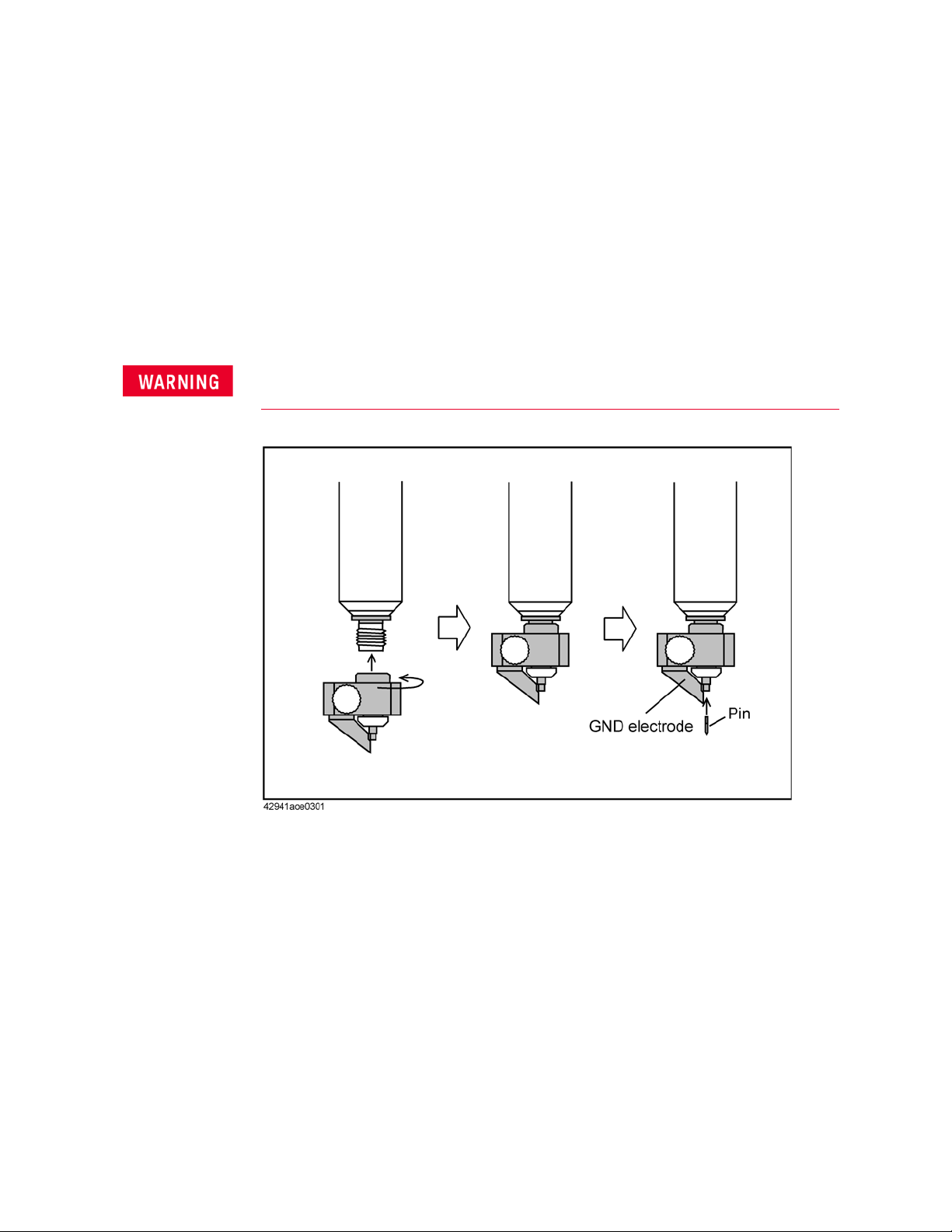
Connecting the Pin Probe
Attach the pin probe to the 3.5-mm connector top of the probe and insert the
pin.
The pin is sharp and potentially hazardous to personnel. When using or
changing, handle the pin probe with care to prevent injury.
Figure 3-1 Connecting the Pin Probe
Keysight 42941A Impedance Probe Kit 15
Page 16

Operation
Connecting the Probe Adapter
Connecting the Ground Lead
Remove the screw fixing the ground contact to detach the contact. Use the
removed screw to attach the ground lead to the pin probe.
Figure 3-2 Connecting the Ground Lead
16 Keysight 42941A Impedance Probe Kit
Page 17

Operation
Connecting the Probe Adapter
Connecting the BNC Adapter
Attach the BNC adapter to the 3.5-mm connector on top of the probe.
Figure 3-3 Connecting the BNC Adapter
Connecting the Clip Lead
Attach the BNC adapter to the probe and then attach the clip lead to the
adapter.
Figure 3-4 Connecting the Clip Lead
Keysight 42941A Impedance Probe Kit 17
Page 18

Operation
Fixture Compensation
Fixture Compensation
In an actual measurement, a probe adapter is attached to the probe. Fixture
compensation is required for compensating residual impedance and
admittance. The fixture compensation includes OPEN and SHORT
compensation measurements. For more information on fixture compensation,
also refer to the Operation Manual of the Impedance Analyzer.
Generally, there is no need to perform load compensation. However, if you
have a suitable standard device and require extremely accurate
measurements, perform load compensation as needed.
The following procedure is for measurement of the compensation data with the
42941A.
Performing Fixture Compensation
Attach the probe adapter to be used for your measurement and perform fixture
compensation.
1. Press the [Cal] key to bring up the Calibration Menu.
2. Press the Fixture Compen key to bring up the Fixture Compensation Menu.
18 Keysight 42941A Impedance Probe Kit
Page 19

Operation
Fixture Compensation
Performing Open Compensation
1. Attach the probe adapter to the probe but leave it disconnected from a
device.
Figure 3-5 Performing Open Compensation
2. Press the OPEN key to start the OPEN compensation data measurement.
When the OPEN compensation data measurement is completed, the softkey
label Open
[OFF] (if it is off) changes to Open [ON].
Keysight 42941A Impedance Probe Kit 19
Page 20

Operation
Fixture Compensation
Performing Short Compensation
1. Put the probe adapter into the SHORTed state as shown in Figure 3-6. Use
an appropriate device for shorting since no short device is supplied with the
BNC adapter.
For short compensation, we recommend using a short device with
gold-plated surfaces, which provide stable contact resistance.
Figure 3-6 Performing Short Compensation
2. Press the SHORT key to start the SHORT compensation data
measurement.When the SHORT compensation data measurement is
completed, the softkey label Short
20 Keysight 42941A Impedance Probe Kit
[OFF] (if it is off) changes to Short [ON].
Page 21

Operation
DUT Measurement
DUT Measurement
Before performing DUT measurement, open and short compensation should be
done as described in the previous sections.
DUT Measurement Using the Pin Probe
When measuring implemented circuits, mounted devices, and printed circuit
patterns, use the pin probe.
Figure 3-7 DUT Measurement Using the Pin Probe
The pin of the pin probe is replaceable. Replace it when damaged or dirty.
Keysight 42941A Impedance Probe Kit 21
Page 22

Operation
DUT Measurement
Adjusting the Pin-to-GND Gap
The gap between the pin and the GND contact is adjustable for DUT, ranging
from 0.5 mm to 13.5 mm. To adjust the gap, release the screw fastening the
GND contact and then rotate the contact (
The probe is grounded 25 W (nominally). Do not connect the probe directly
to the circuit with a DC output. If you connect a circuit with a DC output,
resulting in as follows.
It may cause the probe to be damaged.
It may influence the circuit to not perform correctly or may damage it entirely.
Measurement value will be incorrect.
In the case of measuring a circuit that could output a DC signal, connect an
appropriate DC-blocking capacitor to the probe.
Figure 3-8 Adjusting the Pin-to-GND Gap
Figure 3-8).
22 Keysight 42941A Impedance Probe Kit
Page 23

Operation
DUT Measurement
DUT Measurement Using the Ground Lead
Use the ground lead to ground the probe to a distant point (Figure 3-9). When
you attach the ground lead to the pin probe, detach the ground contact (refer
to
Figure 3-2).
Figure 3-9 DUT Measurement Using the Ground Lead
Keysight 42941A Impedance Probe Kit 23
Page 24

Operation
DUT Measurement
DUT Measurement Using the BNC Adapter
The BNC adapter is used to measure I/O terminals or cables that have BNC
connectors. It is also used as a mounting base for the alligator lead.
Figure 3-10 DUT Measurement Using the BNC Adapter
DUT Measurement Using the Clip Lead
Use the clip lead to measure devices with leads that are large or mounted on
the circuit board.
Figure 3-11 DUT Measurement Using the Clip Lead
24 Keysight 42941A Impedance Probe Kit
Page 25

Specifications
Specifications
4 Specifications
This chapter provides specifications of the 42941A test fixture.
Specifications
Applicable Instruments Impedance Analyzer
Frequency 40 Hz to 120 MHz
Maximum Voltage ± 42 V peak max. (AC+DC)
Output Impedance 25 Ω (Nominal) DC coupled
Operating
Environment
Non-operating
Environment
Dimensions 350 (W) × 100 (H) × 280 (D) mm
Weight 2400 g (four-terminal pair connection block 1000 g)
Safety Standards EN61010-1:1993 +A2:1995
For more information on impedance measurement accuracy at the
3.5-mm port and additional error factor, refer to the Operation Manual of the
Impedance Analyzer.
temp. –20 °C to +75 °C (except four-terminal pair connection
block)
0 °C to +55 °C (four-terminal pair connection block)
humidity 15% to 95% RH (@ wet bulb temp. < 40 °C)
temp. –40 °C to +70 °C
humidity ≤ 90% RH (@ wet bulb temp. < 65 °C)
(includes carrying case)
IEC61010-1:1990 +A1:1992 +A2:1995
CSA C22.2 No.1010.1:1992
INSTALLATION CATEGORY I
POLLUTION DEGREE 2
INDOOR USE
Keysight 42941A Impedance Probe Kit 5
Page 26

Specifications
Specifications
6 Keysight 42941A Impedance Probe Kit
Page 27

5 Service
Service
Maintenance
This chapter provides information on servicing and proper maintenance.
Serial Number for Non-RoHS 42941A: “MY431xxxxx and below” / “SG431xxxxx
and below”
Serial Number for RoHS 42941A: “MY432xxxxx and above” / “SG432xxxxx and
above”
Maintenance
An exploded view of the 42941A for parts identification is shown in Figure 5-1
and Figure 5-2. Due to limited availability of RoHS compliance station and
technical difficulties in RoHS soldering, only parts and support level that do
not require RoHS soldering are supported. Replace all defective parts with the
"RoHS Compliant Replacement Part No.". Do not disassemble any further than
shown. Maintenance consists principally of cleaning contacts and replacing
worn or damaged parts. Take special care when cleaning contacts.
To order parts, use the Keysight Technologies part numbers listed in Table 5-1
and Table 5-2. If a faulty part is located in an assembly that cannot be
disassembled, order the next higher assembly or return the fixture to the
nearest Keysight Technologies Sales/Service Office for repair or replacement.
Keysight 42941A Impedance Probe Kit 7
Page 28

Service
Maintenance
Figure 5-1 Replaceable Parts (part 1 of 2)
8 Keysight 42941A Impedance Probe Kit
Page 29

Service
Maintenance
Table 5-1 Replaceable Parts (part 1 of 2)
Reference
Designator
Part No.
1 42941-60001 42941-60601 1 PROBE
2 42941-65001 42941-60601 1 CHASSIS
3 42941-24001 42941-24001 1 COVER
4 42941-24015 42941-24015 1 KNOB
5 42941-24013 42941-24013 1 GND
6 - - 1 CANTACT PROBE
7 42941-60002 42941-60002 1 CONTACT ASSY
ROHS
Compliant
Replacement
Part No.
Qty. Description
8 0515-1718 0515-0382 4 SCR M4X12
9 0515-0914 0515-1946 2 SCR-MACH M3X0.5
10 42941-61602 42941-61672 1 RF CBL ASSY
11 1400-0719 1400-3284 4 CABLE TIE
0515-1718 0515-0382 4 SCR M4X12
12
3050-0893 3050-0893 4 WSHR-FL
13 42941-61604 42941-61674 1 RF CBL ASSY
14 42941-24006 42941-24006 1 PLATE
15 42941-66501 42941-66601 1 BOARD
16 0515-1550 0515-0372 2 SCR M3-L 8 P-H
17 42941-24005 42941-24005 1 BLOCK
Keysight 42941A Impedance Probe Kit 9
Page 30

Service
Maintenance
Figure 5-2 Replaceable Parts (part 2 of 2)
10 Keysight 42941A Impedance Probe Kit
Page 31

Service
Maintenance
Table 5-2 Replaceable Parts (part 2 of 2)
Reference
Designator
Part No. ROHS
Compl iant
Qty. Description
Replacement
Part No.
1 42941-00601 42941-00601 1 COVER TOP
2 42941-40002 42941-40002 2 BUSHING
3 1253-0476 5012-8630 4 ADPT BNC-SMB
4 3050-0067 3050-0067 4 WSHR-FL MTLC
5 3050-0789 3050-0789 4 WSHR-FL NM
6 42941-25002 42941-25002 2 SLEEVE
7 2950-0054 2950-0054 2 NUT-HEX-DBL-CHAM
8 2190-0054 2190-0054 2 WSHR-LK INTL T
9 0515-0914 0515-1946 2 SCR-MACH M3X0.5
10 16047-40002 16047-40002 4 INSULATOR
11 42942-25006 42942-25006 1 GUIDE BNC
12 0515-1551 0515-0374 2 SCR M3-L 8 P-H
13 42942-00603 42942-00603 1 COVER
14 42941-24003 42941-24003 2 GUIDE
15 0515-0914 0515-1946 2 SCR-MACH M3X0.5
16 42941-00602 42941-00602 1 COVER BOTTOM
17 1460-2615 1460-2615 2 SPRING
18 42941-24004 42941-24004 2 SHAFT
19 0510-0083 0510-0083 2 RTNR-R
Keysight 42941A Impedance Probe Kit 11
Page 32

Service
Maintenance
12 Keysight 42941A Impedance Probe Kit
Page 33

This information is subject to change without notice.
© Keysight Technologies 1999 - 2019
Edition 5, August 2, 2019
*42941-90010*
42941-90010
www.keysight.com
 Loading...