

Page 1

Keysight 11713D/E
Attenuator/Switch Driver
Operating and
Service Manual
Page 2

Notices
CAUTION
WARNING
Copyright Notice
© Keysight Technologies 2020
No part of this manual may be reproduced in
any form or by any means (including electronic
storage and retrieval or translation into a foreign language) without prior agreement and
written consent from Keysight Technologies as
governed by United States and international
copyright laws.
Manual Part Number
11713-90028
Edition
Edition 3, December 1, 2020
Printed in:
Printed in Malaysia
Published by:
Keysight Technologies
Bayan Lepas Free Industrial Zone,
11900 Penang, Malaysia
Technology Licenses
The hardware and/or software described in
this document are furnished under a license
and may be used or copied only in accordance
with the terms of such license.
Declaration of Conformity
Declarations of Conformity for this product
and for other Keysight products may be downloaded from the Web. Go to http://www.key-
sight.com/go/conformity. You can then search
by product number to find the latest Declaration of Conformity.
U.S. Government Rights
The Software is “commercial computer software,” as defined by Federal Acquisition Regulation (“FAR”) 2.101. Pursuant to FAR 12.212
and 27.405-3 and Department of Defense FAR
Supplement (“DFARS”) 227.7202, the U.S.
government acquires commercial computer
software under the same terms by which the
software is customarily provided to the public.
Accordingly, Keysight provides the Software to
U.S. government customers under its standard
commercial license, which is embodied in its
End User License Agreement (EULA), a copy of
which can be found at http://www.key-
sight.com/find/sweula. The license set forth in
the EULA represents the exclusive authority by
which the U.S. government may use, modify,
distribute, or disclose the Software. The EULA
and the license set forth therein, does not
require or permit, among other things, that
Keysight: (1) Furnish technical information
related to commercial computer software or
commercial computer software documentation that is not customarily provided to the
public; or (2) Relinquish to, or otherwise provide, the government rights in excess of these
rights customarily provided to the public to
use, modify, reproduce, release, perform, display, or disclose commercial computer software or commercial computer software
documentation. No additional government
requirements beyond those set forth in the
EULA shall apply, except to the extent that
those terms, rights, or licenses are explicitly
required from all providers of commercial
computer software pursuant to the FAR and
the DFARS and are set forth specifically in
writing elsewhere in the EULA. Keysight shall
be under no obligation to update, revise or
otherwise modify the Software. With respect
to any technical data as defined by FAR 2.101,
pursuant to FAR 12.211 and 27.404.2 and
DFARS 227.7102, the U.S. government
acquires no greater than Limited Rights as
defined in FAR 27.401 or DFAR 227.7103-5 (c),
as applicable in any technical data.
Warranty
THE MATERIAL CONTAINED IN THIS DOCUMENT IS PROVIDED “AS IS,” AND IS SUBJECT
TO BEING CHANGED, WITHOUT NOTICE, IN
FUTURE EDITIONS. FURTHER, TO THE MAXIMUM EXTENT PERMITTED BY APPLICABLE
LAW, KEYSIGHT DISCLAIMS ALL WARRANTIES, EITHER EXPRESS OR IMPLIED, WITH
REGARD TO THIS MANUAL AND ANY INFORMATION CONTAINED HEREIN, INCLUDING
BUT NOT LIMITED TO THE IMPLIED WARRANTIES OF MERCHANTABILITY AND FITNESS
FOR A PARTICULAR PURPOSE. KEYSIGHT
SHALL NOT BE LIABLE FOR ERRORS OR FOR
INCIDENTAL OR CONSEQUENTIAL DAMAGES
IN CONNECTION WITH THE FURNISHING,
USE, OR PERFORMANCE OF THIS DOCUMENT OR OF ANY INFORMATION CONTAINED
HEREIN. SHOULD KEYSIGHT AND THE USER
HAVE A SEPARATE WRITTEN AGREEMENT
WITH WARRANTY TERMS COVERING THE
MATERIAL IN THIS DOCUMENT THAT CONFLICT WITH THESE TERMS, THE WARRANTY
TERMS IN THE SEPARATE AGREEMENT
SHALL CONTROL.
Safety Information
A CAUTION notice denotes a hazard. It calls
attention to an operating procedure, practice,
or the like that, if not correctly performed or
adhered to, could result in damage to the
product or loss of important data. Do not proceed beyond a CAUTION notice until the indicated conditions are fully understood and met.
A WARNING notice denotes a hazard. It calls
attention to an operating procedure, practice,
or the like that, if not correctly performed or
adhered to, could result in personal injury or
death. Do not proceed beyond a WARNING
notice until the indicated conditions are fully
understood and met.
2 Keysight 11713D/E Operating and Service Manual
Page 3

Certification
Keysight Technologies certifies that this product met its published specifications at the time of
shipment from the factory. Keysight Technologies further certifies that its calibration
measurements are traceable to the United States National Institute of Standards and Technology
(NIST, formerly NBS), to the extend allowed by the Institute’s calibration facility, and to the
calibration facilities of the other International Standards Organization members.
Keysight 11713D/E Operating and Service Manual 3
Page 4

Safety Considerations
WARNING
WARNING
WARNING
WARNING
WARNING
WARNING
The following general safety precautions must be observed during all phases of operation, service,
and repair of this instrument. Failure to comply with these precautions or with specific warnings
elsewhere in this manual violates safety standards of design, manufacture, and intended use of the
instrument. Keysight Technologies assumes no liability for the customer's failure to comply with
these requirements.
BEFORE APPLYING POWER
– Verify that the correct fuse is installed.
– Ensure the mains supply voltage fluctuation do not exceed ±10% of the nominal supply
voltage.
GROUND THE INSTRUMENT
This product is a Safety Class I instrument (provided with a protective earth terminal). To
minimize shock hazard, the instrument chassis and cabinet must be connected to an
electrical ground. The instrument must be connected to the AC power supply mains through
a three-conductor power cable, with the third wire firmly connected to an electrical ground
(safety ground) at the power outlet. Any interruption of the protective (grounding)
conductor or disconnection of the protective earth terminal will cause a potential shock
hazard that could result in personal injury. If the instrument is to be energized via an
external autotransformer for voltage reduction, be certain that the autotransformer
common terminal is connected to the neutral (earthed pole) of the AC power lines (supply
mains).
DO NOT OPERATE IN AN EXPLOSIVE ATMOSPHERE OR WET ENVIRONMENTS
Do not operate the device around flammable gases or fumes, vapor, or wet environments.
DO NOT OPERATE DAMAGED OR DEFECTIVE INSTRUMENTS
Instruments that appear damaged or defective should be made inoperative and secured
against unintended operation until they can be repaired by qualified service personnel.
DO NOT SUBSTITUTE PARTS OR MODIFY INSTRUMENT
Because of the danger of introducing additional hazards, do not install substitute parts or
perform any unauthorized modification to the instrument. Return the instrument to a
Keysight Technologies Sales and Service Office for service and repair to ensure that safety
features are maintained.
USE THE POWER CORD PROVIDED
Use the device with the power cord provided with the shipment.
4 Keysight 11713D/E Operating and Service Manual
Page 5
WARNING
USE THE DEVICE AS SPECIFIED
WARNING
CAUTION
CAUTION
If the device is used in a manner not specified by manufacturer, the device protection may
be impaired.
Keysight 11713D/E attenuator/switch drivers are designed for indoor use and in an area
with low condensation.
CLEAN WITH SLIGHTLY DAMPENED CLOTH
Clean the outside of the instrument with a soft, lint-free, slightly dampened cloth. Do not
use detergent, volatile liquids, or chemical solvents.
The instrument is designed for use in Overvoltage Category II and Pollution Degree 2.
Safety Symbols
The following symbols on the instrument and in the documentation indicate precautions which
must be taken to maintain safe operation of the instrument.
When you see this symbol on your instrument,
you should refer to the instrument’s instruction
manual for important information.
This symbol indicates the protective earth
(ground) terminal.
This symbol indicates that the instrument
requires alternating current (ac) input.
This symbol indicates the Fuse.
Keysight 11713D/E Operating and Service Manual 5
Page 6
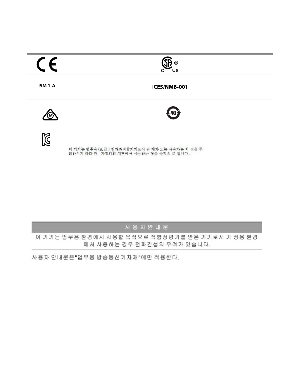
Regulatory Markings
R-R-Kst-WN19609
The CE mark is a registered trademark of the
European Community. If it is accompanied by a
year, it indicates the year the design was proven.
This text indicates that the instrument is an
Industrial Scientific and Medical Group 1 Class A
product (CISPR 11, Clause 4).
The RCM mark is a registered trademark of the
Australian Communications and Media Authority.
This symbol is a South Korean Class A EMC Declaration.
This equipment is Class A suitable for professional use and is for use in electromagnetic environments outside of the home.
South Korean Class A EMC Declaration
Information to the user:
This instrument has been conformity assessed for use in business environments. In a residential
environment, this equipment may cause radio interference.
This EMC statement applies to the equipment only for use in business environment.
The CSA mark is a registered trademark of the
Canadian Standards Association.
ICES/NMB-001 indicates that this ISM device
complies with the Canadian ICES-001.
Cet appareil ISM est conforme a la norme
NMB-001 du Canada.
This symbol indicates the time period during
which no hazardous or toxic substance elements
are expected to leak or deteriorate during normal
use. Forty years is the expected useful life of the
product.
Safety and EMC Requirements
6 Keysight 11713D/E Operating and Service Manual
This instrument is designed to comply with the following safety and EMC (Electromagnetic
Compatibility) requirements:
– Low Voltage Directive 2014/35/EU
– EMC Directive 2014/30/EU
Page 7

Waste Electrical and Electronic Equipment (WEEE) Directive
This instrument complies with the WEEE Directive marking requirement. This affixed product label
indicates that you must not discard this electrical or electronic product in domestic household
waste.
Product category:
With reference to the equipment types in the WEEE directive Annex 1, this instrument is classified
as a “Monitoring and Control Instrument” product.
The affixed product label is as shown below.
Do not dispose in domestic household waste.
To return this unwanted instrument, contact your nearest Keysight Service Center, or visit
http://about.keysight.com/en/companyinfo/environment/takeback.shtml for more information.
Sales and Technical Support
To contact Keysight for sales and technical support, refer to the support links on the following
Keysight websites:
– www.keysight.com/find/11713
(product-specific information and support, software and documentation updates)
– www.keysight.com/find/assist
(worldwide contact information for repair and service)
Keysight 11713D/E Operating and Service Manual 7
Page 8

THIS PAGE HAS BEEN INTENTIONALLY LEFT BLANK
8 Keysight 11713D/E Operating and Service Manual
Page 9

Table of Contents
Certification . . . . . . . . . . . . . . . . . . . . . . . . . . . . . . . . . . . . . . . . . . . . . . . . . . . . . . . . . . . . 3
Safety Considerations . . . . . . . . . . . . . . . . . . . . . . . . . . . . . . . . . . . . . . . . . . . . . . . . . . . . 4
Safety Symbols . . . . . . . . . . . . . . . . . . . . . . . . . . . . . . . . . . . . . . . . . . . . . . . . . . . . . . . . . 5
Regulatory Markings . . . . . . . . . . . . . . . . . . . . . . . . . . . . . . . . . . . . . . . . . . . . . . . . . . . . . 6
South Korean Class A EMC Declaration . . . . . . . . . . . . . . . . . . . . . . . . . . . . . . . . . . . . . 6
Safety and EMC Requirements . . . . . . . . . . . . . . . . . . . . . . . . . . . . . . . . . . . . . . . . . . . . 6
Waste Electrical and Electronic Equipment (WEEE) Directive . . . . . . . . . . . . . . . . . . . . 7
Sales and Technical Support . . . . . . . . . . . . . . . . . . . . . . . . . . . . . . . . . . . . . . . . . . . . . . 7
1Introduction
Key Features of Keysight 11713D/E Attenuator/Switch Driver . . . . . . . . . . . . . . . . . . . 16
Compatible Keysight Attenuators and Switches . . . . . . . . . . . . . . . . . . . . . . . . . . . . . . 16
Connecting Accessories . . . . . . . . . . . . . . . . . . . . . . . . . . . . . . . . . . . . . . . . . . . . . . . . . 17
11713D Front and Rear Panels at a Glance . . . . . . . . . . . . . . . . . . . . . . . . . . . . . . . . . . 19
11713E Front and Rear Panels at a Glance . . . . . . . . . . . . . . . . . . . . . . . . . . . . . . . . . . 21
2Installation
Initial Inspection . . . . . . . . . . . . . . . . . . . . . . . . . . . . . . . . . . . . . . . . . . . . . . . . . . . . . . . 26
Preparing for Use . . . . . . . . . . . . . . . . . . . . . . . . . . . . . . . . . . . . . . . . . . . . . . . . . . . . . . 27
Connecting to Keysight Attenuators and Switches . . . . . . . . . . . . . . . . . . . . . . . . . . . . 28
3 Specifications
General Specifications . . . . . . . . . . . . . . . . . . . . . . . . . . . . . . . . . . . . . . . . . . . . . . . . . . 36
Environmental Specifications . . . . . . . . . . . . . . . . . . . . . . . . . . . . . . . . . . . . . . . . . . . . . 37
4 Verification
Operator’s Check for Local Operation . . . . . . . . . . . . . . . . . . . . . . . . . . . . . . . . . . . . . . 40
Operator’s Check for Remote Operation . . . . . . . . . . . . . . . . . . . . . . . . . . . . . . . . . . . . 41
5 Local Operations
Getting Started with the 11713D/E . . . . . . . . . . . . . . . . . . . . . . . . . . . . . . . . . . . . . . . . 44
Main Menu of the 11713D/E . . . . . . . . . . . . . . . . . . . . . . . . . . . . . . . . . . . . . . . . . . . . . 53
Save/Recall State Menu . . . . . . . . . . . . . . . . . . . . . . . . . . . . . . . . . . . . . . . . . . . . . . . . . 60
6 Remote Operations
Configuring Remote Interface . . . . . . . . . . . . . . . . . . . . . . . . . . . . . . . . . . . . . . . . . . . . 64
Control using Keysight IO Libraries Suite . . . . . . . . . . . . . . . . . . . . . . . . . . . . . . . . . . . 66
Programming Guide (SCPI) . . . . . . . . . . . . . . . . . . . . . . . . . . . . . . . . . . . . . . . . . . . . . . 67
7 Remote Interface Configurations
Connecting the 11713D/E to your Computer . . . . . . . . . . . . . . . . . . . . . . . . . . . . . . . . 92
Keysight 11713D/E Operating and Service Manual 9
Page 10

Exploring the 11713D/E Web Interface over LAN . . . . . . . . . . . . . . . . . . . . . . . . . . . . . 98
8 Servicing the Attenuator/Switch Driver
Preparing a Static-Safe Workstation . . . . . . . . . . . . . . . . . . . . . . . . . . . . . . . . . . . . . . 102
Maintenance and Adjustments . . . . . . . . . . . . . . . . . . . . . . . . . . . . . . . . . . . . . . . . . . 103
10 Keysight 11713D/E Operating and Service Manual
Page 11

List of Figures
Figure 1-1 11713D front panel features . . . . . . . . . . . . . . . . . . . . . . . . . . . . . . . . 19
Figure 1-2 11713D rear panel features . . . . . . . . . . . . . . . . . . . . . . . . . . . . . . . . . 20
Figure 1-3 11713E front panel features . . . . . . . . . . . . . . . . . . . . . . . . . . . . . . . . 21
Figure 1-4 11713E rear panel features . . . . . . . . . . . . . . . . . . . . . . . . . . . . . . . . . 23
Figure 2-1 Handle positioning for bench operation . . . . . . . . . . . . . . . . . . . . . . . 27
Figure 2-2 Typical connection for a programmable four-section attenuator . . . . 31
Figure 2-3 Typical connection for 8762 and 8765 series coaxial switches . . . . . 32
Figure 2-4 Typical connection for relay driving circuit . . . . . . . . . . . . . . . . . . . . . 33
Figure 4-1 Switching system for verification . . . . . . . . . . . . . . . . . . . . . . . . . . . . . 40
Figure 6-1 Example of control using Keysight IO Libraries Suite . . . . . . . . . . . . . 66
Figure 7-1 11713D/E Web Interface’s Welcome Window . . . . . . . . . . . . . . . . . . 99
Figure 7-2 Navigation bar . . . . . . . . . . . . . . . . . . . . . . . . . . . . . . . . . . . . . . . . . . . 99
Figure 7-3 Enable Password window . . . . . . . . . . . . . . . . . . . . . . . . . . . . . . . . . . 100
Keysight 11713D/E Operating and Service Manual 11
Page 12

THIS PAGE HAS BEEN INTENTIONALLY LEFT BLANK
12 Keysight 11713D/E Operating and Service Manual
Page 13

List of Tables
Table 1-1 Key features of 11713D/E . . . . . . . . . . . . . . . . . . . . . . . . . . . . . . . . . . 16
Table 1-2 Compatible Keysight switches . . . . . . . . . . . . . . . . . . . . . . . . . . . . . . . 17
Table 1-3 Compatible Keysight attenuators . . . . . . . . . . . . . . . . . . . . . . . . . . . . 17
Table 1-4 Connecting accessories for Keysight 11713D/E . . . . . . . . . . . . . . . . . 18
Table 2-1 Summary of switches and attenuators connections to 11713D/E . . . 28
Table 2-2 11713D/E front panel and back panel properties . . . . . . . . . . . . . . . . 30
Table 3-1 11713D/E supplemental characteristics . . . . . . . . . . . . . . . . . . . . . . . 36
Table 3-2 11713D/E environmental specifications . . . . . . . . . . . . . . . . . . . . . . . 37
Table 4-1 Recommended test equipment . . . . . . . . . . . . . . . . . . . . . . . . . . . . . . 40
Table 5-1 Connection between 11713D/E and programmable attenuators . . . 51
Table 5-2 Connection between 11713D/E and switches . . . . . . . . . . . . . . . . . . 51
Table 6-1 Bit configuration of Standard Event Status Enable register . . . . . . . . 85
Table 6-2 Bit configuration of Status Byte Enable register . . . . . . . . . . . . . . . . . 88
Keysight 11713D/E Operating and Service Manual 13
Page 14

THIS PAGE HAS BEEN INTENTIONALLY LEFT BLANK
14 Keysight 11713D/E Operating and Service Manual
Page 15

Keysight 11713D/E Attenuator/Switch Driver
Operating and Service Manual
1 Introduction
Key Features of Keysight 11713D/E Attenuator/Switch Driver 16
Compatible Keysight Attenuators and Switches 16
Connecting Accessories 18
11713D Front and Rear Panels at a Glance 20
11713E Front and Rear Panels at a Glance 22
This chapter provides an overview of the Keysight 11713D/E attenuator/switch drivers which
includes the instruments’ functions and capabilities, compatibility with Keysight switching
components, and physical appearances.
15
Page 16

1Introduction
NOTE
Key Features of Keysight 11713D/E Attenuator/Switch Driver
The 11713D attenuator/switch driver is a GPIB/USB/LAN compatible instrument that concurrently
drives up to two four-section programmable step attenuators and two microwave coaxial switches,
or up to 10 SPDT switches.
The 11713E attenuator/switch driver is a GPIB/USB/LAN compatible instrument that concurrently
drives up to four four-section programmable step attenuators and four microwave coaxial switches,
or up to 20 SPDT switches. The 11713E comes with tri-voltage selection of +5 V, +15 V and +24 V
and also permits user-defined voltage supply capability.
The 11713D/E attenuator/switch drivers output continuous current and
support pulse drive. Please ensure your switching devices can withstand
continuous current or have a built-in current interrupt feature.
Tab le 1-1 Key features of 11713D/E
Key features 11713D 11713E
Manually-controlled using front panel push buttons Yes Yes
Automatically-control through:
–GPIB
–USB
–LAN
Yes
Yes
Yes
Yes
Yes
Yes
Integrated LCD display Yes Yes
Self-contained power supply with current limiting Yes Yes
Common terminal supplies of:
– +5 Vdc
–+15 Vdc
– +24 Vdc
– User-defined
TTL control
[a] For 11713E, maximum user-defined voltage supply is 28 Vdc.
[b] This TTL specification is 2.4 V at 1 mA.
[a]
[b]
Compatible Keysight Attenuators and Switches
The 11713D/E attenuator/switch drivers are designed to drive the following Keysight attenuators
and switches. If you are using attenuators and switches made by another supplier, check the
switching characteristics against those specified in Chapter 3, "Specifications". Refer to Keysight
11713D/E Configuration Guide, available at www.keysight.com/find/11713, for the most updated
list.
No
No
Yes
No
No Yes
Yes
Yes
Yes
Yes
16 Keysight 11713D/E Operating and Service Manual
Page 17

Table 1-2 Compatible Keysight switches
Introduction 1
Keysight model number
8765A/B/C/D/F (33314A/B/D), N1810UL SPDT, unterminated
8762A/B/C/F (33311A/B/C), N1810TL SPDT, terminated
8763A/B/C (33312A/B/C), N1811TL Bypass, 4-port, terminated
8764A/B/C (33313A/B/C), N1812UL Bypass, 5-port, unterminated
8766K (33366K) SP3T, unterminated
8767K (33367K), 8767M, L7204A/B/C SP4T, unterminated
87104A/B/C/D/P/Q/R, 87204A/B/C, L7104A/B/C SP4T, terminated
8768K (33368K), 8768M SP5T, unterminated
8769K (33369K), 8769M, L7206A/B/C SP6T, unterminated
87106A/B/C/D/P/Q/R, 87206A/B/C, L7106A/B/C SP6T, terminated
87222C/D/E, L7222C DPDT (transfer), unterminated
87406B Matrix, 4-port, terminated
87606B Matrix, 6-port, terminated
U9397A/C SPDT, terminated, solid state
U9400A/C SPDT, terminated, solid state
P9400A/C SPDT, terminated, solid state
P9402A/C SPDT, terminated, solid state
P9404A/C SP4T, terminated, solid state
Description
[a]
U7104E/F/N SP4T, terminated
U7106E/F/N SP6T, terminated
U7108A/B/C SP8T, terminated
U7110A/B/C SP10T, terminated
[a] * Electromechanical switches unless specified
Table 1-3 Compatible Keysight attenuators
Keysight model number Description
8494G/H (33320G/H), 84904K/L/M (33324K/L) 11 dB, 1 dB steps
8495G/H/K (33321 G/H/K), 84907K/L (33327K/L) 70 dB, 10 dB steps
8496G/H (33322G/H) 110 dB, 10 dB steps
8497K (33323K), 84906K/L (33326K/L) 90 dB, 10 dB steps
84905M 60 dB, 10 dB steps
84908M 65 dB, 5 dB steps
Keysight 11713D/E Operating and Service Manual 17
Page 18

1Introduction
Connecting Accessories
Various types of connecting accessories are available to drive Keysight attenuators and switches
using the 11713D/E attenuator/switch drivers. Tab le 1-4 lists the available accessories.
Tab le 1-4 Connecting accessories for Keysight 11713D/E
Connecting accessories Description
11716A
11716C
11713D-102
11713E-102
11713D-103
11713E-103
11713D-104
11713E-104
11713D-105
11713E-105
11713D-106
11713E-106
11713D-107
11713E-107
11713D-001
11713E-001
11713D-101
11713E-101
11713D-201
11713E-201
11713D-301
11713E-301
11713D-401
11713E-401
11713D-501
11713E-501
11713D-502
11713E-502
11713D-601
11713E-601
11713D-701
11713E-701
Interconnect kit (Type-N connectors)
Interconnect kit (SMA connectors)
11713-60068, Viking connector to 4 cables with 4-conductor bare wires
11713-60069, Viking connector to 2 cables with 5-conductor bare wires
11713-60071, Viking connector to 4 cables with 3-pin connector
11713-60072, Viking connector to 4 cables with 3-conductor bare wires
11713-60073, Dual Viking connector to 24-pin connector
11713-60074, Triple Viking connector to 24-pin connector
11764-60004, Viking connector to 10-pin DIP connector, 60 inches long
8120-2703, Viking connector to Viking connector, 60 inches long
5061-0969, Viking connector to 12-pin conductor cable, bare wire (for five switches), 60
inches long
11761-60001, Viking connector to (4) ribbon cables, connect up to four switches, 60
inches long
11713-60042, Dual Viking connector to 16-pin DIP connector, 60 inches long
11713-60043, Viking connector to (4) 9-pin Dsub connectors, connect up to four
switches, 60 inches long
11713-60043, Viking connector to (2) 9-pin Dsub connectors, connect up to 2 switches,
60 inches long
11713-60044, Viking connector to 16-pin DIP connector, 60 inches long
5064-7848, Viking connector to 14-pin DIP connector, 60 inches long
[a]
[a]
11713D-801
11713E-801
11713-60047, Viking connector to (4) 10-pin DIP connectors, connect up to 4 switches,
50 inches long
18 Keysight 11713D/E Operating and Service Manual
Page 19

Table 1-4 Connecting accessories for Keysight 11713D/E
Connecting accessories Description
Introduction 1
11713D-908
11713E-908
11713D-909
11713E-909
[a] Order this kit to connect two programmable step attenuators in series
1CM124A, Rack mount kit for one instrument
5061-9694 & 1CM107A, rack mount kit for two instruments
For the configuration details, refer to Keysight 11713D/E Configuration Guide available at
www.keysight.com/find/11713.
Keysight 11713D/E Operating and Service Manual 19
Page 20
1Introduction
1 2
3
4
5
6
7
89
10
11
12
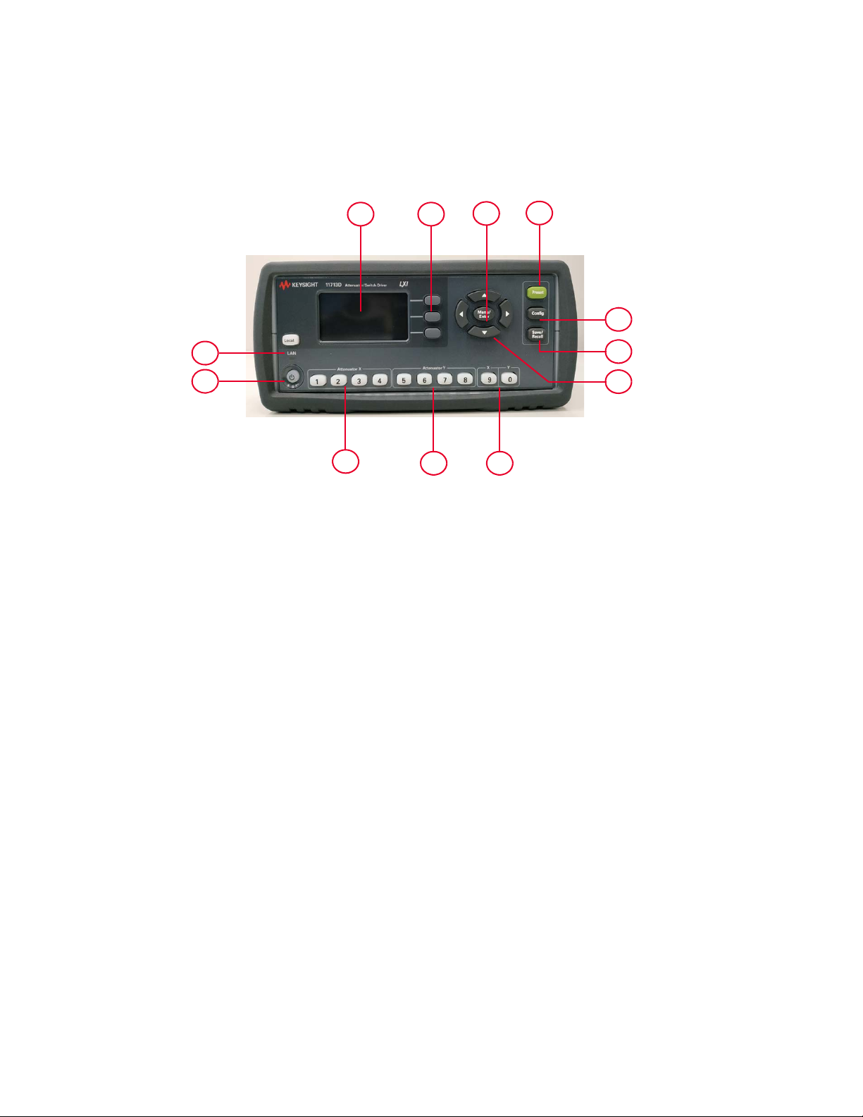
11713D Front and Rear Panels at a Glance
This section briefly describes the function of the front panel keys of 11713D.
Figure 1-1 11713D front panel features
1LCD screen
2Softkeys: These unmarked keys are referred to by the text on display next to them.
3Menu/Enter: Press this key to select the highlighted parameter On/Off or select the highlighted
field or go back to the main menu.
4Preset: Press this key to preset the driver.
5Config: Press this key to access the configuration menu. You can set the attenuator type, supply
voltage, and TTL condition through this menu.
6Save/Recall: Press this key to save current settings or recall saved settings.
7Navigation buttons: The arrow keys are used to navigate parameters displayed on the LCD
screen or change parameters such as GPIB address.
8Switches: In the local mode, pushbutton switches 9 and 0 change the position of a coaxial
switch connected to rear panel banana jacks S9 A/B and S0 A/B respectively.
9Attenuator Y: In the local mode, pushbuttons 5, 6, 7, and 8 change the attenuation setting of an
attenuator or change the position of coaxial switch(es) connected to the ATTEN Y connector on
the rear panel.
10 Attenuator X: In the local mode, pushbuttons 1, 2, 3, and 4 change the attenuation setting of
an attenuator or change the position of coaxial switch(es) connected to the ATTEN X connector
on the rear panel.
11 On/Standby: Press this key to switch between on and standby. When power is supplied, the
background LED is red. Pressing the key once switches the driver on and the background LED
turns to green.
12 Local: Press this key to control the driver from the front panel when it is operating via the
remote interfaces.
20 Keysight 11713D/E Operating and Service Manual
Page 21
Introduction 1
2
4
7
8
9
10
5 6
1
3
11
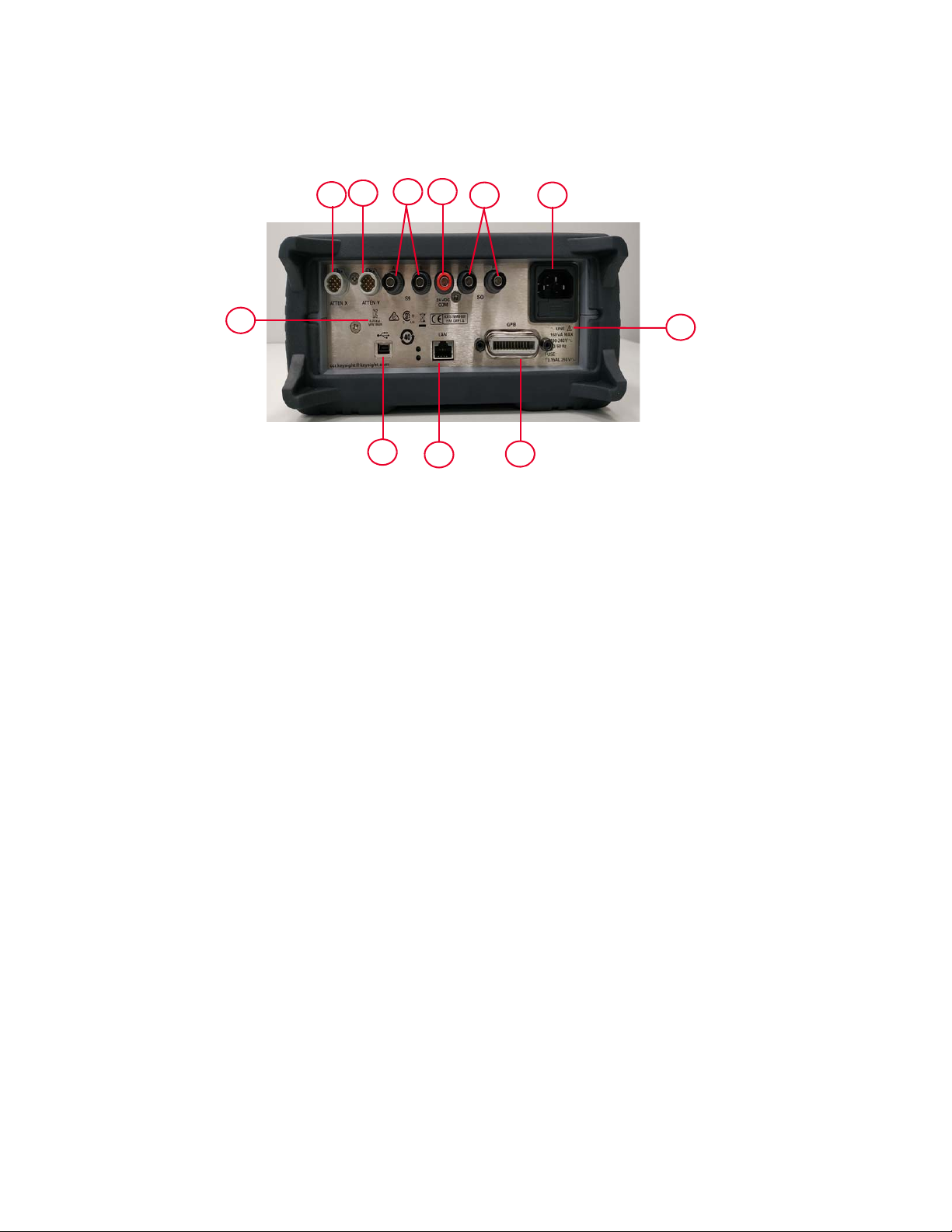
This section briefly describes the function of the rear panel connectors of 11713D.
Figure 1-2 11713D rear panel features
1 ATTEN X: Viking connector for connection to attenuator or switch(es).
2 ATTEN Y: Viking connector for connection to attenuator or switch(es).
3S9 A/B: Banana jack connectors for connection to coaxial switch.
4 24 VDC COM: Banana jack connector to provide common +24 Vdc in driving the coaxial
switches connected to S9 and/or S0.
5S0 A/B: Banana jack connectors for connection to coaxial switch.
6Receptacle: Matches transformer primary to line voltage via power cable.
7Alert symbol: This symbol is used to point out a necessary reference for the user.
8GPIB connector: The interface connector from a source device to a listening device for the
remote mode of operation.
9 LAN connector: The interface connector for LAN cable (option LXI only).
10 USB connector: The interface connector for Type mini B 5-pin USB cable (option LXI only).
11 Instrument markings
Keysight 11713D/E Operating and Service Manual 21
Page 22

1Introduction
1 2
3
4
5
6
7
8
9
10
11
12131415
16
17
11713E Front and Rear Panels at a Glance
This section briefly describes the function of the front panel keys of 11713E.
Figure 1-3 11713E front panel features
1LCD screen
2Softkeys: These unmarked keys are referred to by the text on display next to them.
3Navigation buttons: The arrow keys are used to navigate parameters displayed on the LCD
screen or change parameters such as GPIB address.
4Menu/Enter: Press this key to select the highlighted parameter On/Off or select the highlighted
field or go back to the main menu.
5Preset: Press this key to preset the driver.
6Config: Press this key to access the configuration menu. You can set the attenuator type, supply
voltage, and TTL condition through this menu.
7Save/Recall: Press this key to save current settings or recall saved settings.
8 Supply Voltage for Bank 1: Indicates supply voltage setting (background LED in red) for bank
1.
9 Supply Voltage for Bank 2: Indicates supply voltage setting (background LED in red) for bank
2.
10 Switches for Bank 1: In the local mode, pushbutton switches 9 and 0 change the position of a
coaxial switch connected to rear panel banana jacks S9 A/B and S0 A/B respectively, for bank
1.
11 Switches for Bank 2: In the local mode, pushbutton switches 9 and 0 change the position of a
coaxial switch connected to rear panel banana jacks S9 A/B and S0 A/B respectively for, bank
2.
12 Attenuator Y for Bank 1: In the local mode, pushbuttons 5, 6, 7, and 8 change the attenuation
setting of an attenuator or change the position of coaxial switch(es) connected to the ATTEN Y
connector on the rear panel, for bank 1.
22 Keysight 11713D/E Operating and Service Manual
Page 23

Introduction 1
13 Attenuator Y for Bank 2: In the local mode, pushbuttons 5, 6, 7, and 8 change the attenuation
setting of an attenuator or change the position of coaxial switch(es) connected to the ATTEN Y
connector on the rear panel, for bank 2.
14 Attenuator X for Bank 1: In the local mode, pushbuttons 1, 2, 3, and 4 change the attenuation
setting of an attenuator or change the position of coaxial switch(es) connected to the ATTEN X
connector on the rear panel, for bank 1.
15 Attenuator X for Bank 2: In the local mode, pushbuttons 1, 2, 3, and 4 change the attenuation
setting of an attenuator or change the position of coaxial switch(es) connected to the ATTEN X
connector on the rear panel, for bank 2.
16 On/Standby: Press this key to switch between on and standby. When power is supplied, the
background LED is red. Pressing the key once switches the driver on and the background LED
turns to green.
17 Local: Press this key to control the driver from the front panel when it is operating via the
remote interfaces.
Keysight 11713D/E Operating and Service Manual 23
Page 24
1Introduction
1
2
3
4
7
8
9
10
11
5
6
12
13
151617
14
18
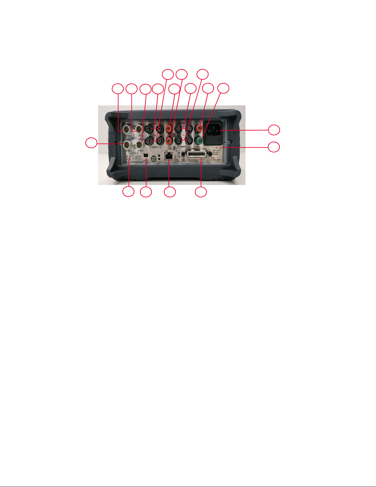
This section briefly describes the function of the rear panel connectors of 11713E.
Figure 1-4 11713E rear panel features
1ATTEN X Bank 1: Viking connector for connection to attenuator or switch(es), for bank 1.
2ATTEN X Bank 2: Viking connector for connection to attenuator or switch(es), for bank 2.
3 ATTEN Y Bank 1: Viking connector for connection to attenuator or switch(es), for bank 1.
4 ATTEN Y Bank 2: Viking connector for connection to attenuator or switch(es), for bank 2.
5 S9 A/B Bank 1: Banana jack connectors for connection to coaxial switch, for bank 1.
6 S9 A/B Bank 2: Banana jack connectors for connection to coaxial switch, for bank 2.
7VDC COM Bank 1: Banana jack connector to provide common Vdc in driving the coaxial
switches connected to S9 and/or S0, for bank 1.
8VDC COM Bank 2: Banana jack connector to provide common Vdc in driving the coaxial
switches connected to S9 and/or S0, for bank 2.
9 S0 A/B Bank 1: Banana jack connectors for connection to coaxial switch, for bank 1.
10 S0 A/B Bank 2: Banana jack connectors for connection to coaxial switch, for bank 2.
11 EXT (External) VDC: Banana jack connector to provide user-defined Vdc, for both banks.
12 GND (Ground): Banana jack connector to provide grounding, for both banks.
13 Receptacle: Matches transformer primary to line voltage via power cable.
14 Alert symbol: This symbol is used to point out a necessary reference for the user.
15 GPIB connector: The interface connector from a source device to a listening device for the
remote mode of operation.
16 LAN connector: The interface connector for LAN cable.
17 USB connector: The interface connector for Type mini B 5-pin USB cable.
18 Instrument markings
24 Keysight 11713D/E Operating and Service Manual
Page 25

Keysight 11713D/E Attenuator/Switch Driver
Operating and Service Manual
2 Installation
Initial Inspection 26
Preparing for Use 27
Connecting to Keysight Attenuators and Switches 28
This chapter provides you important information on how to unpack and check your instrument,
how to prepare your instrument for bench operation, and tips on configuring the 11713D/E with
Keysight attenuators and switches.
25
Page 26

2Installation
Initial Inspection
1 Unpack and inspect the shipping container and its contents thoroughly to ensure that nothing
was damaged during shipment. If the shipping container or cushioning material is damaged,
the contents should be checked both mechanically and electrically.
2 If the contents are damaged or defective, contact your nearest Keysight Technologies Service
and Support Office. Refer to “Sales and Technical Support” on page 7. Keysight Technologies
will arrange for repair or replacement of the damaged or defective equipment. Keep the
shipping materials for the carrier's inspection.
3 If you are returning your instrument for service, repackaging the attenuator/switch driver
requires original shipping containers and materials or their equivalents. Keysight Technologies
can provide packaging materials identical to the original materials. Refer to “Sales and
Technical Support” on page 7 for the Keysight Technologies nearest to you.
26 Keysight 11713D/E Operating and Service Manual
Page 27
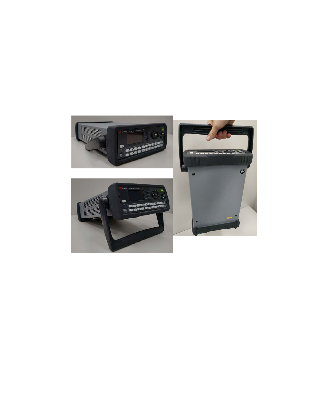
Preparing for Use
Bench operation
Pull the handle outwards, and adjust it into one of the two positions illustrated in Figure 2-1.
– (Top) Handle placed underneath the instrument to assure self- alignment of the instruments
when stacked.
– (Bottom) Handle tilted to raise the front of the instrument for easier viewing of the front panel.
Installation 2
Figure 2-1 Handle positioning for bench operation
Keysight 11713D/E Operating and Service Manual 27
Page 28

2Installation
Connecting to Keysight Attenuators and Switches
The 11713D/E attenuator/switch drivers can be used to drive various switches and attenuators.
Table 2-1 shows the summary of switches and attenuators connections to the 11713D/E, with
various interface cables for point-to-point connection. Tab le 2-2 shows the properties of 11713D/
E’s front panel and rear panel.
For the configuration details, refer to Keysight 11713D/E Configuration Guide available at
www.keysight.com/find/11713.
Tab le 2-1 Summary of switches and attenuators connections to 11713D/E
Switches/attenuators
Switches
– 8762A/B/C/F
– 8763A/B/C
– 8764A/B/C
Switches
– 8765A/B/C/D/F
Switches
– 8766K
Switches
– N1810UL/TL
– N1811TL
– N1812UL
Switches
– 87222C/D/E
– L7222C
Switches
– 8767K
Attenuators
– 8495G/H
Switches
– 8767M
Attenuators
– 84905M
– 84907K/L
Switches
– 8768K
Attenuators
– 8494G/H
– 8496G/H
– 8495K, 8497K
[c]
[c]
[c]
11713D/E cable
[a]
option
201 2 Yes Yes
201, 301 2 Yes Yes
001, 101 2 Yes Yes
201, 501 2 Yes Yes
201, 801 2 Yes No
001, 101 3 Yes Yes
001 3 Yes Yes
001, 101 4 Yes Yes
# of channels
[b]
required
Controlled by
ATTEN X (1-4)
ATTEN Y (5-8)
Controlled by
SWITCHES (9/0)
28 Keysight 11713D/E Operating and Service Manual
Page 29

Installation 2
Tab le 2-1 Summary of switches and attenuators connections to 11713D/E (continued)
Switches/attenuators
Switches
– 8768M
Attenuators
– 84904K/L/M
– 84906K/L
– 84908M
[d]
Switches
– 87104A/B/C/D/P/Q/R
– 87204A/B/C
– L7104A/B/C
– L7204A/B/C
– U7104E/F/N
Switches
– 8769K
Switches
– 8769M
Switches
– 87106A/B/C/D/P/Q/R
– 87206A/B/C
– L7106A/B/C
– L7206A/B/C
– 87406B/Q, 87606B/Q
– U7106E/F/N
Switches
- U9397A/C
Switches
- U9400A/C
Switches
- P9400A/C
Switches
- P9402A/C
Switches
- P9404A/C
Switches
- U7108A/B/C
Switches
- U7110A/B/C
11713D/E cable
[a]
option
# of channels
[b]
required
Controlled by
ATTEN X (1-4)
ATTEN Y (5-8)
Controlled by
SWITCHES (9/0)
001 4 Yes Yes
201, 601
[e]
4
Yes Yes
101 5 Yes Yes
701 5 Yes Yes
201, 401
[f]
6
Yes Yes
105 1 Yes No
104 1 Yes No
102 1 Yes No
103 2 Yes No
201 4 Yes No
106, 201 8 Yes Yes
107, 201 10 Yes Yes
[a] Type of interface cable required depends on the DC connector on the switching device
Keysight 11713D/E Operating and Service Manual 29
Page 30

2Installation
[b] One channel represent control with one pushbutton
[c] Ensure switch is equipped with current interrupt (option 403) to protect switch from overheating and destruction as this switch cannot
[d] For switches with option 161, ground pin 16 opens all path. Use S9 for Attenuator X or S0 for Attenuator Y. Do not close any path and
[e] If option 601 is used, number of channels required is 5, to cater for open all path function controlled via S9/S0
[f] If option 401 is used, number of channels required is 7, to cater for open all path function controlled via S9/S0
Table 2-2 11713D/E front panel and back panel properties
withstand continuous current
ground pin 16 simultaneously as this makes the switch buzz.
Front panel pushbuttons
Pushbutton number
[a]
Pushbutton
X
9
Y
0
ATTENUATOR S
XY
15
26
37
Rear panel connectors
LEDs
Pin numbers
Wire color code
1Red (Vcc)
2 White/Brown (Gnd)
ON ATTEN X-3 (S9-A) Gray
OFF ATTEN X-4 (S9-B) White/Red
ON ATTEN Y-3 (S0-A) Gray
OFF ATTEN Y-4 (S0-B) White/Red
OFF 5 Violet
ON 6 Yellow
OFF 7 Black
ON 8 Green
OFF 9 Orange
ON 10 Blue
[b]
48
OFF 11 Brown
ON 12 White
[a] The ON/OFF status of the pushbutton LEDs indicates which cable wire or pin on the rear panel connector is grounded. As an example, if
ATTENUATOR X pushbutton 3 is illuminated, pin 10 of the ATTEN X connector (blue wire from cable) is grounded and pin 9 floats at a high
impedance. For solid state switches (P and U series switches), pin 3 is NC (No connected), pin 4 is connected to -5V, regardless of
whether pushbuttons 9 and 0 LEDs are ON or OFF.
Vcc will auto reset to 5V and TTL mode will automatically turn on for rear panel connector pins 5, 7, 9 and 11.
[b] With reference to interface cable option 201 (Viking connector to 12-pin bare), consists of 12 color-coded wires
30 Keysight 11713D/E Operating and Service Manual
Page 31

Driving four-section attenuators and switches
– To use one four-section attenuator assembly, connect an attenuator interface cable either to
the ATTEN X output (A6J1) or ATTEN Y output (A6J2). Connect all outputs (two for 11713D and
four for 11713E) to have more than four attenuator segments.
– A typical connection for a programmable four-section attenuator to 11713D is illustrated in
Figure 2-2, together with pin number for each connector.
– Using these same connections to Keysight 8762 or 8765 series coaxial switches, control can be
extended to number of switches in multiple of four. If S9 and S0 outputs are utilized, 11713D
and 11713E can drive up to 10 switches and 20 switches respectively.
Installation 2
Figure 2-2 Typical connection for a programmable four-section attenuator
Driving additional coaxial switches
– Make switch connections to S0 outputs, S9 outputs, or to rear panel ATTEN X output or ATTEN
Y output.
– Figure 2-3 below shows the rear panel connections to S0 outputs and the corresponding switch
positions reflected by pushbutton indicators.
– Connections to Keysight 8762 or 8765 series coaxial switches can also be made to the ATTEN X
output or ATTEN Y output as illustrated in Figure 2-2.
Keysight 11713D/E Operating and Service Manual 31
Page 32

2Installation
Figure 2-3 Typical connection for 8762 and 8765 series coaxial switches
32 Keysight 11713D/E Operating and Service Manual
Page 33

Driving relays
NOTE
CAUTION
NOTE
– To drive ten devices for 11713D, connect attenuator cables at ATTEN X and Y and switch cables
to S9 and S0.
– A total of 10 relays may be on at one time if the total current is less than 3.4 A. However, since
there are dual transistor and relay drivers, where one driver is on while the other is off, a total of
20 relays may be controlled.
– Figure 2-4 below shows the connections for a simplified relay driving circuit. The circuit is
adaptable for simple non-latching relays.
Installation 2
11713E is capable of driving double the amount of devices that 11713D can.
However, the total load current that can be consumed is still 3.4 A.
If the total load current of 3.4 A is exceeded, damage may result.
Figure 2-4 Typical connection for relay driving circuit
It is also recommended that two 28.7 V zener diodes be connected
back-to-back across the relay coils to reduce voltage transients.
Keysight 11713D/E Operating and Service Manual 33
Page 34

2Installation
THIS PAGE HAS BEEN INTENTIONALLY LEFT BLANK
34 Keysight 11713D/E Operating and Service Manual
Page 35

Keysight 11713D/E Attenuator/Switch Driver
Operating and Service Manual
3 Specifications
General Specifications 36
Environmental Specifications 37
This chapter provides you the specifications of Keysight 11713D/E attenuator/switch drivers.
35
Page 36

3 Specifications
General Specifications
Supplemental characteristics
Supplemental characteristics are intended to provide useful information and are typical but
non-warranted performance parameters.
Tab le 3-1 11713D/E supplemental characteristics
3.4 A maximum continuous current
Current
Power
Maximum load inductance 500 mH
Maximum load capacitance < 0.01 uF for contact pairs 9 and 0
Contact pairs 1 through 8, 9, and 0, total maximum current of 3.4 A continuous through all contacts (< 0.7 A per
contact)
100 to 240 Vac, automatic selection, 50/60 Hz
160 VA maximum
Mains supply voltage fluctuations are not to exceed 10% of the nominal supply voltage
Physical specifications
Model Description Dimension Weight
With handle and bumper
11713D
Without handle and bumper
With handle and bumper
11713E
Without handle and bumper
103.0 mm x 261.3 mm x 378.7 mm (4.06 inches x 10.29 inches x
14.91 inches)
87.7 mm x 212.7 mm x 364.1 mm (3.45 inches x 8.37 inches x
14.34 inches)
103.0 mm x 261.3 mm x 378.7 mm (4.06 inches x 10.29 inches x
14.91 inches)
87.7 mm x 212.7 mm x 364.1 mm (3.45 inches x 8.37 inches x
14.34 inches)
3.5 kg (7.7 lbs)
3.1 kg (6.8 lbs)
3.6 kg (7.9 lbs)
3.2 kg (7.1 lbs)
Remote programming characteristics
GPIB interface operates to IEEE 488.2 and IEC 65
Interface
Command language SCPI standard interface commands (Keysight 11713A backward compatible)
GPIB compatibility SH0, AH1, T0, TE0, L2, LE0, SR0, RL1, PP0, DC0, DT0, C0
10/100 BaseT LAN interface
USB 2.0 interface
36 Keysight 11713D/E Operating and Service Manual
Page 37

Environmental Specifications
Keysight 11713D/E attenuator/switch drivers are designed to fully comply with Keysight
Technologies’ product operating environmental specifications as shown in the table below.
Table 3-2 11713D/E environmental specifications
Temperature
–Operating
–Storage
Humidity
–Operating
–Storage
– Condensing
Shock
– End-user handling
– Bench handling
– Functional
– Transportation
Vibration
– Operating (Random)
– Survival (Random)
– Swept-sine
0 °C to +50 °C
–40 °C to +70°C
95% RH up to 40 °C, decreases linearly to 45% RH at 50 °C, non-condensing;
95% RH at 40°C, 5 days cyclic
45% RH at 50°C, non-condensing
95% RH at 40°C, 5 hours (condensation 15 minutes)
Half-sine: 2 to 3 ms duration, 60 in/s (1.6 ms) delta-V
Per MIL-PRF-28800F
Half-sine: 11 ms duration, 30 grms
Trapezoidal: 18 to 22 ms duration, 337 in/s (8.56 ms) delta-V
0.21 G rms, 5 to 500 Hz, 10 min/axis
2.09 G rms, 5 to 500 Hz, 10 min/axis
0.5 G rms, 5 to 500 Hz, 10 min/axis
Specifications 3
Altitude
–Operating
– Non-operating
≤ 4,000 meters (13,123 feet)
≤ 15,300 meters (50,000 feet)
Keysight 11713D/E Operating and Service Manual 37
Page 38

3 Specifications
THIS PAGE HAS BEEN INTENTIONALLY LEFT BLANK
38 Keysight 11713D/E Operating and Service Manual
Page 39

Keysight 11713D/E Attenuator/Switch Driver
Operating and Service Manual
4 Verification
Operator’s Check for Local Operation 40
Operator’s Check for Remote Operation 41
This chapter provides you simple instructions to verify Keysight 11713D/E attenuator/switch
drivers’ functionality in both local operation and remote
(GPIB/USB/LAN) operation.
39
Page 40

4 Verification
Operator’s Check for Local Operation
Recommended test equipment
Table 4-1 lists the test equipment required for performance test verification and equipment
troubleshooting. Equipment other than the recommended models can be used, provided minimum
specifications are satisfied.
Tab le 4-1 Recommended test equipment
Instrument type Critical specifications
Digital voltmeter 0 to +30 Vdc T
Attenuators (2 required) Programmable, 4 sections P, T
Switches (2 required) +5 Vdc, +15 Vdc, or +24 Vdc drive source P, T
[a] P = Performance, T = Troubleshooting
Procedure
1 Configure the switching system as illustrated in Figure 4-1 by following all steps described in
Chapter 5, "Local Operations".
Use
[a]
Figure 4-1 Switching system for verification
2 Once configuration is completed, press and depress the 10 numbered pushbuttons on the
driver front panel. Each LED should alternate between off and on as each key is pressed.
3 In addition, if any switching devices is connected (attenuators, relays, or switches), an audible
click should be heard from the unit actuated. Pressing any numbered pushbutton should not
cause any other pushbutton to change state.
40 Keysight 11713D/E Operating and Service Manual
Page 41

Operator’s Check for Remote Operation
These procedure verify that the driver can be controlled remotely using GPIB, USB, and/or LAN.
1 Refer to Chapter 7, "Remote Interface Configurations", to connect the 11713D/E to your
computer through GPIB, USB, and/or LAN.
2 Once remote connection is available, send the following SCPI commands to the driver and note
the changes on front panel LEDs.
Description Command Observation
Verification 4
Close switching paths from channel 1 to
channel 4 (bank1)
Open switching paths from channel 5 to
channel 8 (bank 1)
Query status on channel 2 (bank 1) ROUTe:CLOSe? (@102)
Query status on channel 7 (bank 1) ROUTe:CLOSe? (@107)
ROUTe:CLOSe (@101:104)
ROUTe:OPEn (@105:108)
LEDs for
pushbuttons
ON
pushbuttons
LEDs for
OFF
Return value “1” (LED for
pushbutton 2 light ON)
Return value “0” (LED for
pushbutton 7 light OFF)
1 to 4 light
5 to 8 light
If the above checks are successful, the driver’s remote operation is working correctly. These
procedures do not check all of the driver’s program codes that can be executed. However, if the
driver work correctly from the front panel, there is a high probability that the driver will respond to
all the program codes.
Keysight 11713D/E Operating and Service Manual 41
Page 42

4 Verification
THIS PAGE HAS BEEN INTENTIONALLY LEFT BLANK
42 Keysight 11713D/E Operating and Service Manual
Page 43

Keysight 11713D/E Attenuator/Switch Driver
Operating and Service Manual
5 Local Operations
Getting Started with the 11713D/E 44
Main Menu of the 11713D/E 53
Save/Recall State Menu 60
This chapter outlines some simple steps to start using the 11713D/E in local operations. Also,
functionality of all menus are described to assist operations using the 11713D/E.
43
Page 44

5 Local Operations
NOTE
NOTE
Getting Started with the 11713D/E
The Keysight 11713D/E attenuator/switch driver can be easily configured to drive programmable
attenuators and/or switches through the front panel operations. The following three simple steps
will guide you through the configuration of the 11713D/E.
Step 1: Turn on the 11713D/E
For Step 1, all details on the 11713E are applicable to the 11713D.
1 Connect the AC power supply to the 11713D/E. You should see:
– the background LED of the power button is red which indicates that the 11713D/E is in the
standby mode.
2 Press the power button once to turn on the 11713D/E. You should see:
– the background LED turns green.
– six menus are displayed on the LCD screen.
– all numbered buttons are lighted up
[1]
.
3 Ensure the Local button is lighted up to enable operation through the front panel. If not, press
the button once.
4 Now, you are ready to configure the 11713D/E.
Step 2: Configure the 11713D/E settings to drive attenuators and switches
To drive programmable attenuators
Step 2 — To drive programmable attenuators, only item 2 is applicable to the
11713D. When the Config button is pressed, the next screen is
CONFIGURATION MENU.
[1] At factory default setting. Last state is followed if instrument was configured before shutdown.
44 Keysight 11713D/E Operating and Service Manual
Page 45

Item Action Illustration
a Press Config button.
b On SELECT BANK screen, you can
1 Select bank
(only for
11713E)
2 Select
attenuator type
see two softkey selections: BANK1
and BANK2.
c Press Bank1 softkey to select bank
1.
d Press Bank2 softkey to select bank
2.
a On CONFIGURATION MENU
screen, press Type softkey.
b On ATTEN/SWITCH screen, scroll
to highlight the desired attenuator/
switch model number using the
navigation keys.
c Once the attenuator/switch model
is determined, press X or Y softkey
to assign the selected attenuator/
switch model.
d Repeat steps b and c if needed.
e Model assigned to ATTEN X and
ATTEN Y is marked <X> (e.g.
P9400A/C) and <Y> (e.g. P9404A/
C) respectively.
f To return to the previous screen,
press Back softkey.
Local Operations 5
Keysight 11713D/E Operating and Service Manual 45
Page 46

5 Local Operations
Item Action Illustration
3 Enable Pulse
Drive
a On CONFIGURATION MENU
screen, press Pulse Drive softkey.
b On PULSE DRIVE screen, press
Enable softkey to enable Pulse
Drive mode.
c Scroll to highlight Width (ms)
using the navigation keys.
d Adjust pulse width using Width
Up and Width Down softkeys.
e To return to the previous screen,
press Back softkey.
46 Keysight 11713D/E Operating and Service Manual
Page 47

NOTE
Item Action Illustration
a On CONFIGURATION MENU
screen, press Voltag. Level
softkey.
b On OUTPUT VOLTAGE screen,
scroll to highlight the desired
voltage (e.g. +5V).
4 Select voltage
type (only for
11713E)
c Press SET softkey to assign
highlighted voltage.
d On the next screen, press OK
softkey to confirm decision or
press Cancel softkey to cancel.
e Output voltage assigned is marked
<*>.
f To exit this screen, press Back
softkey.
Local Operations 5
To drive switches
Step 2 — To drive switches, only applicable to the 11713E as the 11713D is
predefined with +24 Vdc supply and no TTL drive.
Item Action Illustration
a Press Config button.
b On SELECT BANK screen, you can
1 Select bank
(only for
11713E)
see two softkey selections: BANK1
and BANK2.
c Press BANK1 softkey to select
bank 1.
d Press BANK2 softkey to select
bank 2.
Keysight 11713D/E Operating and Service Manual 47
Page 48

5 Local Operations
Item Action Illustration
2 Enable Pulse
Drive
a On CONFIGURATION MENU
screen, press Pulse Drive softkey.
b On PULSE DRIVE screen, press
Enable softkey to enable Pulse
Drive mode.
c Scroll to highlight Width (ms)
using the navigation keys.
d Adjust pulse width using Width
Up and Width Down softkeys.
e To return to the previous screen,
press Back softkey.
48 Keysight 11713D/E Operating and Service Manual
Page 49

Item Action Illustration
a On CONFIGURATION MENU
screen, press TTL ON/OFF softkey.
b On TTL MODE ON/OFF screen,
scroll to highlight the TTL option or
Non TTL (e.g. TTL option).
3 Set TTL mode
(only for
11713E)
c Press Set softkey to assign
highlighted voltage.
d On the next screen, press OK
softkey to confirm decision or
press Cancel softkey to cancel.
e Selection is marked <*>.
f To exit this screen, press Back
softkey.
Local Operations 5
Keysight 11713D/E Operating and Service Manual 49
Page 50

5 Local Operations
Item Action Illustration
4 Select voltage
type (only for
11713E)
a On CONFIGURATION MENU
screen, press Voltag. LEVEL
softkey.
b On OUTPUT VOLTAGE screen,
scroll to highlight the desired
voltage (e.g. +5V).
c Press Set softkey to assign
highlighted voltage.
d On the next screen, press OK
softkey to confirm decision or
press Cancel softkey to cancel.
e Output voltage assigned is marked
<*>.
f To exit this screen, press Back
softkey.
50 Keysight 11713D/E Operating and Service Manual
Page 51

Local Operations 5
Step 3: Configure the 11713D/E connections to attenuators and switches
1 Determine the interface cable option of the 11713D/E.
2 Determine the DC connector option of the attenuator(s) or switch(es).
3 Check for compatibility using Table 1- 3 for programmable attenuators and Tabl e 1-2 for
switches:
Table 5-1 Connection between 11713D/E and programmable attenuators
11713D/E Attenuators (Option)
Option 001
Option 101 8494G/H, 8495G/H, 8496G/H, 8495K, 8497K (Option 060)
Table 5-2 Connection between 11713D/E and switches
11713D/E Switches (Option)
Option 001 8766K, 8767K/M, 8768K/M (Option 016)
Option 101 8766K, 8767K, 8768K, 8769K (Option 060)
8494G/H, 8495G/H, 8496G/H, 8495K, 8497K (Option 016)
84904K/L/M, 84905M, 84906K/L, 84907K/L, 84908M (No option)
Option 102 P9400A/C
Option 103 P9402A/C
Option 104 U9400A/C
Option 105 U9397A/C
8763A/B/C, 8764A/B/C, 8762A/B/C/F (No option)
8765A/B/C/D/F (Option 305/310/315/324)
N1810UL/TL, N1811TL, N1812UL (Option
Option 201
Option 301 8765A/B/C/D/F (Option 005/010/015/024)
Option 401
Option 501
Option 601
Option 701 8769M (Option 016)
87104A/B/C/D, 87204A/B/C, 87106A/B/C/D, 87206A/B/C (Option 100)
L7104A/B/C, L7204A/B/C, L7106A/B/C, L7206A/B/C (Option 100)
87406B, 87606B (Option 100)
87222C/D/E, L7222C (Option 100)
P9404A/C
87106A/B/C/D, 87206A/B/C (Option 161)
L7106A/B/C, L7206A/B/C (Option 161)
87406B, 87606B (Option 161)
N1810UL/TL, N1811TL, N1812UL (Option
87104A/B/C/D, 87204A/B/C (Option 161)
L7104A/B/C, L7204A/B/C (Option 161)
[a]
[a]
202)
201)
Option 801 87222C/D/E, L7222C (Option 161)
Keysight 11713D/E Operating and Service Manual 51
Page 52

5 Local Operations
[a] If TTL is required, include Option 401. Must order switch with Option 403 (current interrupt) as switch cannot withstand continuous current
4 For more details, refer to Keysight 11713D/E Configuration Guide available at
supplied by 11713D/E.
www.keysight.com/find/11713.
52 Keysight 11713D/E Operating and Service Manual
Page 53

Main Menu of the 11713D/E
The main menu can be displayed on the LCD screen by pressing the Menu/Enter button. The six
submenus, each with their own functionality, are described in the subsequent sections.
SYSTEM menu
Local Operations 5
Function Action Illustration
Display attenuator
type(s) configured
for
11713D/E
ATTEN menu
Function Action Illustration
Display
attenuation
levels of each
bank
a Navigate to the SYSTEM icon using
the navigation keys.
b Press Menu/Enter button when
SYSTEM icon is highlighted.
c On display are attenuator models
assigned to ATTEN X and ATTEN Y
for each bank (e.g. 8494G/H,
8496G/H, N/A, N/A).
d Press Menu/Enter button again to
return to main menu.
a Navigate to the ATTEN icon using
the navigation keys.
b Press Menu/Enter button when
ATTEN icon is highlighted.
c On display are attenuation levels for
ATTEN X and AT TEN Y (e.g. 11 dB,
110 dB, 0, 0).
d Press Menu/Enter button again to
return to main menu.
Attenuation value on display changes according to the input from the front panel pushbuttons or
through the virtual web interface:
Keysight 11713D/E Operating and Service Manual 53
Page 54

5 Local Operations
– Pushbutton LED ON — attenuation card selected (attenuation applied) on corresponding
– Pushbutton LED OFF — thru path selected (attenuation lifted) on corresponding attenuator
attenuator section
section
54 Keysight 11713D/E Operating and Service Manual
Page 55

CYCLE menu
Function Action Illustration
Display number of
cycles of switching
path for each
channel
– 10 channels for
11713D (CH1 to
CH9, CH0)
– 20 channels for
11713E (B1-1 to
B1-10, B2-1 to
B2-10)
Clear cycle for
selected channel(s)
Local Operations 5
a Navigate to the CYCLE icon using
the navigation keys.
b Press Menu/Enter button when
CYCLE icon is highlighted.
c On display are number of relay
cycles for each channel.
d Press Menu/Enter button again to
return to main menu.
a Scroll to the desired bank-channel
(e.g. B1-1) using the navigation
keys.
b Press Clear Cycle.
c On the next screen, press OK
softkey to confirm decision or
press Cancel softkey to cancel.
d.Note that relay cycle for B1-1 is 0
and below screen indicates
CLEARED.
a Press Clear All.
b On the next screen, press OK
Clear cycle for all
channels
softkey to confirm decision or
press Cancel softkey to cancel.
c.Note that relay cycle for all
channels is 0.
Keysight 11713D/E Operating and Service Manual 55
Page 56

5 Local Operations
Function Action Illustration
Save cycle for all
channels
a Press Save All.
b On the next screen, Cycles saved.
appears and this confirms all
channels’ cycles are saved.
56 Keysight 11713D/E Operating and Service Manual
Page 57

IO menu
Refer to Chapter 7, "Remote Interface Configurations".
INFO menu
Function Action Illustration
Display system
info for
11713D/E
–Model
– Serial number
– Firmware
revision
– GPIB address
–LAN IP
– USB address
– MAC address
Local Operations 5
a Navigate to the INFO icon using the
navigation keys.
b Press Menu/Enter button when
INFO icon is highlighted.
c Press Menu/Enter button again to
return to main menu.
Keysight 11713D/E Operating and Service Manual 57
Page 58

5 Local Operations
UTILITY menu
Function Action Illustration
Display system
utility settings for
11713D/E and
adjust beep
volume.
Beep volume range
from 0 (mute) to 8
(loudest).
a Navigate to the UTILITY icon using
the navigation keys.
b Press Menu/Enter button when
UTILITY icon is highlighted.
c Scroll to highlight Beep volume
using the navigation keys.
d Adjust beep volume using Volume
up and Volume down softkeys.
e Press Menu/Enter button again to
return to main menu.
Set factory default
– For more
information: “List
of default
values” on
page 61
Reset LAN
a Scroll to highlight Factory default
using the navigation keys, then
press Yes softkey.
b On the next screen, press OK
softkey to confirm decision or
press Cancel softkey to cancel.
a Scroll to highlight LAN reset using
the navigation keys, then press Yes
softkey.
b On the next screen, press OK
softkey to confirm decision or
press Cancel softkey to cancel.
58 Keysight 11713D/E Operating and Service Manual
Page 59

Preset menu
The preset function is used to apply full attenuation or open all switching paths (all LEDs light ON).
For more information: “List of default values” on page 61.
Local Operations 5
Keysight 11713D/E Operating and Service Manual 59
Page 60

5 Local Operations
Save/Recall State Menu
The save state function is important to enable you to store up to four different configurations and
the recall state function allows you to re-instate one of the four saved states for use. This greatly
helps to minimize the amount of work required to make “standard” configuration changes.
Function Action Illustration
a Press Save/Recall button.
b Scroll to the desired state to store
To save state
To recall state
c Press Save State softkey to store
d Press Menu/Enter button again to
a Press Save/Recall button.
b Scroll to the desired state to recall
c Press Recall State softkey to
d Press Menu/Enter button again to
configuration (e.g. State 0) using the
navigation keys.
configuration.
return to main menu.
configuration (e.g. STATE 2) using
the navigation keys.
reinstate configuration.
return to main menu.
60 Keysight 11713D/E Operating and Service Manual
Page 61

List of default values
Local Operations 5
Factory
Key operation Factory-shipped setting
Channel
Attenuator Type N/A << * * K/C
Supply Voltage +24V << * * K/C
TTL OFF << * * K/C
Beep Volume 8 << * K
GPIB Address 28 << * K
IP Config AUTO << * K
Manual IP Addr “192.168.1.101” << * K
Manual Gateway “0.0.0.0” << * K
Manual Subnet Mask “255.255.255.0” << * K
[a] When channel light is ON, it means attenuation is being applied (when attenuator is connected) or switch path is open (when switch is
connected).
[b] “<<“ symbol shows that the setup is the same as that in the box to the left.
[c] K = Using front panel. C = Using SCPI command.
All Lights ON
[a]
default
key
[b]
<<
Preset
(*RST)
<< * *
Backup
Save/
Recall
Available
means of
defining a
setting
[c]
K/C
Definition
Factory Default All data that the user can set are cleared. The relay cycle count is not cleared.
Preset
*RST
Backup
Save/Recall
Status when you press Preset key.
Status when you execute *RST in your program.
Settings that are backed up (set state not affected by turning power ON/OFF).
In the table, a setting that is automatically backed up is denoted in the following manner:
*: Backup operation performed.
Blank: Backup operation not performed.
Settings that permit Save/Recall of a setup state.
In the table, states that can be saved/recalled are denoted in the following manner:
*: Save/Recall can be performed.
Blank: Save/Recall cannot be performed.
Keysight 11713D/E Operating and Service Manual 61
Page 62

5 Local Operations
THIS PAGE HAS BEEN INTENTIONALLY LEFT BLANK
62 Keysight 11713D/E Operating and Service Manual
Page 63

Keysight 11713D/E Attenuator/Switch Driver
Operating and Service Manual
6 Remote Operations
Configuring Remote Interface 64
Control using Keysight IO Libraries Suite 66
Programming Guide (SCPI) 67
This chapter provides the programming guide for the 11713D/E in SCPI commands.
63
Page 64

6 Remote Operations
NOTE
NOTE
NOTE
NOTE
Configuring Remote Interface
This section briefly describes how to configure the GPIB, USB, and LAN remote interfaces.
For more detailed information on remote interface connectivity configuration,
refer to the Keysight Technologies USB/LAN/GPIB Interfaces Connectivity
Guide. If you have installed the IO Libraries Suite, you can access the
Connectivity Guide via the Keysight IO Libraries Control icon. Alternatively, you
can access the Connectivity Guide via the Web at www.keysight.com/find/
connectivity.
The latest version of Keysight IO Libraries Suite can be downloaded from
www.keysight.com/find/iosuitedownload. The Keysight Instrument Control
DVD, with the above software, is no longer shipped with Keysight instruments.
If you require a Keysight Instrument Control DVD, it can be ordered by
contacting your local Keysight Customer Contact Center.
Interface selection
You can choose to control the 11713D/E remotely using the GPIB, USB, or LAN interfaces.
For information on selecting and configuring the remote interface manually from the driver front
panel or remotely via virtual front panel, refer to Chapter 5, "Local Operations".
GPIB configuration
Each device on the GPIB (IEEE-488) interface must have a unique address. You can set the
11713D/E’s address to any value between 0 and 30. The attenuator/switch driver is shipped with a
default address set to 28. The GPIB address is stored in non-volatile memory and does not change
when the driver is switched off or after a remote interface reset.
For information on setting the GPIB address manually from the front panel, refer to “Connecting
over GPIB” on page 92.
USB configuration
The USB interface requires no front panel or remote configuration. The USB cannot be changed —
it is set at the factory and is unique for each 11713D/E.
It is expected that most users will use the front panel keys to set up the remote
interfaces. The remote interface commands are provided for completeness (for
front panel operation).
For further information on USB configuration, refer to “Connecting over USB”
on page 93.
64 Keysight 11713D/E Operating and Service Manual
Page 65

LAN configuration
NOTE
NOTE
The 11713D/E has three LAN operating modes:
– Dynamic mode (Dynamic Host Configuration Protocol or DHCP)
– Auto IP mode (Local PC Control or isolated LAN)
– Static mode (Manual mode)
Refer to “Connecting over LAN” on page 94 to configure the above LAN operating modes.
Remote Operations 6
Before connecting the USB cable, make sure that I/O software is installed on
your computer.
For more information about Keysight IO Libraries software, refer to the
Connectivity Guide. If you have installed other I/O software, refer to the
documentation that accompanies the software.
Keysight 11713D/E Operating and Service Manual 65
Page 66

6 Remote Operations
Control using Keysight IO Libraries Suite
The Keysight IO Libraries Suite is a collection of libraries that provides an ability to use the Keysight
instruments from a test and measurement program. Figure 6-1 shows an example of controlling
the instrument via Keysight IO Libraries Suite (when the IP address of the 11713E is 10.74.76.53).
Please ensure the remote instrument name is selected.
Figure 6-1 Example of control using Keysight IO Libraries Suite
66 Keysight 11713D/E Operating and Service Manual
Page 67

Programming Guide (SCPI)
SCPI command syntax
The following conventions are used for SCPI command syntax for remote interface programming.
– Square brackets ([]) indicate optional keywords or parameters
– Braces ({}) enclose parameter choices within a command string
– Angle brackets (<>) enclose parameters for which you must specify a value
– A vertical bar (|) separates multiple parameters
Rules for using a channel or scan list
Many of the SCPI commands include a channel list or scan list parameter which allows you to
specify one or more channels. The channel number has the form (@bnn), where b is the bank
number and nn is the channel number.
Channel list is from 101 to 110 for bank 1 and 201 to 210 for bank 2.
You can specify a bank, a single channel, multiple channels, or a range of channels as described
below.
– The following command closes a single channel (channel 4) on bank 1:
Remote Operations 6
ROUTe:CLOSe (@104)
– The following command closes multiple channels on modules in banks 1 and 2:
ROUTe:CLOSe (@104,107, 201, 206)
– The following command closes a range of channels. When you specify a range of channels, the
range may contain invalid channels (they are ignored), but the first and last channel in the list
must be valid:
ROUTe:CLOSe (@101:109)
Keysight 11713D/E Operating and Service Manual 67
Page 68

6 Remote Operations
Commands relevant to 11713D/E
ROUTe:CLOSe
Closes the switching path(s). The first parameter specifies the Channels in the form of
‘bcc’ where b = bank number (0-n, range model dependent) and cc = channel number
(00-nn, range model dependent). For example: 103 or 104 or 108. For detailed
information, refer to Rules for using a channel or scan list section.
ROUTe:CLOSe <channel_list>
Query? Yes
Set? Yes
Set/Return Parameters
Numeric representation format: Integer (for
example, 8)
Minimum
Maximum
Units None
Examples
To close the channel number 106:
ROUTe:CLOSe (@106)
To query the closed list of channels:
ROUTe:CLOSe? <channel_list>
Related Commands
ROUTe:OPEn
ROUTe:CLOSe:ALL
ROUTe:OPEn:ALL
ROUTe:OPEn
Opens the switching path(s). The first parameter specifies the Channels in the form of
‘bcc’ where b = bank number (0-n, range model dependent) and cc = channel number
(00-nn, range model dependent). For example: 103 or 104 or 108. For detailed
information, refer to Rules for using a channel or scan list section.
ROUTe:OPEn <channel_list>
101 (11713D)
101, 201 (11713E)
110 (11713D)
110, 210 (11713E)
Query? Yes
Set? Yes
Set/Return Parameters
Minimum
Numeric representation format: Integer (for
example, 8)
101 (11713D)
101, 201 (11713E)
68 Keysight 11713D/E Operating and Service Manual
Page 69

Remote Operations 6
Maximum
Units None
Examples
To open the channel number 103:
ROUTe:OPEn (@103)
To query the open list of channels:
ROUTe:OPEn? <channel_list>
Related Commands
ROUTe:CLOSe
ROUTe:CLOSe:ALL
ROUTe:OPEn:ALL
ROUTe:CLOSe:ALL
Closes all switching paths.
ROUTe:CLOSe:ALL
Query? No
Set? Yes
110 (11713D)
110, 210 (11713E)
Set Parameters
Minimum n/a
Maximum n/a
Units None
Examples
To close all channels:
ROUTe:CLOSe:ALL
Related Commands
ROUTe:CLOSe
ROUTe:OPEn
ROUTe:OPEn:ALL
ROUTe:OPEn:ALL
Opens all switching paths.
ROUTe:OPEn:ALL
Query? No
Set? Yes
Numeric representation format: Integer (for
example, 8)
Keysight 11713D/E Operating and Service Manual 69
Page 70

6 Remote Operations
Set Parameters
Minimum n/a
Maximum n/a
Units None
Numeric representation format: Integer (for
example, 8)
Examples
To open all channels:
ROUTe:OPEn:ALL
Related Commands
ROUTe:CLOSe
ROUTe:OPEn
ROUTe:CLOSe:ALL
:CONFigure[:BANK1]:X/:CONFigure[:BANK1]:Y
:CONFigure:BANK2:X/:CONFigure:BANK2:Y
Set the attenuator or solid state switch type (model number) for corresponding
attenuators or solid state switches.
:CONFigure[:BANK1]:X <model>
:CONFigure[:BANK1]:Y <model>
:CONFigure:BANK2:X <model>
:CONFigure:BANK2:Y <model>
Query? Yes
Set? Yes
NA|KT8494| KT8495| KT8495K| KT8496|
Set/Return Parameters
Minimum n/a
Maximum n/a
Units None
KT8497| KT84904| KT84905| KT84906|
KT84907| KT84908 | KTP9400 | KTP9402 |
KTP9404 | KTU9400 | KTU9397
Examples
To set the attenuator or solid state switch type to KTP9400:
:CONF:BANK1:X KTP9400
To query the set attenuator or solid state switch type:
:CONFigure[:BANK1]:Y?
:CONFigure:BANK2:X?
:CONFigure:BANK2:Y?
70 Keysight 11713D/E Operating and Service Manual
Page 71

Related Commands
CONFigure[:BANK1]/CONFigure:BANK2
CONFigure[:BANK1]:TTL/CONFigure:BANK2:TTL
CONFigure[:BANK1]:PULSe:DRIVe
CONFigure:BANK2:PULSe:DRIVe
CONFigure[:BANK1]:PULSe:WIDTh
CONFigure:BANK2:PULSe:WIDTh
ATTenuator[:BANK1]:X/ATTenuator[:BANK1]:Y
ATTenuator:BANK2:X/ATTenuator:BANK2:Y
CONFigure[:BANK1]/CONFigure:BANK2
Sets and returns the supply voltage for each bank.
CONFigure[:BANK1] <voltage>
CONFigure:BANK2 <voltage>
Query? Yes
Set? Yes
Set/Return Parameters OFF|P5v|P15v|P24v|USER
Minimum n/a
Remote Operations 6
Maximum n/a
Units None
Examples
To set the supply voltage for bank 1 to P24v:
CONF:BANK1 P24v
To query the set supply voltage for bank 1 and bank 2:
CONFigure:BANK1?
CONFigure:BANK2?
Related Commands
:CONFigure[:BANK1]:X/:CONFigure[:BANK1]:Y
:CONFigure:BANK2:X/:CONFigure:BANK2:Y
CONFigure[:BANK1]:TTL/CONFigure:BANK2:TTL
CONFigure[:BANK1]:PULSe:DRIVe
CONFigure:BANK2:PULSe:DRIVe
CONFigure[:BANK1]:PULSe:WIDTh
CONFigure:BANK2:PULSe:WIDTh
ATTenuator[:BANK1]:X/ATTenuator[:BANK1]:Y
ATTenuator:BANK2:X/ATTenuator:BANK2:Y
Keysight 11713D/E Operating and Service Manual 71
Page 72

6 Remote Operations
CONFigure[:BANK1]:TTL/CONFigure:BANK2:TTL
Turns TTL ON or OFF for each bank. The query commands return supply voltage status
for each bank.
CONFigure[:BANK1]:TTL <bool>
CONFigure:BANK2:TTL <bool>
Query? Yes
Set? Yes
Set/Return Parameters Boolean Data: 0|1|OFF|ON
Minimum n/a
Maximum n/a
Units n/a
Examples
To turn TTL ON for bank 1:
CONF:BANK1:TTL 1
To turn TTL OFF for bank 1:
CONF:BANK1:TTL 0
To query the set supply voltage status for bank 1 and bank 2:
CONFigure[:BANK1]:TTL?
CONFigure:BANK2:TTL?
Related Commands
:CONFigure[:BANK1]:X/:CONFigure[:BANK1]:Y
:CONFigure:BANK2:X/:CONFigure:BANK2:Y
CONFigure[:BANK1]/CONFigure:BANK2
CONFigure[:BANK1]:PULSe:DRIVe
CONFigure:BANK2:PULSe:DRIVe
CONFigure[:BANK1]:PULSe:WIDTh
CONFigure:BANK2:PULSe:WIDTh
ATTenuator[:BANK1]:X/ATTenuator[:BANK1]:Y
ATTenuator:BANK2:X/ATTenuator:BANK2:Y
CONFigure[:BANK1]:PULSe:DRIVe
CONFigure:BANK2:PULSe:DRIVe
Sets or returns the instrument’s pulse drive operating mode: 0 for standard mode and 1
for pulse mode.
CONFigure[:BANK1]:PULSe:DRIVe <bool>
CONFigure:BANK2:PULSe:DRIVe <bool>
72 Keysight 11713D/E Operating and Service Manual
Page 73

Query? Yes
Set? Yes
Set/Return Parameters Boolean Data: 0|1|OFF|ON
Minimum n/a
Maximum n/a
Units n/a
Examples
To set the pulse drive operating mode to 1 (pulse mode):
CONF:PULS:DRIV 1
To set the pulse drive operating mode to 0 (standard mode):
CONF:PULS:DRIV 0
To query the set pulse drive operating mode:
CONFigure[:BANK1]:PULS:DRIV?
CONFigure:BANK2:PULS:DRIV?
Related Commands
:CONFigure[:BANK1]:X/:CONFigure[:BANK1]:Y
:CONFigure:BANK2:X/:CONFigure:BANK2:Y
CONFigure[:BANK1]/CONFigure:BANK2
CONFigure[:BANK1]:TTL/CONFigure:BANK2:TTL
CONFigure[:BANK1]:PULSe:WIDTh
CONFigure:BANK2:PULSe:WIDTh
ATTenuator[:BANK1]:X/ATTenuator[:BANK1]:Y
ATTenuator:BANK2:X/ATTenuator:BANK2:Y
Remote Operations 6
CONFigure[:BANK1]:PULSe:WIDTh
CONFigure:BANK2:PULSe:WIDTh
Sets or returns the instrument’s pulse drive width.
CONFigure[:BANK1]:PULSe:WIDTh <NRf+>
CONFigure:BANK2:PULSe:WIDTh <NRf+>
Query? Yes
Set? Yes
Set/Return Parameters
Minimum 1
Maximum 50
Units milliseconds
Keysight 11713D/E Operating and Service Manual 73
Numeric representation format: Integer (for
example, 8)
Page 74

6 Remote Operations
NOTE
Examples
To set the pulse drive width:
CONF:BANK2:PULS:WIDT 20
To query the set pulse drive width:
CONFigure[:BANK1]:PULSe:WIDTh?
CONFigure:BANK2:PULSe:WIDTh?
Related Commands
:CONFigure[:BANK1]:X/:CONFigure[:BANK1]:Y
:CONFigure:BANK2:X/:CONFigure:BANK2:Y
CONFigure[:BANK1]/CONFigure:BANK2
CONFigure[:BANK1]:TTL/CONFigure:BANK2:TTL
CONFigure[:BANK1]:PULSe:DRIVe
CONFigure:BANK2:PULSe:DRIVe
ATTenuator[:BANK1]:X/ATTenuator[:BANK1]:Y
ATTenuator:BANK2:X/ATTenuator:BANK2:Y
CONFigure[:BANK1]:PULSe:DRIVe, CONFigure:BANK2:PULSe:DRIVe,
CONFigure[:BANK1]:PULSe:WIDTh and CONFigure:BANK2:PULSe:WIDTh SCPI
commands are only supported for 11713D and 11713E instruments.
ATTenuator[:BANK1]:X/ATTenuator[:BANK1]:Y
ATTenuator:BANK2:X/ATTenuator:BANK2:Y
Sets the attenuation level of corresponding attenuator(s).
ATTenuator[:BANK1]:X <NR1>
ATTenuator:BANK2:X <NR1>
Query? Yes
Set? Yes
Set/.Return Parameters Attenuation level of corresponding attenuator
Minimum n/a
Maximum n/a
Units n/a
Examples
To set the attenuation level to 4:
ATT:X 4
To query the set attenuation level:
ATTenuator[:BANK1]:X?
ATTenuator:BANK2:X?
74 Keysight 11713D/E Operating and Service Manual
Page 75

Related Commands
:CONFigure[:BANK1]:X/:CONFigure[:BANK1]:Y
:CONFigure:BANK2:X/:CONFigure:BANK2:Y
CONFigure[:BANK1]/CONFigure:BANK2
CONFigure[:BANK1]:TTL/CONFigure:BANK2:TTL
CONFigure[:BANK1]:PULSe:DRIVe
CONFigure:BANK2:PULSe:DRIVe
CONFigure[:BANK1]:PULSe:WIDTh
CONFigure:BANK2:PULSe:WIDTh
DIAGnostic:RELay:CYCLes?
Checks number of cycles for individual section. For detailed information, refer to Rules
for using a channel or scan list section.
DIAGnostic:RELay:CYCLes? <channel_list>
Query? Yes, query only
Set? No
Return Parameters
Remote Operations 6
Numeric representation format: Integer (for
example, 8)
Minimum
Maximum
Units None
Examples
To query the number of cycles:
DIAG:REL:CYCL? (@1,8)/DIAG:REL:CYCL? (@1:8)
DISPlay:ATTenuation
Turns the front panel display to the ATTEN page.
DISPlay:ATTenuation
Query? No
Set? Yes
Set Parameters n/a
Minimum n/a
Maximum n/a
Units None
101 (11713D)
101, 201 (11713E)
110 (11713D)
110, 210 (11713E)
Keysight 11713D/E Operating and Service Manual 75
Page 76

6 Remote Operations
DISPlay:IO
Examples
DISP:ATT
Related Commands
DISPlay:IO
DISPlay:SYSTem
DISPlay:CYCLe
DISPlay:INFormation
DISPlay:UTILity
HCOPy:SDUMp:DATA?
Turns the front panel display to the IO page.
DISPlay:IO
Query? No
Set? Yes
Set Parameters n/a
Minimum n/a
Maximum n/a
Units None
Examples
DISP:IO
Related Commands
DISPlay:ATTenuation
DISPlay:SYSTem
DISPlay:CYCLe
DISPlay:INFormation
DISPlay:UTILity
HCOPy:SDUMp:DATA?
DISPlay:SYSTem
Turns the front panel display to the SYSTEM page.
DISPlay:SYSTem
Query? No
Set? Yes
Set Parameters n/a
Minimum n/a
76 Keysight 11713D/E Operating and Service Manual
Page 77

Maximum n/a
Units None
Examples
DISP:SYST
Related Commands
DISPlay:ATTenuation
DISPlay:IO
DISPlay:CYCLe
DISPlay:INFormation
DISPlay:UTILity
HCOPy:SDUMp:DATA?
DISPlay:CYCLe
Turns the front panel display to the CYCLE page.
DISPlay:CYCLe
Remote Operations 6
Query? No
Set? Yes
Set Parameters n/a
Minimum n/a
Maximum n/a
Units None
Examples
DISP:CYCL
Related Commands
DISPlay:ATTenuation
DISPlay:IO
DISPlay:SYSTem
DISPlay:INFormation
DISPlay:UTILity
HCOPy:SDUMp:DATA?
DISPlay:INFormation
Turns the front panel display to the INFO page.
DISPlay:INFormation
Keysight 11713D/E Operating and Service Manual 77
Page 78

6 Remote Operations
Query? No
Set? Yes
Set Parameters n/a
Minimum n/a
Maximum n/a
Units None
Examples
DISP:INF
Related Commands
DISPlay:ATTenuation
DISPlay:IO
DISPlay:SYSTem
DISPlay:CYCLe
DISPlay:UTILity
HCOPy:SDUMp:DATA?
DISPlay:UTILity
Turns the front panel display to the UTILITY page.
DISPlay:UTILity
Query? No
Set? Yes
Set Parameters n/a
Minimum n/a
Maximum n/a
Units None
Examples
DISP:UTIL
Related Commands
DISPlay:ATTenuation
DISPlay:IO
DISPlay:SYSTem
DISPlay:CYCLe
DISPlay:INFormation
HCOPy:SDUMp:DATA?
78 Keysight 11713D/E Operating and Service Manual
Page 79

HCOPy:SDUMp:DATA?
Provides screen shots of the front panel display. Returns an image of the display in .bmp
format.
HCOPy:SDUMp:DATA?
Query? Yes, query only
Set? No
Return Parameters Binary Data
Minimum n/a
Maximum n/a
Units None
Examples
HCOP:SDUM:DATA?
Related Commands
DISPlay:ATTenuation
DISPlay:IO
DISPlay:SYSTem
DISPlay:CYCLe
DISPlay:INFormation
DISPlay:UTILity
Remote Operations 6
SYSTem: ERRor?
Returns the next error number followed by its corresponding error message string from
the remote programming error queue. The queue is FIFO (first-in, first-out) buffer that
stores errors as they occur. As it is read, each error is removed from the queue. When all
errors have been read, the query returns “0,No Error”. If more errors are accumulated
than the queue can hold, the last error in the queue is “-350,Too Many Errors”.
SYSTem:ERRor?
Query? Yes, query only
Set? No
Return Parameters Integer, String
Minimum n/a
Maximum n/a
Units None
Examples
To query the next error from the queue:
SYST:ERR?
Keysight 11713D/E Operating and Service Manual 79
Page 80

6 Remote Operations
SYSTem:PREset
Related Commands
SYSTem:PREset
SYSTem:REMote
SYSTem:COMMunicate:TCPip:CONTrol?
Presets the switch/attenuator driver to the following factory-defined states:
- All channels in both banks will be lighted on.
SYSTem:PREset
Query? No
Set? Yes
Set Parameters n/a
Minimum n/a
Maximum n/a
Units None
Examples
To preset the switch/attenuator driver:
SYSTem:PREset
Related Commands
SYSTem:ERRor?
SYSTem:REMote
SYSTem:COMMunicate:TCPip:CONTrol?
SYSTem:REMote
Sets the interface in the Remote state, which disables all front panel controls except the
Local key. Pressing the Local key in the Remote state returns the front panel to the Local
state.
SYSTem:REMote
Query? No
Set? Yes
Set Parameters n/a
Minimum n/a
Maximum n/a
Units None
80 Keysight 11713D/E Operating and Service Manual
Page 81

Examples
To set the interface in the Remote state:
SYST:REM
Related Commands
SYSTem:ERRor?
SYSTem:PREset
SYSTem:COMMunicate:TCPip:CONTrol?
SYSTem:COMMunicate:TCPip:CONTrol?
Reads the initial control connection port number for Sockets communications. This
connection is used to send and receive commands and queries.
- Use the Control socket connection to send a Device Clear (DCL) to the instrument or to
detect pending Service Request (SRQ) events.
SYSTem:COMMunicate:TCPip:CONTrol?
Query? Yes, query only.
Set? No
Return Parameters Integer
Minimum n/a
Remote Operations 6
Maximum n/a
Units None
Examples
To query the initial control connection port number for Sockets communications:
SYST:COMM:TCP:CONT?
Related Commands
SYSTem:ERRor?
SYSTem:PREset
SYSTem:REMote
SYSTem:PERSona:MANufacturer
Sets the manufacturer string returned by *IDN? Query.
SYSTem:PERSona:MANufacturer <quoted string>
Query? Yes
Set? Yes
Set/Return Parameters String
Minimum n/a
Maximum n/a
Units None
Keysight 11713D/E Operating and Service Manual 81
Page 82

6 Remote Operations
SYSTem:PERSona:MANufacturer:DEFault
Examples
To set the manufacturer string to “Keysight Technologies”:
SYST:PERS:MAN “Keysight Technologies”
To query the set manufacturer string:
SYSTem:PERS:MAN?
Related Commands
SYSTem:PERSona:MANufacturer:DEFault
Sets the manufacturer string to default (Keysight Technologies).
SYSTem:PERSona:MANufacturer:DEFault
Query? Yes
Set? Yes
Set/Return Parameters String
Minimum n/a
Maximum n/a
Units None
Examples
To set the manufacturer string to default:
SYST:PERS:MAN:DEF
To query the default manufacturer string:
SYSTem:PERSona:MANufacturer:DEFault?
Related Commands
SYSTem:PERSona:MANufacturer
SYSTem:PERSona:MODel
Sets the model string returned by *IDN? Query.
SYSTem:PERSona:MODel <quoted string>
Query? Yes
Set? Yes
Set/Return Parameters String
Minimum n/a
Maximum n/a
Units None
82 Keysight 11713D/E Operating and Service Manual
Page 83

Examples
To set the model string to “11713E”:
SYST:PERS:MOD “11713E”
To query the set model string:
SYSTem:PERSona:MODel?
Related Commands
SYSTem:PERSona:MODel:DEFault
SYSTem:PERSona:MODel:DEFault
Sets the model string to default (depends on the model).
SYSTem:PERSona:MODel:DEFault
Query? Yes
Set? Yes
Set/Return Parameters String
Minimum n/a
Remote Operations 6
Maximum n/a
Units None
Examples
To set the model string to default:
SYST:PERS:MOD:DEF
To query the default model string:
SYSTem:PERSona:MODel:DEFault?
Related Commands
SYSTem:PERSona:MODel
SYSTem:SET
Sets up the instrument as defined by the data in the binary block of data from the
computer.
- A binary block of data, consisting of bytes of setup information. The number of bytes is
a dynamic number that is read and allocated by the instrument’s firmware.
- SYSTem:SET query operates the same as the *LRN? query
SYSTem:SET <Binary Block>
Query? Yes
Set? Yes
Set/Return Parameters Binary Data
Minimum n/a
Keysight 11713D/E Operating and Service Manual 83
Page 84

6 Remote Operations
*CLS
Maximum n/a
Units None
Examples
To define the setup information:
SYST:SET #516384……………
To query the setup information:
SYSTem:SET?
Related Commands
*LRN?
Clears the following registers:
- Standard Event Status
- Operation Status Event
- Questionable Status Event
- Status Byte
- Error Queue
*CLS
Query? No
Set? Yes
Set Parameters n/a
Minimum n/a
Maximum n/a
Units None
Examples
To clear the registers:
*CLS
Related Commands
*IDN?
*OPC?
*RST
84 Keysight 11713D/E Operating and Service Manual
Page 85

*ESE
Remote Operations 6
Programs the Standard Event Status Enable register bits. The programming determines
which events of the Standard Event Status Event register (refer to “*ESR?”) are allowed to
set the ESB (Event Summary Bit) of the Status Byte register. A “1” in the bit position
enables the corresponding event. All of the enabled events of the Standard Event Status
Event Register are logically ORed to cause the Event Summary Bit (ESB) of the Status
Byte Register to be set.
The query reads the Standard Event Status Enable register.
Tab le 6-1Bit configuration of Standard Event Status Enable register
Bit Position 76543210
Bit Name PON n.u. CME EXE DDE QYE n.u. OPC
Bit Weight 128 32 16 8 4 1
n.u. - Not Used
PON- Power On
CME - Command Error
EXE - Execution Error
DDE - Device-dependent Error
QYE - Query Error
OPC - Operation Complete
*ESE <Integer>
Query? Yes
Set? Yes
Set/Return Parameters Integer (register value)
Minimum 0
Maximum 255
Units None
Examples
To set the bit in the enable register part of the standard event status register to 129:
*ESE 129
To query the enable register part of the standard event status register:
*ESE?
Related Commands
*ESR?
*SRE
*STB?
Keysight 11713D/E Operating and Service Manual 85
Page 86

6 Remote Operations
*ESR?
Reads and clears the Standard Event Status Event register. The bit configuration of this
register is the same as the Standard Event Status Enable register (refer to “*ESE”).
*ESR?
Query? Yes, query only
Set? No
Return Parameters Integer (register value)
Minimum n/a
Maximum n/a
Units None
Examples
To query the Standard Event Status Event register:
*ESR?
Related Commands
*ESE
*SRE
*STB?
*IDN?
Requests the switch/attenuator driver to identify itself. It returns the data in four fields
separated by commas. For example, Keysight Technologies, 11713E, MY00000000,
A.00.01.
Field Description
Keysight Technologies Manufacturer
11713x Model number
MYxxxxxxxx Serial number
A.xx.xx Firmware revision
*IDN?
Query? Yes, query only
Set? No
Return Parameters String
Minimum n/a
Maximum n/a
Units None
86 Keysight 11713D/E Operating and Service Manual
Page 87

*OPC?
Remote Operations 6
Examples
To query identification information of the device:
*IDN?
Related Commands
*CLS
*OPC?
*RST
Sets the standard event status register to monitor the completion of all commands. The
OPC command query returns the ASCII character “1” in the output queue to indicate
completion of all pending operations.
*OPC?
Query? Yes, query only
Set? No
Return Parameters Integer, 0|1
Minimum n/a
Maximum n/a
*RST
Units None
Examples
To query the Standard Event Status Register:
*OPC?
Related Commands
*CLS
*IDN?
*RST
Resets the switch/attenuator driver to the following factory-defined states:
- All channels in both banks will be lighted on.
*RST
Query? No
Set? Yes
Set Parameters n/a
Minimum n/a
Keysight 11713D/E Operating and Service Manual 87
Page 88

6 Remote Operations
*SRE
Maximum n/a
Units None
Examples
To reset the instrument:
*RST
Related Commands
*CLS
*IDN?
*OPC?
Enables the bits in the status byte enable register. The selected enabled bits are
summarized in the “Master Status Summary” (MSS) bit (bit 6) of the Status Byte register.
If any of the selected bit condition changes from 0 to 1, a service request is generated.
Table below shows the contents of this register.
The query returns the current contents of the status byte enable register. The format of
the return is in the range of 0 to 255.
Table 6 -2Bit configuration of Status Byte Enable register
Bit Position765432-0
Bit Name OPER
Bit Weight 128 64 32 16 8
n.u. - Not Used
OPER - Operation Status Summary
MSS - Master Status Summary
RQS - Request for Service
ESB - Event Status Byte Summary
MAV - Message Available
QUES - Questionable Status Summary
*SRE <Integer>
Query? Yes
Set? Yes
Set/Return Parameters Integer (register binary value)
MSS
RQS
ESB MAV QUES n.u.
Minimum 0
88 Keysight 11713D/E Operating and Service Manual
Page 89

*STB?
Remote Operations 6
Maximum 255
Units None
Examples
To set the bit in the status byte enable register to 128:
*SRE 128
To query the status byte enable register:
*SRE?
Related Commands
*ESE
*ESR?
*STB?
Reads the condition register of the Status Byte register and returns a decimal value
which corresponds to the binary-weighted sum of all bits set in the register.
*STB?
*LRN?
Query? Yes
Set? No
Return Parameters Integer (register value)
Minimum n/a
Maximum n/a
Units None
Examples
To query the condition register of the status byte register:
*STB?
Related Commands
*ESE
*ESR?
*SRE
Returns a binary string of all the saved EEPROM values required to set the instrument to
its current state.
The return string includes “SYSTem:SET” command header that can be used directly,
provided the receiver accepts binary data.
*LRN?
Keysight 11713D/E Operating and Service Manual 89
Page 90

6 Remote Operations
Query? Yes, query only
Set? No
Return Parameters (Optional) Binary Data
Minimum n/a
Maximum n/a
Units None
Examples
To return all the saved EEPROM values:
*LRN?
Related Commands
*CLS
*IDN?
*OPC?
*RST
SYSTem:SET
90 Keysight 11713D/E Operating and Service Manual
Page 91

Keysight 11713D/E Attenuator/Switch Driver
Operating and Service Manual
7 Remote Interface Configurations
Connecting the 11713D/E to your Computer 92
Exploring the 11713D/E Web Interface over LAN 98
This chapter provides you information and steps to establish remote connections with the Keysight
11713D/E attenuator/switch drivers via GPIB, USB, and LAN. You will also be introduced to the
11713D/E web interface over LAN.
91
Page 92

7 Remote Interface Configurations
NOTE
NOTE
NOTE
Connecting the 11713D/E to your Computer
To easily connect the 11713D/E to your PC, configure and verify your
connection, you can use the Keysight IO Libraries Suite, the E2094M Keysight
IO Libraries for Windows, or and equivalent.
– Keysight IO Libraries Suite for Windows 98/2000/ME/XP. For information and to install, use the
Automation Ready CD with the Keysight IO Libraries Suite, which is shipped with the 11713D/E.
– E2094M Keysight IO Libraries Suite for Windows 98/NT/2000/ME/ XP. You can find information
and install this application via the Web at www.keysight.com/find/iolib.
– You can also access other information about Keysight IO Libraries at www.keysight.com/find/
iolib.
The procedures in this section refer to the Keysight Technologies USB/LAN/
GPIB Interfaces Connectivity Guide. If you have installed the IO Libraries Suite,
you can access the Connectivity Guide via the Keysight IO Libraries Control
icon. Or, you can access the Connectivity Guide via the Web at
www.keysight.com/find/connectivity.
Connecting over GPIB
1 Make sure you have installed the required I/O software on your computer.
2 Follow the instructions included with your GPIB interface card to install the GPIB hardware in
your computer.
3 Connect the GPIB cable (not provided) between the computer and the 11713D/E.
4 Make sure power is applied to your computer and verify that the operating system is fully
booted. Then apply power to 11713D/E.
5 Configure your GPIB hardware as instructed by the documentation provided by the hardware
vendor.
6 Use the Connection Expert utility of the Keysight IO Libraries Suite to add the 11713D/E and
verify a connection.
7 The 11713D/E is shipped from the factory with a default GPIB address of 28. To change the
address, refer to table below:
If you have installed any other I/O software, refer to the documentation
included with that software.
92 Keysight 11713D/E Operating and Service Manual
Page 93

Step Action Illustration
NOTE
NOTE
NOTE
a At IO SETUP screen, press GPIB
ADDR softkey.
b Current GPIB address is
displayed on screen (default
1 Changing GPIB
address (integer
between 0 to 30)
address is 28).
c Use navigation keys to change
value.
d Press SAVE ADDR to save and
GPIB ADDR SAVED is displayed
at the bottom of LCD.
e Press BACK soffkey to return to
IO SETUP.
Remote Interface Configurations 7
8 Now you can use various programming environments to control the 11713D/E. For an overview
on programming instruments via GPIB, refer to the Connectivity Guide.
Connecting over USB
The USB interface requires no front panel configuration.
1 After the I/O software is installed on your computer, connect a 11713D/E to your computer
using a Type Mini-B 5 pin USB cable.
2 Make sure power is applied to your computer and verify that the operating system is fully
booted. Then apply power to the 11713D/E.
3 The Found New Hardware Wizard will automatically start and guide you through configuring
the 11713D/E as a USB device. To install the software automatically, accept all defaults.
Before connecting the USB cable, make sure that I/O software is installed on
your computer. See “Connecting the 11713D/E to your Computer” on page 92
for more information on installing the Keysight IO Libraries software.
If you have installed the Keysight I/O Libraries Software, this also installs the
required low-level software drivers. Therefore you do not need to insert the CD
when the Found New Hardware Wizard instructs you to do so.
If you have installed any other I/O interface software, refer to the
documentation included in that software.
Keysight 11713D/E Operating and Service Manual 93
Page 94

7 Remote Interface Configurations
4 Use the Connectivity Expert utility of the Keysight I/O Libraries Suite to verify that the 11713D/
E is displayed under the USB interface.
5 Now you can use various programming environments to control the 11713D/E. For an overview
on programming instructions via USB, refer to the Connectivity Guide.
Connecting over LAN
The 11713D/E has two LAN operating modes:
–Auto mode
– Manual mode
Selecting the LAN network type
You can connect and configure your 11713D/E for site LAN or isolated (non-site) LAN operation.
–A Site LAN network is defined as a local area network (LAN) in which computers and
LAN-enabled instruments are connected to a site LAN (workgroup LAN, Intranet, or enterprise
LAN) via optional routers, hubs, and/or switches.
–An Isolated LAN network is defined as a local area network (LAN) in which computers and
LAN-enabled instruments are not
connected to a site LAN.
Auto mode
This mode is used when you are connecting 11713D/E via site LAN. In auto mode, the IP Address,
Subnet Mask, and Default Gateway values are obtained from the DHCP server or automatically
assigned and the values cannot be configured from the front panel.
To prepare the 11713D/E for auto mode,
Step Action Illustration
1 Ensure your
computer and
11713D/E are
turned on and
connected to
LAN
a Connect your computer and 11713D/E to LAN outlets using standard LAN cable.
b Make sure power is applied to your computer and verify that the operating system is fully booted.
c Apply power to 11713D/E and background LED color turns red, indicating standby mode.
d Allow 11713D/E to warm up for 15 seconds, then press the ON button (LED turns from red to green).
94 Keysight 11713D/E Operating and Service Manual
Page 95

NOTE
Step Action Illustration
a Press Menu/Enter button on the
front panel of 11713D/E.
b Select IO using navigation keys
and press Menu/Enter.
2 Verify 11713D/
E LAN
configuration is
ready for auto
mode
c At IO SETUP screen, press LAN
CONFIG softkey.
d At LAN CONFIGURATION screen,
ensure IP Configuration is AUTO.
e If needed, press Auto/Manual
softkey until AUTO is displayed and
SAVE.
f Press BACK softkey to go back to
IO SETUP screen.
Remote Interface Configurations 7
a At IO SETUP screen, press IP
ADDR softkey.
b At IP ADDRESS screen, select LAN
STAT softkey.
c Verify values CURRENT IP
3 Verify LAN
status on
11713D/E
ADDRESS, CURRENT SUBNET,
and CURRENT GATEWAY are valid.
d Ensure LAN STATUS is NORMAL.
e If LAN STATUS is FAULT, check
your LAN connection and then
press Restart Netw softkey and
wait.
f Press BACK softkey to go back to
IP ADDRESS screen.
Now you can use the 11713D/E Web Browser Interface to access and control the instrument. See
“Exploring the 11713D/E Web Interface over LAN” on page 98.
If you plan to program the instrument over LAN or use such programs, make sure you have
installed the required I/O software on your computer.
Use the Connectivity Expert utility of the Keysight IO Libraries Suite to add the 11713D/E and verify
a connection. When identifying the instrument, it is easiest if you use the IP address noted in step 3
above.
If you have installed any other I/O software, refer to the documentation
included with that software.
Keysight 11713D/E Operating and Service Manual 95
Page 96

7 Remote Interface Configurations
Now you can use various programming environments to control the 11713D/E. For an overview on
programming instructions via USB, refer to the Connectivity Guide.
Manual mode
In a manual mode, you must set up the IP Address, Subnet Mask, and Default Gateway that are
compatible with your network infrastructure. If it is not correctly set up, the 11713D/E will not be
visible on your network.
To prepare the 11713D/E for manual mode,
Step Action Illustration
1 Ensure your
computer is
connected to
11713D/E are
turned on
2 Verify 11713D/
E LAN
configuration is
ready for
manual mode
a Connect your computer to 11713D/E using CAT5 crossover cable.
b Make sure power is applied to your computer and verify that the operating system is fully booted.
c Apply power to 11713D/E and background LED color turns red, indicating standby mode.
d Allow 11713D/E to warm up for 15 seconds, then press the ON button (LED turns from red to green).
a Press Menu/Enter button on the
front panel of 11713D/E.
b Select IO using navigation keys
and press Menu/Enter.
c At IO SETUP screen, press LAN
CONFIG softkey.
d At LAN CONFIGURATION screen,
ensure IP Configuration is Manual.
e If needed, press Auto/Manual
softkey until Manual is displayed
and SAVE.
f Press BACK softkey to go back to
IO SETUP screen.
a At IO SETUP screen, press IP
ADDR softkey.
b At IP ADDRESS screen, select
3 Manually enter
IP ADDRESS,
SUBNET, and
GATEWAY
MANUAL IP softkey.
c At MANUAL IP ADDRESS screen,
enter IP ADDRESS, SUBNET, and
GATEWAY (scroll using NEXT ITEM
softkey).
d Then SAVE.
e Press BACK softkey to go back to
IP ADDRESS screen.
96 Keysight 11713D/E Operating and Service Manual
Page 97

NOTE
Step Action Illustration
a At IO SETUP screen, press IP
ADDR softkey.
b At IP ADDRESS screen, select LAN
STAT softkey.
c Verify values CURRENT IP
4 Verify LAN
status on
11713D/E
ADDRESS, CURRENT SUBNET,
and CURRENT GATEWAY are valid.
d Ensure LAN STATUS is NORMAL.
e If LAN STATUS is FAULT, check
your LAN connection and then
press Restart Netw softkey and
wait.
f Press BACK softkey to go back to
IP ADDRESS screen.
Remote Interface Configurations 7
Now you can use the 11713D/E Web Browser Interface to access and control the instrument. See
“Exploring the 11713D/E Web Interface over LAN” on page 98.
If you plan to program the instrument over LAN or use such programs, make sure you have
installed the required I/O software on your computer.
Use the Connectivity Expert utility of the Keysight IO Libraries Suite to add the 11713D/E and verify
a connection. When identifying the instrument, it is easiest if you use the IP address noted in step 3
above.
If you have installed any other I/O software, refer to the documentation
included with that software.
Now you can use various programming environments to control the 11713D/E. For an overview on
programming instructions via USB, refer to the Connectivity Guide.
Keysight 11713D/E Operating and Service Manual 97
Page 98

7 Remote Interface Configurations
NOTE
NOTE
Exploring the 11713D/E Web Interface over LAN
You can use the 11713D/E’s Web Browser Interface for remote access and control of the
instrument via a Java™-enabled Web browser, such as Microsoft Internet Explorer. Using the Web
Interface, you can configure, troubleshoot, and monitor your system remotely. This section
provides an overview of the 11713D/E Web Interface.
The following tasks assume you have configured the 11713D/E for LAN
communication and have verified connection to a LAN network. See
“Connecting over LAN” on page 94 for more information.
Launching the web interface
1 Open your Internet browser from your computer.
2 From the Tools > Internet Options menu, navigate to Connections (exact navigation depends
on your browser), and then select LAN Settings.
3 From the LAN Settings dialog, select/activate bypass proxy server for local addresses (exact
terminology depends on your browser).
4 Exit the Options window.
5 Enter the IP address of the 11713D/E in the Address field and press return. Use the 11713D/E’s
front panel utility menu to read the IP address.
6 After entering the appropriate IP address, the 11713D/E Web Interface’s Welcome Window
should appear.
The procedure in this section will help you understand tasks commonly
performed using the 11713D/E Web Interface. For additional help on using the
interface, click the ? Help with the Page tab on the lower-left corner of the
Web Interface window.
98 Keysight 11713D/E Operating and Service Manual
Page 99

Remote Interface Configurations 7
Figure 7-1 11713D/E Web Interface’s Welcome Window
Navigation bar
Figure 7-2 Navigation bar
– Home: Displays various setting information.
– Control Instrument: Virtual front panel.
– Get Image: Receives image.
– Configure LAN: Displays and modifies LAN settings.
– Help icon: Displays the Help file.
Displaying the browser web control page
1 In the Home window, click Control Instrument on the top bar of the window.
2 You can view the virtual front panel of 11713D/E.
3 Now, you can control this device remotely, similar to the front panel of the actual instrument.
4 Click the Settings icon on the top left corner of the window to open the Password Options
window.
Keysight 11713D/E Operating and Service Manual 99
Page 100

7 Remote Interface Configurations
Figure 7-3 Enable Password window
5 Enter a new password and click Enable Password if you wish to enable password for controlling
the instrument.
100 Keysight 11713D/E Operating and Service Manual
 Loading...