

Page 1
Keysight 1168/9B-Series
Differential and Single-Ended
Probes
User’s Guide
Page 2

Notices
CAUTION
WARNING
© Keysight Technologies, 2005 - 2019
No part of this manual may be reproduced in
any form or by any means (including electronic storage and retrieval or translation
into a foreign language) without prior agreement and written consent from Keysight
Technologies, Inc. as governed by United
States and international copyright laws.
Manual Part Number
01169-97027
Edition
Twelfth Edition, July 2019
Published by:
Keysight Technologies, Inc.
1900 Garden of the Gods Road
Colorado Springs, CO 80907 USA
Warranty
The material contained in this document is provided “as is,” and is subject
to being changed, without notice, in
future editions. Further, to the maximum extent permitted by applicable
law, Keysight disclaims all warranties,
either express or implied, with regard
to this manual and any information
contained herein, including but not
limited to the implied warranties of
merchantability and fitness for a particular purpose. Keysight shall not be
liable for errors or for incidental or
consequential damages in connection
with the furnishing, use, or performance of this document or of any information contained herein. Should
Keysight and the user have a separate
written agreement with warranty terms
covering the material in this document
that conflict with these terms, the warranty terms in the separate agreement
shall control.
Technology Licenses
The hardware and/or software described in
this document are furnished under a license
and may be used or copied only in accordance with the terms of such license.
U.S. Government Rights
The Software is "commercial computer software," as defined by Federal Acquisition
Regulation ("FAR") 2.101. Pursuant to FAR
12.212 and 27.405-3 and Department of
Defense FAR Supplement ("DFARS")
227.7202, the U.S. government acquires
commercial computer software under the
same terms by which the software is customarily provided to the public. Accordingly,
Keysight provides the Software to U.S. government customers under its standard commercial license, which is embodied in its
End User License Agreement (EULA), a copy
of which can be found at http://www.key-
sight.com/find/sweula. The license set forth
in the EULA represents the exclusive authority by which the U.S. government may use,
modify, distribute, or disclose the Software.
The EULA and the license set forth therein,
does not require or permit, among other
things, that Keysight: (1) Furnish technical
information related to commercial computer
software or commercial computer software
documentation that is not customarily provided to the public; or (2) Relinquish to, or
otherwise provide, the government rights in
excess of these rights customarily provided
to the public to use, modify, reproduce,
release, perform, display, or disclose commercial computer software or commercial
computer software documentation. No additional government requirements beyond
those set forth in the EULA shall apply,
except to the extent that those terms, rights,
or licenses are explicitly required from all
providers of commercial computer software
pursuant to the FAR and the DFARS and are
set forth specifically in writing elsewhere in
the EULA. Keysight shall be under no obligation to update, revise or otherwise modify
the Software. With respect to any technical
data as defined by FAR 2.101, pursuant to
FAR 12.211 and 27.404.2 and DFARS
227.7102, the U.S. government acquires no
greater than Limited Rights as defined in
FAR 27.401 or DFAR 227.7103-5 (c), as
applicable in any technical data. 52.227-14
(June 1987) or DFAR 252.227-7015 (b)(2)
(November 1995), as applicable in any technical data.
Safety Notices
A CAUTION notice denotes a hazard.
It calls attention to an operating
procedure, practice, or the like that,
if not correctly performed or
adhered to, could result in damage
to the product or loss of important
data. Do not proceed beyond a CAU-
TION notice until the indicated conditions are fully understood and
met.
A WARNING notice denotes a hazard. It calls attention to an operating procedure, practice, or the like
that, if not correctly performed or
adhered to, could result in personal
injury or death. Do not proceed
beyond a WARNING notice until the
indicated conditions are fully
understood and met.
Page 3

Contents
1 Getting Started
2Using Probe Heads
Introduction 8
Probe Handling 12
Using Offset With InfiniiMax Active Probes 16
Slew Rate Requirements for Different Technologies 19
Available Accessories 20
Safety Information 31
Troubleshooting 33
Recommended Configurations 38
1. MX0100A InfiniiMax Micro Probe Head 41
2. N5381B Differential Solder-In 50
3. N2839A Differential Browser 52
4. N5382A Differential Browser 57
5. N5380B SMA 60
6. N5425B with N5426A ZIF Tip 63
7. N5425B with N2884A Fine Wire ZIF Tip 64
8. N2851A QuickTip Probe Head 67
9. N5425B with N5451A Long-Wire ZIF Tip (7 mm) 71
10. N5425B with N5451A Long-Wire ZIF Tip (11 mm) 73
11. E2677B Differential Solder-In Probe Head 75
12. E2678B Differential Socketed Probe Head 77
13. E2675B Differential Browser 79
14. E2679B Single-Ended Solder-in Probe Head 81
15. E2676B Single-Ended Browser 82
16. E2678B Differential Socketed & Damped Wire Accessory 84
Soldering a ZIF Tip to a DUT 86
Using N2884A Fine-Wire ZIF tips 90
N2887A/8A Soft Touch Probe Heads 98
3 Maintaining Probe Heads
MX0100A Micro Probe Heads 106
N5381B/N5382A Probe Heads 109
3
Page 4

N5451A Long-Wired ZIF Tips 114
E2677B/9A Solder-In Probe Heads 118
4 Calibrating Probes
DC Gain and Offset Calibration 124
Calibration for Solder-In and Socketed Probe Heads 125
Calibration for Hand-Held Browser Probe Heads 131
Calibration for N5380A/B SMA Probe Heads 133
N2887A & N2888A Calibration and Deskew Procedure 134
5 Characteristics and Specifications
General 138
InfiniiMax II Series with N5380B SMA Probe Head 141
Environmental 143
Probe Amplifier Dimensions 144
Probe Heads Dimensions 145
6Performance Plots
MX0100A Micro Probe Head (Full BW) 152
N2839A Differential Browser Head (Full BW) 157
N5380B SMA Probe Head (Full BW) 162
N5380B SMA Probe Head with the 1134B InfiniiMax Probe 165
N5381B & N5382A Differential Probe Heads (Full BW) 166
N5381B Differential Solder-in Probe Head with 2x Longer Wires 171
N5425B ZIF Probe Head (Full BW) 172
N5425B ZIF Probe Head with N5451A Long-Wired ZIF Tip 176
N5426A ZIF Probe Tip Impedance 188
N2851A QuickTip Head with N2849A QuickTip 189
E2675B Differential Browser 190
E2676B Single-Ended Browser 192
E2677B Differential Solder-in Probe Head (High BW) 195
E2678B Differential Socketed Probe Head (High BW) 197
E2678B Differential Socketed Probe Head w/ Damped Wire 199
E2679B Single-Ended Solder-In Probe Head (High BW) 201
N2887A/N2888A Soft Touch Probe Heads 203
7 Performance Verification
To Test Bandwidth 206
To Test Input Resistance 215
Performance Test Record 219
4 1168/9B Probes User’s Guide
Page 5

8SPICE Models
MX0100A Micro Probe Head 222
N5381B and N5382A Heads 224
N2839A Head 227
N5425B ZIF Head with N5426A ZIF Tip Attached 230
N5426A ZIF Tip 233
N5425B ZIF Head with N5451A Long-Wire ZIF Tip 236
N2851A QuickTip Head with N2849A QuickTip Tip 244
N2887A/N2888A Heads 245
InfiniiMax I Heads 247
9Replacement Parts
N5381B and N5382A Probe Heads 258
N2839A Browser Head 258
E2679B Single-Ended Solder-in Probe Head 258
E2678B Differential Socketed Probe Head 259
E2677B Differential Solder-In Probe Head 260
E2675B Differential Browser Probe Head 260
Other Accessories 261
Index
1168/9B Probes User’s Guide 5
Page 6

6 1168/9B Probes User’s Guide
Page 7

Keysight InfiniiMax II Series Probes
CAUTION
WARNING
User’s Guide
1 Getting Started
Introduction 8
Probe Handling 12
Using Offset With InfiniiMax Active Probes 16
Slew Rate Requirements for Different Technologies 19
Available Accessories 20
E2669B Differential Connectivity Kit and Accessories 20
N2833A InfiniiMax II Differential Connectivity Kit and Accessories 21
N5450B Extreme Temp Cable Extension Kit 22
N2880A InfiniiMax In-Line Attenuator Kit 24
N2881A InfiniiMax DC Blocking Capacitors 28
MX0102A Soldering Toolkit 29
Safety Information 31
Troubleshooting 33
With the 1168B (10 GHz) and 1169B (12 GHz) probes, you can probe differential
and single-ended signals. The probes provide a large common mode range for
measuring differential signals and a large offset range for measuring single-ended
signals. These probes are used at extreme frequencies where off-board lead
resistors cause undesirable response variation. As a result, the 1168B and 1169B
probes were designed using resistor-at-the-tip technology where resistors are
located onto the very edge of the probe tip board. The wires or probe tips in front
of the resistors are long enough to allow easy connection but are short enough
that any resonances caused by them are out of band and don't impact the input
impedance.
Before using the probes, refer to “Probe Handling" on page 12.
Before using the probe, refer to “Safety Information" on page 31.
7
Page 8
1 Getting Started
Introduction
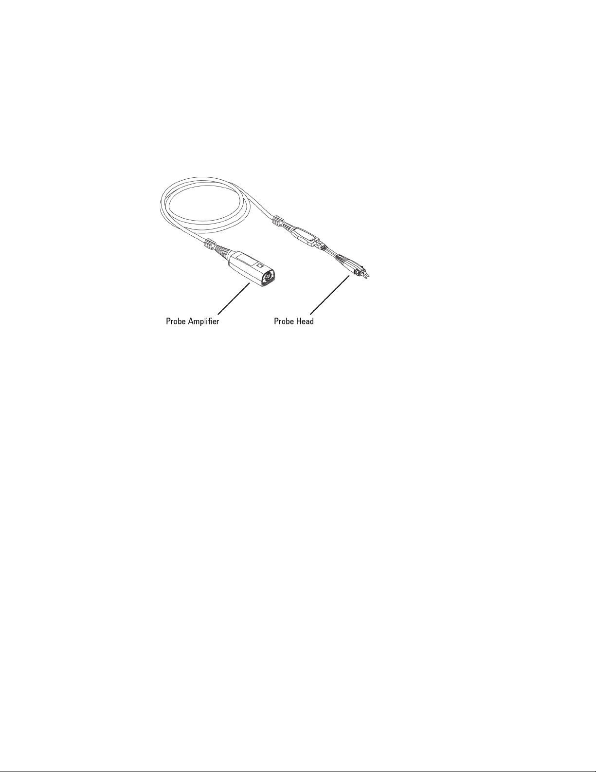
Before you can use the probe, you must connect one of the available probe heads
to an 1168/9B probe amplifier.
Figure 1 Probe Amplifier with Attached Head
Probe Heads
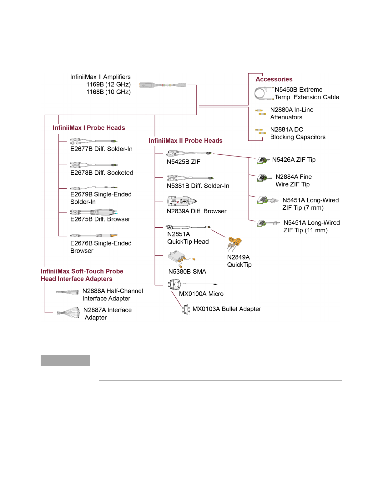
Figure 2 on page 9 shows the available probe heads and accessories. Six different
InfiniiMax II probe heads can be used including a Zero Insertion Force (ZIF) probe
head that uses a ZIF tip that can be installed at many locations on your DUT. The
ZIF tip’s small size is critical in probing tight locations and the ZIF feature allows
connection without compressing the delicate wires which cannot support this
compression. You can also use the probe amplifiers with the InfiniiMax I probe
heads (with some limitations).
The differential probe heads offer easy measurement of differential signals and
greatly improve the measurement of single-ended signals.
Each available probe head is documented in Chapter 2, “Using Probe Heads".
Compatible Oscilloscopes
Table 1 on page 10 lists the oscilloscopes that are compatible with the 1168/9B
probes. Is Your Oscilloscope Software Up-to-Date? Keysight periodically releases
Oscilloscope software updates to support your probe, fix known defects, and
incorporate product enhancements. To download the latest firmware, go to
www.keysight.com and search for your oscilloscope’s topic. Click on the “Drivers,
Firmware & Software” tab.
8 1168/9B Probes User’s Guide
Page 9
Getting Started 1
NOTE
Figure 2 Available Probe Heads and Accessories
N2849A QuickTips are also compatible with the N2848A InfiniiMode probe heads which are
designed for N2830/1/2A and N7000/1/2/3A InfiniiMax III+ and N2800/1/2/3A InfiniiMax III
probes.
These probes can also be used with other test instruments that have 50 ohm input
such as a spectrum analyzer or 86100D DCA. For more information, check out the
Keysight application note, 5989-1869EN.
1168/9B Probes User’s Guide 9
Page 10
1 Getting Started
NOTE
Table 1 Compatible Infiniium Oscilloscopes
Oscilloscope Model
S Series all
V, 90000 X-, Q-, and Z-Series
90000A Series all
86100C/D Series
80000B Series all
a N5442A adapter required.
b N1022A/B adapter required.
b
a
all
all
The 1168/69A InfiniiMax probes are not compatible with Keysight's InfiniiVision Series
oscilloscopes.
Cleaning the probe
If the probe requires cleaning, disconnect it from the oscilloscope and clean it with
a soft cloth dampened with a mild soap and water solution. Make sure the probe is
completely dry before reconnecting it to the oscilloscope.
Channel Identification Rings
When multiple probes are connected to the oscilloscope, use the channel
identification rings to associate the channel inputs with each probe. Place one
colored ring near the probe’s channel connector and place an identical color ring
near the probe head.
Inspecting the Probe
• Inspect the shipping container for damage.
Keep the damaged shipping container or cushioning material until the contents of the
shipment have been checked for completeness and the probe has been checked
mechanically and electrically.
• Check the accessories.
• If the contents are incomplete or damaged, notify your Keysight Technologies
Sales Office.
• Inspect the probe. If there is mechanical damage or defect, or if the probe does
not operate properly or pass calibration tests, notify your Keysight Technologies
Sales Office.
10 1168/9B Probes User’s Guide
Page 11

Getting Started 1
If the shipping container is damaged, or the cushioning materials show signs of
stress, notify the carrier as well as your Keysight Technologies Sales Office. Keep
the shipping materials for the carrier’s inspection. The Keysight Technologies
office will arrange for repair or replacement at Keysight Technologies’ option
without waiting for claim settlement.
Figure 3 shows the accessories that are shipped with the 1168/9B probe
amplifiers. The probe amplifiers do not come with a probe head unless selected at
the time of order. Any head shown in Figure 2 on page 9 can be ordered at any
time for the probes.
Figure 3 Accessories Supplied With the Probe Amplifier
1168/9B Probes User’s Guide 11
Page 12
1 Getting Started
CAUTION
Probe Handling
This probe has been designed to withstand a moderate amount of physical and
electrical stress. However, with an active probe, the technologies necessary to
achieve high performance do not allow the probe to be unbreakable. Treat the
probe with care. It can be damaged if excessive force is applied to the probe tip.
This damage is considered to be abuse and will void the warranty when verified by
Keysight Technologies service professionals.
• Exercise care to prevent the probe end from receiving mechanical shock.
• Store the probe in a shock-resistant case such as the foam-lined shipping case
which came with the probe.
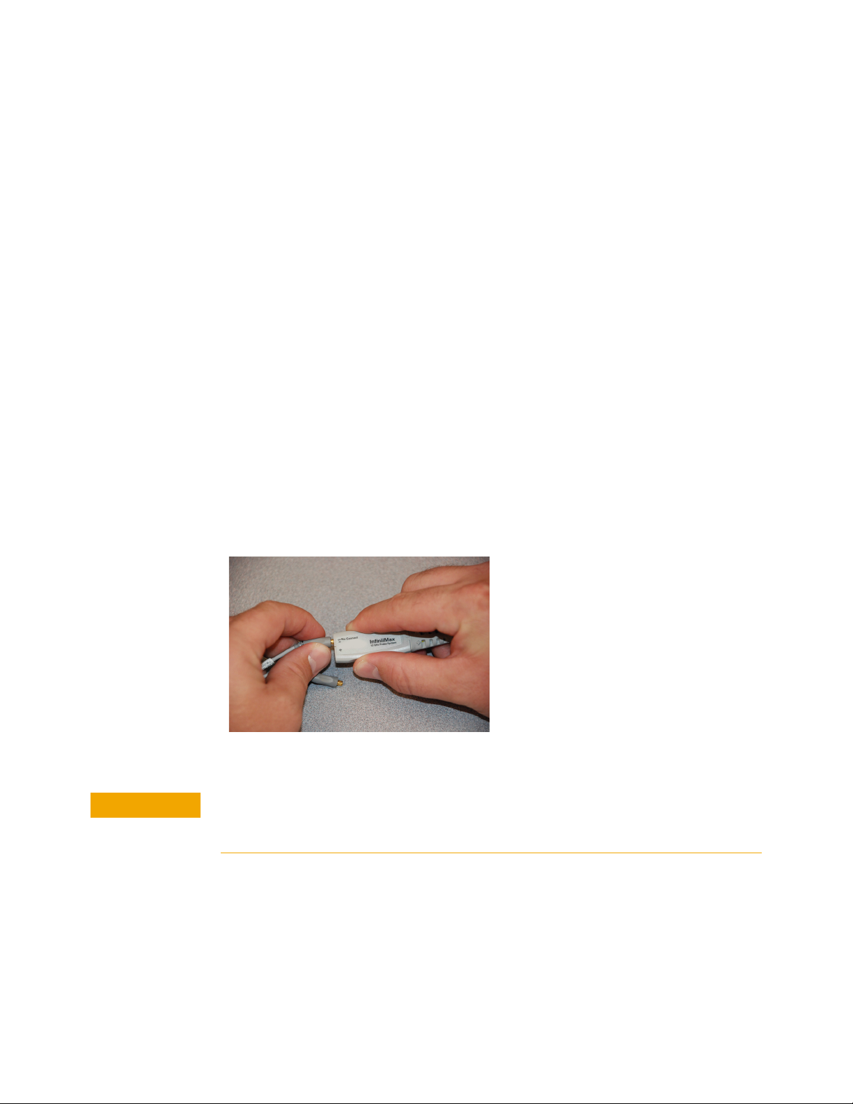
Connecting and Disconnecting Probe Heads
When disconnecting a probe head from an amplifier, pull the probe head
connectors straight out of the sockets as shown in Figure 4. When connecting a
probe head to an amplifier, push straight in. Always grasp the indentations located
on the sides of the amplifier as shown in Figure 4. There are also indentations on
many of the probe head sockets so you have a convenient place to grasp there as
well.
Figure 4 Properly Pulling the Probe Head Straight Out
Avoid damaging the connection pins. Never bend the probe head in order to “pop” it
loose from the amplifier. Do not wiggle the probe head up and down or twist it to
remove the connectors from the sockets.
12 1168/9B Probes User’s Guide
Page 13

Figure 5 Improperly Disconnecting a Probe Head From an Amplifier
CAUTION
CAUTION
Handling the Probe Cable
Getting Started 1
Avoid degrading the probe’s performance. Do not twist, kink, or tightly bend the
probe’s cable.
When the probe is attached to an oscilloscope, avoid letting object hit the probe cable
where the cable exits the probe amplifier and bend it well beyond its limit.
When storing the probe, coil the cable in a large loops and avoid twisting the
cable. Coil the cable in a similar manner to how garden hoses or extension cords
are typically coiled. You can start by wrapping the cable around your thumb as
shown in Figure 6. Then continue to circle your thumb, but provide a slight twist
with each rotation. This allows the cable rotations to lie flat against each other and
will eliminate the net twisting of the cable in the end.
Figure 6 Recommended Coil for Storage
1168/9B Probes User’s Guide 13
Page 14
1 Getting Started
CAUTION
NOTE
Handling the Probe Amplifier
Connecting the Probe to an Oscilloscope
Make the coil’s radius fairly large so it does not induce kinking or bending.
The probe amplifier contains a delicate circuit board. Treat it carefully and take
standard precautions (for example, not dropping it repeatedly or from large
heights, not getting it wet, not smashing it with heavy objects, etc.). These probes
are sensitive ESD devices so standard precautions need to be used to not ruin the
probe from the build-up of static charges.
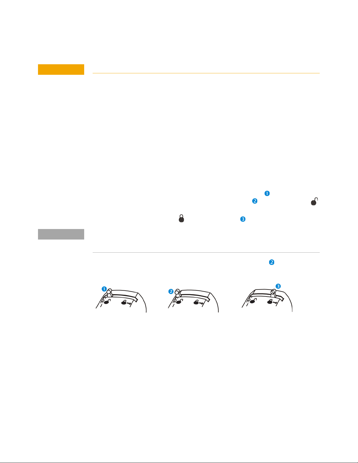
The probes are only meant to be plugged into gold plated BNCs (like those on
Infiniium oscilloscopes). To connect the probe to the oscilloscope, do the following
steps:
1 As shown in Figure 7, with the lever in the relaxed position push the probe
onto the BNC. The lever moves towards the R (release) and returns to the
symbol.
2 Move the lever towards the symbol until snug.
How far the locking mechanism can be pushed to the right varies and will not be the same for
every user. Therefore, do not try to force it further to the right because you believe it is
unlocked. Instead, gently push it until it is snug.
To disconnect the probe, move and hold the lever at R (release) and pull the
probe from the BNC.
Figure 7 Properly Connecting a Probe to the Oscilloscope
Securing Probe Heads and Amplifiers to Your DUTs
When soldering a probe head to a circuit, first provide strain relief by using low
temperature hot glue (use as little as possible) or non-conductive double-sided
tape. Do not use super glue and do not get the low temperature hot glue on the
actual probe head tip as this can damage the precision components of your
probing system (only use the low temperature hot glue on the probe head cables).
The provided velcro pads can be used to secure your probe amplifier casing to the
board.
Once strain relief has been provided, solder the probe tip to the circuit board and
then plug the probe head into the probe amplifier.
14 1168/9B Probes User’s Guide
Page 15
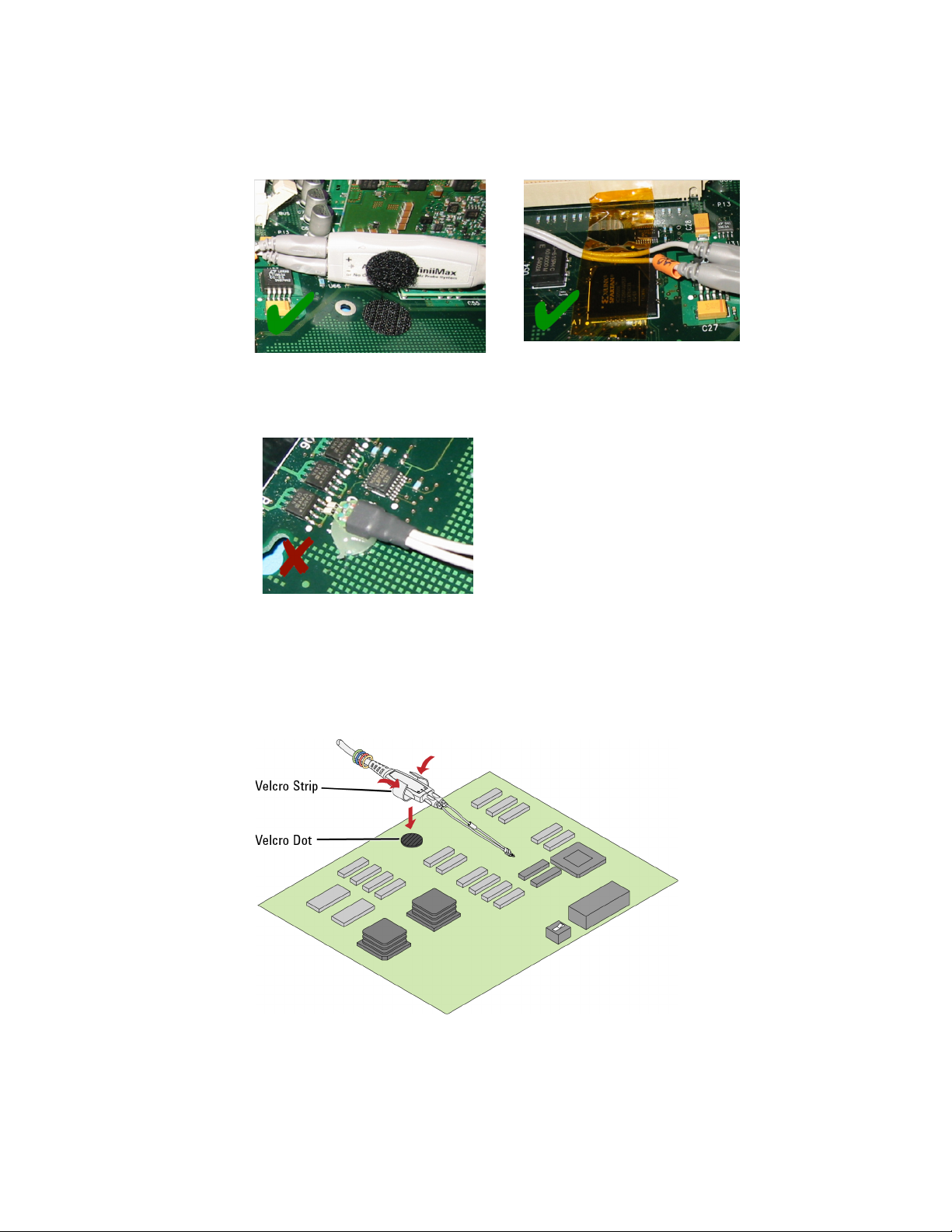
Figure 8 Correct Securing Methods
Getting Started 1
Figure 9 Incorrect Securing Method Because Glue is Placed on the Probe Head Tip
The velcro dots can be used to secure the probe amplifier to a circuit board
removing the weight of the probe from the circuit connection. Attach a Velcro dots
to both the probe amplifier and the circuit board as shown in Figure 10.
Figure 10 Using the Velcro Dots
1168/9B Probes User’s Guide 15
Page 16

1 Getting Started
Using Offset With InfiniiMax Active Probes
It is important to understand how the 1168/9B InfiniiMax probes behave with
respect to offset when different probe head / signal combinations are used.
The purpose of offset in active probes or oscilloscope front ends is to allow the
subtraction of most or all of the dc component of the input signal so the signal can
better utilize the dynamic range of the input. When using an InfiniiMax probe with
an Infiniium oscilloscope, you can select the case (see the three cases described
below) that applies for your measurement by selecting the Probes button under the
channel setup menu. This allows you to select which type of probe head is being
used and, if it is a differential probe head, allows you to select whether you are
probing a differential or single-ended signal. With these inputs, the oscilloscope
will use the proper type of offset for your measurement case. The specifics for each
case are discussed below.
When adjusting the offset for a particular probe head, make sure to have a
triggered signal.
Case 1. A single-ended probe head probing a single-ended signal
For this case, the offset control on the oscilloscope controls the probe offset and
the channel offset is set to zero. This allows the offset voltage to be subtracted
from the input signal before the signal gets to the differential amplifier. Since this
subtraction is done before any active circuits, the offset range is large (±16V). Note
that the minus probe tip is not present when using a single-ended probe head
which means nothing is plugged into the "–" input of the probe amp. This is normal
and causes no problems.
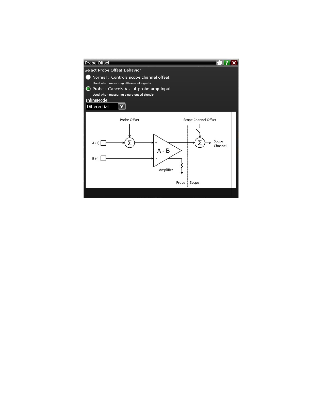
Case 2. A differential probe head probing a single-ended signal
For this case, the offset control on the oscilloscope controls the probe offset and
the channel offset is set to zero. This allows the offset voltage to be subtracted
from the input signal before the signal gets to the differential amplifier. Since this
subtraction is done before any active circuits, the offset range is large (±16V). A
differential probe can make higher bandwidth and more accurate measurements
on single-ended signals than a single-ended probe and this method of applying
offset to only the plus side of a differential probe means there is no sacrificing of
offset range.
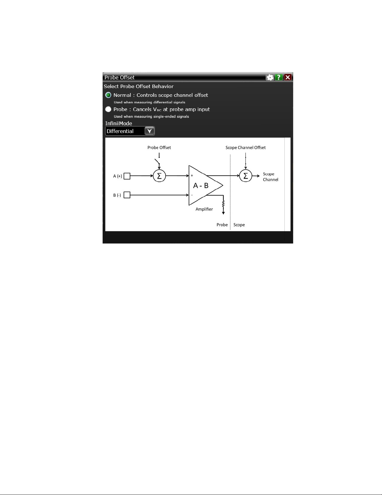
When Probe is selected in the Probe Offset dialog box as shown in Figure 11 on
page 17, the InfiniiMax probe provides a very large offset range (up to ±16V) for
probing single-ended signals and a large common-mode range for probing
differential signals. For information on properly using probe offset to ensure that
you can get the maximum performance and dynamic range from the InfiniiMax
probe, refer to Keysight application note 5988-9264EN.
16 1168/9B Probes User’s Guide
Page 17
Getting Started 1
Figure 11 Probe Offset Dialog Box (Probe Setting)
Case 3. A differential probe head probing a differential signal
For this case, the offset control on the oscilloscope controls the oscilloscope
channel offset. The probe offset is not used and set to zero. Since the plus and
minus sides of differential signals have the same dc component, it will be
subtracted out and the output of the probe will by definition be centered around
ground.
The channel offset allows the waveform seen on screen to be moved as desired.
The allowable dc component in the plus and minus signals is determined by the
common mode range of the probe.
Figure 12 shows Normal selected in the Probe Offset dialog box. When probing
differential signals Normal allows you to apply probe offset using the oscilloscope’s
front-panel vertical offset controls.
1168/9B Probes User’s Guide 17
Page 18
1 Getting Started
Figure 12 Probe Offset Dialog Box (Normal Setting)
18 1168/9B Probes User’s Guide
Page 19
Slew Rate Requirements for Different Technologies
The following table shows the slew rates for several different technologies. The
maximum allowed input slew rate is 25 V/ns for single-ended signals and 40 V/ns
for differential signals. Table 2 shows that the maximum required slew rate for the
different technologies is much less that of the probe.
Table 2 Slew Rate Requirements
Getting Started 1
Max
Single-Ended
Differential
Name of Technology
PCI Express (3GIO) YES 9.6 19.2 50 1.6
RapidIO Serial 3.125Gb YES 8.0 16.0 60 1.6
10GbE XAUI (4x3.125Gb) YES 8.0 16.0 60 1.6
1394b YES 8.0 16.0 60 1.6
Fibre Channel 2125 YES 8.0 16.0 75 1
Gigabit Ethernet 1000Base-CX YES 7.8 15.5 85 2.2
RapidIO 8/16 2Gb YES 7.2 14.4 50 1.2
Infiniband 2.5Gb YES 4.8 9.6 100 1.6
HyperTransport 1.6Gb YES 4.0 8.0 113 1.5
SATA (1.5Gb) YES 1.3 2.7 134 0.6
USB 2.0 YES 0.9 1.8 375 1.1
DDR 200/266/333 NO 7.2 n/a 300 3.6
PCI NO 4.3 n/a 500 3.6
Signal
Slew Rate
(V/ns)
a
Max
Differential
Slew Rate
(V/ns)
Driver Min Edge
b
Rate (20%-80%
ps)
Max Transmitter
Level (Diff V)
AGP-8X NO 3.1 n/a 137 0.7
a The probe specification is 25 V/ns
b The probe specification is 40 V/ns
1168/9B Probes User’s Guide 19
Page 20
1 Getting Started
Available Accessories
This section lists the kits and accessories that are available in addition to the
individual probe heads described in Chapter 2, “Using Probe Heads".
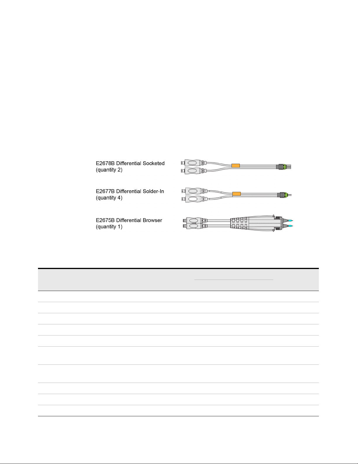
E2669B Differential Connectivity Kit and Accessories
The optional E2669B differential connectivity kit provides multiple quantities of the
three InfiniiMax I probe heads as shown in Figure 13. These probe heads allow full
bandwidth probing of differential and single-ended signals. The kit can be ordered
at the same time as 1168/9B probe amplifiers.
Figure 13 E2669B Differential Connectivity Kit (not to scale)
Table 3 Supplied Accessories (Sheet 1 of 2)
Qty
Description
E2678B Differential Socketed Head 2 — — — —
E2677B Differential Solder-In Head 4 — — — —
E2675B Differential Browser 1 — — — —
160W damped wire accessory 12
82W resistor for full bandwidth 96
Socket for 25 mil (25/1000 inch) square pins, female on
both ends
25 mil female socket with 20 mil round male pin on other
end
Heat shrink socket accessory 8
Header adapter, 91W 4
Supplied
8
8
Used With
E2678B E2677B E2675B
✓
✓
✓
✓
✓
✓
Part
Number
01130-21303
01130-81506
01131-85201
01131-85202
01130-41101
01130-63201
a
82W resistor template 1
20 1168/9B Probes User’s Guide
✓
01131-94309
Page 21

Table 3 Supplied Accessories (Sheet 2 of 2)
Getting Started 1
Qty
Description
91W resistor for full bandwidth 80
150W resistor for medium bandwidth 40
91W resistor template 1
150W resistor template 1
Resistive tip (blue), 91W 20
Ergonomic handle 1
Supplied
a Not orderable.
N2833A InfiniiMax II Differential Connectivity Kit and Accessories
The optional N2833A differential connectivity kit provides multiple quantities of
the four InfiniiMax II probe heads as shown in Figure 14. These probe heads allow
full bandwidth probing of differential and single-ended signals. You can order this
kit either at the same time as 1168/9B probe amplifiers or separately later.
Used With
E2678B E2677B E2675B
✓
✓
✓
✓
✓
✓
Part
Number
0700-2353
0700-2350
01131-94311
01131-94308
01131-62107
01131-43201
a
Figure 14 Probe Heads Included in the N2833A Differential Connectivity Kit (not to scale)
1168/9B Probes User’s Guide 21
Page 22
1 Getting Started
Table 4 Supplied Accessories
Qty
Description
N5381B InfiniiMax II 12 GHz Differential Solder-In Probe Head 2 N5381B
0.007 inch tin-plated nickel wire
0.005 inch tin-plated nickel wire
Trim Gauge
N5425B InfiniiMax II 12 GHz Differential ZIF Solder-in Probe
Head
N5426A InfiniiMax 12 GHz ZIF Tip Kit 2 kits (10 tips in
N2851A InfiniiMax II QuickTip Probe Head 2 N2851A
N2849A InfiniiMax QuickTip Tips Kit 2 kits (4 tips in
N2839A InfiniiMax II Browser Probe Head 1 N2839A
Spring-loaded tips
Tweezer for replacing tips
Protective end cap
* - Indicates the part number of an accessory not orderable separately as an individual product.
Supplied
1
1
1
2 N5425B
each kit)
each kit)
20
1
1
Part
Number
01169-81301 *
01169-21306 *
-
N5426A
N2849A
-
-
-
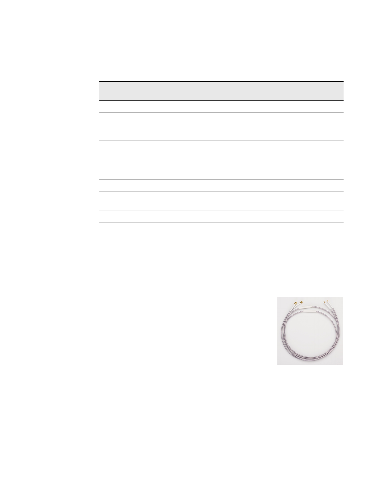
N5450B Extreme Temp Cable Extension Kit
The extreme temperature cable extension kit is an
accessory that allows an oscilloscope probe to be used to
monitor a device in a temperature chamber. Keysight’s
Infiniimax probe amplifiers have a specified operating
temperature range from 5
can be operated over a much larger range of temperatures.
Use the extension cables to physically separate the
amplifier from the probe head which allows you to operate
the probe head inside a temperature chamber while the
probe amplifier remains outside the chamber. To ensure a high-quality
measurement, the N5450B cable set have been phase-matched at the factory. A
coupling tag is included with the cables to ensure the cables stay as a matched
pair. To install the coupling tag, slip the small end of each cable through the holes
in the tag. The tag can be positioned anywhere along the length of the cable and
can withstand the temperature ranges specified.
o
C to 40o C, but the probe heads
22 1168/9B Probes User’s Guide
Page 23

Table 5 Probing Temperature Ranges
CAUTION
CAUTION
CAUTION
CAUTION
CAUTION
NOTE
NOTE
Getting Started 1
Probe Head
Configuration
N5381B –40° to +85° > 250
E2677B –25° to +80° > 1000
E2678B –25° to +80° > 1000
N5425B + N5426A -40° to +85° > 500
N5451A –25° to +80° > 1000
MX0100A -55° C dwell, 1000 hours minimum
a Refers to the probe head or tip that is attached to the cable extension kit.
a
Operating Temperature Range (oC)
+150° C dwell, 1000 hours minimum
-55° C to 150° C cycles, 1000 cycles minimum
(as per JEDEC JESD22-A104 revision E)
Expected Lifetime of
the Probe Head (cycles)
> 1000
Avoid rapid changes in temperature that can lead to moisture accumulating in the
form of condensation on the probe components, as well as the DUT. If this occurs, wait
until the moisture has evaporated before making any measurements.
Additional care must be taken when handling probe heads used during extreme
temperature cycling because this process makes the probe heads less robust.
Secure the ends of the extension cable near the probe head in the temperature
chamber such that the probe head legs are not tugged or moved around significantly.
Prevent abrasion and tears in the cable’s jacket, do not rest the extension cables on
any metal objects or objects with sharp edges.
Do not kink the cables. The cables are designed to be flexible, but are not designed to
be bent sharply.
Keep your extreme temperature testing probes separate from the probes they use under
milder conditions. This is because cycling probe heads through extreme temperature ranges
has a marked affect on their lifetimes as listed in Table 5. Only the lifetime of the probe head
is affected by temperature cycling. The extension cables and probe amplifier should not need
to be replaced with extended temperature cycling.
Discoloration or texture changes are possible with the extension cables. These changes do
not, however, affect the performance or the quality of a measurement.
1168/9B Probes User’s Guide 23
Page 24
1 Getting Started
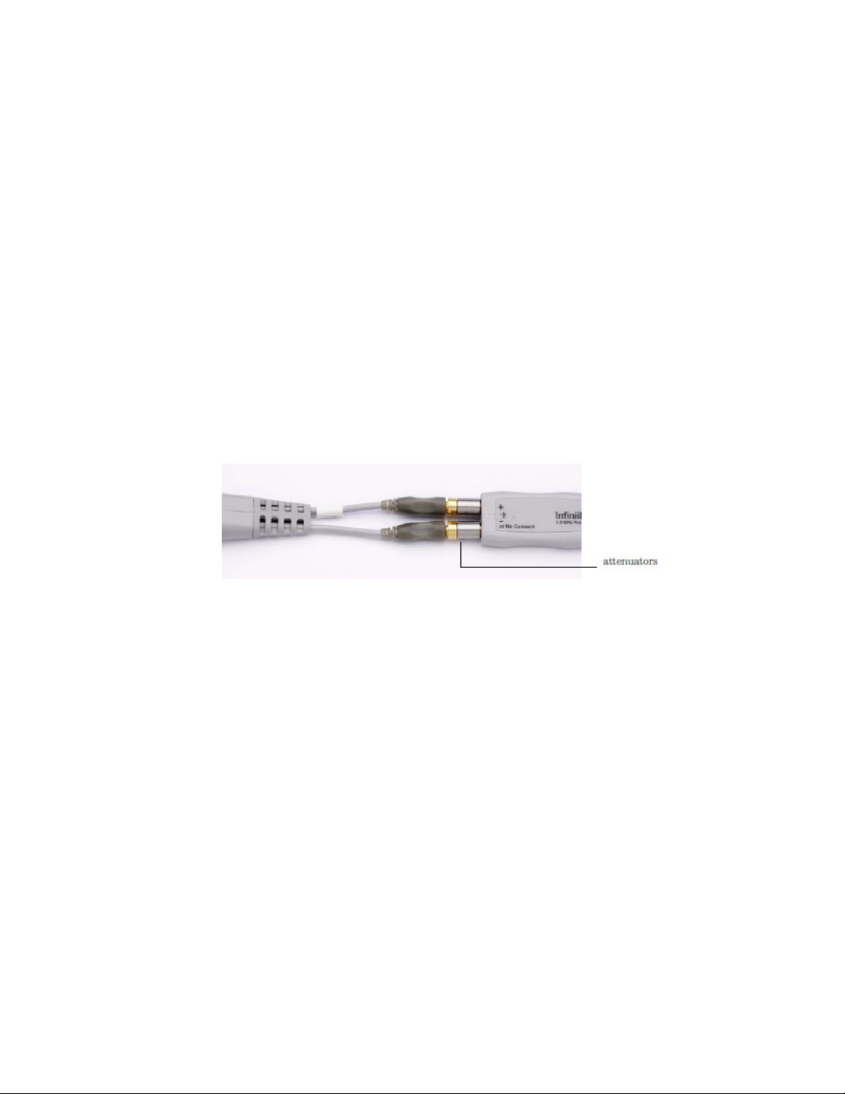
N2880A InfiniiMax In-Line Attenuator Kit
The in-line attenuators are an accessory for probes. The maximum input range of
the 1168B/9B probes are 3.3 V
. If you need to measure larger signals, the
p-p
probe’s design allows you to add the N2880A InfiniiMax in-line attenuators
between the probe head and probe amplifier to increase the maximum input range
(as listed in Table 6 on page 25). Additionally, these attenuators enable you to
increase the offset range of the probe as specified in Table 6 on page 25. When
using the N2880A In-Line Attenuators, the bandwidth and rise time of your
probing system is not affected. There is, however, a trade-off in noise (refer to
Table 6) and in the accuracy of DC offset relative to the input.
The N2880A provides a pair of 6 dB, 12 dB, and 20 dB attenuators. The
attenuators come as matched pairs and should only be used with each other. Each
attenuator has a serial number. The pair of matching attenuators in each set will
have the same four digit numeric prefix and will differ by the last letter (one
attenuator in the matched pair will be labeled A and the other will be labeled B).
Compatibility with probe heads and amplifiers
All InfiniiMax I and II probe heads and amplifiers are compatible with the N2880A
In-line attenuators. However, the following two limitations should be considered
when planning to use N2880A attenuators.
• The maximum input voltage of the InfiniiMax I probe heads is ±30 Vdc and so
they should not be used to measure signals that exceed this range. This places
a practical limit of 20 dB on the attenuators used with the InfiniiMax I probing
system. Larger attenuation ratios will only degrade the noise performance and
gain of the system.
• Due to the N5380B dual-SMA probe head’s maximum input voltage
specification of 2.28 V
large enough to require an added attenuator.
, the N5380B is not suitable for measuring signals
RMS
24 1168/9B Probes User’s Guide
Page 25
.
NOTE
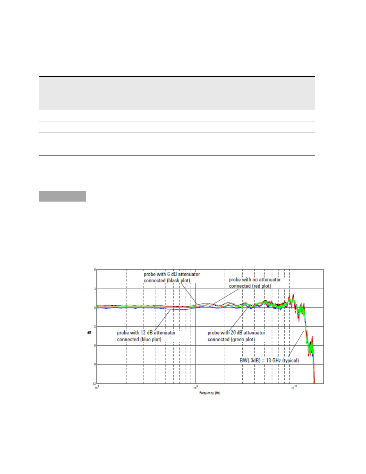
Red = dB(Vout/Vin) + 10.8 dB of probe
Blue = dB (Vout/Vin) + 12 dB attenuator + 10.8 dB of probe
Black = dB(Vout/Vin) + 6dB attenuator + 10.8 dB
Green = dB(Vout/Vin) + 20 dB attenuator + 10.8 dB of probe
Table 6 N2880A With 1168B/9B Probe Amplifiers
Getting Started 1
Added
Attenuator
Maximum Input
Range
(mains isolated
circuits only)
Offset
Range
Typical Noise
Referred to
Maximum Allowed
Input Slew Rate
a
(se = single-ended)
(diff = differential)
Nominal DC
Attenuation of
Probe System
None 3.3 Vp-p ±16V 2.2 mV RMS se: 25 V/ns, diff: 40 V/ns 3.45:1
6 dB (2:1) 6.6 Vp-p ±30 V
12 dB (4:1) 13.2 Vp-p ±30 V
20 dB (10:1) 33.3 Vp-p ±30 V
a These slew rate do not apply when the N5380B SMA probe head is used with the InfiniiMax amplifiers.
b The actual range of DC voltage for N2880A is > ±30 V, but the usable range of DC voltage at the probe input is limited to ±30 Vdc.
b
b
b
6.3 mV RMS se: 50 V/ns, diff: 80 V/ns 6.9:1
13.2 mV RMS se: 100 V/ns, diff: 160 V/ns 13.8:1
33.4 mV RMS se: 250 V/ns, diff: 400 V/ns 34.5:1
The values shown above do not apply to the N5380B dual-SMA probe head. Due to the
maximum input voltage specification of 2.28 VRMS (mains isolated circuits only) for the
N5380B, it is not suitable for measuring signals large enough to require an added attenuator.
Frequency Response Plots
Below are the frequency response plots for four setups: the probe without any
attenuators, the probe with the 6 dB attenuators, the probe with the 12 dB
attenuators, and the probe with the 20 dB attenuators.
Figure 15 Frequency Response
1168/9B Probes User’s Guide 25
Page 26
1 Getting Started
Extended Offset Range with N2880A Attenuators
The use of N2880A attenuators allows an increased offset range (±30 Vdc) of the
probe as listed in Table 6 on page 25.
However, if you are using the12 dB (4:1) or 20 dB (10:1) N2880A attenuators with
the N5381A/B probe head and InfiniiMax II probe amplifier, an extended offset
range (±60 Vdc) is allowed to enable you to measure higher input voltages.
When you connect the appropriate attenuators, probe head, and probe amplifier
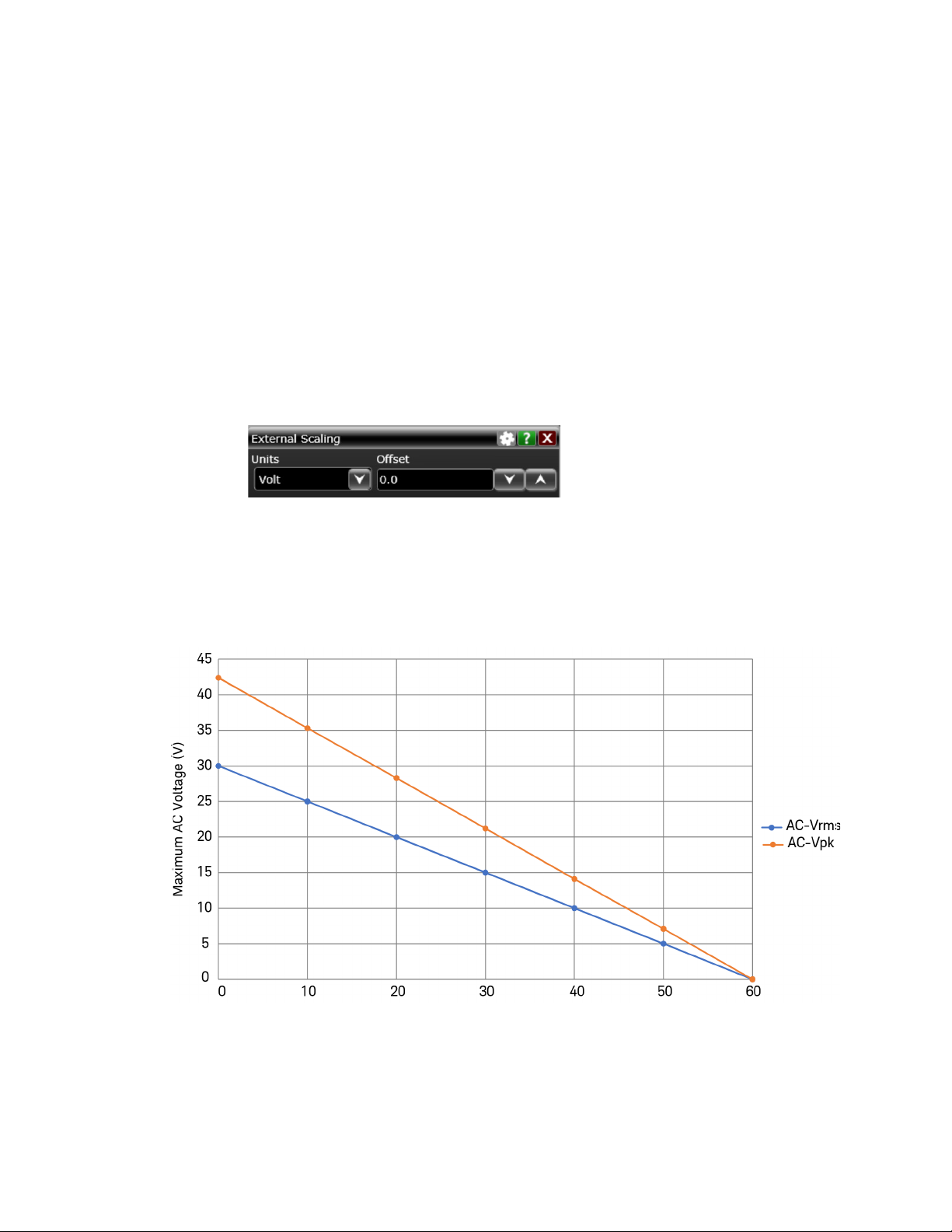
to the oscilloscope, the extended offset range is available using the Offset field of
the External Scaling dialog box in the Infiniium software GUI. You access this dialog
box by clicking Setup > Probe Configuration.... and then enabling External Scaling.
For this extended offset range, the maximum allowed AC voltage is dependent on
the DC voltage on the signal. The graph in Figure 16 depicts the DC voltage and
the corresponding allowed maximum AC voltage for this extended range. It is
recommended that you use the maximum AC voltage values depicted in this graph
to set the extended offset value in the Infiniium GUI.
Figure 16 Extended offset range - Maximum AC voltage recommendations corresponding to
the DC voltage
You can also calculate the maximum allowed AC voltage using the following
equations.
26 1168/9B Probes User’s Guide
Page 27

Getting Started 1
Maximum V
Maximum V
ACRMS
AC_PEAK
= 30 * (60 - VDC) / 60
= 42.4 * (60 - VDC) / 60
Calibrating and Configuring Attenuators on an Infiniium Series
Oscilloscope
The software in the Infiniium oscilloscopes will detect a probe when it is connected
and by default will assume that no additional attenuators are installed. If you want
to scale readings and settings on the oscilloscope so they are correct with the
attenuators installed, refer to the procedures below for your specific oscilloscope
series.
Calibrating Attenuators on an Infiniium Series Oscilloscope
You cannot calibrate your InfiniiMax probes with the attenuators attached.
Calibrate the InfiniiMax probes as you normally would (with no attenuators),
configure the attenuators as discussed in the next section, and begin probing.
Configuring Attenuators on an Infiniium Series Oscilloscope
First, plug your InfiniiMax probe amplifier / probe head into one of the oscilloscope
channels with the attenuators connected. Then enter the Probe Setup dialog box
(can be reached via Setup > Probes on the oscilloscope menu). Press the Configure
Probing System button. A pop-up window will appear where you can select External
Scaling. Click the Decibel radio button under the External Scaling section and then
set the Gain field to either –6 dB, –12 dB, or –20 dB depending on the attenuator
you are using (be sure to include the negative sign). Finally, you will need to
manually set the Offset field in this dialog box to zero out the signal.
1168/9B Probes User’s Guide 27
Page 28
1 Getting Started
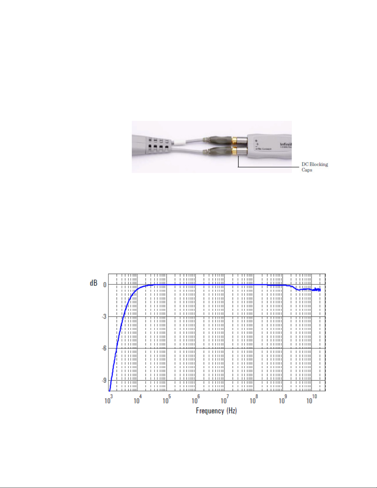
N2881A InfiniiMax DC Blocking Capacitors
The DC blocking capacitors are an accessory for the probes. The architecture of
the InfiniiMax probing system allows you to place the N2881A DC blocking caps in
between the probe amplifier and the probe head as shown in Figure 17. The
capacitors block out the DC component of the input signal (up to 30 Vdc).
Figure 17 Blocking Caps Between Probe Amplifier and Head
You can use the blocking capacitors with the N2880A In-Line Attenuators. The
order of the two products in the probing system (that is, which one is closest to the
probe amplifier) does not matter.
Figure 18 on page 28 shows the frequency response plot of the blocking
capacitors (no probe included).
Figure 18 DC Blocking Cap Insertion Loss (S21) versus Frequency (DC Blocking Cap only)
28 1168/9B Probes User’s Guide
Page 29

MX0102A Soldering Toolkit
Straight
Tweezers
Cutting
Tweezer s
Double-sided Foam Tape
Low Temperature
Solder Wire
Regular Solder Wire
Probe Tip Wire
Kapton
Tap e
The optional MX0102A soldering toolkit provides tools that can make soldering
tasks easier. For instance, you can use the tools available in this kit while soldering
the lead wires of the MX0100A Micro probe head to a DUT (see page 44).
Getting Started 1
Table 7 Accessories supplied in the soldering toolkit
Description
Straight Tweezers
Qty
Supplied
1 8710-2837
(Anti-magnetic straight pointed tip 120mm)
For general purpose manipulation / movement of com-
ponents such as probe tip wires and probe head.
Cutting Tweezers
1 8710-2838
(Narrow oblique head 115mm)
To cut a probe tip wire to a desired length.
Kapton Tape (36 yards roll)
1 0460-3121
To provide strain-relief to the neck portion of the probe
head by taping it to a flat surface (such as a DUT circuit
board).
1168/9B Probes User’s Guide 29
Part
Number
a
Page 30
1 Getting Started
Description
Double-sided Foam Tape
To provide strain-relief to either the neck portion of the
probe head or the plastic housings by taping it to a flat
surface such as a tabletop or a DUT circuit board.
Regular Solder Wire
Lead free, .009" diameter, 2 feet long
To attach the probe tip wires to a DUT using standard
lead-free soldering temperatures (330 °C to 350 °C).
(NOTE: This alloy melts at 217
o
C.)
Low Temperature Solder Wire
Lead free, .010" diameter, 2 feet long
To attach the probe tip wires to a DUT using a low tem-
perature setting on your soldering iron.
(NOTE: This alloy melts at 138
o
C.)
Probe Tip Wire
.004" diameter, 2 feet long
To add ground wires to your probe tip if InfiniiMode mea-
surements (differential, single ended, and common
mode signals with a single probe tip) are desired. Clip as
short as possible using the cutting tweezers included in
the kit.
Qty
Supplied
Part
Number
a
10 0460-3122
1 MX0102-21302
1 MX0102-21303
1 MX0102-21301
a You can reorder these items using the part numbers included in the table above.
30 1168/9B Probes User’s Guide
Page 31

Safety Information
WARNING
WARNING
WARNING
WARNING
WARNING
WARNING
This manual provides information and warnings essential for operating this probe
in a safe manner and for maintaining it in safe operating condition. Before using
this equipment and to ensure safe operation and to obtain maximum performance
from the probe, carefully read and observe the following warnings, cautions, and
notes.
This product has been designed and tested in accordance with accepted industry
standards, and has been supplied in a safe condition. The documentation contains
information and warnings that must be followed by the user to ensure safe
operation and to maintain the product in a safe condition.
Note the external markings on the probe that are described in this document.
To avoid personal injury and to prevent fire or damage to this product or products
connected to it, review and comply with the following safety precautions.
Use Only Grounded Instruments. Do not connect the probe’s ground lead to a
potential other than earth ground. Always make sure the probe and the oscilloscope
are grounded properly.
Getting Started 1
Connect and Disconnect Properly. Connect the probe to the oscilloscope and
connect the ground lead to earth ground before connecting the probe to the circuit
under test. Disconnect the probe input and the probe ground lead from the circuit
under test before disconnecting the probe from the oscilloscope.
Observe Probe Ratings. Do not apply any electrical potential to the probe input which
exceeds the maximum rating of the probe. Make sure to comply with the voltage
versus frequency derating curve found in this manual.
These Probe assemblies are not intended for measurements on mains circuits (CAT
II, CAT III, and CAT IV).
Indoor Use Only. Do not operate in wet/damp environments. Keep product surfaces
dry and clean.
Never leave the probe connected to a conductor while it is not connected to an
oscilloscope or voltage measuring instrument.
Periodically inspect the probe and probe wires to check for any damage. Do Not
Operate With Visible or Suspected Failures. If you suspect there is damage, have it
inspected by a Keysight authorized service personnel.
1168/9B Probes User’s Guide 31
Page 32

1 Getting Started
WARNING
WARNING
WARNING
WARNING
CAUTION
WARNING
WARNING
WARNING
WARNING
Do not install substitute parts or perform any unauthorized modification to the
probe.
Do not operate the probe or oscilloscope in the presence of flammable gasses or
fumes. Operation of any electrical instrument in such an environment constitutes a
definite safety hazard.
If the probe is used in a manner not specified by the manufacturer, the protection
provided by the probe assembly may be impaired.
Do not attempt internal service or adjustment. Service should be carried out by a
Keysight Technologies authorized service personnel. For any service needs, contact
Keysight Technologies.
The probe cable is a sensitive part of the probe and, therefore, you should be careful
not to damage it through excessive bending or pulling. Avoid any mechanical shocks
to this product in order to guarantee accurate performance and protection.
Concerning the Oscilloscope or Voltage Measuring Instrument to Which
the Probe is Connected
Whenever it is likely that the ground protection is impaired, you must make the
instrument inoperative and secure it against any unintended operation.
If you energize the instrument by an auto transformer (for voltage reduction or
mains isolation), the ground pin of the input connector terminal must be connected
to the earth terminal of the power source.
Before turning on the instrument, you must connect the protective earth terminal of
the instrument to the protective conductor of the (mains) power cord. The mains
plug shall only be inserted in a socket outlet provided with a protective earth
contact. You must not negate the protective action by using an extension cord
(power cable) without a protective conductor (grounding). Grounding one conductor
of a two-conductor outlet is not sufficient protection.
Capacitors inside the instrument may retain a charge even if the instrument is
disconnected from its source of supply.
32 1168/9B Probes User’s Guide
Page 33

Troubleshooting
The following symptoms may indicate a problem with the probe or the way it is
used. The probe is a high frequency device with many critical relationships
between parts. For example, the frequency response of the amplifier on the hybrid
is trimmed to match the output coaxial cable. As a result, to return the probe to
optimum performance requires factory repair. If the probe is under warranty,
normal warranty services apply.
Probe Calibration Fails
Probe calibration failure with an oscilloscope is usually caused by improper setup.
If the calibration will not pass, check the following:
• Check that the probe passes a waveform with the correct amplitude.
• If the probe is powered by the oscilloscope, check that the offset is
approximately correct. The probe calibration cannot correct major failures.
• Be sure the oscilloscope passes calibration without the probe.
Getting Started 1
• Be sure that the probe head that you are using has been in the oscilloscope’s
Probe Setup dialog box.
Incorrect Pulse Response (flatness)
If the probe's pulse response shows a top that is not flat, check for the following:
• Output of probe must be terminated into a proper 50W termination. If you are
using the probe with an Infiniium oscilloscope, this should not be a problem. If
you are using the probe with other test gear, ensure the probe is terminated
into a low reflectivity 50W load (~ ±2%).
• If the coax or coaxes of the probe head in use has excessive damage, then
reflections may be seen within approximately 1 ns of the input edge. If you
suspect a probe head, swap it with another probe head and see if the
non-flatness problem is fixed.
• If the one of the components in the tip have been damaged there may be a
frequency gain non-flatness at around 40 MHz. If you suspect a probe head,
swap it with another probe head and see if the non-flatness problem is fixed.
Incorrect Input Resistance
The input resistance is determined by the probe head in use. If the probe head is
defective, damaged, or has been exposed to excessive voltage, the input resistor
may be damaged. If this is the case, the probe head is no longer useful. A new
probe head will need to be obtained either through purchase or warranty return.
1168/9B Probes User’s Guide 33
Page 34

1 Getting Started
NOTE
NOTE
Incorrect Offset
Returning the Probe for Service
Assuming the probe head in use is properly functioning, incorrect offset may be
caused by defect or damage to the probe amplifier or by lack of probe calibration
with the oscilloscope.
If the probe is found to be defective we recommend sending it to an authorized
service center for all repair and calibration needs. Perform the following steps
before shipping the probe back to Keysight Technologies for service.
1 Contact your nearest Keysight sales office for information on obtaining an RMA
number and return address.
2 Write the following information on a tag and attach it to the malfunctioning
equipment.
• Name and address of owner
• Product model number (for example, 1168B)
• Product Serial Number (for example, MYXXXXXXXX)
• Description of failure or service required
Include probing and browsing heads if you feel the probe is not meeting performance
specifications or a yearly calibration is requested.
3 Protect the probe by wrapping in plastic or heavy paper.
4 Pack the probe in the original carrying case or if not available use bubble wrap
or packing peanuts.
5 Place securely in sealed shipping container and mark container as "FRAGILE".
If any correspondence is required, refer to the product by serial number and model number.
34 1168/9B Probes User’s Guide
Page 35

Contacting Keysight Technologies
For technical assistance, contact your local Keysight Call Center.
• In the Americas, call 1 (800) 829-4444
• In other regions, visit http://www.keysight.com/find/assist
Before returning an instrument for service, you must first call the Call Center at 1
(800) 829-4444.
Getting Started 1
1168/9B Probes User’s Guide 35
Page 36

1 Getting Started
36 1168/9B Probes User’s Guide
Page 37

Keysight InfiniiMax II Series Probes
User’s Guide
2 Using Probe Heads
Recommended Configurations 38
1. MX0100A InfiniiMax Micro Probe Head 41
2. N5381B Differential Solder-In 50
3. N2839A Differential Browser 52
4. N5382A Differential Browser 57
5. N5380B SMA 60
6. N5425B with N5426A ZIF Tip 63
7. N5425B with N2884A Fine Wire ZIF Tip 64
8. N2851A QuickTip Probe Head 67
9. N5425B with N5451A Long-Wire ZIF Tip (7 mm) 71
10. N5425B with N5451A Long-Wire ZIF Tip (11 mm) 73
11. E2677B Differential Solder-In Probe Head 75
12. E2678B Differential Socketed Probe Head 77
13. E2675B Differential Browser 79
14. E2679B Single-Ended Solder-in Probe Head 81
15. E2676B Single-Ended Browser 82
16. E2678B Differential Socketed & Damped Wire Accessory 84
Soldering a ZIF Tip to a DUT 86
Using N2884A Fine-Wire ZIF tips 90
N2887A/8A Soft Touch Probe Heads 98
Performance graphs showing the performance of the heads are shown in
Chapter 6. This chapter describes the probe head configurations listed in the order
of the best performance to the least performance. Always refer to the information
in this chapter before using any probe head. The recommended configurations are
designed to give the best probe performance for different probing situations. This
allows you to quickly make the measurements you need with confidence in the
performance and signal fidelity.
37
Page 38

2 Using Probe Heads
Recommended Configurations
Table 8 Recommended InfiniiMax II Configurations (Sheet 1 of 2)
Recommended
Order of Use
MX0100A InfiniiMax Micro Probe Head (Refer to page 41.)
1 Full Bandwidth
N5381B Differential Solder-In (Refer to page 50.)
2 Full Bandwidth
N2839A Differential Browser (Refer to page 52.)
3 Full Bandwidth
BW (GHz)
1168B: 10
1169B: 12
1168B: 10
1169B: 12
1168B: 10
1169B: 12
Cdiff a
(pF)
0.17 0.26 Differential and Single-ended signals
0.21 0.35 Differential and Single-ended signals
0.21 0.34 Differential and Single-ended signals
b
Cse
(pF) Usage
Lowest input loading
Pre-wired micro solder-in probe head kit
Light, flexible, small, and reusable
Designed to access small geometry target devices
Solder-in hands free connection
Hard to reach targets
Very small fine pitch targets
Characterization
Hand-held browsing
Adjustable tip spacing
General purpose troubleshooting
Compatible with N2784/5A or N2787A probe positioners
N5382A Differential Browser (Refer to page 57.)
4 Full Bandwidth
1168B: 10
1169B: 12
N5380B SMA (Refer to page 60.)
5 Full Bandwidth
1168B: 10
1169B: 12
N5425B ZIF with N5426A ZIF Tip (Refer to page 63.)
6 Full Bandwidth
1168B: 10
1169B: 12
38 1168/9B Probes User’s Guide
0.21 0.35 Differential and Single-ended signals
Hand-held browsing
Probe holders
General purpose troubleshooting
Ergonomic handle available
N/A N/A Full bandwidth
Preserve oscilloscope channels as opposed to using the A minus B
mode.
Removes inherent cable loss through compensation.
Common mode termination voltage can be applied
Offset matched sma cables adapt to variable spacing
0.33 0.53 Differential and Single-ended signals
Solder-in with ZIF Tip connection
Very small fine pitch target
Slightly higher loading than solder-in probe head
Page 39

Table 8 Recommended InfiniiMax II Configurations (Sheet 2 of 2)
Using Probe Heads 2
Recommended
Order of Use
BW (GHz)
Cdiff a
(pF)
b
Cse
(pF) Usage
N5425B ZIF with N2884A Fine Wire ZIF Tip (Refer to page 64.)
7 Full Bandwidth
1168B: 10
1169B: 12
0.35 — Differential high fidelity
Solder-in fine wire with ZIF Tip connection
Extremely small fine pitch target, active ICs
Fragile lead wires
N2851A QuickTip Probe Head (Refer to page 67.)
8 Full Bandwidth
1168B: 10
1169B: 12
0.72 0.71 Easy, secure magnetic connection between head and tip.
Use N2848A and N2849A with InfiniiMax III+ amplifier for
InfiniiMode function.
N5425B ZIF with N5451A Long Wired ZIF Tip (7 mm resistor length) (Refer to page 71.)
9 ~9.9 (0° span)
~4.4 (60° span)
c
—0.6
d
0.58
Differential and Single-ended signals
Solder-in with LW ZIF Tip connection
Variable pitch targets, including larger pitches
Higher loading than solder-in probe head
N5425B ZIF with N5451A Long Wired ZIF Tip (11 mm resistor length) (Refer to page 73.)
10 ~5 (0° span)
~3.3 (60° span)
c
d
—0.68
0.68
Differential and Single-ended signals
Solder-in with LW ZIF Tip connection
Variable pitch targets, including larger pitches
Higher loading than solder-in probe head
a Capacitance seen by differential signals
b Capacitance seen by single-ended signals
c 0° span between the two LW ZIF resistor leads
d 60° span between the two LW ZIF resistor leads
Table 9 lists probe head configurations that are available in the E2669B
connectivity kit. Not all of these configurations will give the best probe
performance of the 1168B and 1169B. The probe configurations are shown in the
order of the best performance to the least performance.
1168/9B Probes User’s Guide 39
Page 40

2 Using Probe Heads
Table 9 InfiniiMax I Configurations
Recommended
Order of Use
BW
(GHz)
Cdiff a
(pF)
b
Cse
(pF) Usage
E2677B Differential Solder-In (high bandwidth resistors) (Refer to page 75.)
11 1168B: 10
1169B: 12
0.27 0.44 Differential and Single-ended signals
Solder-in hands free connection
Hard to reach targets
Very small fine pitch targets
Characterization
E2678B Differential Socketed (full bandwidth resistors) (Refer to page 77.)
12 1168B: 10
1169B: 12
0.34 0.56 Differential and Single-ended signals
Removable connection using solder-in resistor pins
Hard to reach targets
E2675B Differential Browser (Refer to page 79.)
13 ~5.2 0.32 0.57 Differential and Single-ended signals
Hand-held browsing
Probe holders
General purpose troubleshooting
Ergonomic handle available
E2679B Single-Ended Solder-In (high bandwidth resistors) (Refer to page 81.)
14 ~5.2 N/A 0.50 Single-ended signals only
Solder-in hands free connection when physical size is critical
Hard to reach targets. Very small fine pitch targets
E2676B Single-Ended Browser (Refer to page 82.)
15 ~6 N/A 0.65 Single-ended signals only
Hand or probe holder where physical size is critical
General purpose troubleshooting
Ergonomic handle available
E2678B Differential Socketed with Damped Wire Accessories (Refer to page 84.)
16 ~1.2 0.63 0.95 Differential and Single-ended signals
For very wide spaced targets
Connection to 25 mil square pins when used with supplied
sockets
a Capacitance seen by differential signals
b Capacitance seen by single-ended signals
40 1168/9B Probes User’s Guide
Page 41

1. MX0100A InfiniiMax Micro Probe Head
MX0100A Probe
Head
MX0103A Bullet
Adapter
InfiniiMax Probe
Amplifier
The MX0100A is a small,
flexible, and lightweight
solder-in probe head that
allows you to conveniently
probe denser and
smaller-sized target devices.
The micro size and flexibility features of this probe head overcome the probing
challenges faced with the smaller pads and narrower spacing in such small
devices..
This probe head configuration supports the highest bandwidth and provides the
full bandwidth signals (1168B: 10 GHz, 1169B: 12 GHz) and the lowest capacitive
loading for measuring both single-ended and differential signals.
This probe head connects easily to an InfiniiMax probe amplifier using the bullet
adapter shipped with the probe head.
Using Probe Heads 2
For connection to a DUT, it has pre-wired probe tip leads that allow solder-in
connection to very small, fine pitch targets.
Figure 19 MX0100A probe head connected to DUT and InfiniiMax probe amplifier
1168/9B Probes User’s Guide 41
Page 42

2 Using Probe Heads
NOTE
CAUTION
Before usage under high
temperatures
Discoloration after usage
under high temperatures
When probing differential signals, the + and – connection of the MX0100A probe head can be
determined when the probe head is plugged into the probe amplifier. The + and - indicators
on the probe amplifier represent the + and - inputs on MX0100A probe head.
When probing single-ended signals, ensure that the - input of the probe amplifier is
connected to the ground of the DUT.
Extreme Temperature Testing with MX0100A Probe Head
The MX0100A probe head can withstand temperatures from –55°C to +150°C
thereby making it suitable for extreme temperature environments such as
temperature chambers. For extreme temperature testing, use the MX0100A probe
head with the N5450B InfiniiMax extreme temperature extension cable.
InfiniiMax probe amplifiers cannot withstand extreme
temperatures (–55°C to +150°C) that the MX0100A probe head
can withstand. Be cautious not to subject these probe amplifiers
to extreme temperatures. Using the N5450B extension cable with
the MX0100A probe head physically separates the amplifier from
the probe head and therefore eliminates the chances of the
amplifier’s exposure to extreme temperatures.
To know more about the N5450B extension cable and cautions associated with
using an InfiniiMax probe head in extreme temperature testing, refer to “N5450B
Extreme Temp Cable Extension Kit" on page 22.
The MX0100A probe head components may undergo discoloration when used
under high temperatures. Such changes do not, however, affect the probe head’s
performance or measurement quality. The probe head maintains its specified
frequency response and bandwidth over the operating temperature range (–55°C
to +150°C), without any need for compensation or correction.
42 1168/9B Probes User’s Guide
Page 43

Using Probe Heads 2
NOTE
NOTE
NOTE
Required Infiniium Software Version
The MX0100A probe head requires the Infiniium software version 6.30 or higher.
MX0100A Probe Head Kit Components
Table 10 MX0100A Probe Head Kit Components
Component Quantity * Part Number
Option 001 Option 002 Option 003
Micro Probe Heads (with pre-wired probe tips) 5 25 50 MX0100A
Probe Tip Wire (.004" diameter)
(To make ground connections)
Bullet Adapter 1 5 10 MX0103A
Trim Gauge Template (see Figure 20) 1 5 10 MX0100-94302
* Quantity varies based on the purchased option.
1 wire spool 5 wire spools 10 wire spools MX0102-21301
For Performance plots, refer to “MX0100A Micro Probe Head (Full BW)" on page 152.
For Spice model, refer to “MX0100A Micro Probe Head" on page 222.
If the probe tip lead wire is damaged or worn out, replace the lead wire using the procedure
“To Replace an MX0100A Probe Tip Lead Wire" on page 106.
To know how to avoid damage to the MX0100A probe head, refer to the topic “MX0100A
Probe Head Handling Precautions" on page 47.
Trimming the Lead Wires of MX0100A Probe Head
Before soldering, trim the probe head’s lead wires matching your DUT’s geometry.
You can choose from the following lead wire lengths:
• 135 mil (3.4 mm) - The probe head is shipped with this factory-trimmed standard
length. Use this lead wire length to accommodate variable-pitch targets. With
this length, you get the maximum convenience in terms of longer reach and the
available bandwidth is the full bandwidth of the probe amplifier being used
(1168B: 10 GHz and 1169B: 12 GHz).
1168/9B Probes User’s Guide 43
Page 44

2 Using Probe Heads
NOTE
NOTE
NOTE
• 60 mil (1.5 mm) - If your DUT’s geometry allows you to use shorter lead wire
length, trim the wires to this length to get the maximum performance. Use this
lead wire length to accommodate small fine-pitch targets. The available
bandwidth is the full bandwidth of the probe amplifier being used (1168B:
10 GHz and 1169B: 12 GHz).
You need to specify your choice of lead wire length (3.4 mm or 1.5 mm) in
the Probe Configuration dialog box of the Infiniium software GUI. This allows
the software to load the appropriate s parameter file applicable to that wire
length. The s parameter file adjusts the frequency response to enhance the
measurements accuracy.
To properly trim the probe head’s lead wires
1 Use the Keysight supplied trim gauge template that is included as part of the
MX0100A probe head kit.
Figure 20 MX0100A Trim Gauge Template (MX0100-94302)
2 Using tweezers, place the lead wire over the outline of the lead wires as shown
on the trim gauge template. The trim gauge template displays two lengths:
3.4 mm and 1.5 mm. Choose the correct length as per your DUT.
3 Using the cutting tweezers, trim the lead wires even with the trim lines.
You can spread the probe head’s lead wires within the range of 0mm to 7mm
span without causing any significant variation in its available bandwidth.
Soldering an MX0100A Probe Head to DUT
The tools included in the MX0102A soldering toolkit can be of great use
while soldering the MX0100A probe head to DUT (see page 29). You may
purchase this toolkit separately.
To solder the probe tip lead wires to DUT
44 1168/9B Probes User’s Guide
Page 45

Using Probe Heads 2
Trim the length of the MX0100A probe head lead wires to match your DUT’s
1
geometry (see page 43). You may use the cutting tweezers (Keysight part
number 8710-2838) included in the Soldering toolkit.
2 Apply flux to both DUT and MX0100A probe tip lead wires. Always use plenty of
flux, even if your solder already contains flux. This cleans the solder joint and
allows for easier flowing solder and quicker dwell times.
3 Add solder to existing test points on DUT, if necessary. Heat momentarily and
do not dwell any longer than necessary!
4 Connect the MX0100A probe head’s lead wires to DUT by positioning these
wires on DUT and then reflowing joint while heating momentarily. .
1168/9B Probes User’s Guide 45
Page 46

2 Using Probe Heads
NOTE
NOTE
Keep the temperature as low as possible while still reflowing the solder at
the joint of concern. The following are some of the useful tips to maintain
low temperature during soldering.
- A temperature-controlled soldering iron is the best way to do this. Set it
o
for no more than 350
C if using standard lead-free solders and 150oC for
tin-bismuth solder.
- Do not rest a soldering iron on a probe joint for more than a few seconds.
5
Provide strain-relief to the probe head by taping its mid portion to a flat surface
such as a tabletop using the double-sided foam tape (such as Keysight part
number 0460-3122 included in the MX0102A Soldering Toolkit). You can also
use putty, Velcro or low temperature hot glue instead.
6 Connect the soldered MX0100A probe head to the InfiniMax probe amplifier
using the supplied MX0103A bullet adapter.
7 Provide strain-relief to the probe head and probe amplifier plastic housings by
using a double-sided foam tape (Keysight part number 0460-3122 included in
the MX0102A Soldering Toolkit)..
To view a demo on how to solder the lead wires to the DUT, visit
www.keysight.com/find/MX0100A and click the demo file displayed
under Document Library.
46 1168/9B Probes User’s Guide
Page 47

MX0100A Probe Head Handling Precautions
One of the advantages of the MX0100A probe head is its reusability feature. This
section describes some of the cautions and tips on how to properly handle the
MX0100A probe head to prevent damage and maintain high performance and
reusability of the probe head.
To prevent damage and ensure reusability of the MX0100A probe head
• After you have connected the MX0100A probe head electrically to a DUT via
solder, it is best to secure it mechanically as well. Always provide strain relief to
the probe head setup using putty, velcro, low temperature hot glue, or
double-sided foam tape to prevent any unnecessary strain to the probe head
and to protect delicate connections.
• Strain relief is recommended at the probe head and amplifier housings as well
as at the probe head cable.
Using Probe Heads 2
Figure 21 Example of a properly strain-relieved MX0100A probe head setup
• While moving a soldered MX0100A probe head, always ensure that you do not
twist, pull, tightly bend, or apply force near the probe head’s cable housing.
Figure 22 Example of correct movement of MX0100A probe head
Figure 23 Example of incorrect movement of MX0100A probe head
1168/9B Probes User’s Guide 47
Page 48

2 Using Probe Heads
• Use a microscope setup while performing soldering/de-soldering tasks. A
microscope with the following features is recommended.
• Binocular eyepieces
• Adjustable magnification (at least 20x)
• Good working distance from the sample (at least 4 inches)
• Adjustable arm
• Integrated ring light around the objective lens
• Ensure that there is less thermal stress on the probe head as well as DUT by:
• Using a high quality temperature controlled soldering iron with the tip
temperature set as low as possible (just high enough to melt the alloy).
• Using a low temperature solder alloy such as SAC (Tin / Silver / Copper)
with 220
o
C melting point), or tin-bismuth solder with 138 oC melting point.
• Do not apply heat on the probe tip leads for a time period longer than two
seconds.
• Use a small solder iron tip (<1mm is recommended).
• No clean (non-conductive) and less acidic flux is recommended.
• While disconnecting the probe head from the MX0103A bullet adapter:
• either gently pull the bullet adapter from the probe head by hand
• or engage a flat screwdriver on the notch provided on the bullet adapter and
gently disconnect the probe head from bullet adapter.
To check the MX0100A probe head for any damage
You can use a Digital Multimeter to check the resistance measurement of your
MX0100A probe head. If the resistance measurement between the probe head’s tip
and tail is 25.2 kohm, then the probe head is usable,
48 1168/9B Probes User’s Guide
Page 49

Using Probe Heads 2
Figure 24 Resistance measurement for an undamaged MX0100A probe head
For a damaged probe head, the resistance measurement between the MX0100A
probe head tip wire and the center conductor of the SMP connector of the
MX0100A is displayed as Infinite.
Figure 25 Resistance measurement for a damaged MX0100A probe head
1168/9B Probes User’s Guide 49
Page 50

2 Using Probe Heads
NOTE
NOTE
2. N5381B Differential Solder-In
The N5381B allows a soldered
connection into a system for a reliable
hands-free connection. This probe
configuration provides the full
bandwidth signals (1168B: 10 GHz, 1169B: 12 GHz) and the lowest capacitive
loading for measuring both single-ended and differential signals. It utilizes strong
7 mil (or optional 5 mil) diameter nickel wires, which allow connection to very
small, fine pitch targets.
Figure 26 N5381B
Table 11 Supplied Accessories
Accessory Quantity Part Number
0.007 inch tin-plated nickel wire 1 01169-81301
0.005 inch tin-plated nickel wire 1 01169-21306
Trim Gauge 1 —
To install or repair the leads. Refer to “N5381B/N5382A Probe Heads" on page 109.
For the differential solder-in probe head, the + and – connection can be determined when the
probe head is plugged into the probe amplifier, therefore, it does not matter which way the tip
is soldered.
50 1168/9B Probes User’s Guide
Page 51

Using Probe Heads 2
CAUTION
NOTE
NOTE
NOTE
NOTE
Figure 27 shows how to adjust the spacing of the head’s wires without stressing the
solder joint. Use tweezers to grab and stabilize the lead near the pc board edge. Then,
without moving the tweezers, position the wires as needed. Stabilizing the wire near
the solder joint reduces stress at the solder joint. The wires will last much longer with
multiple adjustments.
Figure 27 Adjusting Spacing Without Stressing Solder Joint
When soldering in leads to the DUT always use plenty of flux. The flux will ensure a good,
strong solder joint without having to use an excessive amount of solder.
Strain relieve the micro coax leading away from the solder-in tips using hook-and-loop
fasteners or adhesive tape to protect delicate connections.
Performance plots. Refer to “N5381B & N5382A Differential Probe Heads (Full
BW)" on page 166.
Spice model. Refer to “N5381B and N5382A Heads" on page 224.
1168/9B Probes User’s Guide 51
Page 52

2 Using Probe Heads
CAUTION
CAUTION
CAUTION
WARNING
3. N2839A Differential Browser
The N2839A differential browser is the best choice for general purpose
troubleshooting of a circuit board for full bandwidth signals (1168B: 10 GHz,
1169B: 12 GHz). The probe head’s full bandwidth performance, adjustable tips,
and ergonomic design makes it ideal for hand held measuring of differential and
single-ended signals.
Figure 28 N2839A Probe Head with Protective End Cap
Probing
When probing, observe the following tips:
• Compress the probe tips against the measurement point by applying gentle
pressure along the probe’s axis.
• When possible, hold the browser vertical and perpendicular to the circuit
board.
• If a tip becomes damaged or are worn out, replace the tip using the procedure
“Installing or Replacing the Browser’s Tips" on page 54.
When a tip is damaged do not continue probing. Failure to replace the tip can result in
permanent damage with the tip lodged into the tip arm’s socket.
When not using the N2839A, always snap the protective end cap onto the browser to
protect the delicate tips. The physics of designing tips for high frequency, accurate
measurements requires that the tip dimensions remain small.
When probing, do not apply a side load to the browser, which might result in damaged
tips.
As the spring-loaded tips are sharp, handle the N2839A with care to avoid injury.
52 1168/9B Probes User’s Guide
Page 53

Adjustable Tip Spacing
CAUTION
The spacing between the N2839A’s tips can be adjusted from 0 mm to 3 mm using
the adjustment wheel shown in Figure 29.
Using Probe Heads 2
Figure 29 Adjusting the Tip Spacing
Hands-Free Probing
For hands-free stability, the N2839A can be mounted on an N2784/5A or N2787A
probe positioner. Or, you can construct a custom holder using the mounting
dimensions shown in Figure 30. Use a M2 x 4 mm thread screw to attach the probe
head. For additional probe head dimensions, refer to Figure 118 on page 146.
Do not allow the mounting screw to penetrate more that 4 mm into the browser’s
mounting hole. Torque the mounting screw to 0.09 Nm (0.8 lb-in.).
1168/9B Probes User’s Guide 53
Page 54

2 Using Probe Heads
Figure 30 Location and Dimensions of Mounting Hole
Installing or Replacing the Browser’s Tips
Use the following procedure to install or replace the tips on the N2839A probe
head. For replacement tips, order the N2837A replacement tip kit which contains
20 replacement tips.
Figure 31 Example of a damaged tips
1 Adjust the browser’s thumb wheel so that the tip span is set to its maximum
range.
2 To remove an existing tip, use your fingers or the supplied ESD-safe tweezers.
Gently pull the tip straight out of the browser. Do not twist or turn the tip.
54 1168/9B Probes User’s Guide
Page 55

Using Probe Heads 2
CAUTION
Pick up a new tip using the supplied tweezers. Identify the correct end to insert
3
into the tip arm as shown in Figure 32. The end of the tip that has the widest
diameter is inserted into the tip arm.
4 Using the tweezers, align the new tip with the browser’s tip socket and gently
insert the tip while avoiding any twisting motion.
The tip arm can be damaged if too much force is applied when inserting the tip. The tip
is held in the tip arm by friction and not by a snap or detent connection.
Figure 32 Inserting a Tip
5 Hold the probe vertically and gently press the tip on a hard surface, such as the
tweezers, to seat the tip.
Location of Serial Number
The N2839A’s serial number is located inside the browser’s head-to-amplifier
connection as shown in Figure 33.
1168/9B Probes User’s Guide 55
Page 56

2 Using Probe Heads
NOTE
NOTE
Accessories
Figure 33 Location of Serial Number Label
Table 12 Supplied Accessories
Accessory Quantity
Spring-loaded tips 20
Straight probe tips 20
Tweezer for replacing tips 1
Protective end cap 1
The N2839A browser with a serial number starting with US5900 or higher
is shipped with both straight and spring-loaded tips. Browsers with a
serial number less than US5900 are shipped with only spring-loaded tips.
Table 13 Available Accessories
Accessory Quantity
N2837A Replacement Tip Kit. Includes:
• Spring-loaded tips. (0.0115 in. diameter, 0.126 in. long) 20
• Straight probe tips (0.003 in. diameter, 0.113 in. long) 20
Performance plots. Refer to “N2839A Differential Browser Head (Full BW)" on
page 157.
56 1168/9B Probes User’s Guide
Page 57

4. N5382A Differential Browser
NOTE
CAUTION
If an N2839A browser is not available,
the N5382A differential hand-held
browser is the best choice for general
purpose troubleshooting of a circuit
board for full bandwidth signals (1168B: 10 GHz, 1169B: 12 GHz). This probe head
has the same tip pc board and the same length tip wires so it provides the same
full bandwidth performance and fidelity as the solder-in probe head for measuring
differential and single-ended signals. The tip wires for this probe head are tin
plated spring steel that can be formed to different spacing and provide compliance
for a reliable connection. The N5382A comes with an ergonomic handle to aid in
positioning the probe head.
Using Probe Heads 2
Figure 34 N5382A
Table 14 Supplied Accessories
Accessory Quantity Part Number
Ergonomic Handle 1 01130-43202
0.005 inch tin-plated steel wire 01169-21304
Trim Gauge 1 —
To install or repair the leads. Refer to “N5381B/N5382A Probe Heads" on page 109.
Figure 35 shows how to adjust the spacing of the browser’s wires without stressing
the solder joint. Use tweezers to grab and stabilize the lead near the pc board edge.
Then, without moving the tweezers, position the wires as needed. Stabilizing the wire
near the solder joint reduces stress at the solder joint. The wires will last much longer
with multiple adjustments. Although Figure 35 shows the N5381B probe head, the
technique used is the same.
1168/9B Probes User’s Guide 57
Page 58

2 Using Probe Heads
Figure 35 Adjusting Spacing Without Stressing Solder Joint
When holding the N5382A for extended periods of time, use the N5382A’s
supplied ergonomic handle. Figure 36 on page 59 and Figure 37 show how to
mount the browser in the ergonomic handle.
58 1168/9B Probes User’s Guide
Page 59

Figure 36 Inserting the Probe into the Handle
NOTE
Using Probe Heads 2
Figure 37 Removing the Probe from the Handle
Performance plots. Refer to “N5381B & N5382A Differential Probe Heads (Full
BW)" on page 166.
1168/9B Probes User’s Guide 59
Page 60

2 Using Probe Heads
CAUTION
5. N5380B SMA
The N5380B SMA probe head provides the
highest bandwidth (1168B: 10 GHz, 1169B:
12 GHz) for connecting to SMA connectors. The
input resistance is 50Ω on both inputs. A
shorting cap connects one side of both
resistances to ground. For applications that
require the resistances to be referenced to a
voltage other than ground, the shorting cap
can be removed and a dc voltage can be
applied.
When disconnecting a probe amplifier from the N5380B SMA probe head, grasp
the probe amplifier as shown in Figure 38 and pull it straight away from the SMA
probe head without any rocking (either side-to-side or up-and-down).
Figure 38 Disconnecting the N5380B
Pulling on the probe amplifier cable or strain relief, or rocking the probe amplifier to
remove it, may damage the probe head or probe amplifier.
N5380A/B Head Support
The probe amplifier can become damaged if the N5380A/B does not have an
N5380-64701 SMA head support attached. N5380B heads come with the SMA
head support already attached. For older N5380A heads, the head support can be
ordered. As shown in Figure 39 on page 61, the current design of the
N5380-64701 has been changed from the original design. The original design is no
longer offered. Both the original and new design provide the same level of
protection for the probe amplifier and can be attached to both N5380B and
N5380A heads.
60 1168/9B Probes User’s Guide
Page 61

Using Probe Heads 2
NOTE
Figure 39 Orignal and New Head Support Designs
Performance plots. Refer to “N5380B SMA Probe Head (Full BW)" on page 162.
1168/9B Probes User’s Guide 61
Page 62

2 Using Probe Heads
Figure 40 N5380B Schematic
62 1168/9B Probes User’s Guide
Page 63

6. N5425B with N5426A ZIF Tip
NOTE
NOTE
NOTE
The N5425B and N5426A combination provides the high bandwidth signals
(1168B: 10 GHz, 1169B: 12 GHz) and the lowest capacitive loading for measuring
both single-ended and differential signals. The N5426A ZIF tip accommodates
very small fine pitch targets. For variable-pitch targets, use the N5451A tip as
described in “9. N5425B with N5451A Long-Wire ZIF Tip (7 mm)" on page 71 and
“10. N5425B with N5451A Long-Wire ZIF Tip (11 mm)" on page 73. The ZIF tip
must be soldered to the circuit that you are measuring.
To attach the ZIF probe head into the ZIF tip, open (lift up) the tip’s black latch,
insert the probe head into the tip, and close the latch. To solder a ZIF tip to your
DUT, refer to “Soldering a ZIF Tip to a DUT" on page 86.
Using Probe Heads 2
Figure 41 N5426A ZIF Head with N5451A ZIF Tip Attached
The N5425B ZIF probe head does not come with any ZIF probe tips. ZIF probe tips N5426A,
N5451A, or N2884A must be separately ordered.
Performance plots. Refer to “N5425B ZIF Probe Head (Full BW)" on page 172.
Spice modeL. Refer to “N5425B ZIF Head with N5426A ZIF Tip Attached" on page 230.
1168/9B Probes User’s Guide 63
Page 64

2 Using Probe Heads
NOTE
NOTE
NOTE
7. N5425B with N2884A Fine Wire ZIF Tip
The N2884A fine-wired ZIF tip is similar to the N5426A and N5451A ZIF tips except
they are equipped with 22 micron tungsten wires. As wires are extremely small and
difficult to see, use a high-powered microscope when working with these tips.
Please also note that it is important to handle these fine wire ZIF tips carefully as
the thin wires can be easily damaged. The full bandwidth is available (1168B:
10 GHz, 1169B: 12 GHz).
To attach the ZIF probe head into the ZIF tip, open (lift up) the tip’s black latch,
insert the probe head into the tip, and close the latch.
To learn the proper method of using the N2884A tip, refer to “Using N2884A Fine-Wire ZIF tips" on
page 90.
Figure 42 Fine Wires on N2884A Tip
The N5425B ZIF probe head does not come with any ZIF probe tips. ZIF probe tips N5426A,
N5451A, or N2884A must be separately ordered.
Performance plots. The response plots for the N2884A Fine Wire ZIF tips are substantially the
same as the plots for the N5425B standard ZIF tip. Refer to “N5425B ZIF Probe Head (Full
BW)" on page 172. The only major difference is that the bandwidth for the N2884A (with the
1169B probe amplifier) is slightly less than for the N5425B (12 GHz versus 12.3 GHz). Use the
SPICE model for the N5425B to model the input loading for the N2884A.
The N2884A kit comes with five fine wire ZIF tips and one positioner arm with
thumb nut (to mount the probe head to a micropositioner).
64 1168/9B Probes User’s Guide
Page 65

Figure 43 N2884A Kit with Tine Wire ZIF Tips
Positioner arm
Fine Wire ZIF tips
Cutout in lid
so tips do not get damaged
when the case is closed
CAUTION
CAUTION
CAUTION
CAUTION
CAUTION
CAUTION
CAUTION
Using Probe Heads 2
Be very careful with the 22 micron tungsten wires as they are very easily damaged.
It is very difficult to see the thin wires. Do not assume that they are not attached to the
tip simply because you cannot see them at first glance.
When removing the tips from the packaging, use flat nose tweezers and grab the tip by
the pc board. Do not ever grab the tip by the wires.
Once the tip is attached to the ZIF probe head, make sure the tip’s latch is placed in
the closed position to secure the connection.
Make sure the micropositioner is secured to something metallic (its base is magnetic)
as it is nose-heavy. If it is left resting on a surface that the metallic base cannot secure
to, it will tip over and the Fine Wire ZIF tip may become damaged.
When placing the Fine Wire ZIF tips back into the case, ensure that the tips are
pointing directly up. The cutouts in the top of the case provide space for these wires
when the case is closed. However, if the tips are not pointing directly up, they may
miss these cutouts and become damaged.
When the Fine Wire ZIF tip is positioned under a microscope, be very careful with the
lenses of the microscope as you adjust the magnification or focus. If one of the lenses
1168/9B Probes User’s Guide 65
strikes the tip, it could permanently damage it.
Page 66

2 Using Probe Heads
CAUTION
The two wires can come into contact during probing if you are not careful in
preventing it. There are two ways this can happen. (1) If you set the longer wire and
then try to probe a position with the short wire that forces their tips to cross, the two
wires can touch. (2) When you set the wires, they will buckle. The wires may not be
touching at their tips in this case (so they would look fine under a microscope), but the
buckling could cause them to touch each other near their mid-points. Therefore, it is
always a good idea to decrease the amount of magnification so you can see the entire
wire lengths and make sure they are not in contact. Only turn on the device under test
(DUT) when you have verified that the wires are not touching.
66 1168/9B Probes User’s Guide
Page 67

8. N2851A QuickTip Probe Head
The N2851A QuickTip probe head is
used with an N2849A QuickTip.
Together they provide an
easy-to-make secure magnetic mechanical connection between the probe head
and QuickTip. Three magnets in the head connect the two sides of a differential
signal and a ground. No latch lever is used!
Using Probe Heads 2
Figure 44 Magnet Connections in Probe Head
Table 15 Bandwidth
Probe Amplifier BW
1169B 12 GHz
1168B 10 GHz
Permanently solder any number of QuickTips to your DUT as shown in Figure 45
on page 68. Because the probe head is magnetically connected (instead of
mechanically connected) to the QuickTip, you can effortlessly connect and
disconnect to each QuickTip. For best performance, position the QuickTip
vertically on the DUT. The N2849A QuickTip has two signal leads and two ground
leads. The ground leads have minimal effect on your differential measurements.
However, if you are making only differential measurements you can optionally cut
off the ground leads or fold them out of the way. Be aware that without the ground
leads, the mechanical stability of the QuickTip will be reduced and you will need to
stabilize the probe head.
1168/9B Probes User’s Guide 67
Page 68

2 Using Probe Heads
NOTE
CAUTION
NOTE
Figure 45 Probing with the N2851A Probe Head and N2849A QuickTip
N2849A QuickTips are also compatible with N2848A QuickTip InfiniiMode Probe Heads, which
are designed for N2800/1/2/3A, N2830/1/2A, and N7000/1/2/3A probes.
Do not replace or repair the N2849A QuickTip’s resistor or ground leads. Attempting to
do so will damage the ability of the tip to mate with the N2851A probe head.
The N2851A does not include any N2849A QuickTips. The N2849A must be ordered
separately.
68 1168/9B Probes User’s Guide
Page 69

NOTE
Before connecting the QuickTip head to the tip, use the tack-putty (N5439-65201) included
NOTE
CAUTION
NOTE
NOTE
CAUTION
CAUTION
with the N2848A QuickTip probe head or the N2787A 3D probe positioner for securing the
probe amplifier to a rigid body near the DUT.
For performance plots, refer to Chapter 6, “Performance Plots.
Connecting a QuickTip to the DUT
Use the following tips when soldering the QuickTips to your DUT:
• Orient the QuickTip vertically as shown in Figure 45 on page 68.
• Solder the four leads to vias or surfaces.
Always mechanically strain-relieve the QuickTip head before using to protect both
your probe accessories and DUT from damage.
Using Probe Heads 2
Resistor and wire leads on the QuickTip are factory trimmed to the proper length for use.
Adding wire length to the tip of the mini-axial lead resistors or to the ground leads will
degrade the performance of the probe.
Soldering the ground wires is not required when making differential or single-ended (+ or –
leads) measurements.
• When soldering to a via, always trim the lead close to the via’s underside.
• If a lead is to be soldered to a surface and not a via, make a stronger solder joint
by bending the end of the lead 90°. For signal leads, bend the wire
approximately half way between the resistor and the end of the wire. Bend the
ground leads at about the same distance.
Be careful not to damage the tip wires when handling the QuickTips. Wires can be
carefully reshaped with tweezers or fingers if necessary.
The QuickTips are very fragile. They must be manufactured in this way in order to meet
the high-performance, high bandwidth applications they are intended for. Be
extremely careful when handling.
1168/9B Probes User’s Guide 69
Page 70

2 Using Probe Heads
Cleaning the Magnetic Connections
If the three magnetic connections in the head become dirty, clean the connections
using the following steps:
1 Use compressed air or a cloth to remove any loose dirt.
2 Gently rub a small piece of tack putty (supplied with the probe) against the
magnetic connections to clean off any remaining surface grime.
Figure 46 N2851A Head Before and After Cleaning
70 1168/9B Probes User’s Guide
Page 71

9. N5425B with N5451A Long-Wire ZIF Tip (7 mm)
NOTE
NOTE
NOTE
NOTE
The N5451A long-wired ZIF tip with the resistor lengths trimmed to 7 mm
accommodates variable-pitch targets. For very small fine pitch targets, use the
N5426A tip as described in “6. N5425B with N5426A ZIF Tip" on page 63. The
available bandwidth decreases as the span between the leads increases. With 0°
span, the bandwidth is approximately 9.9 GHz. With 60° span, the bandwidth is
approximately 4.4 GHz.
The tip must be soldered to the circuit you are measuring. This probe head’s leads
use two 91W resistors. To attach the ZIF probe head into the ZIF tip, open (lift up)
the tip’s black latch, insert the probe head into the tip, and close the latch.
Using Probe Heads 2
Figure 47 N5451A ZIF Tip Trimmed to 7 mm
The N5425B ZIF probe head does not come with any ZIF probe tips. ZIF probe tips N5426A,
N5451A, or N2884A must be separately ordered.
To solder a ZIF tip to your DUT, refer to “Soldering a ZIF Tip to a DUT" on page 86.
To install or repair resistor leads. Refer to “N5451A Long-Wired ZIF Tips" on page 114.
Performance plots. Refer to “N5425B ZIF Probe Head with N5451A Long-Wired ZIF
Tip" on page 176.
1168/9B Probes User’s Guide 71
Page 72

2 Using Probe Heads
NOTE
Removing ZIF Tips from the Packaging Strip
Table 16 Supplied Accessories
Accessory Quantity Part Number
ZIF Tips 10 —
Trim Gauge 1 N5451A-94301
To order additional long wire ZIF resistor leads, order 1NC3-1091 (qty 1).
Spice model. Refer to “N5425B ZIF Head with N5451A Long-Wire ZIF Tip" on
page 236.
The N5451A long wire ZIF tip kit contains ten ZIF tips connected together in a
strip. Before a ZIF tip can be used, it must be separated from its strip. To
accomplish this, grab one of the tips with flat nose tweezers and bend it back.
Then, bend the tip in the opposite direction and it should break off.
Figure 48 Breaking Off a Tip
72 1168/9B Probes User’s Guide
Page 73

Using Probe Heads 2
NOTE
NOTE
NOTE
NOTE
NOTE
10. N5425B with N5451A Long-Wire ZIF Tip (11 mm)
Use the N5451A long-wired ZIF tip, with the resistor lengths trimmed to 11 mm, to
accommodate variable-pitch targets. If a shorter resistor length can be used, you
can increase the available bandwidth by using the 7 mm length described in “9.
N5425B with N5451A Long-Wire ZIF Tip (7 mm)" on page 71. For very small fine
pitch targets, use the N5426A tip as described in “6. N5425B with N5426A ZIF
Tip" on page 63. To attach the ZIF probe head into the ZIF tip, open (lift up) the
tip’s black latch, insert the probe head into the tip, and close the latch.
The available bandwidth decreases as the span between the leads increases. With
0° span, the bandwidth is approximately 5 GHz. With 60° span, the bandwidth is
approximately 3.3 GHz.
Figure 49 N5451A ZIF Tip Trimmed to 11 mm
The N5425B ZIF probe head does not come with any ZIF probe tips. ZIF probe tips N5426A,
N5451A, or N2884A must be separately ordered.
To solder a ZIF tip to your DUT, refer to “Soldering a ZIF Tip to a DUT" on page 86.
To install or repair resistor leads. Refer to “N5451A Long-Wired ZIF Tips" on page 114.
Performance plots. Refer to “N5425B ZIF Probe Head with N5451A Long-Wired ZIF
Tip" on page 176.
Spice model. Refer to “N5425B ZIF Head with N5451A Long-Wire ZIF Tip" on
page 236.
1168/9B Probes User’s Guide 73
Page 74

2 Using Probe Heads
Removing ZIF Tips from the Packaging Strip
The N5451A long wire ZIF tip kit contains ten ZIF tips connected together in a
strip. Before a ZIF tip can be used, it must be separated from its strip. To
accomplish this, grab one of the tips with flat nose tweezers and bend it back.
Then, bend the tip in the opposite direction and it should break off.
Figure 50 Breaking Off a Tip
74 1168/9B Probes User’s Guide
Page 75

11. E2677B Differential Solder-In Probe Head
NOTE
NOTE
NOTE
CAUTION
The E2677B probe configuration provides the full bandwidth signals and the
lowest capacitive loading for measuring both single-ended and differential signals.
This head allows a soldered connection into a system for a reliable, hands-free
connection. At the tip it uses a miniature axial lead resistor with 8 mil diameter
leads which allows connection to very small, fine pitch targets. The full bandwidth
is available (1168B: 10 GHz, 1169B: 12 GHz).
Using Probe Heads 2
Figure 51 E2677B
The probe head resistors must be soldered to the circuit that you are measuring.
Because of the small size of the resistor leads, it is easy to solder them to very
small geometry circuits.
To install or repair resistor leads. Refer to “E2677B/9A Solder-In Probe Heads" on
page 118.
Performance plots. Refer to “E2677B Differential Solder-in Probe Head (High BW)" on
page 195.
Spice model. Refer to “E2677B Differential Solder-In Head" on page 253.
Do not solder in resistor leads with a big ball of solder right next to the resistor body.
Normally the nickel lead will limit the heat transfer to the resistor body and protect the
resistor, but if a ball of solder is right next to the resistor body on the lead, the resistor
may come apart internally.
1168/9B Probes User’s Guide 75
Page 76

2 Using Probe Heads
CAUTION
CAUTION
NOTE
When soldering leads to DUT always use plenty of flux. The flux will ensure a good,
strong solder joint without having to use an excessive amount of solder.
Strain relieve the micro coax leading away from the solder-in tips using
hook-and-loop fasteners or adhesive tape to protect delicate connections.
Cut resistors. Before using the resistors, the resistor wires must be cut to the correct
dimensions. For the correct dimensions see “E2677B/9A Solder-In Probe Heads" on
page 118.
76 1168/9B Probes User’s Guide
Page 77

12. E2678B Differential Socketed Probe Head
NOTE
NOTE
NOTE
NOTE
The E2678B probe configuration allows a removable, hands-free connection that
provides full bandwidth with a minor increase in capacitance over the probe head
for probing differential and single-ended signals. The full bandwidth is available
(1168B: 10 GHz, 1169B: 12 GHz).
The 82Ω axial lead resistors are soldered to the circuit that you are measuring. The
socketed differential probe head is plugged onto the resistors. This makes it easier
to move the probe from one location to another. Because of the larger size of the
resistor leads, the target for soldering must be larger than the solder-in probe
heads.
Using Probe Heads 2
Figure 52 E2678B
The E2678B provides a more robust connection between the E2678B head's socket and
printed circuit board compared to the previous model. The E2678B’s performance and fit are
identical to that of the previous model.
To install or repair resistor leads. Refer to the information found in this section.
Performance plots. Refer to “E2678B Differential Socketed Probe Head (High BW)" on
page 197.
Spice model. Refer to “E2678B Differential Socket Tip Head" on page 251.
1168/9B Probes User’s Guide 77
Page 78

2 Using Probe Heads
PC Board Target Dimensions
Shaping the Resistors
The spacing for the socketed tip differential probe head is 0.100 inch (2.54 mm).
For soldering on a PC board, the targets can be two vias that can accept the 0.020
inch (0.508 mm) diameter resistor leads. A via of 0.025 inch (0.0635 mm) diameter
is recommended. If soldering a resistor lead to a surface pad on your PC board, the
resistor leads can be bent in an "L" shape and soldered down. A pad size of at least
0.030 x 0.030 inch (0.762 mm x 0.762 mm) is recommended.
Before installing the 82W resistors (01130-81506) onto your device under test, the
resistor wires must be trimmed using diagonal cutters and bent to the correct
dimensions as shown in Figure 53. Use tweezers, to place the resistor body inside
the rectangle of the supplied trim gauge. Use diagonal cutters to trim the leads
even with the trim lines.
Figure 53 Resistor Trim Dimensions and Trim Guage
78 1168/9B Probes User’s Guide
Page 79

13. E2675B Differential Browser
NOTE
NOTE
The E2675B differential browser configuration (bandwidth approximately 5.2 GHz)
is the best choice for general purpose troubleshooting of a circuit board. The tab
on the side of the probe allows the probe tips to be adjusted for different circuit
geometries. The E2675B comes with an optional ergonomic handle to aid in
positioning the probe head.
Using Probe Heads 2
Figure 54 Differential Browser
Do not use the E2675B probe head as a tool to scrape solder mask or other items
off of a circuit board. The blue tips can easily be broken off if the browser is not
used properly. Always hold the probe head so that the blue tips remain vertical
during measurements as shown in Figure 55 on page 80.
Performance plots. Refer to “E2675B Differential Browser" on page 190.
Spice model. Refer to “E2675B Differential Browser Probe Head" on page 249.
1168/9B Probes User’s Guide 79
Page 80

2 Using Probe Heads
Figure 55 Proper Vertical Orientation of the Blue Tips
When holding the E2675B for extended periods of time, use the supplied
ergonomic handle. Figure 56 and Figure 57 show how to attach and remove the
handle from the probe head.
Figure 56 Inserting the Probe
Figure 57 Removing the Probe
80 1168/9B Probes User’s Guide
Page 81

14. E2679B Single-Ended Solder-in Probe Head
NOTE
NOTE
NOTE
CAUTION
CAUTION
CAUTION
The E2679B probe configuration provides good bandwidth measurements
(approximately 5.2 GHz) of single-ended signals only with a probe head that is
physically very small. The probe head resistors must be soldered to the circuit that
you are measuring. Because of the small size of the resistor leads, it is easy to
solder them to very small geometry circuits.
Using Probe Heads 2
Figure 58 E2679B
This probe head’s leads use a 91W and 0W mini-axial lead resistors.
To install or repair resistor leads. Refer to “E2677B/9A Solder-In Probe Heads" on
page 118.
Performance plots. Refer to “E2679B Single-Ended Solder-In Probe Head (High
BW)" on page 201.
Spice model. Refer to “E2679B Single-Ended Solder-In Head" on page 256.
Do not solder in resistor leads with a big ball of solder right next to the resistor body.
Normally the nickel lead will limit the heat transfer to the resistor body and protect the
resistor, but if a ball of solder is right next to the resistor body on the lead, the resistor
may come apart internally.
When soldering leads to DUT always use plenty of flux. The flux will ensure a good,
strong solder joint without having to use an excessive amount of solder.
Strain relieve the micro coax leading away from the solder-in tips using
hook-and-loop fasteners or adhesive tape to protect delicate connections.
1168/9B Probes User’s Guide 81
Page 82

2 Using Probe Heads
NOTE
NOTE
15. E2676B Single-Ended Browser
The E2676B single-ended browser is a good choice for general purpose probing of
single-ended signals when physical size is critical. The bandwidth is approximately
6 GHz. Excessive peaking (+6 dB) can occur at about 9 GHz. Therefore, limit the
bandwidth of the input signal.
For wider spans with non-performance critical browsing (rise times greater than
approximately 0.5 ns), the E2676-21301 socketed ground lead can be used in
place of the 01130-60012 ground collar.
Figure 59 E2676B
Performance plots. Refer to “E2676B Single-Ended Browser" on page 192.
Spice model. Refer to “E2676B Single-Ended Browser Head" on page 255.
When holding the E2675B for extended periods of time, use the supplied
ergonomic handle. Figure 60 on page 82 and Figure 61 show how to attach and
remove the handle from the probe head.
Figure 60 Inserting the Probe into the Handle
82 1168/9B Probes User’s Guide
Page 83

Figure 61 Removing the Probe from the Handle
Using Probe Heads 2
1168/9B Probes User’s Guide 83
Page 84

2 Using Probe Heads
NOTE
NOTE
16. E2678B Differential Socketed & Damped Wire Accessory
This E2678B probe configuration provides maximum connection reach and
flexibility with good signal fidelity but lower bandwidth (approximately 1.2 GHz) for
measuring differential or single-ended signals. The damped wires must be
soldered to the circuit that you are measuring. This configuration can probe circuit
points that are farther apart than other configurations. This probe head come with
a damped wire accessory that includes two 160W resistors.
Figure 62 E2678B with Damped Wire Accessory
This probe configuration can be used to connect to 25 mil square pin headers with
100 mil spacing such as those used in USB testing. If the header adapter is used
with the 1168B (10 GHz) or the 1169B (12 GHz), the rise time of the input signal
should be slower than ~150 ps (10% to 90%) to limit the effects of resonances in
the adapter.
All of the specifications and characteristics of the header adapter are the same as
those for the socketed differential probe head except for the input capacitance
shown in Table 17.
The E2678B provides a more robust connection between the E2678B head's socket and
printed circuit board compared to the previous model. The E2678B’s performance and fit are
identical to that of the previous model.
Performance plots. Refer to “E2678B Differential Socketed Probe Head (High BW)" on
page 197.
84 1168/9B Probes User’s Guide
Page 85

Adapting the Damped Wire Accessory from Solder-In to Plug-On
To adapt the damped wire accessory (01130-21303), solder the tip into the
01131-85201 square pin socket and then slip the 01131-41101 heat-shrink sleeve
over the solder joint and heat the heat-shrink tubing with a heat gun.
Table 17 Characteristic Capacitance
Identification Capacitance Description
Cm 0.43 pF Model for input C is Cm between the tips and Cg to ground each tip
Cg 0.54 pF
Cdiff 0.70 pF Differential mode capacitance is Cm + Cg/2
Cse 0.97 pF Single-ended mode capacitance is Cm + Cg
Using Probe Heads 2
Figure 63 01130-63201 Header Adapter Dimensions
1168/9B Probes User’s Guide 85
Page 86

2 Using Probe Heads
Soldering a ZIF Tip to a DUT
Overview
Soldering a ZIF tip into a DUT is straightforward, but some of the traditional
soldering techniques that are typically used on larger components will not work
well here. The following is an overview of the recommended soldering techniques
1 Add some solder to the DUT connection points. There should be enough solder
to provide a good fillet around the ZIF tip’s leads, but not so much as to create
a big solder ball. A fine MetCal (or equivalent) soldering tip should be used
along with some 11 or 15 mil solder.
2 Using a rosin flux pen, coat the solder points with flux. The flux core solder does
not provide enough flux for this small scale soldering. Also, put flux on the tips
of the leads of the ZIF tip.
3 Clean the soldering tip well, then add a little bit of solder to the tip. It may take
several tries to get just a little bit of solder right at or near the tip of the
soldering iron. The solder on the tip keeps the soldering iron tip from pulling
solder off the DUT connection points. This step may be optional if there is
already enough solder on the DUT connection points.
4 Position a lead of the ZIF tip on top of one of the target points, then briefly
touch the soldering iron tip to the joint. The thermal mass of this joint is very
small, so you don't need to dwell on the joint for very long. The flux that was
added to the joint should produce a good, clean solder joint. If you do not get a
good, shinny, strong solder joint, then there was either not enough flux or the
joint was heated too long and the flux boiled off.
5 There is a possibility that if a lead of the ZIF tip is inserted into a large ball of
solder that is heated excessively with a soldering iron, the solder joint holding
the lead onto the ZIF tip pc board could flow and the lead would come off
destroying the ZIF tip. Only the first third of the lead or so needs to be soldered
to the target point.
86 1168/9B Probes User’s Guide
Page 87

Detailed Procedure
This is an example of installing a ZIF tip to an IC package. The ZIF tip is attached to
the first two package leads. The target could also be via pads or signal traces.
1 Add some solder to the target points in the DUT. Figure 64 on page 87 shows
extra solder added to the pads for the first two pins on an IC package.
Figure 64 Solder Added to Target Points
Using Probe Heads 2
2 Use flux pen to add flux to the target points. Also, flux the tip of the lead on the
ZIF tip at this time.
Figure 65 Fluxing of the Target Points
3 Clean the soldering iron tip and add a small amount of solder to the very tip.
This may take a few tries because the solder may tend to ball up and move
away from the tip.
Figure 66 Small Amount of Solder Added to Soldering Iron Tip
1168/9B Probes User’s Guide 87
Page 88

2 Using Probe Heads
4
Connect the ZIF tip to the ZIF probe head. This allows the probe head to be
used as a handle for the ZIF tip to allow positioning in the DUT. Position the
lead wires on the target points and then briefly heat the solder joints. There
should be enough solder to form a good fillet and enough flux to make the joint
shinny. There shouldn't be so much solder that the big solder ball is formed that
could cause a solder bridge or overheat the leads on the ZIF tip.
Figure 67 ZIF tip Positioned and Soldered In Place
5 Open the ZIF tip latch, and remove ZIF probe head and leave ZIF tip behind for
future connection. It is best to use a non-conductive, pointed object such as a
toothpick or plastic tool. Hold on the heat-shrink part of the probe head to
support the ZIF tip while releasing the latch.
Figure 68 Using a Non-Conductive Tool to Open the ZIF Tip’s Latch
Figure 69 ZIF Tip with ZIF Latch Open
88 1168/9B Probes User’s Guide
Page 89

Using Probe Heads 2
NOTE
To make a measurement, connect a ZIF probe head to the ZIF tip. Open the tip’s
6
latch, insert the probe head into the ZIF socket, and close the tip’s latch with a
non-conductive tool. See Figure 70.
You may need to support the body of the ZIF tip while closing the latch. Use tweezers or other
suitable tool to grab the tip’s pc board while the latch is being closed. If the circuit is live, use
plastic or non-conductive tweezers.
Figure 70 Use a Non-conductive Tool to Close the Latch
1168/9B Probes User’s Guide 89
Page 90

2 Using Probe Heads
NOTE
Using N2884A Fine-Wire ZIF tips
The procedure required to use these tips is very specific. Please read the
instructions carefully as each step alerts you to common problem areas and things
you need to be aware of when using this tip.
Step 1. Calibrate the Probe
If you have not recently calibrated the probe or if this is the first time you have ever
used this probe amplifier/head/tip combination on the specific oscilloscope
channel you plan on using, you should calibrate the probe. The best and easiest
way to calibrate this probe setup is to use the standard N5425B ZIF tips rather
than the fine wire ZIF tips (since they are very similar in their electrical response
characteristics and it is much easier to quickly work with the standard N5425B ZIF
tip).
Step 2. Place the ZIF Probe Head (N5425B) into the Positioner Arm
Insert the N5425B ZIF probe head into the positioner arm as shown in Figure 71 on
page 91. The fine wire ZIF tip should not be connected to the N5425B ZIF probe
head yet.
The positioner arm is located inside the case with the five fine wire ZIF tips.
90 1168/9B Probes User’s Guide
Page 91

Using Probe Heads 2
Then use flat nose tweezers to slide the
ZIF probe head into the recess of the
positioner arm. Take care to not damage the
thin ZIF portion of the probe head.
Slip the ZIF probe head into the
positioner arm by first sliding
the coax cables into this slot
one at a time.
positioner arm
N5425B
ZIF probe
head
Slide ZIF probe head
into the arm from this direction
after sliding the coax cables
into the slot in the positioner arm.
NOTE
Figure 71 Probe Head and Tip in Positioner
Step 3. Install the Positioner Arm Into the Micropositioner
Secure the positioner arm to a micropositioner using the thumb nut as shown in
Figure 72 on page 92. Keysight recommends using the Wentworth Laboratories
micropositioner shown in the picture. You can either order it directly from
Wentworth Laboratories (www.wentworthlabs.com) or you can order it from
Keysight. If you order it through Keysight, you must order both of the following two
parts:
• N2884-64702 (Wentworth 2026-90409 PVX 400-M: Manual Linear
Manipulator Magnetic Base)
• N2884-64703 (Wentworth 5-00-4711 Short Nose Articulated Short Arm Front)
While Keysight recommends using the Wentworth micropositioner, the Fine Wire ZIF positioner arm is compatible
with many micropositioners as long as the thumb nut has enough threads to firmly secure the positioner arm.
1168/9B Probes User’s Guide 91
Page 92

2 Using Probe Heads
Z Control
X-Y Controls
positioner
arm
thumbnut
This magnetic base must be
secured to a metallic surface
Connect amplifier
to probe head
Figure 72 Micropositioner
Step 4. Secure the Micropositioner
When the Fine Wire ZIF tips are attached to the probe head, it is important that the
micropositioner is properly secured. It is nose-heavy so if the surface it is on does
not allow its magentic base to secure it, the micropositioner will tip over and
damage the ZIF tip. Therefore, you need to place the micropositioner on a metallic
surface and ensure that its metallic base is indeed secured so it will not tip over.
Step 5. Attach the Probe Head to Probe Amplifier
Once the Fine Wire ZIF tip is attached to the probe head, it will be extremely
important that you are careful with the entire setup (so you do not crush or
damage the wires). Therefore, it is usually easiest to connect the probe head to the
InfiniiMax probe amplifier before you attach the Fine Wire ZIF tips. You can also
connect the probe amplifier to the oscilloscope at this time.
92 1168/9B Probes User’s Guide
Figure 73 Amplifier Connected to Probe Head
Page 93

Step 6. Remove a Fine Wire ZIF tip From the Case
CAUTION
CAUTION
Fine Wire ZIF tip
To remove a tip from the packaging, grasp the pc board of the tip with flat nose
tweezers and lift directly out of the foam. See Figure 74 on page 93.
Do not ever lift the tip out by grasping the wires.
In the case, each of the five Fine Wire ZIF tips has its wires pointing directly up. There
is a cutout in the case’s lid that allows for these wires to not be bent when the lid is
closed. If the wires are not pointed directly upward, they could become damaged
when the lid is closed.
Using Probe Heads 2
Figure 74 Removing the ZIF Tip
Step 7. Attach the ZIF Probe Head to the Fine Wire ZIF tip
While still grasping the tip with flat nose tweezers, use another set of tweezers to
lift the latch to the open position as shown in Figure 75 on page 94). Be careful to
not hit the wires. The picture shows the standard ZIF tip and is only meant to
highlight the latch’s open position (the latch is the same on the standard and Fine
Wire ZIF tips).
1168/9B Probes User’s Guide 93
Page 94

2 Using Probe Heads
This is what the
latch looks like
when it is in the
open position
Zif tip
ZIF Probe Head
This is what the
latch looks like
when it is in the
closed position
NOTE
Figure 75 ZIF Tip Latch in Open Position
The probe head should already be attached to the positioner arm (which is secured
to the micropositioner). Push the Fine Wire ZIF tip onto the probe head and close
the latch to lock them together. The picture below does not show the probe head
inside the positioner arm. It is meant to show you what the latch looks like when it
is closed.
Figure 76 ZIF Tip Latch in Closed Position
Step 8. Attach the Fine Wire ZIF tip Onto the Board
The procedure described below is for probing the underside of ICs and describes a
specific use-scenario. There may be other possible ways to use this probe tip. The
following steps require a probing station and a high-powered microscope.
Do not turn on your DUT until you have landed both wires and confirmed they are not touching,
as described below.
In order to prepare the IC for probing, you first need to chemically etch a large
trench out of the IC. Within the trench, create at least two wells (target well and
ground well) to the targeted metal layers. These wells should be approximately
15 x 15 microns and 10 microns deep. These wells keep the probe tip from slipping
94 1168/9B Probes User’s Guide
Page 95

Using Probe Heads 2
chemically-etched
trench
ground well
target well
the longer wire
the shorter wire is
is always on this side
always on this side
across the surface as they give a place for the wires to anchor. You may need to
create many wells depending on the number of targets you want to probe, but you
at least need two in order to have a ground well and a target well. A small amount
of tungsten should be placed in the bottom of each well. The maximum distance
between wells is 600 microns.
Figure 77 Example of Trench and Two Wells Under Magnification
The two 22 micron wires on the Fine Wire ZIF tip are of different lengths. The
longer wire will be driven down first to set the z-axis and then you will land the
short wire. It does not matter which wire goes into the ground well and which goes
into the target well, but it does matter that the longer wire is set first.
Figure 78 ZIF Tip Wires
1168/9B Probes User’s Guide 95
Page 96

2 Using Probe Heads
1
2
3
4
5
6
Fine Wire ZIF tip
The two pointed shadows
shown in the image to the
left are the 22 micron
wires
It also matters how the two wells are positioned
relative to each other. When you land the longer wire
first, you will want to land it in a well that is below and
to the right (from the perspective of the probing
direction) relative to the wells in which you are going
to land the short wire. In the diagram above, you could
land the longer wire in well 1 and then probe locations
2, 3, and 4 with the short wire. You could not, however,
reach well 5 with the short wire (the two wires could
cross, shorting them in the process). You also could
not reach well 6 with the short wire due to the
configurations of the wire (this will cause an upward
bend in the wires that could be detrimental to the
probing performance). The short wire wells will always
need to be up and to the left of the long wire well
(from the perspective of the probing direction).
To land both of the wires in the wells, first position the IC under a microscope and
move both wires into the region as shown below.
Figure 79 Wires in Wells
How easy the rest of these steps are will depend on how powerful of a microscope
you have. It may take a while to get adjusted to the process, but with some
practice, you should grow in your comfort level.
Move the positioner in the x-y direction until the tip of the long wire is above its
well. You may not be able to see the wells and the wires in focus at the same time.
If this is the case then first focus on the wells and then slowly move the focus out
until you can see just the tips of the wires. You should then be able to move the
longer wire tip over the first well.
Next, slowly land the tip in its well (using the z-direction adjustment on the
micropositioner). Keep moving down until you see the end of the wire bend
96 1168/9B Probes User’s Guide
slightly. This will ensure that this wire remains stuck while we translate the shorter
wire in the next step. Do not land the longer wire too hard or you could damage it.
Once you see it flex, stop moving in the z-direction and use the x-y knobs on the
micropositioner to wiggle the longer wire slightly. If the wire wiggles, but stays
stuck in place on the IC then it was properly placed in the well.
Page 97

Using Probe Heads 2
Land the longer of the
two wires in its
well
Land the shorter of the two
wires into its well
Figure 80 Longer Wire Landed
With the longer wire in place, move the micropositioner in the x-y direction until
the shorter wire is over the target well. Then adjust the positioner in the
z-direction to land the shorter wire into its well.
Figure 81 Shorter Wire Landed
The Fine Wire ZIF tip should now be ready to make a differential measurement.
Before turning on your DUT, you need to ensure that the two wires are not
touching. You should be able to confirm in the microscope that the tips are not
overlapping, but these wires do buckle when you land them so they could be
touching further up the wires. Decrease the magnification of the microscope until
you can see the entire length of both wires and ensure that the wires are not
touching.
Step 9. Configuring the Correct Settings on Your Oscilloscope
You should select the N5425B probe head in the probe menu on your oscilloscope
when using the Fine Wire ZIF tip. You are now ready to acquire a signal.
1168/9B Probes User’s Guide 97
Page 98

2 Using Probe Heads
NOTE
N2887A/8A Soft Touch Probe Heads
The N2887A pro series and N2888A half-channel
Soft Touch probe heads for logic analyzers eliminate
the connector that is traditionally attached to the
target board and replaces it with an array of probe
pods. The probe heads adapt from the Keysight ProSeries Soft- touch foot print to the GPO input
connectors found on the 1168B/9B and
1130/1/2/4B series probe amplifiers.
Each probe head supports both single-ended and differential footprints and
pin-outs. You can connect either a single- ended channel (one connector) into the
positive (+) input of the probe amplifier or by plugging the differential
complements (2 connectors) into the appropriate positive (+) and negative (–)
inputs of the probe amplifier. There exists a 1:1 mapping of Soft touch signal and
clock lanes to probe amplifier input GPO connectors. A total of 36 or 18 GPO
connectors is necessary to support the possible configurations probe heads.
Figure 82 Soft Touch Head Connected to Probe Amplifier
Performance plots. Refer to “N2887A/N2888A Soft Touch Probe Heads" on page 203.
Retention Modules
You attach the probe heads to the PC board using a retention module, which
ensures pin-to-pad alignment and holds the probe in place. A kit of five retention
modules is shipped with each probe head. Additional kits can be ordered.
Table 18 Accessories / Replacement Parts
Part Number Description
E5405-68702 Retention Module Replacement kit for N2887A
E5396-68702 Retention Module Replacement kit for N2888A
98 1168/9B Probes User’s Guide
Page 99

Using Probe Heads 2
Table 18 Accessories / Replacement Parts
Part Number Description
N2887-60002 De-skew and Performance Verification Fixture
The Keysight specific probe head retention modules do not match any other
vendor’s connectors. The footprint of the probe heads do match other vendors, but
the retention modules do not match.
Figure 83 N2887A Retention Module Dimensions
Figure 84 N2888A Retention Module Dimensions
1168/9B Probes User’s Guide 99
Page 100

2 Using Probe Heads
Characteristics
The probe and oscilloscope combination should be warmed up for at least 20
minutes before any testing and the environmental conditions should not exceed
the probe’s specified limits.
Table 19 N2887A / N2888A Characteristics (Typical)
Item Characteristic
Bandwidth (–3 dB) 4 GHz
Flatness ± 5%
Single-ended Equivalent Loading Capacitance < 1 pF
Differential Equivalent Loading Capacitance < 0.5 pF
Single-ended Input Impedance 25 kW
Differential Input Impedance 50 kW
Channel to Channel Coupling < –35 dB to 1.7 GHz,
< –20 dB to 4 GHz
Channel to Channel Skew < 15 ps
N2887A Footprint Dimensions
The view in Figure 85 on page 101 is looking down onto the footprint on the
printed circuit board. The numbers of the following paragraphs are labeled in the
diagram:
Must maintain a solder mask web between pads when traces are routed between
?
the pads on the same layer. Solder mask may not encroach onto the pads within
the pad dimension shown.
Via in pad not allowed on these pads. Via edges may be tangent to pad edges as
?
long as solder mask web between vias and pads is maintained.
Permissible surface finishes on pad are HASL, immersion silver, or gold over
?
nickel.
Footprint is compatible with retention model E5405-68702.
?
Plated through hole should not be tied to ground plane for thermal relief.
?
100 1168/9B Probes User’s Guide
 Loading...