

Page 1

Keysight 8490D/G, 8491A/B,
8493A/B/C Coaxial Fixed
Attenuators
Keysight 11581A, 11582A,
11583C Attenuator Sets
Operating and
Service Manual
Page 2

Notices
CAUTION
WARNING
Copyright Notice
© Keysight Technologies 2014 - 2018
No part of this manual may be reproduced in
any form or by any means (including electronic
storage and retrieval or translation into a foreign language) without prior agreement and
written consent from Keysight Technologies as
governed by United States and international
copyright laws.
Manual Part Number
08491-90077
Edition
Edition 6, November 27, 2018
Printed in:
Printed in Malaysia
Published by:
Keysight Technologies
Bayan Lepas Free Industrial Zone,
11900 Penang, Malaysia
Technology Licenses
The hard ware and/or software described in
this document are furnished under a license
and may be used or copied only in accordance
with the terms of such license.
Declaration of Conformity
Declarations of Conformity for this product
and for other Keysight products may be downloaded from the Web. Go to http://www.key-
sight.com/go/conformity. You can then search
by product number to find the latest Declaration of Conformity.
U.S. Government Rights
The Software is “commercial computer software,” as defined by Federal Acquisition Regulation (“FAR”) 2.101. Pursuant to FAR 12.212
and 27.405-3 and Department of Defense FAR
Supplement (“DFARS”) 227.7202, the U.S.
government acquires commercial computer
software under the same terms by which the
software is customarily provided to the public.
Accordingly, Keysight provides the Software to
U.S. government customers under its standard
commercial license, which is embodied in its
End User License Agreement (EULA), a copy of
which can be found at http://www.key-
sight.com/find/sweula. The license set forth in
the EULA represents the exclusive authority by
which the U.S. government may use, modify,
distribute, or disclose the Software. The EULA
and the license set forth therein, does not
require or permit, among other things, that
Keysight: (1) Furnish technical information
related to commercial computer software or
commercial computer software documentation that is not customarily provided to the
public; or (2) Relinquish to, or otherwise provide, the government rights in excess of these
rights customarily provided to the public to
use, modify, reproduce, release, perform , display, or disclose commercial computer software or commercial computer software
documentation. No additional government
requirements beyond those set forth in the
EULA shall apply, except to the extent that
those terms, rights, or licenses are explicitly
required from all providers of commercial
computer software pursuant to the FAR and
the DFARS and are set forth specifically in
writing elsewhere in the EULA. Keysight shall
be under no obligation to update, revise or
otherwise modify the Software. With respect
to any technical data as defined by FAR 2.101,
pursuant to FAR 12.211 and 27.404.2 and
DFARS 227.7102, the U.S. government
acquires no greater than Limited Rights as
defined in FAR 27.401 or DFAR 227.7103-5 (c),
as applicable in any technical data.
Warranty
THE MATERIAL CONTAINED IN THIS DOCUMENT IS PROVIDED “AS IS,” AND IS SUBJECT
TO BEING CHANGED, WITHOUT NOTICE, IN
FUTURE EDITIONS. FURTHER, TO THE MAXIMUM EXTENT PERMITTED BY APPLICABLE
LAW, KEYSIGHT DISCLAIMS ALL WARRANTIES, EITHER EXPRESS OR IMPLIED, WITH
REGARD TO THIS MANUAL AND ANY INFORMATION CONTAINED HEREIN, INCLUDING
BUT NOT LIMITED TO THE IMPLIED WARRANTIES OF MERCHANTABILITY AND FITNESS
FOR A PARTICULAR PURPOSE. KEYSIGHT
SHALL NOT BE LIABLE FOR ERRORS OR FOR
INCIDENTAL OR CONSEQUENTIAL DAMAGES
IN CONNECTION WITH THE FURNISHING,
USE, OR PERFORMANCE OF THIS DOCUMENT OR OF ANY INFORMATION CONTAINED
HEREIN. SHOULD KEYSIGHT AND THE USER
HAVE A SEPARATE WRITTEN AGREEMENT
WITH WARRANTY TERMS COVERING THE
MATERIAL IN THIS DOCUMENT THAT CONFLICT WITH THESE TERMS, THE WARRANTY
TERMS IN THE SEPARATE AGREEMENT
SHALL CONTROL.
Safety Information
A CAUTION notice denotes a hazard. It calls
attention to an operating procedure, practice,
or the like that, if not correctly performed or
adhered to, could result in damage to the
product or loss of important data. Do not proceed beyond a CAUTION notice until the indicated conditions are fully understood and met.
A WARNING notice denotes a hazard. It calls
attention to an operating procedure, practice,
or the like that, if not correctly performed or
adhered to, could result in personal injury or
death. Do not proceed beyond a WARNING
notice until the indicated conditions are fully
understood and met.
2 Keysight 849x and 1158x Operating and Service Manual
Page 3

Printing Copies of Documentation from the Web
To print copies of documentation from the Web, download the PDF file from the Keysight web site:
–Go to http://www.keysight.com.
– Enter the document’s part number (located on the Notices page) in the Quick Search box.
– Click GO.
– Click on the hyperlink for the document.
– Click the printer icon located in the tool bar.
Waste Electrical and Electronic Equipment (WEEE) Directive
This instrument complies with the WEEE Directive marking requirement. This affixed product label
indicates that you must not discard this electrical or electronic product in domestic household
waste.
Product category:
With reference to the equipment types in the WEEE directive Annex 1, this instrument is classified
as a “Monitoring and Control Instrument” product.
The affixed product label is as shown below.
Do not dispose in domestic household waste.
To return this unwanted instrument, contact your nearest Keysight Service Center, or visit http://
about.keysight.com/en/companyinfo/environment/takeback.shtml for more information.
Sales and Technical Support
To contact Keysight for sales and technical support, refer to the support links on the following
Keysight websites:
– www.keysight.com/find/attenuators
(product-specific information and support, software and documentation updates)
– www.keysight.com/find/assist
(worldwide contact information for repair and service)
Keysight 849x and 1158x Operating and Service Manual 3
Page 4

THIS PAGE HAS BEEN INTENTIONALLY LEFT BLANK.
4 Keysight 849x and 1158x Operating and Service Manual
Page 5

Table of Contents
Printing Copies of Documentation from the Web . . . . . . . . . . . . . . . . . . . . . . . . . . . . . . 3
Waste Electrical and Electronic Equipment (WEEE) Directive . . . . . . . . . . . . . . . . . . . . 3
Product category: . . . . . . . . . . . . . . . . . . . . . . . . . . . . . . . . . . . . . . . . . . . . . . . . . . . . 3
Sales and Technical Support . . . . . . . . . . . . . . . . . . . . . . . . . . . . . . . . . . . . . . . . . . . . . . 3
List of Figures . . . . . . . . . . . . . . . . . . . . . . . . . . . . . . . . . . . . . . . . . . . . . . . . . . . . . . . . . . 7
List of Tables . . . . . . . . . . . . . . . . . . . . . . . . . . . . . . . . . . . . . . . . . . . . . . . . . . . . . . . . . . . 9
General Information . . . . . . . . . . . . . . . . . . . . . . . . . . . . . . . . . . . . . . . . . . . . . . . . . . . . 11
Attenuator overview . . . . . . . . . . . . . . . . . . . . . . . . . . . . . . . . . . . . . . . . . . . . . . . . . . 11
Features . . . . . . . . . . . . . . . . . . . . . . . . . . . . . . . . . . . . . . . . . . . . . . . . . . . . . . . . . . . 11
Optional calibration data . . . . . . . . . . . . . . . . . . . . . . . . . . . . . . . . . . . . . . . . . . . . . . 12
Attenuator sets . . . . . . . . . . . . . . . . . . . . . . . . . . . . . . . . . . . . . . . . . . . . . . . . . . . . . 12
Specifications . . . . . . . . . . . . . . . . . . . . . . . . . . . . . . . . . . . . . . . . . . . . . . . . . . . . . . . . . 13
Environmental Specifications . . . . . . . . . . . . . . . . . . . . . . . . . . . . . . . . . . . . . . . . . . . . . 19
Installation . . . . . . . . . . . . . . . . . . . . . . . . . . . . . . . . . . . . . . . . . . . . . . . . . . . . . . . . . . . 20
Initial inspection . . . . . . . . . . . . . . . . . . . . . . . . . . . . . . . . . . . . . . . . . . . . . . . . . . . . . 20
Returning attenuators under warranty . . . . . . . . . . . . . . . . . . . . . . . . . . . . . . . . . . . 20
Operating Instruction . . . . . . . . . . . . . . . . . . . . . . . . . . . . . . . . . . . . . . . . . . . . . . . . . . . 21
Operator’s check . . . . . . . . . . . . . . . . . . . . . . . . . . . . . . . . . . . . . . . . . . . . . . . . . . . . 21
Using oscillator and SWR meter . . . . . . . . . . . . . . . . . . . . . . . . . . . . . . . . . . . . . . . . 21
Using network analyzer . . . . . . . . . . . . . . . . . . . . . . . . . . . . . . . . . . . . . . . . . . . . . . . 23
Making Connections . . . . . . . . . . . . . . . . . . . . . . . . . . . . . . . . . . . . . . . . . . . . . . . . . . . . 24
8490D/G . . . . . . . . . . . . . . . . . . . . . . . . . . . . . . . . . . . . . . . . . . . . . . . . . . . . . . . . . . . 24
8491A/B . . . . . . . . . . . . . . . . . . . . . . . . . . . . . . . . . . . . . . . . . . . . . . . . . . . . . . . . . . . 25
8493A/B . . . . . . . . . . . . . . . . . . . . . . . . . . . . . . . . . . . . . . . . . . . . . . . . . . . . . . . . . . . 26
8493C . . . . . . . . . . . . . . . . . . . . . . . . . . . . . . . . . . . . . . . . . . . . . . . . . . . . . . . . . . . . . 27
Performance Test . . . . . . . . . . . . . . . . . . . . . . . . . . . . . . . . . . . . . . . . . . . . . . . . . . . . . . 28
Service Instructions . . . . . . . . . . . . . . . . . . . . . . . . . . . . . . . . . . . . . . . . . . . . . . . . . . . . 29
Repair . . . . . . . . . . . . . . . . . . . . . . . . . . . . . . . . . . . . . . . . . . . . . . . . . . . . . . . . . . . . . 29
Maintenance . . . . . . . . . . . . . . . . . . . . . . . . . . . . . . . . . . . . . . . . . . . . . . . . . . . . . . . 29
Keysight 849x and 1158x Operating and Service Manual 5
Page 6

THIS PAGE HAS BEEN INTENTIONALLY LEFT BLANK.
6 Keysight 849x and 1158x Operating and Service Manual
Page 7

List of Figures
Figure 1 Equipment setup using oscillator and SWR meter . . . . . . . . . . . . . . . 21
Figure 2 Equipment setup using network analyzer . . . . . . . . . . . . . . . . . . . . . . 23
Figure 3 2.4-mm/1.85mm connector diagram . . . . . . . . . . . . . . . . . . . . . . . . . 24
Figure 4 Type-N connector diagram . . . . . . . . . . . . . . . . . . . . . . . . . . . . . . . . . 25
Figure 5 SMA connector diagram . . . . . . . . . . . . . . . . . . . . . . . . . . . . . . . . . . . 26
Figure 6 3.5-mm connector diagram . . . . . . . . . . . . . . . . . . . . . . . . . . . . . . . . . 27
Keysight 849x and 1158x Operating and Service Manual 7
Page 8

THIS PAGE HAS BEEN INTENTIONALLY LEFT BLANK.
8 Keysight 849x and 1158x Operating and Service Manual
Page 9

List of Tables
Table 1 List of coaxial fixed attenuators . . . . . . . . . . . . . . . . . . . . . . . . . . . . . . 11
Table 2 List of coaxial fixed attenuators . . . . . . . . . . . . . . . . . . . . . . . . . . . . . . 12
Table 3 Specifications for 8490D coaxial fixed attenuator . . . . . . . . . . . . . . . . 13
Table 4 Specifications for 8490G coaxial fixed attenuator . . . . . . . . . . . . . . . . 14
Table 5 Specifications for 8491A and 8493A coaxial fixed attenuators . . . . . . 15
Table 6 Specifications for 8491B and 8493B coaxial fixed attenuators . . . . . . 16
Table 7 Specifications for 8493C coaxial fixed attenuator . . . . . . . . . . . . . . . . 17
Table 8 Accuracy of insertion loss measurements (S
Table 9 Accuracy of reflection coefficient measurements (S
, S12) . . . . . . . . . . . . . . 18
21
, S22) . . . . . . . . 18
11
Table 10 849x coaxial fixed attenuator and 1158x attenuator sets environmental
specifications . . . . . . . . . . . . . . . . . . . . . . . . . . . . . . . . . . . . . . . . . . 19
Table 11 SWR verification . . . . . . . . . . . . . . . . . . . . . . . . . . . . . . . . . . . . . . . . . . 22
Keysight 849x and 1158x Operating and Service Manual 9
Page 10

THIS PAGE HAS BEEN INTENTIONALLY LEFT BLANK.
10 Keysight 849x and 1158x Operating and Service Manual
Page 11

General Information
Attenuator overview
The 8490D/G, 8491A/B, and 8493A/B/C are small, light-weight, low-power, 50-ohm coaxial fixed
attenuators.
The attenuators cover broad frequency ranges and choice of connector types. Each model comes
with Options to accommodate various attenuation values as shown in Table 1.
Table 1 List of coaxial fixed attenuators
Model Option Frequency range Connector type
8490D 003, 006, 010, 020, 030, 040 DC to 50 GHz 2.4 mm (m), (f)
8490G 003, 006, 010, 020, 030, 040 DC to 67 GHz 1.85mm (m), (f)
8491A 003, 006, 010, 020, 030, 040, 050, 060 DC to 12.4 GHz Type N (m), (f)
8491B 003, 006, 010, 020, 030, 040, 050, 060 DC to 18 GHz Type N (m), (f)
8493A 003, 006, 010, 020, 030 DC to 12.4 GHz SMA 3 mm (m), (f)
8493B 003, 006, 010, 020, 030 DC to 18 GHz SMA 3 mm (m), (f)
8493C 003, 006, 010, 020, 030, 040 DC to 26.5 GHz 3.5 mm (m), (f )
The Option number indicates the attenuation value. For example, Option 003 indicates 3 dB
attenuation, Option 010 indicates 10 dB attenuation, and so on.
Features
– Ruggedness, reliability, and small size make these attenuators useful both on the bench and in
– Accuracy and low SWRs make the attenuators well suited for extending the range of sensitive
– Each attenuator is tested with a vector network analyzer for attenuation, and a plot of actual
systems applications.
power meters for higher power measurements and applications such as calibration standards
and RF substitution measurements.
attenuation values is printed on the label attached to the body of the attenuator (except for the
8490D/G and 8493C).
Keysight 849x and 1158x Operating and Service Manual 11
Page 12

Optional calibration data
Option UK6 calibration data, which is generated by a network analyzer, provides a tabulated list of
attenuations and reflection coefficients in which the number of frequency points provided depends
on the model number and frequency range. Option UK6 calibration data is available when
attenuators are first purchased and recalibrations are available through Keysight Technologies
Service Centers.
Attenuator sets
The 11581A, 11582A, and 11583C are boxed sets of four coaxial fixed attenuators of 3, 6, 10, and
20 dB as shown in Tab le 2.
Each attenuator set comes with a printed calibration report that gives the actual attenuation and
reflection coefficient of each port at frequencies from 100 MHz to 12.4 GHz for 11581A, 100 MHz
to 18 GHz for 11582A, and 100 MHz to 26.5 GHz for 11583C, at increments from 100 to 500 MHz.
Tab le 2 List of coaxial fixed attenuators
Model Contents Frequency range
11581A 8491A (3, 6, 10, and 20 dB) DC to12.4 GHz
11582A 8491B (3, 6, 10, and 20 dB) DC to 18 GHz
11583C 8493 C (3, 6, 10, and 20 dB) DC to 26.5 GHz
12 Keysight 849x and 1158x Operating and Service Manual
Page 13

Specifications
The specifications refer to the performance standards or limits against which the coaxial fixed
attenuators are tested.
Table 3 Specifications for 8490D coaxial fixed attenuator
Minimum attenuation in dB Maximum attenuation in dB
[a]
Option
003 2.5 3.9 4.8
006 5.4 6.9 7.8
010 9.4 10.9 11.3
020 19.2 21.3 21.7
030 29.2 31.3 31.7
040 38.2 42.5 42.5
[a]
Option
003 1.15 1.25 1.45
006 1.15 1.25 1.45
010 1.15 1.25 1.45
DC to 50 GHz DC to 26.5 GHz 26.5 to 50 GHz
Maximum SWR
DC to 26.5 GHz 26.5 to 40 GHz 40 to 50 GHz
020 1.15 1.25 1.45
030 1.15 1.25 1.45
040 1.08 1.15 1.25
Maximum input power 1 W avg, 100 W pk
Connectors (50 Ω)2.4 mm
Dimension (length)
Diameter 0.312 in. (8 mm)
[a] Option numbers indicate the attenuation values. For example, Option 003 indicates 3 dB attenuation, Option 010 indicates 10 dB
attenuation and so on.
1.06 in. (27 mm) for Options 003, 006, 010, 020
1.14 in. (29 mm) for Options 030, 040
Keysight 849x and 1158x Operating and Service Manual 13
Page 14

Tab le 4 Specifications for 8490G coaxial fixed attenuator
Minimum
attenuation in dB
Option
[a]
DC to 67 GHz DC to 26.5 GHz 26.5 to 50 GHz 50 to 67 GHz
003 2.5 3.9 4.4 4.8
006 5.4 6.9 7.4 7.8
010 9.4 10.9 11.1 11.3
020 19.2 21.3 21.5 21.7
030 29.2 31.3 31.5 31.7
040 38.0 42.5 42.5 42.5
Option
[a]
DC to 26.5 GHz 26.5 to 40 GHz 40 to 50 GHz
003 1.15 1.25 1.45
006 1.15 1.25 1.45
010 1.15 1.25 1.45
020 1.15 1.25 1.45
030 1.15 1.25 1.45
040 1.08 1.15 1.25
Maximum input power 1 W avg, 100 W pk
Maximum attenuation in dB
Maximum SWR
Connectors (50 Ω)1.85 mm
Dimension (length)
1.06 in. (27 mm) for Options 003, 006, 010, 020
1.10 in. (28 mm) for Options 030, 040
Diameter 0.312 in. (8 mm)
[a] Option numbers indicate the attenuation values. For example, Option 003 indicates 3 dB attenuation, Option 010 indicates 10 dB
attenuation and so on.
14 Keysight 849x and 1158x Operating and Service Manual
Page 15

Table 5 Specifications for 8491A and 8493A coaxial fixed attenuators
Attenuation accuracy in dB
[a]
Option
003 ± 0.3
006 ± 0.3
010 ± 0.5
020 ± 0.5
030 ± 1.0
[b]
040
[b]
050
[b]
060
SWR
Option
[a]
DC to 8 GHz 8 to 12.4 GHz
003 1.25 1.35
006 1.2 1.3
010 1.2 1.3
020 1.2 1.3
DC to 12.4 GHz
± 1.5
± 1.5
± 2.0
030 1.2 1.3
040
050
060
[b]
[b]
[b]
1.2 1.3
1.2 1.3
1.2 1.3
Maximum input power 2 W avg, 100 W pk
Connectors (50 Ω)
8491A: Type N
[c]
8493A: SMA
[d]
Dimension (length) 8491A: 2-7/16 in. (67 mm) 8493A: 1-9/16 in. (40 mm)
Diameter 8491A: 13/16 in. (21 mm) 8493A: 1/2 in. (13 mm)
[a] Option numbers indicate the attenuation values. For example, Option 003 indicates 3 dB attenuation, Option 010 indicates 10 dB
attenuation and so on.
[b] Options 040, 050, and 060 are not available for 8493A.
[c] Mate with MIL-C-71 and MIL-C-39012 connectors.
[d] Miniature SMA type.
Keysight 849x and 1158x Operating and Service Manual 15
Page 16

Tab le 6 Specifications for 8491B and 8493B coaxial fixed attenuators
Attenuation accuracy in dB
[a]
Option
003 ± 0.3 ± 0.3
006 ± 0.3 ± 0.4
010 ± 0.6 ± 0.6
020 ± 0.6 ± 1.0
030 ± 1.0 ± 1.0
[b]
040
[b]
050
[b]
060
[a]
Option
003 1.25 1.3 1.5
006 1.2 1.3 1.5
010 1.2 1.3 1.5
DC to 12.4 GHz 12.4 to 18 GHz
± 1.5 ± 1.5
± 1.5 ± 1.5
± 2.0 ± 2.0
SWR
DC to 26.5 GHz 26.5 to 40 GHz 40 to 50 GHz
020 1.2 1.3 1.5
030 1.2 1.3 1.5
040
050
060
[b]
[b]
[b]
1.2 1.3 1.5
1.2 1.3 1.5
1.2 1.3 1.5
Maximum input power 2 W avg, 100 W pk
Connectors (50 Ω)
8491A: Type N
[c]
8493A: SMA
[d]
Dimension (length) 8491A: 2-7/16 in. (67 mm) 8493A: 1-9/16 in. (40 mm)
Diameter 8491A: 13/16 in. (21 mm) 8493A: 1/2 in. (13 mm)
[a] Option numbers indicate the attenuation values. For example, Option 003 indicates 3 dB attenuation, Option 010 indicates 10 dB
attenuation and so on.
[b] Options 040, 050, and 060 are not available for 8493B.
[c] Mate with MIL-C-71 and MIL-C-39012 connectors.
[d] Miniature SMA type.
16 Keysight 849x and 1158x Operating and Service Manual
Page 17

Table 7 Specifications for 8493C coaxial fixed attenuator
Attenuation Accuracy in dB
[a]
Option
003 ± 0.5 ± 1.0
006 ± 0.6 ± 0.6
010 ± 0.3 ± 0.5
020 ± 0.5 ± 0.6
030 ± 0.7 ± 1.0
040 ± 1.0 ± 1.3
[a]
Option
003 1.10 1.15 1.25
006 1.10 1.15 1.27
010 1.10 1.15 1.25
020 1.10 1.15 1.25
030 1.10 1.15 1.25
040 1.10 1.15 1.25
Maximum input power 2 W avg, 100 W pk
Connectors (50 Ω)3.5 mm
DC to 18 GHz 18 to 26.5 GHz
SWR
DC to 8 GHz 8 to 12.4 GHz 12.4 to 26.5 GHz
Dimension (length)
1-15/16 in. (33.8 mm) for Options 003, 006, 010, 020
1-7/16 in. (36.8 mm) for Options 030, 040
Diameter 5/16 in. (8 mm)
[a] Option numbers indicate the attenuation values. For example, Option 003 indicates 3 dB attenuation, Option 010 indicates 10 dB
attenuation and so on.
Table 8 and Tab le 9 apply to the following boxed sets of four attenuators.
– The 11581A attenuator set contains a 3, 6, 10, and 20 dB 8491A.
– The 11582A attenuator set contains a 3, 6, 10, and 20 dB 8491B.
– The 11583C attenuator set contains a 3, 6, 10, and 20 dB 8493C.
Keysight 849x and 1158x Operating and Service Manual 17
Page 18

Tab le 8 Accuracy of insertion loss measurements (S
Attenuation DC to 4 GHz 4 to 12 GHz 12 to 18 GHz
3 dB ± 0.01 dB ± 0.06 dB ± 0.11 dB
6 dB ± 0.01 dB ± 0.07 dB ± 0.11 dB
10 dB ± 0.01 dB ± 0.07 dB ± 0.12 dB
20 dB ± 0.01 dB ± 0.08 dB ± 0.13 dB
21
, S12)
Tab le 9 Accuracy of reflection coefficient measurements (S
Female Male
Model 4 to 12 GHz 12 to 18 GHz 4 to 12 GHz 12 to 18 GHz
11581A ± 0.006 dB - ± 0.006 dB -
11582A ± 0.006 dB ± 0.010 dB ± 0.006 dB ± 0.006 dB
11583C ± 0.007 dB ± 0.007 dB ± 0.007 dB ± 0.007 dB
11
, S22)
18 Keysight 849x and 1158x Operating and Service Manual
Page 19

Environmental Specifications
The 849x coaxial fixed attenuators and 1158x attenuator sets are designed to fully comply with
Keysight Technologies’ product operating environmental specifications as shown Tab le 10 .
Table 10 849x coaxial fixed attenuator and 1158x attenuator sets environmental
specifications
Operating 0 °C to +55 °C |95% relative at 40 °C |4,600 meters (15,000 feet)
Storage –55 °C to +85 °C |95% relative at 40 °C |15,300 meters (50,000 feet)
Temperature Humidity Altitude
Keysight 849x and 1158x Operating and Service Manual 19
Page 20

Installation
Initial inspection
1 Inspect the shipping container for damage. If the shipping container or cushioning material is
damaged, it should be kept until the contents of the shipment have been checked for
completeness and the instrument has been checked both mechanically and electrically.
– Check for mechanical damage such as scratches or dents.
– Procedures for checking electrical performance are given under “Operator's Check” or
“Performance Tests”.
2 If the contents are incomplete, if there is mechanical damage or defect, or if the instrument
does not pass the electrical performance test, contact the nearest Keysight Technologies Sales
and Service office. Refer to the Service and Support information in the front matter of this
manual. Keysight Technologies will arrange for repair or replacement of the damaged or
defective equipment. Keep the shipping materials for the carrier's inspection.
3 If you are returning the instrument under warranty or for service, repackaging the instrument
requires original shipping containers and materials or their equivalents. Keysight Technologies
can provide packaging materials identical to the original materials. Refer to Service and
Support information in the front matter of this manual for the Keysight Technologies nearest
you. Attach a tag indicating the type of service required, return address, model number, and
serial number. Mark the container FRAGILE to insure careful handling. In any correspondence,
refer to the instrument by model number and serial number.
Returning attenuators under warranty
“Bad contacts” attenuators are returnable under warranty while “burned out” attenuators are not.
These terms are defined as follows:
– “Bad contacts”: Attenuation is within specifications at 8 GHz or higher; attenuation is at least
3 to 5 dB higher than specification at DC and 1 kHz.
– “Burned out”: Attenuation is at least 3 to 5 dB higher than specification at DC and entire rated
frequency range.
20 Keysight 849x and 1158x Operating and Service Manual
Page 21
Operating Instruction
NOTE
Operator’s check
The operator's check is supplied to allow the operator to make a quick check of the attenuators
prior to use or if a failure is suspected.
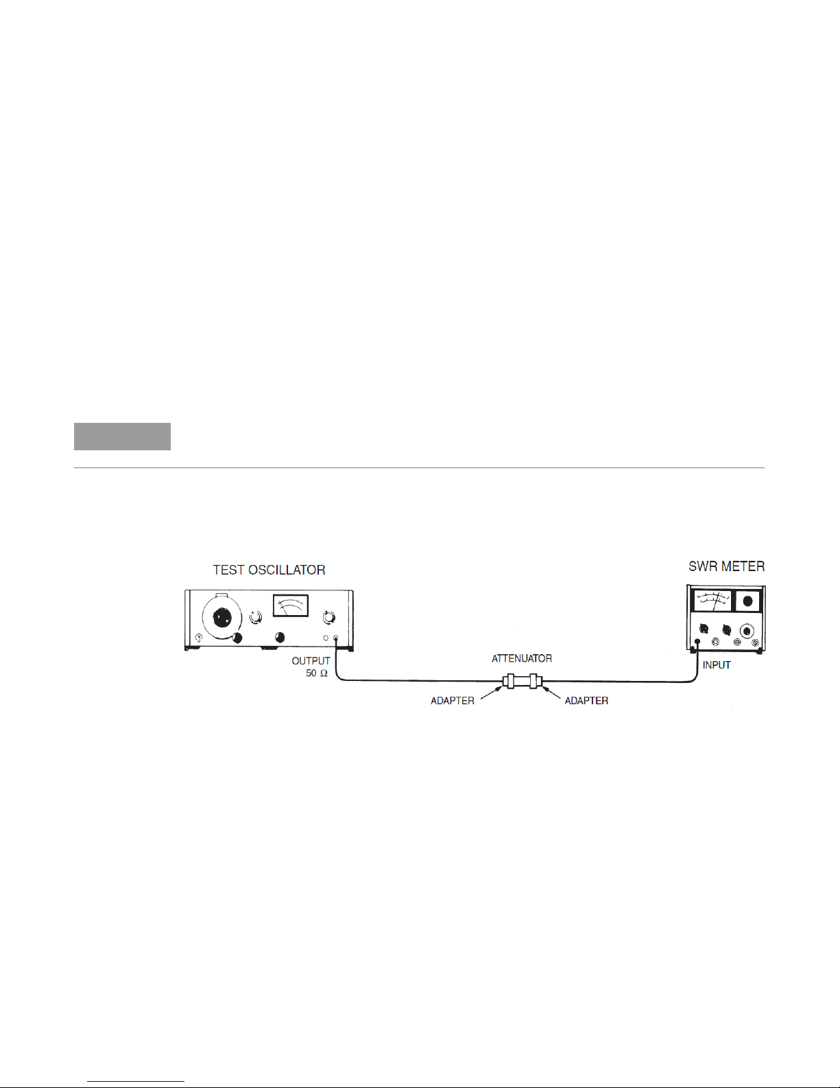
Using oscillator and SWR meter
Description
The attenuator is driven from a 50-ohm signal source at 1 kHz. The output level from the
attenuator is detected by a narrow-bandwidth voltmeter (that is, the SWR meter). A reference level
is set up on the detector using a through connection in place of the attenuator. The attenuator is
then inserted and the change in the detector level is noted. This checks the low frequency
accuracy of the attenuator.
The SWR meter used in this check is calibrated for a square-law detector and therefore the range
changes and errors (read in dB) are twice that indicated by the meter.
Quick-check procedure
1 Connect the equipment as shown in the Figure 1 except remove the attenuator and connect the
adapters directly together.
Figure 1 Equipment setup using oscillator and SWR meter
1 Set the test oscillator to 0.3 Vrms at 1 kHz.
2 Set the SWR meter range to 2 dB (expanded) or for the 3 dB, 6 dB, and 10 dB (expanded) as
appropriate and adjust its bandwidth to the center of the adjustment range. Fine tune the
oscillator frequency to obtain maximum meter indication. Adjust the oscillator output to obtain
the SWR meter reading in the table below.
3 Connect the attenuator into the system, adjust the SWR meter range switch as listed in
Table 11, and verify that the SWR meter indicates within the limits as shown Ta ble 11.
Keysight 849x and 1158x Operating and Service Manual 21
Page 22

Tab le 11 SWR verification
Attenuation (dB) SWR meter range (dB)
Meter indication (dB)
Minimum Actual Maximum
0 (system cal)
2 (or 10)
[a]
Set to 0.5 (or 0.0)
3101.35 1.65
6120.85 1.15
10 14 0.75 1.25
20 12 0.25 0.75
30 16 1.00 2.00
40 22 -0.25 1.25
50 26 0.75 2.25
60 32 -0.50 1.50
[a] Set SWR meter range to 10 dB and power level to 0.0 dB for 3 dB, 6 dB, and 10 dB attenuators only.
[a]
22 Keysight 849x and 1158x Operating and Service Manual
Page 23

Using network analyzer
Description
All four s-parameters of the attenuator are measured using a network analyzer that is already
calibrated with the necessary settings.
Quick-Check Procedure
Use correct cables and adapters on the test ports of the network analyzer. This depends on the
type of the attenuator being checked. The equipment setup is as illustrated in Figure 2.
1 Calibrate the network analyzer with appropriate settings and setup necessary.
2 Measure the S21 or/and S12 of the attenuator. Compare with the specification to verify its
electrical performance.
3 Measure the S11 and S22 of the attenuator. Compare with the specification to verify its
electrical performance.
Figure 2 Equipment setup using network analyzer
Keysight 849x and 1158x Operating and Service Manual 23
Page 24

Making Connections
The attenuators should not bear any force or weight contributed by other devices connected to
them. The attenuators are bidirectional, that is, the signal may be inserted from either end.
8490D/G
The 8490D 2.4-mm connectors mate with other 2.4-mm connectors of the opposite sex.
The 8490G 1.85-mm connectors mate with other 1.85-mm connectors of the opposite sex.
Figure 3 2.4-mm/1.85mm connector diagram
24 Keysight 849x and 1158x Operating and Service Manual
Page 25

8491A/B
NOTE
The 8491A/B type-N connectors mate with all type-N connectors whose dimensions conform to
IEE STD 287.
Do not mate with 0.071 inch diameter pin male connector. Damage will result.
Figure 4 Type-N connector diagram
Keysight 849x and 1158x Operating and Service Manual 25
Page 26

8493A/B
The 8493A/B has a male SMA jack on one end and a female SMA on the other. These connectors
mate with the opposite sex SMA connectors
Figure 5 SMA connector diagram
26 Keysight 849x and 1158x Operating and Service Manual
Page 27
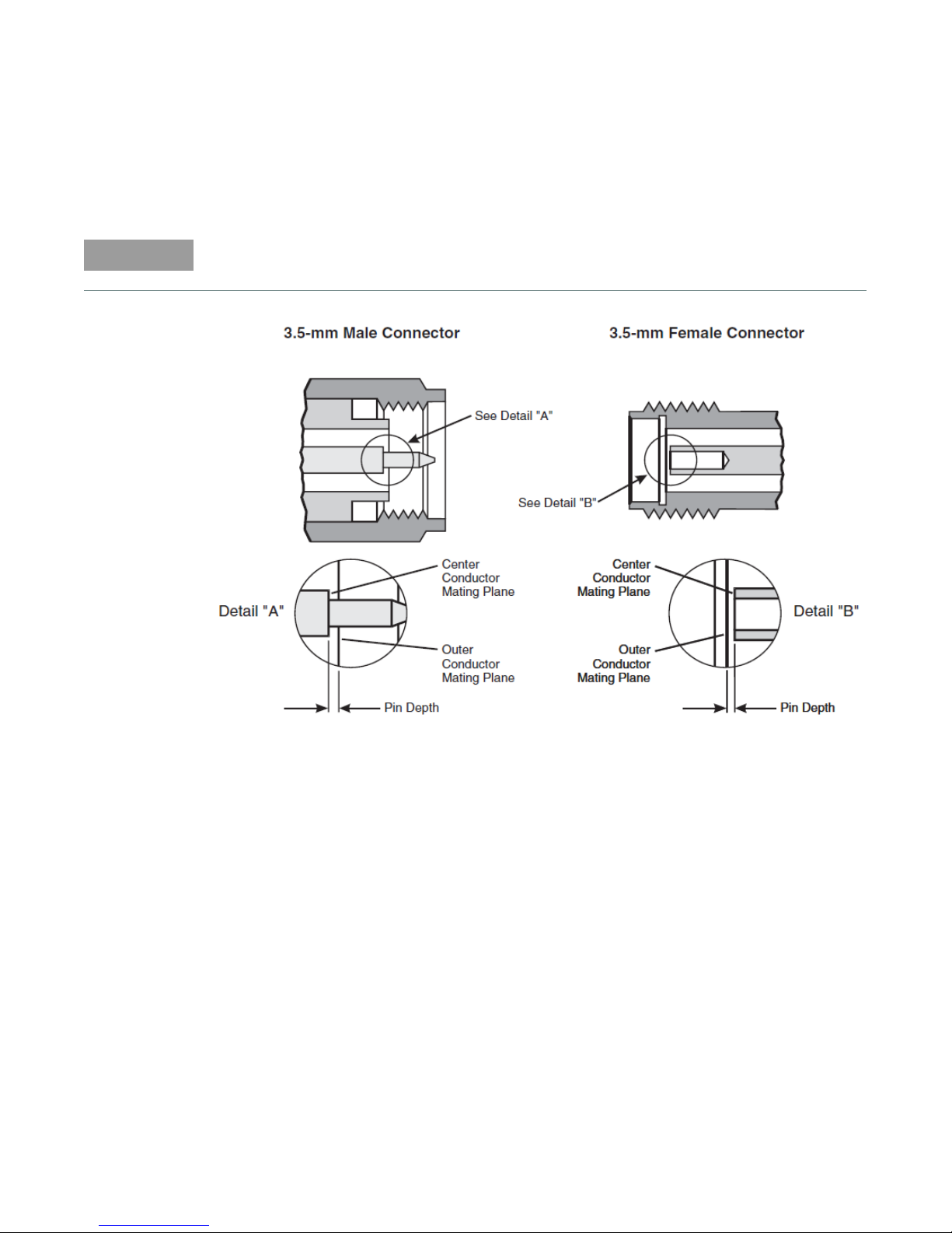
8493C
NOTE
The 8493C has a male 3.5-mm connector on one end and a female 3.5-mm connector on the other
side. These connectors mate with the opposite sex 3.5-mm or SMA connectors.
Continued mating with SMA connectors could degrade the 3.5-mm connector.
Figure 6 3.5-mm connector diagram
Keysight 849x and 1158x Operating and Service Manual 27
Page 28

Performance Test
The attenuators can be tested to the accuracy of the specifications with a network analyzer or
equivalent equipment of suitable accuracy. If a network analyzer is available, test the instrument
using the procedure in the analyzer’s operating manual.
28 Keysight 849x and 1158x Operating and Service Manual
Page 29

Service Instructions
Repair
The 8490D/G, 8491A/B the 8493A/B/C attenuators are not recommended for repair since the
cards must be mounted in cartridges to test and testing costs more than a replacement attenuator.
Maintenance
The connectors, particularly the connector faces, must be kept clean. This is especially true of the
8493A/B/C.
For instruction on connecting and care of your connectors, refer to the Microwave Connector Care
Quick Reference Card (08510-90360).
Keysight 849x and 1158x Operating and Service Manual 29
Page 30

THIS PAGE HAS BEEN INTENTIONALLY LEFT BLANK.
30 Keysight 849x and 1158x Operating and Service Manual
Page 31

This information is subject to change
without notice. Always refer to the
Keysight website for the latest
revision.
© Keysight Technologies 2014 - 2018
Edition 6, November 27, 2018
Printed in Malaysia
*08491-90077*
08491-90077
www.keysight.com
 Loading...