

Page 1

Owner’s Manual
Questions?
Call Us Toll Free
Keys Fitness Helpline
1-888-340-0482
ST-PR
215-00090
08/06 Rev B
Model Name : ST-PR
Manufactured Date :
PO # :
Model Name Decal Location
Page 2

Table of Contents
Important Safety Information 3
Assembly 4-11
Parts List 12
Exploded View 13
Warranty Information 14
2
Page 3

Important Safety Information
Please read all instructions carefully before using this product.
SAFETY TIPS
Consult with your physician before engaging in any vigorous exercise. Know your heart rate
and/or pulse as well as your physician-recommended heart rate training zone. Proper medical
clearance is recommended for anyone beginning an exercise program especially if you are 35
years of age or older or suffer from heart respiratory problems.
- Warm-up before any exercise program with 8 minutes of aerobic-like activity followed
by stretching from head to toe.
- Wear comfortable clothes that allow freedom of movement and are not tight or
restricting.
- Wear comfortable shoes made with good support and non-slip soles.
- Breath naturally, never holding your breath during an exercise.
- Perform exercises consistently with proper technique and pass through a full range of
motion.
- Increase resistance by adding heavier weights. Decrease resistance by using lighter
weights.
- Always use a spotter for safety.
- Avoid over-training. You should be able to carry on a conversation while exercising.
- After an exercise session. Cool down with slow stretching, cycling or walking.
EXERCISE DEFINITIONS:
Sets: A set is one complete routine of exercises. Complete 1-3 sets for each exercise.
Repetitions: (referred to as reps) Is the number of times you perform an exercise in a row.
We recommend beginning with 6 reps and increasing up to 12 reps as indicated below.
Novice: Start with one set of 8-12 reps. Once you can complete the entire set of 12 reps consecutively, progress to the intermediate level.
Intermediate: Complete 2 sets of 8-12 reps once you can complete two sets of 12 reps consecutively, progress to the advanced level.
Advanced: Complete 3 sets of 12 reps
DISCLAIMER:
Keys Fitness is not responsible for the misuse of any of its products or for any injury sustained
while using any Keys Fitness product. The consumer uses any or all of Keys Fitness Products at
their own risk.
BEFORE YOU BEGIN:
Before you begin assembly of your Keys Fitness product, please take a moment to review the
hardware and parts list on the following pages. Each part has been illustrated and numbered
for easy identification.
Check this list against the contents of your package to make sure you have all required parts.
If any parts are missing, please do not return this product to the store. Contact our service
department immediately at
1-888-340-0482
and we will rush you any parts you may require.
3
Page 4

Assembly
Assembly Hardware
4
Page 5

Assembly
NOTE: Hand tighten bolts and nylon nuts until machine is fully assembled.
STEP 1
Connect the Left and Right Stabilizer (#1) & (#2) by a Rear Stabilizer
(#3). Align the holes and secure themwith one 6 ¼”x 2”Bracket (#41),
two M10 x 90 Carriage Bolts (#37), Washers Dia10 (#39), and M10
Aircraft Nuts (#38) at each end of the Rear Stabilizer.
Attach one Upright Beam (#5) to the Left Stabilizer (#1). Secure it
with one 8 ½”x 2 ¾”Bracket (#12), twoM10 x 70 Carriage Bolts (#36),
Washers Dia10 (#39), and M10 Aircraft Nuts (#38). Repeat the same
procedure to install the other Upright Beam to Right Stabilizer (#2).
5
Page 6
Assembly
NOTE: Hand tighten bolts and nylon nuts until machine is fully assembled.
STEP 2
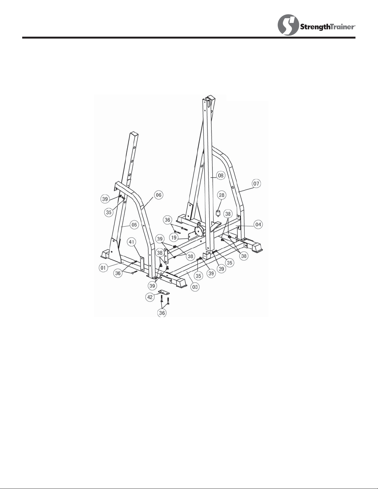
Attach the Left Support (#6) onto the Left Stabilizer (#1). Secure it with one 4 ¾”x
2” Bracket (#42), two M10 x 70 Carriage Bolts (#36), Washers Dia10 (#39), and
M10 Aircraft Nuts (#38) from the bottom up.
Attach the front of the Left Support (#6) to the Left Upright Beam(#5). Secure it
with one M10 x 20 Hex Bolt (#35) and Washer Dia10 (#39).
Repeat Step A & B above to install the Right Support (#7) on the right side.
Connect the Cross Brace (#4) in between the two Supports (#6) & (#7). Secure it
with one 6 ¼”x 2”Bracket (#41), two M10 x 70 Carriage Bolts (#36), two Washers
Dia10 (#39), and two M10 Aircraft Nuts (#38) on each end of the Cross Brace.
6
Page 7
Assembly
NOTE: Hand tighten bolts and nylon nuts until machine is fully assembled.
STEP 2 Cont.
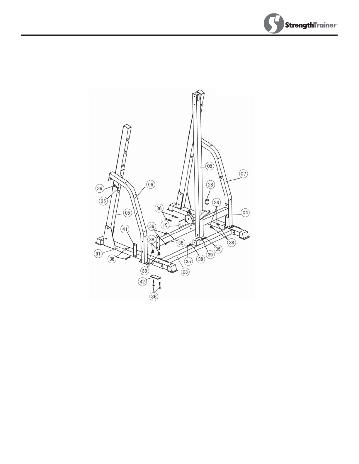
Attach the bottomof Vertical Frame (#8) to the bracket on the Rear
Stabilizer (#3). Secure the Vertical Frame to the Rear Stabilizer with two
M10 x 20 Hex Bolts (#35) and Washers Dia10 (#39). Secure the Vertical
Frame (#8) to the Cross Brace (#4) with two M10 x 70 Carriage Bolts
(#36), one 5 1/8”x 2 ¾”Bracket (#19), two Washers Dia10 (#39), and
M10 Aircraft Nuts (#38).
Attach a Bumper (#28) onto the lower Vertical Frame (#8).
7
Page 8
Assembly
NOTE: Hand tighten bolts and nylon nuts until machine is fully assembled.
STEP 3
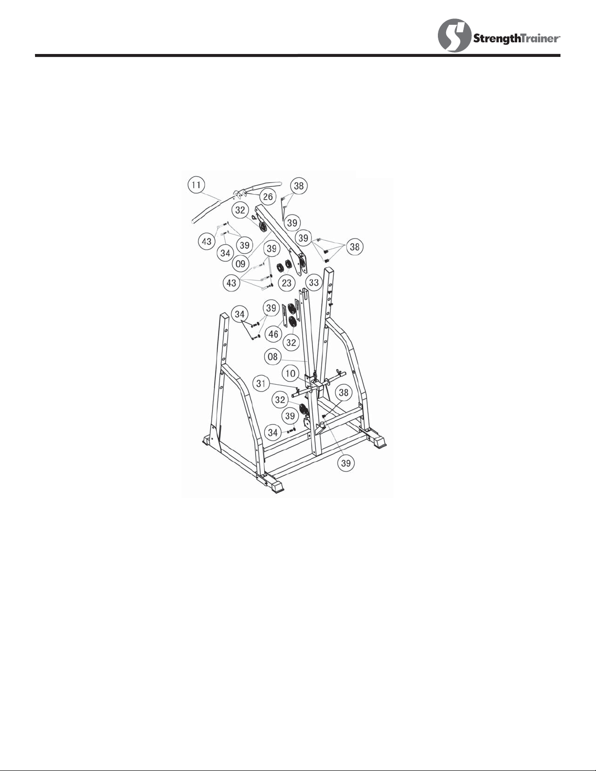
Slide the Sliding Weight Holder (#10) onto the Vertical Frame (#8). Attach two
Spring Clips 1”(#31) to the posts on the Sliding Weight Holder.
Insert the Upper Frame (#9) onto the top opening on the Vertical Frame (#8). Align
the bottomhole on the top of the Vertical Frame. Secure it with one M10 x 80 Hex
Bolts (#43) and two Washers Dia10 (#39).
Attach the Lat Bar Holder (#26) to the front of Upper Frame (#9). Secure it with
one M10 x 80 Hex Bolts (#43), two Washers Dia10 (#39), and one M10 Aircraft Nut
(#38).
Attach the Lat Bar (#11) to the Cable End with a Clip (#30).
8
Page 9

Assembly
NOTE: Hand tighten bolts and nylon nuts until machine is fully assembled.
STEP 4
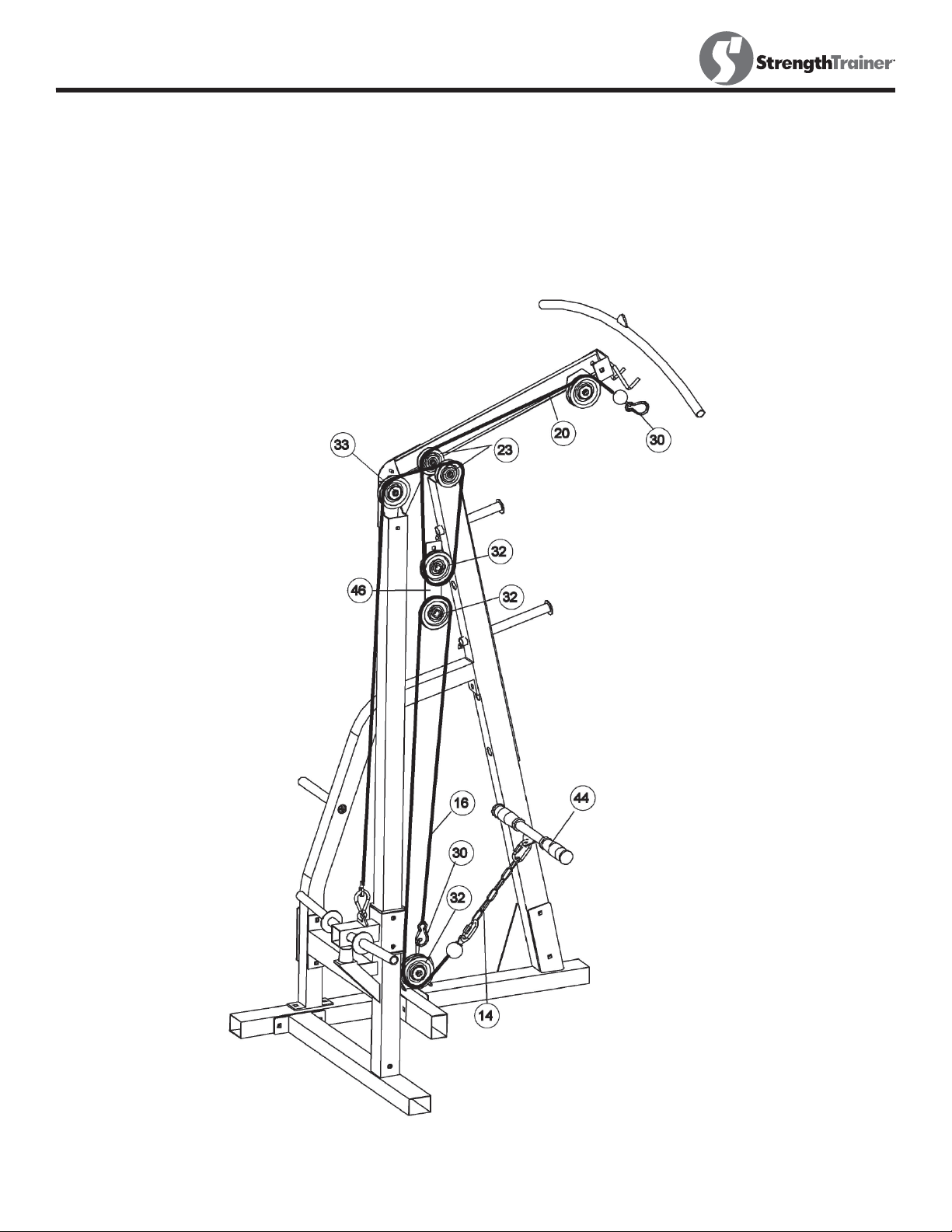
Notice:
The cable diagram below shows the proper routings of the 110”Lat Cable (#20), the 92”
Low Row Cable (#16) for the cable assembly in Steps 4 Use the diagram to be sure that
the two cables have been assembled correctly. If the cables have not been correctly routed, the Machine will not function properly and damage may occur.
Draw the end, without the rubber ball, of the 110”Lat Cable (#20) to the open bracket at
the front of the Upper Frame (#19). Install a Pulley (#32). Secure it with one M10 ×45
Hex Bolt (#34), two Washers Dia10 (#39) and one M10 Nylon Nut (#38).
Draw the Cable along the Upper Frame towards the back of the machine to the first open
bracket. Install two Pulleys (#23). Secure it with one M10 ×80 Hex Bolt (#43), twoWashers Dia10 (#39) and one M10 Nylon Nut (#38).
Pull the Cable over the top of the first Pulley (#23), Pull the Cable downward and attach
a Pulley (#32) to it. Install the two Double Floating Pulley Brackets (#46) to the Pulley.
Select any hole on the two Brackets for now. Secure them with one M10×45 Hex Bolt
(#34), two Washers Dia10 (#39) and one M10 Nylon Nut (#38). After completing the
installation, come back and adjust the tightness of the cable loop by selecting a different
hole. Let the brackets hanging for now.
Draw the Cable upward to the second Pulley (#23). Thrill through above the Pulley
(#32). Draw the Cable towards to the last bracket on the Upper Frame. Install a Pulley
(#33). Secure it with one M10 ×80 Hex Bolt (#43), two Washers Dia10 (#39) and one
M10 Nylon Nut (#38). Draw the Cable around the Pulley then pull it down to the Slide
Weight Holder (#10). Connect the Cable to the Holder and secure it with one Clip (#30).
Draw the end, without the rubber ball, of the 92”Low Row Cable (#16) to the opening at
the upper of the Cross Brace (#04). Install a Pulley (#32) to the opening. Secure it with
one M10 x 45 Allen Bolt (#34), two Washers Dia10 (#39) and one M10 Nylon Nut (#38).
Draw the Cable underneath around the Pulley then pull upward to the Double Floating
Pulley Brackets (#46). Install a Pulley (#32). Secure it with one M10 ×45 Allen Bolt
(#34), twoWashers Dia10 (#39) and one M10 Nylon Nut (#38). Pull the Cable around
the Pulley then downward to the bracket on the the Cross Brace (#04). Secure it with
one Clip (#30).
9
Page 10
Assembly
NOTE: Hand tighten bolts and nylon nuts until machine is fully assembled.
STEP 4 Cont.
10
Page 11
Assembly
NOTE: Hand tighten bolts and nylon nuts until machine is fully assembled.
STEP 5
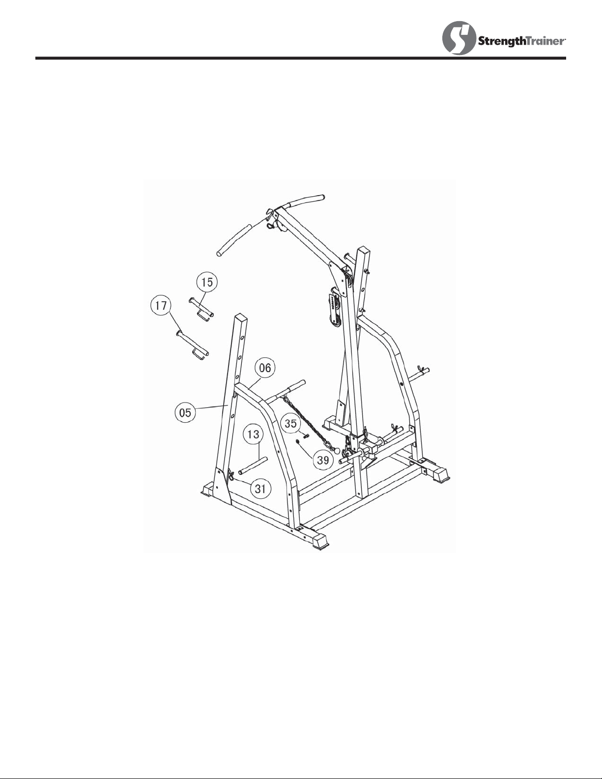
Attach two Weight Plate Holders (#13) to the holes on the side of
each Left and Right Supports (#6) &(#7). Secure each with a M10
x 20 Hex Bolt (#35) and Washer Dia10 (#39). Attach a Spring Clip
1”(#31) to each weight plate holder.
Insert the two Bar Catches (#15) into upper selected hole on the left
and right Upright Beam. Insert the two Long Bar Catches (#17) into
the bottomhole on the Left and Upright Beam.
11
Page 12

Parts List
ST-PR Parts List Rev A
Ref # Part # Description Qty
1 223-00861 LEFT STABALIZER, ST-PR 1
2 223-00862 RIGHT STABALIZER, ST-PR 1
3 223-00863 REAR STABALIZER, ST-PR 1
4 223-00864 CROSS BRACE, ST-PR 1
5 223-00865 UPRIGHT BEAMS, ST-PR 2
6 223-00866 LEFT SUPPORT, ST-PR 1
7 223-00867 RIGHT SUPPORT, ST-PR 1
8 223-00868 VERTICAL FRAME, ST-PR 1
9 223-00869 UPPER FRAME, ST-PR 1
10 219-00340 SLIDING WEIGHT HOLDER, M-PR 1
11 223-00400 LAT BAR#11 M-PR/ST-PR 1
12 210-00168 BRACKET, 8 ½ X 2 ¾ M-PR/ST-PR 2
13 219-00291 Weight Plate Holder M-PR/ST-PR 2
14 210-00101 CHAIN M-PR/ST-PR 1
15 223-00401 BAR CATCH#15 M-PR/ST-PR 2
16 229-00058 LOW ROW CABLE, M-PR/ST-PR 1
17 223-00402 LONG BAR CATCH#17 M-PR/ST-PR 2
18 206-00220 ROUND INNER PLUG, 25X2.5 2
19 210-00169 BRACKET, 5 1/8X2 ¾ M-PR/ST-PR 1
20 229-00059 LAT CABLE#20 M-PR/ST-PR 1
21 206-00154 Lat Bar Grip M-PR/ST-PR 2
22 206-00155 Stabilizer End Cap M-PR/ST-PR 4
23 206-00156 Pulley D78X20 M-PR/ST-PR 2
24 206-00157 Square Inner Plug 2 x 2 ¾ M-PR 2
25 206-00158 Sliding Block sleeve M-PR/ST-PR 2
26 219-00292 LAT BAR HOLDER M-PR/ST-PR 1
27 206-00065 2" SQUARE PLUG 1
28 206-00160 BUMPER 1
29 206-00161 ROUND INNER PLUG, 25x2 1
30 210-00102 CLIP M-PR 4
31 210-00103 SPRING CLIP 1" 4
32 206-00162 PULLEY D100*24 M-PR/ST-PR 4
33 206-00163 Pulley D100X55 M-PR/ST-PR 1
34 202-00164 HEX BOLT, M10*45, M-PR/ST-PR 4
35 202-00296 HEX BOLT, M10X20 6
36 202-00166 CARRIAGE BOLT, M10*70, M-PR/ST-PR 14
37 202-00418 BOLT, M10X90 4
38 202-00168 AIRCRAFT NUT, M10 M-PR/ST-PR 26
39 202-00169 WASHER, DIA10 M-PR/ST-PR 40
40 210-00104 LONG BUMPER BRACKET M-PR/ST-PR 2
41 210-00105 BRACKET 6 1/4 * 2" M-PR/ST-PR 4
42 210-00106 BRACKET 4 3/4 * 2" M-PR/ST-PR 2
43 202-00163 HEX BOLT M10*80, M-PR/ST-PR 4
44 219-00293 LOW ROW BAR M-PR/ST-PR 1
45 206-00164 LOW ROW BAR GRIP M-PR/ST-PR 2
46 210-00107 DOUBLE PULLEY BRACKET M-PR/ST-PR 2
# 202-00376 BOLT PACK, M-PR/ST-PR 1
# 215-00090 MANUAL ST-PR 1
12
Page 13
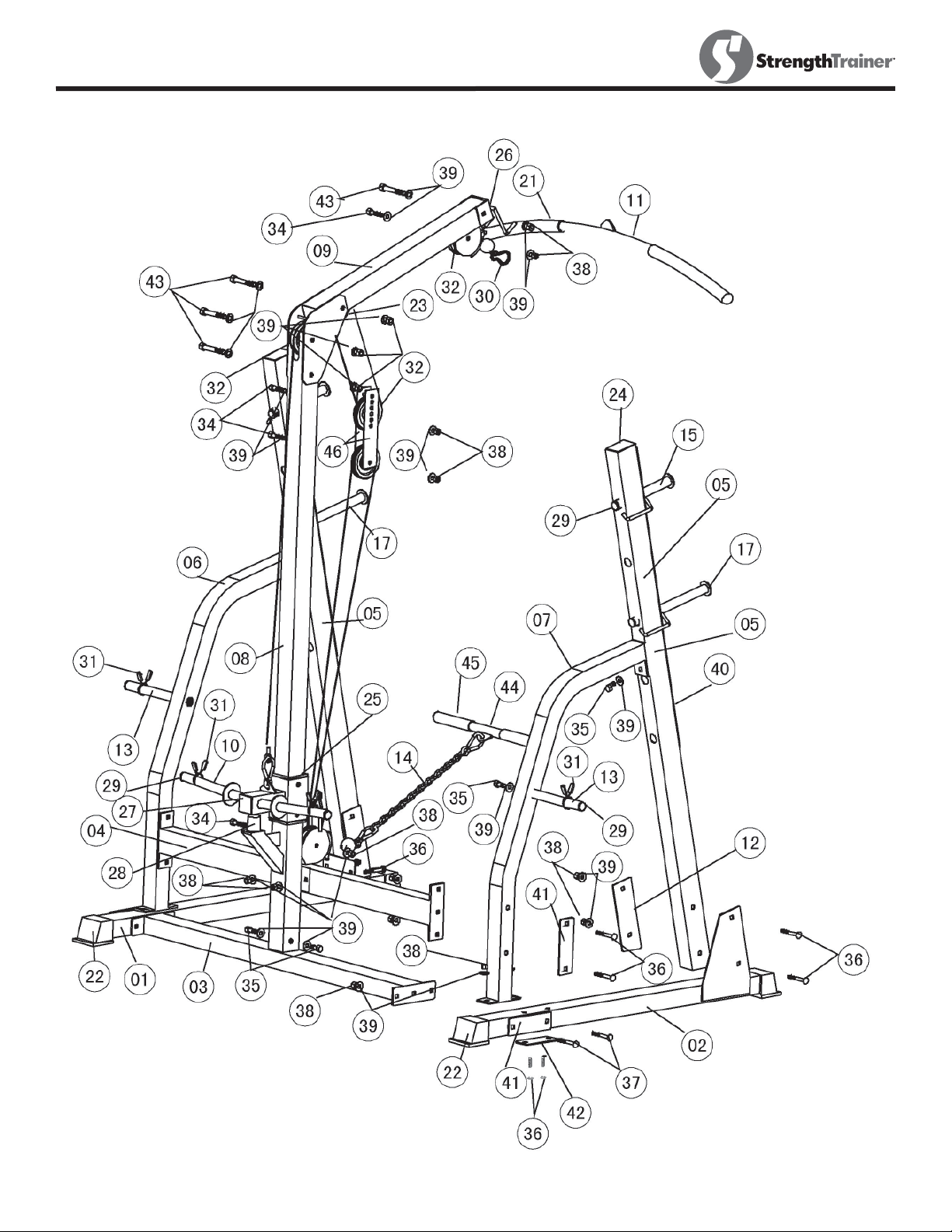
Exploded View
13
Page 14

Warranty
KEYS FITNESS PRODUCTS, L.P.
STRENGTH TRAINER
WARRANTY
Keys Fitness Products L.P. warrants this product for a period of 90 days on parts and lifetime
on the frame from the original date of purchase. This warranty covers the product from defects
in materials and workmanship for the original purchaser. Using this product for commercial
purposes, products damaged by misuse, abuse, or from shipping, moving and storage will void
this warranty.
Replacement parts are available from Keys Fitness Products L.P.
To contact us for customer service or replacement parts, call
CUSTOMER SERVICE
If you have any questions regarding this or any Keys Fitness product, or if we may be of
assistance in any way, please do not hesitate to call our toll free number
1-888-340-0482.
1-888-340-0482.
14
Page 15

Keys Fitness Products, L.P.
4009 Distribution Drive, Suite 250
Garland, Texas 75041
Customer Service: 1-888-340-0482
 Loading...