

Page 1
Owner’s Manual
Keys Fitness KF-3.0T
Treadmill
Customer Service
(888) 340-0482
Keys Fitness Products
4009 Distribution Drive
Suite 250
Garland, TX 75041
www.keysfitness.com
CAUTION! Read all precautions
and instructions in this manual
before using this equipment.
Model Name : KF-3.0T
Serial Number :
415-00179
10/07 Rev B
Write down for future reference
Serial Number Decal Location
Page 2

Table of Contents
Important Safety Information 3
Before You Start 4
Assembly 5
Parts Identifier 5
Assembly Steps 6
Moving Instructions 10
Power Requirements 11
Console Instructions 12
Overview 12
MP3 Input 12
Program Operation 14
Program Profiles 17
Monitoring Your Heart Rate 19
Workout Information 21
Frequency: How Often Should You Exercise 21
Intensity: How Hard Should You Exercise 21
Weight Management 21
Exercise Practice Procedures 22
Workout: Brisk and Rhythmic Exercise 22
Cool Down: Slow and Relaxed Exercise 22
Exercise Guidelines 23
Calibration Sequence 26
Change to MPH or KPH 26
Belt Adjustment 27
Maintenance Instructions 28
Error Messages 29
Troubleshooting Guide 30
Parts List 31
Exploded View 32
Warranty 33
2
Page 3

Important Safety Information
WARNING! Before using this treadmill or starting any exercise program, consult your
physician. This is especially important for persons over the age of 35 and/or persons with
pre-existing health problems. The manufacturer or distributor assumes no responsibility for
personal injury or property damage sustained by or through the use of this product.
WARNING! To reduce the risk of electrical shock, burns, fire, or other possible injuries to the
user, it is important to review this manual and the following precautions before operation.
SAVE THESE INSTRUCTIONS
SAFETY PRECAUTIONS AND TIPS
1. Always secure Safety Key firmly to waistband.
2. It is the owner’s responsibility to ensure that all users of this treadmill have read the
Owner’s Manual and are familiar with warnings and safety precautions.
3. This treadmill has a user maximum capacity of 325 pounds.
4. The treadmill should only be used on a level surface and is intended for indoor use only.
The treadmill should not be placed in a garage, patio, or near water and should never be
used while you are wet. Keys Fitness recommends a treadmill mat be placed under the
treadmill to protect floor or carpet and for easier cleaning.
5. Follow safety information in regard to plugging in your treadmill. Keep the power cord away
from the incline wheels and do not run the power cord underneath your treadmill. Do not
operate the treadmill with a damaged or frayed power cord.
6. Wear comfortable, good-quality walking or running shoes and appropriate clothing. Do not
use the treadmill with bare feet, sandals, socks or stockings.
7. Always straddle the belt and allow it to start moving before stepping onto the belt.
8. Hold on to handlebar when adjusting speed or other controls.
9. Always examine your treadmill before using to ensure all parts are in working order.
10. Allow the belt to fully stop before dismounting.
11. Pets should never be allowed near or on the treadmill.
12. Close supervision is necessary when this appliance is used by or near children, invalids or
disabled persons.
13. Never operate the treadmill where oxygen is being administered, or where aerosol products
are being used.
14. Never insert any object or body parts into any opening.
15. For safety and to prevent damage to your treadmill, no more than one person should use
the treadmill at a time.
16. Always unplug the treadmill before cleaning and/or servicing. Service to your treadmill
should only be performed by an authorized service representative, unless authorized and/or
instructed by the manufacturer
17. Failure to follow these instructions will void the treadmill warranty.
18. Never leave the treadmill unattended when plugged in. Unplug from outlet when not in use
and before service or maintenance.
19. Always unplug this appliance immediately after using and before cleaning. To disconnect,
turn all controls to the off position, then remove plug from outlet.
3
Page 4
Before You Start
Thank you for purchasing the Keys Fitness KF-3.0T Treadmill! This quality product you
have chosen was designed to meet your needs for cardiovascular exercise. Before you start,
please read the Owner's Manual and become familiar with the operation of your new treadmill.
Remember to take the time to perform the stretching exercises provided to avoid
injury.
Do not stand on the walking belt while pressing the Power button or Start/Stop button.
Always adjust the speed of the treadmill in small increments as this treadmill is capable of
high speeds.
If you are taking medication, consult your physician to see if the medication will affect your
exercise heart rate.
If you have heart problems, you are not active, and/or are over the age of 35 years, do not
use the pre-set treadmill programs or start an exercise program without first contacting and
receiving approval from your physician.
To avoid the risk of electrical shock, always keep the console dry. Do not spill liquids on the
console. Keys Fitness recommends a sealed water bottle for beverages consumed while using
the treadmill.
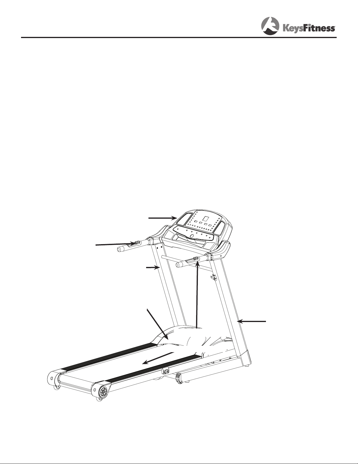
Please review the following drawing below to familiarize yourself with the listed
parts. This manual covers several treadmills, so the one pictured below may not be
identical to your particular model.
INCLINE SWITCH
CONSOLE
LEFT UPRIGHT
MOTOR COVER
RIGHT UPRIGHT
SPEED SWITCH
RUNNING BELT
4
Page 5
Assembly: Parts Identifier
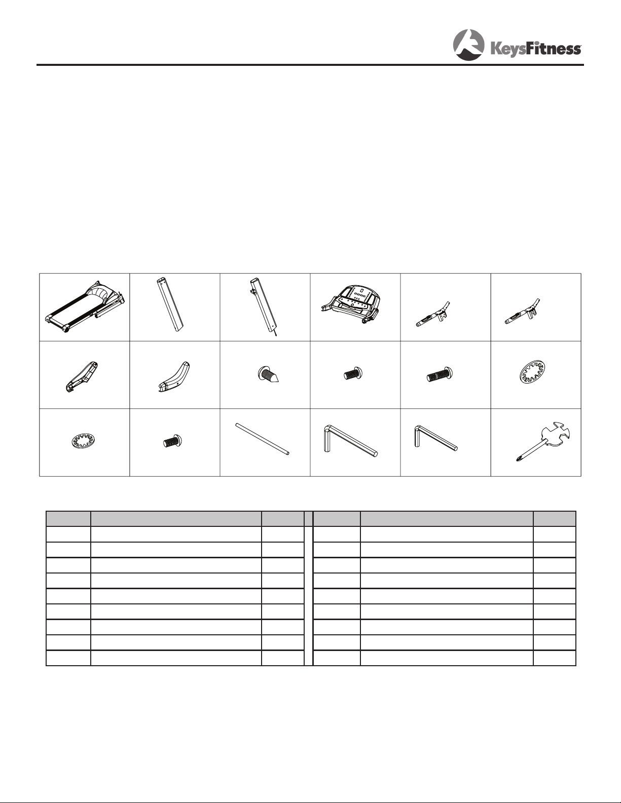
Ref # Description Qty Ref # Description Qty
U2T1 MAIN FRAME 1 U4J24 SCREW ST4.2*12 6
U4T4 LEFT UPRIGHT 1 U4J5 BOLT M10*25 12
U4T5 RIGHT UPRIGHT 1 U4J7 BOLT M8X52 5
U2D1 CONSOLE 1 U4J28 SAWTOOTH WASHER #8 6
UAS29 LEFT PROTECTION COVER 1 U4J27 SAWTOOTH WASHER #10 12
UAS30 RIGHT PROTECTION COVER 1 UAW8 #6 ALLEN WRENCH 1
UAT6 LEFT HANDLEBAR 1 UAW9 #5 ALLEN WRENCH 1
UAT7 RIGHT HANDLEBAR 1 UAW10 WRENCH W/SCREW DRIVER 1
U4T11 CROSS BAR 1
U4J4 BOLT M8X26 1
U2T1
U4T4
U4T5
U2D1
UAS29
UAS30
U4J24
U4J5
U4J27
UAW8 UAW9 UAW10
U4J28
U4J7
UAT6
UAT7
U4T11
U4J4
The Keys Fitness KF-3.0T Treadmill will require assembly before operating. Place unopened
box on a clean, level surface. After opening the box, remove any packing material from the
treadmill.
Do not throw away any packing materials until the unit is working properly.
Do not remove unit from box until it has been fully assembled.
Make sure the electrical cord will easily reach an electrical outlet.
If at anytime you need assistance with assembly, call 888-340-0482.
Locate the hardware pack and identify the following parts required for assembly.
Tools:
1. Allen Wrench- 3/16”
2. Allen Wrench- 7/32”
3. Phillips Screwdriver
5
Page 6
Assembly
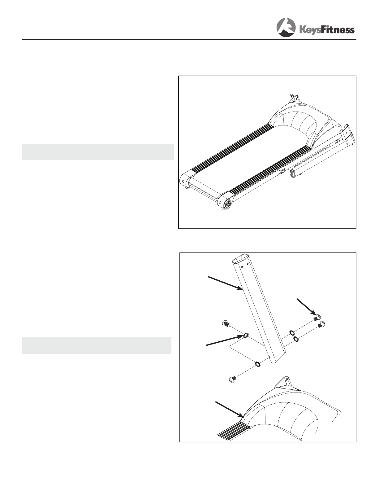
Assembly requires the included Allen wrench and Phillips screwdriver. Leave the unit on the
original packing material to assemble all parts.
Do not plug in the power cord until all assembly steps are completed.
1. Remove top cover of box, and break
the sides of the box to create a level
assembly surface. After opening the box,
remove any packing material from the
treadmill. Carefully cut the strap surrounding the treadmill, only while the
treadmill is laying flat.
Do not remove unit from box until it
has been fully assembled.
2. Locate the left upright. Slide the left
upright onto the base frame.
Secure the left upright to the base frame
by using four bolts M10x25 and four wash-
ers #10.
Note: Do not tighten hardware until step
6 has been completed.
Figure 1: Unpacking Treadmill
Left Upright
Bolt M10x25
Washer
#10
Base Frame
Figure 2: Left Upright Installation
6
Page 7
Assembly
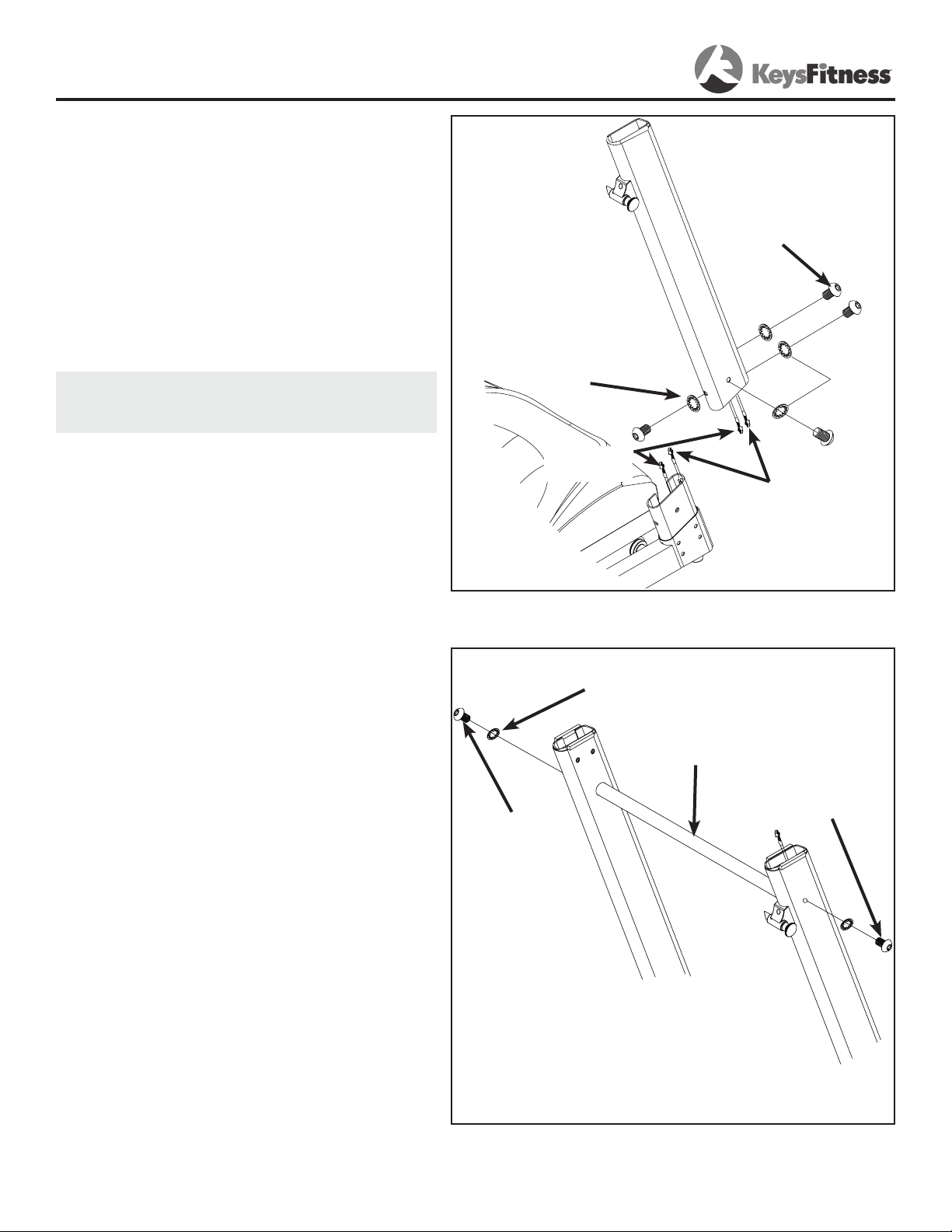
2. Locate the tight upright. Connect the
console harness together. One side of harness is located near the motor cover on
the bottom right side. The other end is
located inside the right upright.
Connect the amplifier harness together.
One side of harness is located near the
motor cover on the bottom right side.
The other end is located inside the right
upright.
Note: Make sure that the console harness
and the amplier harness are inside of the
upright and not being pinched.
Bolt M10x25
Washer #10
Slide the left upright onto the base frame.
Secure the left upright to the base frame
by using four bolts M10x25 and four wash-
ers #10.
4. Locate the cross bar. Slide the cross
bar in between the left and right uprights.
Secure the cross bar using one washer #8
and one bolt M8x52 on the right side and
one washer #8 and one bolt M8x26 on the
left side.
Console
Harness
Amplier
Harness
Figure 3: Right Upright Installation
Washer #8
Crossbar
Bolt M8x26
Bolt M8x52
Figure 4: Crossbar Installation
7
Page 8
Assembly
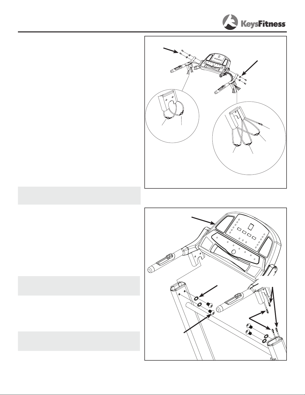
EKG
Harness
Toggle
Harness
EKG
Harness
Toggle
Harness
Amplifying
Wire
Console
Harness
4. Feed the wires coming out of right side
of the console through the hole located on
the tube of the right handlebar. Connect
the amplifier wire coming from the handlebar to the amplifier wire coming from the
console. Connect the EKG harness and the
toggle harness coming from the handlebar
to the EKG harness and the toggle harness
coming from the console. Secure the right
handlebar to console using two bolts M8x52
and two washers #8.
Feed the wires coming out of the left side
of the console through the hole located on
the tube of the left handlebar. Connect the
EKG harness and the toggle harness coming from the handlebar to the EKG harness
and the toggle harness coming from the
console. Secure the left handlebar to console using two bolts M8x52 and two washers #8.
NOTE: Make sure not to pinch or screw
through any wires when securing the left
handlebar.
Bolt M8x52
Washer #8
Figure 5: Console Assembly
6. Connect the console harness together.
One side of harness is coming from the
right upright. The other end is coming
from the console.
Attach the console onto the uprights by
sliding into the uprights.
NOTE: Make sure that the console har-
ness and amplifier harness are inside of
the upright and not being pinched.
Secure the console to the uprights using
two bolts M10x25 and two washers #10
per side.
IMPORTANT PLEASE NOTE:
Tighten all hardware installed in Step 2
through Step 6.
Console
Console
Washer #10
Harness
Amplifier
Harness
Bolt M10x25
Figure 6: Securing Console Assembly to Uprights
8
Page 9
Assembly
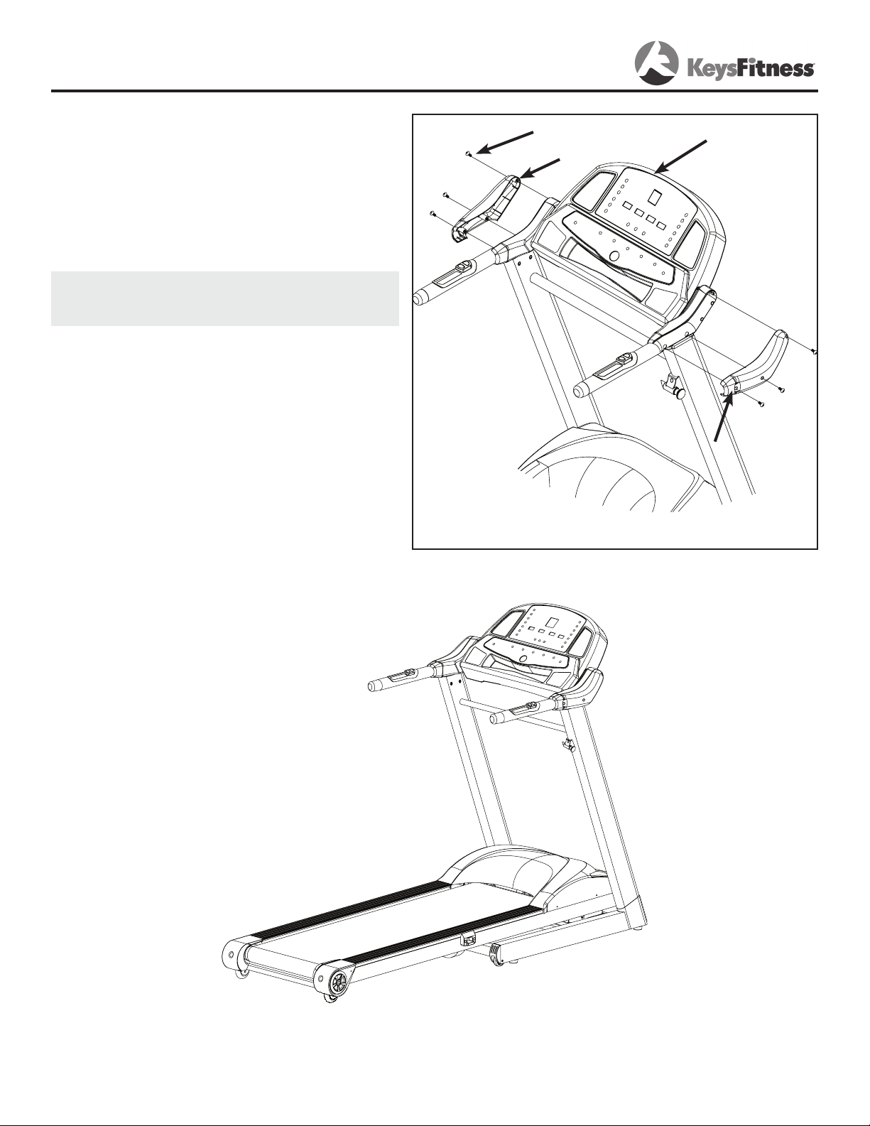
7. Locate the left and right covers.
Secure the covers to the console using
three screws on each side.
NOTE: Make sure not to pinch or screw
through any wires when securing the left
handlebar.
Screw ST4.2x12
Left Cover
Console
Right Cover
Figure 7: Cover Installation
Congratulations!
You have completed the assembly of your new KF-3.0T Treadmill!
Please remove the treadmill out of the box.
9
Page 10

Moving Instructions
Caution! To Avoid The Risk Of Injury, Never Attempt To Move The Treadmill While It
Is In The Unfolded Operating Position.
With the treadmill in the folded locked position (safety latch is engaged) grasp the handlebars
and simply start rolling to desired location. Do not attempt to move the treadmill over an
uneven or rough surface.
10
Page 11
Power Requirements
Improper connection of the equipment grounding connector can result in a risk of an
electric shock. Check with a qualified electrician or service man if you are in doubt as
to whether the product is properly grounded. Do not modify the plug provided with
the product. If plug will does not fit into the outlet, have a proper outlet installed by
a qualified electrician.
This treadmill can be seriously damaged by sudden voltage changes in your home’s electrical
power. Voltage spikes, surges, and noise interference can result from weather conditions or
from other appliances being turned on or off. To reduce the possibility of treadmill damage,
always use a dedicated surge protector (not included) with your treadmill.
Surge protectors can be purchased at most hardware stores. The manufacturer recommends
a single outlet surge protector with UL 1449 rating as a Transient Voltage Surge Suppressor
(TVSS) with UL suppressed voltage rating of 400V or less and an electrical rating of 120VAC,
15 amps.
This treadmill must be grounded to reduce the risk of electrical shock. Grounding provides
a path of least resistance for electric current should the treadmill malfunction. This treadmill
comes with an electrical cord with an equipment-grounding conductor and a grounding plug.
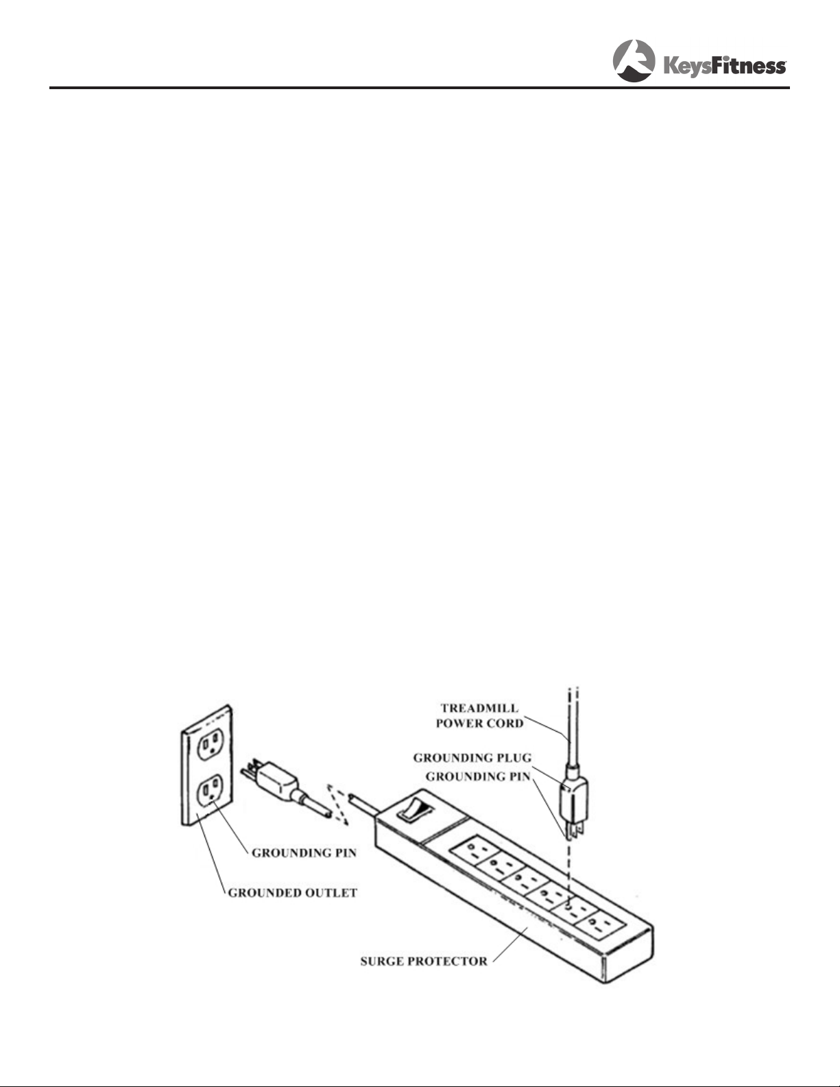
Always plug the power cord into a surge protector, and plug the surge protector into an appropriate outlet that is properly installed and grounded in accordance with all local codes and ordinances. Do not connect other equipment to the surge protector or this could cause permanent
damage to your treadmill.
This product is for use on a nominal 120-volt circuit and has a grounding plug that looks like
the plug illustrated in the drawing below.
11
Page 12
Console Instructions
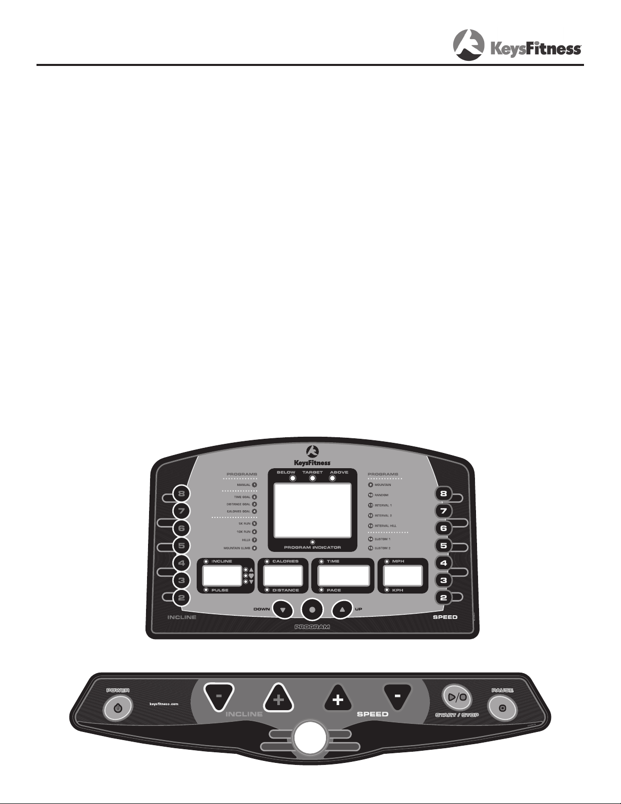
There are five display windows on the control panel to provide feedback information.
TIME/PACE
TIME: Indicates elapsed time after pressing start in minutes and seconds (0-99 minutes, 0-59
seconds)
PACE: Indicates estimated amount of time needed to complete 1 mile based on current speed.
CALORIES / DISTANCE WINDOW
CALORIES: Indicates estimated calories used based on 150 lb. person at the indicated speed,
incline, and time.
DISTANCE: Indicates Miles or Kilometers traveled in .01 increments up to 9.99 and .1 increments starting at 10.0
INCLINE / PULSE WINDOW
INCLINE: Indicates incline in percent of grade 0-12% in 0.5 increments.
PULSE: Indicates the estimated heart rate of the user when pulse grips are held. Note: It may
take several seconds for the electronics to detect and display an accurate heart rate reading.
SPEED
SPEED: Indicates MPH or KPH in .1 increments 0.6-12MPH.
CENTER BRICKYARD WINDOW
Displays an eighth of a mile track in Manual mode. Indicates position on track by a blink. In
program mode, shows the change in speed profile across the interval range (1-10) and shows
position with a blinking action. In Manual mode, the LAP counter will appear in the top center
of the window, counting each 1/8 mile lap in sequence of completion (1, 2, 3, etc.).
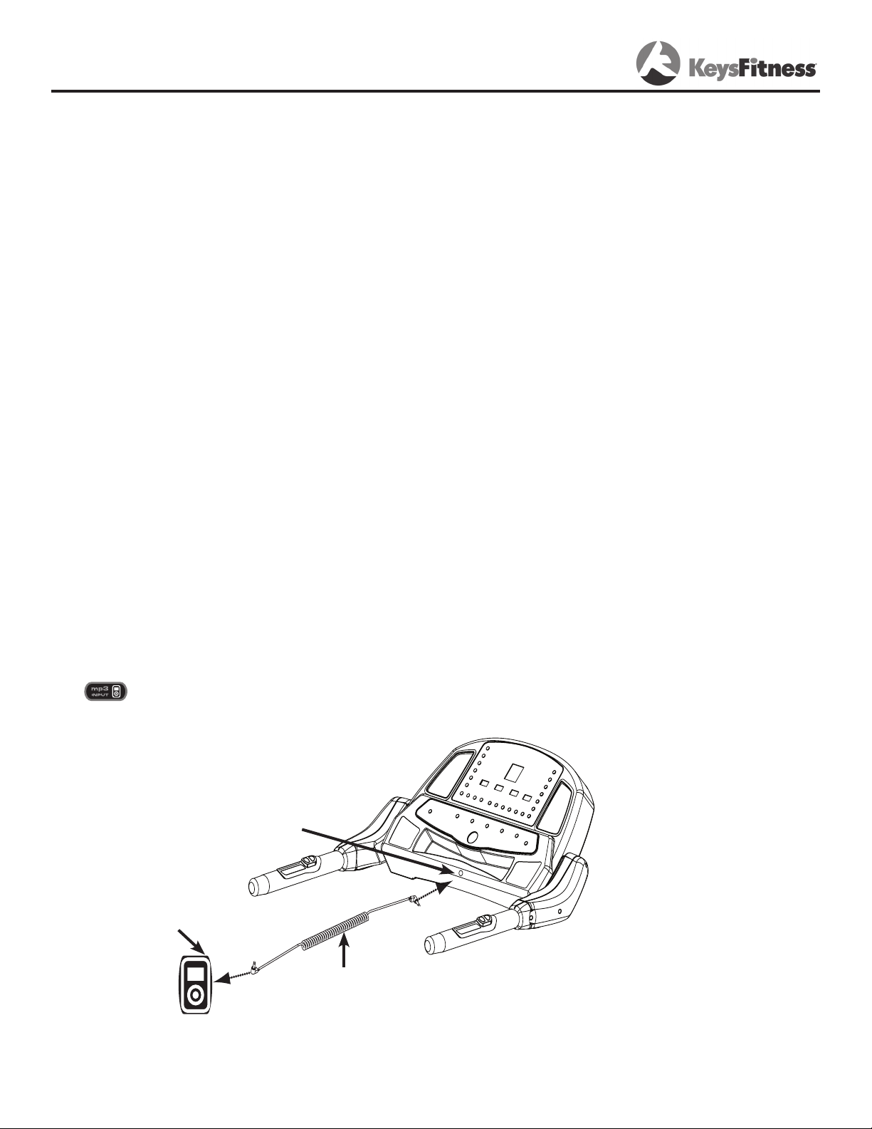
MP3 Input
The KF-3.0T is equipped with an mp3 input which allows you to listen to the music stored in
your mp3 player through the integrated speakers on the console.
To use, simply take one end of the mp3 cable provided and plug it into the output of the mp3
player. Plug the other end of the mp3 cable into the mp3 input of the treadmill. You will
see next to the input. You will need to use the controls on the mp3 player to change
songs and control the volume.
MP3 Input
MP3 Player
MP3 Cable
12
Page 13
Console Instructions
CONSOLE BUTTONS
POWER
This button is used to turn the treadmill on and off.
START/STOP
This button is used to start or stop the current program.
PAUSE
This button is used to stop your workout temporarily, and to continue from where you left off
when you are ready.
PROGRAM
This button is used to edit the settings of the desired program before it is started.
PROGRAM UP AND DOWN
These buttons are used to cycle through to the desired program.
INCLINE + and -
These buttons are used to adjust the incline value during the workout. These buttons are also
used to adjust the values when setting up your workout.
SPEED + and -
These buttons are used to adjust the speed of the treadmill during workout. These buttons are
also used to adjust the values when setting up your workout.
ONE TOUCH BUTTONS
The one touch buttons allow you to choose a preset speed and incline easily.
To use the one touch feature: Press one of the one touch numbers (2-8). You can select
from the incline set of buttons or the speed set of buttons if you would like to change the
speed or incline of your workout.
13
Page 14

Console Instructions
PROGRAM OPERATION
QUICK START / MANUAL MODE (P1)
1. Plug into a surge protector outlet. Attach the Safety Key to the treadmill console.
2. Stand on the treadmill and straddle belt. Attach safety key clip to your clothes.
3. Press POWER button. There will be an eight (8) second delay after pressing the POWER button before data can be entered.
4. Press START/STOP button. Belt will begin to move after 4 seconds. Step on belt slowly
after the belt starts moving. Speed or incline may be adjusted by using the appropriate +
(increase) or – (decrease) button.
5. To end your workout, press START/STOP button. Belt will gradually slow to zero.
6. To pause your workout, press PAUSE.
7. To re-start after pausing: Press the PAUSE button. WARNING: THE TREADMILL BELT
WILL RESUME AT THE SPEED THE TREADMILL WAS MOVING BEFORE PAUSING.
PROGRAM MODE
Plug treadmill into a surge protector outlet. Attach the Safety Key on to the treadmill console.
1. Stand on the treadmill and straddle belt. Attach safety key clip to your clothes.
2. Press POWER button. There will be an eight (8) second delay before data can be entered.
3. There are thirteen (13) pre-set and two (2) user profile programs. Refer to the following
pages for program overview that includes Speed and Incline setting for each program. Press
the PROGRAM UP or DOWN button to select which program you wish to use. Press PROGRAM
to confirm selection.
4. Press START/STOP button. Belt will begin to move after 4 seconds. Step on belt slowly after
the belt starts moving.
COOL DOWN
At the end of the program, the unit will enter a Cool Down program with a fixed time of 2 minutes. At this time, the TIME window will continue to show the entered Time. The Speed and
Incline will go to 1/2 of their current settings. For example, If you are running at 5 MPH with
an Incline of 4%, when the unit goes into Cool Down, Speed will decrease to 2.5MPH and the
Incline will decrease to 2%. After the 2 minute Cool Down, the unit will self power down.
NOTE: If any button is pressed during the 2 minute Cool Down period, the unit will change to
Manual Mode (see P1). At this time, full manual control of treadmill settings such as Speed and
Incline are available to the User.
TIME GOAL (P2):
Program allows user to set desired TIME of workout. Once the desired TIME is accomplished,
the treadmill will enter Cool Down.
1. Press PROGRAM UP button or PROGRAM DOWN button until P2 is selected. Press PROGRAM.
The TIME window will blink. Use the SPEED + or – arrows or toggles to select your workout
time. Press PROGRAM.
2. The SPEED window will then blink. Use the SPEED + or – arrows or toggle to select the
speed for your workout. Press PROGRAM.
3. The INCLINE window will then blink. Use the INCLINE + or – arrows or incline toggles to set
your workout incline. Press PROGRAM.
4. To start, press the START/STOP button.
14
Page 15

Console Instructions
DISTANCE GOAL (P3):
Program will allow user to set desired DISTANCE for workout. Distance will count up to desired
Distance. Once the desired DISTANCE is accomplished, the treadmill will enter Cool Down.
1. Press PROGRAM UP button or PROGRAM DOWN button until P3 is selected. Press ENTER.
The DISTANCE/CALORIE window will blink. Use the SPEED + or – arrows or toggles to select
your workout distance. Press PROGRAM.
2. The SPEED window will then blink. Use the SPEED + or – arrows or toggle to select the
speed for your workout. Press PROGRAM.
3. The INCLINE window will then blink. Use the INCLINE + or – arrows or incline toggles to set
your workout incline. Press PROGRAM.
4. To start, press the START/STOP button.
CALORIES GOAL (P4):
Program allows user to set desired CALORIES of workout. Once the desired CALORIES is
accomplished, the treadmill will enter Cool Down.
1. Press PROGRAM UP button or PROGRAM DOWN button until P4 is selected. Press PROGRAM.
The DISTANCE/CALORIES window will blink. Use the SPEED + or – arrows or toggles to
select your workout CALORIES. Press PROGRAM.
2. The SPEED window will then blink. Use the SPEED + or – arrows or toggle to select the
speed for your workout. Press PROGRAM.
3. The INCLINE window will then blink. Use the INCLINE + or – arrows or incline toggles to set
your workout incline. Press PROGRAM.
4. To start, press the START/STOP button.
5K RUN AND 10K RUN (P5 - P6)
Pre-set programs will allow user to workout for a preset DISTANCE of 5K (3.1 Miles) and 10K
(6.2 Miles). Once the pre-set DISTANCE is reached, the treadmill will enter Cool Down.
1. Press PROGRAM UP button or PROGRAM DOWN button until P5, 5k run, or P6, 10k run, is
selected. Press PROGRAM. The SPEED window will blink. Use the SPEED + or – arrows or
toggles to select your workout SPEED. Press PROGRAM.
2. The INCLINE window will then blink. Use the INCLINE + or – arrows or incline toggles to set
your workout incline. Press PROGRAM.
3. To start, press the START/STOP button.
PROGRAMS (P7 - P13)
These are pre-set programs with predefined values.
1. Press PROGRAM UP or PROGRAM DOWN until desired program is selected.
2. The TIME window will blink. Use the SPEED + or - arrows or toggles to select your workout
TIME. Press PROGRAM.
3. The SPEED window will then blink. Use the SPEED + or – arrows or toggle to select the
speed for your workout. Press PROGRAM.
4. To start, press the START/STOP button.
Please refer to pages 17-18 for Program Profiles.
NOTE: P10 is a Random program. When selected, the unit will adjust the incline to a random
setting every minute.
15
Page 16

Console Instructions
CUSTOM PROGRAMS (P14, P15)
These are fully customizable programs that will record changes made to Speed and Incline as
you run through the program. These changes made to Speed and Incline will be used in subsequent runnings of the program.
1. Press PROGRAM UP button or PROGRAM DOWN button until desired program is selected.
Press PROGRAM. The TIME window will blink if the program is ready to be programmed,
and be solid if the program has already been programmed. If the program has been programmed but you wish to re-program values, press the Pause key at this time and the Time
window should begin flashing, indicating that the program is ready to be re-programmed.
2. When the Time window is flashing, use the SPEED + or – arrows or toggles to select your
workout time. Press PROGRAM.
3. The SPEED window will then blink. Use the SPEED + or – arrows or toggle to select the initial speed for your workout. Press PROGRAM.
4. The INCLINE window will then blink. Use the INCLINE + or – arrows or incline toggles to set
your initial workout incline. Press PROGRAM.
5. To start the program, press the START/STOP button.
6. As the program runs, changes made to Speed and Incline will be recorded every 15 seconds, and these changes will be used in subsequent operation of the program.
16
Page 17
Console Instructions
HILLS
10
9
8
7
6
5
4
3
2
1
0
MOUN TAIN CLIMB
10
9
8
7
6
5
4
3
2
1
0
MOUN TAIN
10
9
8
7
6
5
4
3
2
1
0
INTERVAL 1
10
9
8
7
6
5
4
3
2
1
0
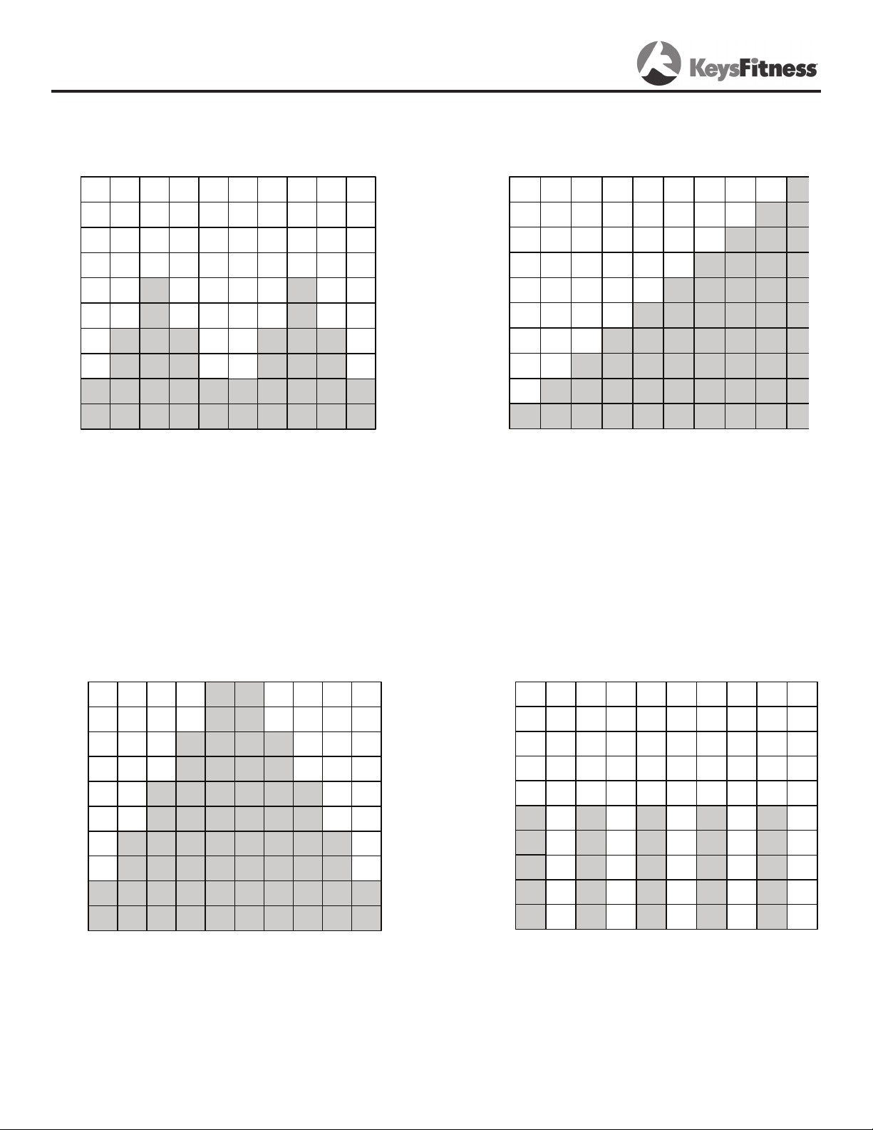
PROGRAM PROFILES
P7 - Each time segment will last 1
minute, and will either increase or
decrease the incline. This program will
repeat this cycle until programmed
time is accomplished.
P9 - Each time segment will last 1
minute, and will increase or decrease
incline. This program will repeat
this cycle until programmed time is
accomplished.
P8 - Each time segment will last 1
minute, and will increase incline. This
program will repeat this cycle until
programmed time is accomplished.
P11 - Each time segment will last 1
minute, and will increase or decrease
incline. This will alternate between
5% and 0% Incline. This program will
repeat this cycle until programmed
time is accomplished.
17
Page 18
Console Instructions
INTERVAL 2
10
9
8
7
6
5
4
3
2
1
0
ESC ALATING INTERVAL
10
9
8
7
6
5
4
3
2
1
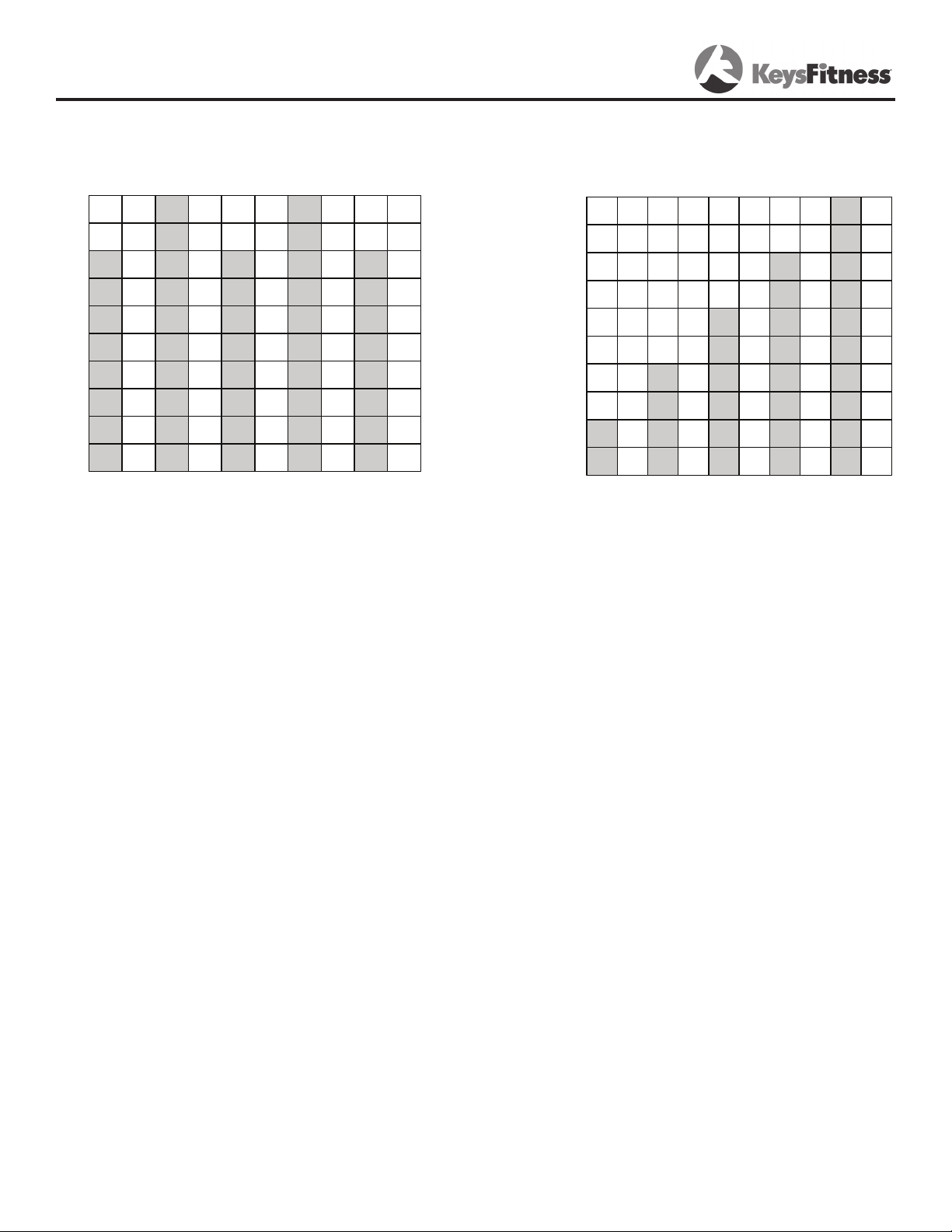
P12 - Each time segment will last 1
minute, and will increase or decrease
incline. This program will alternate
between 8%, 0%, and 10%. This
program will repeat this cycle until
programmed time is accomplished.
P13 - Each time segment will last 1
minute, and will increase or decrease
incline. This program will alternate
between 2%, 0%, 4%, 0%, 6%, 0%,
8%, 0%, 10%, and 0%. This program
will repeat this cycle until programmed
time is accomplished.
18
Page 19
Monitoring Your Heart Rate
Monitoring Your Heart Rate
To obtain the greatest cardiovascular benefits from your exercise workout, it is important to
work within your target heart rate zone. The American Heart Association (AHA) defines this target as 60%-75% percent of your maximum heart rate.
Your maximum heart rate may be roughly calculated by subtracting your age from 220. Your
maximum heart rate and aerobic capacity naturally decreases as you age. This may vary from
one person to another, but use this number to find your approximate effective target zone. For
example, the maximum heart rate for an average 40 year-old is 180 bpm. The target heart
rate zone is 60%-75% of 180 or 108-135 bpm. See Fitness Safety below.
Before beginning your workout, check your normal resting heart rate. Place your fingers lightly
against your neck, or against your wrist over the main artery. After finding your pulse, count
the number of beats in 10 seconds. Multiply the number of beats by six to determine your
pulse rate per minute. We recommend taking your heart rate at these times; at rest, after
warming up, during your workout and two minutes into your cool down, to accurately track
your progress as it relates to better fitness.
During your first several months of exercising, the AHA recommends aiming for the lower part
of the target heart rate zone-60%, then gradually progressing up to 75%.
According to the AHA, exercising above 75% of your maximum heart rate may be too strenuous unless you are in top physical condition. Exercising below 60% of your maximum will result
in minimal cardiovascular conditioning.
Check your pulse recovery rate – If your pulse is over 100 bpm five minutes after you stop
exercising, or if it’s higher than normal the morning after exercising, your exertion may have
been too strenuous for your current fitness level. Rest and reduce the intensity next time.
Fitness Safety The target heart rate chart indicates average rate zones for different ages. A
variety of different factors (including medication, emotional state, temperature and other conditions) can affect the target heart rate zone that is best for you. Your physician or health care
professional can help you determine the exercise intensity that is appropriate for your age and
condition.
(MHR) = Maximum Heart Rate
(THR) = Target Heart Rate
220 - age = maximum heart rate (MHR)
MHR x .60 = 60% of your maximum heart rate.
MHR x .75 = 75% of your maximum heart rate.
For example, if you are 30 years old, your calculations will be as
follows:
220 - 30 = 190
190 x .60 = 114 (low end or 60% of MHR)
190 x .75 = 142 (high end or 75% of MHR)
30 year-old (THR) Target Heart Rate would be 114-142
See Heart Rate Table (on next page) for additional calculations.
19
Page 20
Monitoring Your Heart Rate
TARGET HEART RATE ZONE
100%
Serious
athletic
training range
85%
Cardiovascular
conditioning
range
75%
Fat burning
range
60%
200
170
150
120
195
166
146
117
190
162
143
114
185
157
139
111
180
153
135
108
175
149
131
105
170
145
128
102
165
140
124
99
160
136
120
96
155
132
116
93
20 25 30 35 40 45 50 55 60 65
AGE
20
Page 21
Workout Information
Frequency, Intensity, Time, Target Heart Rate Zone
The exercise practices include four major variables: frequency, intensity, time, target heart rate
zone. A continuous workout will help to improve your cardiovascular functions and increase the
ability of your muscles to obtain the oxygen and nutrition. A good workout provides a greater
advantage to extend the endurance of muscle and body flexibility.
Frequency: How Often Should You Exercise
Three to five times a week is highly suggested to improve your cardiovascular and muscle fitness.
Intensity: How Hard Should You Exercise
The intensity of an exercise is reflected in your heart rate. Exercise must be sufficient to
strengthen your heart muscle and condition your cardiovascular system. Only your doctor or
an authorized coach can prescribe the target training heart range appropriate for your particular
needs and physical condition.
Start with an exercise that stimulates you to breathe more deeply. Alternate periods of moderate and easy exercise to help your body adapt to new levels of exertion without unnecessary
strain. The inability to maintain a smooth, rhythmic motion is a sign that your pace and/or your
elevation is too high . If you feel out of breath before you have exercised 12 minutes, you are
probably overdoing it.
As your fitness level improves, you will need to increase your workload to reach your target
heart rate. The first increase may be necessary after two to four weeks of regular exercise.
Never exceed your target heart rate zone.
Weight Management
Consistent aerobic exercise will help you change your body composition by lowering your percentage of body fat. For weight control, how long and how often you exercise is more important
than how hard you exercise.
Exercise at least four to five times a week.
Reach and maintain 60-75% of your maximum heart rate with moderate exercise.
Exercise for 30-45 minutes at 60-65% of your target heart rate.
Here are some tips to achieve your weight management goal.
Consume most of your dietary calories at breakfast and lunch, and eat a light dinner.
Do not eat anything near the bedtime.
Moderate exercise will help suppress your appetite.
Take regular breaks and rests to help increase metabolism.
Warning!
If you have any questions or concerns about your target heart rate, consult your physician.
Medications may affect your heart rate. Stop exercise if: you feel faint or dizzy, acute illness
(cold or fever), any pain or tightness in your chest, an irregular heartbeat, of if you exceed
your maximum heart rate set by your physician.
21
Page 22
Workout Information
Exercise Practice Procedures
Warm-Up Workout Cool Down
A good warm-up will help you perform better and will decrease the aches and pains. The warmup prepares your muscles for exercise and allows your oxygen supply to ready itself for what is
to come. Experience tells us that muscles perform best when they are warmer than normal body
temperature. This normally takes about 5-10 minutes when you begin to perspire on your brow
and breathe more deeply.
Note: The older you are, the longer your warm-up period should be.
Workout: Brisk and Rhythmic Exercise
A workout trains your heart, lungs, and muscles to be more efficient. Increase exercise in
response to your heart rate to train and strengthen your cardiovascular system. Concentrate on
moving your arms and legs smoothly. Walking naturally and avoid jerking motions like pulled
muscles, sprained joints, and loss of balance.
If you cannot sustain 12 continuous minutes in your target heart rate zone, then, exercise
several times a day to get into habit. Try to reach and maintain 60-65% of your maximum
heart rate. Alternate exercise with periods of rest until you can sustain 12 continuous minutes
of exercise at 60-65% of your maximum heart rate. Best start with a target 3-4 minutes, then,
increase it gradually.
If you can sustain 12 but not 20 continuous minutes of exercise in your target heart rate
zone:
Exercise 3-5 days a week. Rest at least two days per week.
Try to reach and maintain 65-70% of your maximum heart rate with moderate rhythmic
exercises.
Begin with 12 continuous minutes. Increase your time by one to two minutes per week
until you can sustain 20 continuous minutes.
If you can sustain 20 minutes continuously in your target heart rate zone, begin to increase the
length and intensity of your workout:
Exercise 4-6 days a week or on alternate days.
Try to reach and maintain 70~85% of your maximum heart rate with moderate to some-
what hard exercise.
Exercise 20-30 minutes.
WARNING: These strategies are intended for average healthy adults. If you have pain or tightness in your chest, an irregular heartbeat, shortness of breath or you feel faint or have any discomfort when you exercise, STOP. Consult your physician before continuing. Remember, every
workout should begin with warmup and finished with cool down.
Cool down: Slow and Relaxed Exercise
The cool down allows your body’s cardiovascular system to gradually return to normal and
should be roughly 5-10 minutes. Lower your exercise intensity gradually, and when your heart
rate has returned below 110 beats per minutes, you can end your workout.
22
Page 23
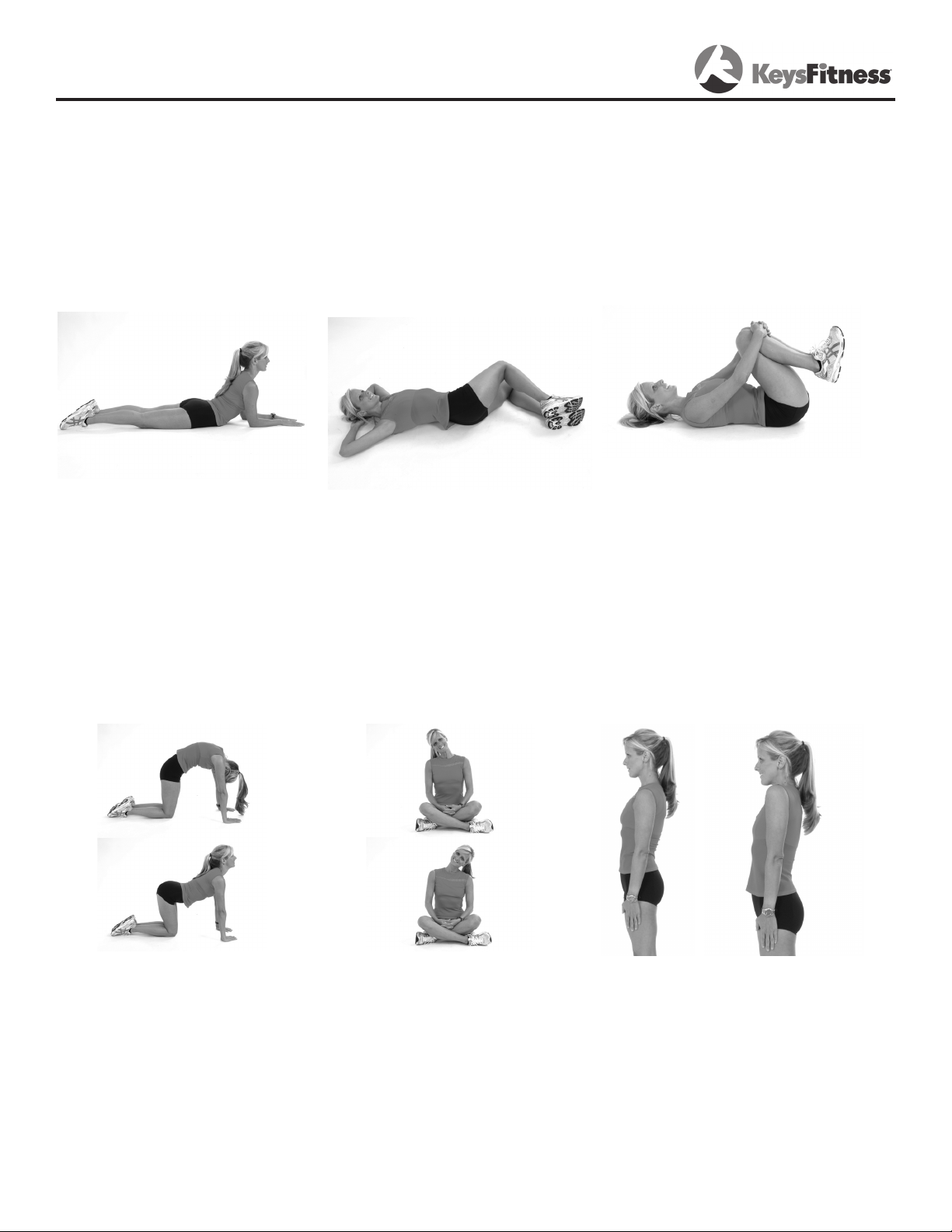
Warm Up Exercises
EXERCISE GUIDELINES
WARNING! Before beginning this or any exercise program, you should consult your physician.
This is especially important for individuals over the age of 35 or individuals with pre-existing
health problems.
Flexibility is a key to fitness. Stretch all major muscle groups at least two to three times per
week after a 5 to 10 minute warmup. Stretch just to the point of a gentle tug. If you have
back, joint, or other health problems, talk to your doctor first.
Prone on Elbows
Lie on your stomach with
your feet together. Rest
on your forearms with your
elbows directly under your
shoulders. Relax lower back
and abdomen into oor. Hold
for 30-60 seconds or until
muscles feel looser.
Supline Lumbar Rotation
Lie on your back with your
knees bent. Keeping your
knees together and your shoul-
ders against the oor, roll your
knees to one side until you feel
a stretch in your back or hip.
Hold for 30-60 seconds or until
muscles feel looser. Repeat on
opposite side.
Knees to Chest
Lie on your back. Bend your
knees, and lift your feet off the
oor. Grasp your knees with
your arms and pull your knees
toward your chest. Hold for 20
seconds. Repeat three to ve
times.
Cat and Camel
Rest on your hands and
knees. Round your back by
contracting your abdominal
muscles and tucking in your
pelvis; hold for ve seconds.
Then allow your back to sag
toward the oor as you lift
your chest and head; hold
for ve seconds. Repeat the
combination 10 times
Cervical Side Bends
Tilt your head gently toward
one shoulder, keeping your
shoulders level and your face
pointed straight ahead. Hold
for ve seconds, then tilt your
head toward the other shoulder
and hold for ve seconds. Repeat ve times on each side.
Shoulder Circles
In a smooth, continuous motion, make a circle with your
shoulders: Raise them up
towards your ears, pull them
together behind you, lower
them to a resting position,
then roll them forward. Repeat
10 times.
23
Page 24
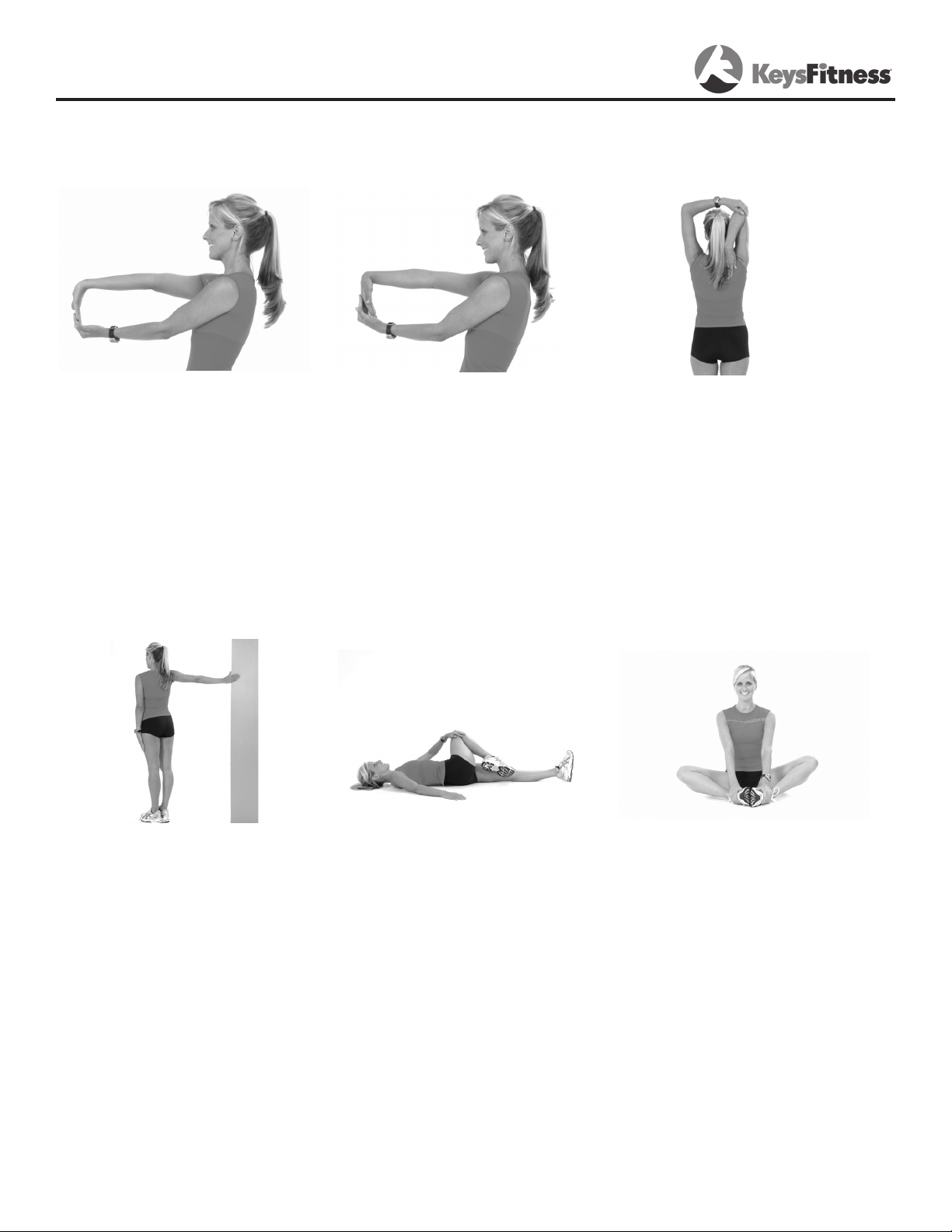
Warm Up Exercises
Wrist Extensor
Extend your right arm in front
of you with your palm up and
your elbow straight. Point
your ngertips toward the
oor by bending at the wrist.
Using your left hand, pull the
back of your right hand to-
ward you gently. Hold for 20
seconds; repeat three to ve
times with each arm.
Triceps Stretch
Place your right hand behind
your head, palm facing your
head. With your left hand,
grasp your right elbow and
pull downward until you feel
a stretch in the back of your
right arm. Hold for 20 seconds; repeat three to ve
times with each arm.
Piriformis Stretch
Lie on your back. Bend your
right knee and lift it halfway
to your chest. Grasp your
knee with your left hand and
pull it toward your left shoulder, keeping both buttocks
against the oor. Hold for 20
seconds; repeat three to ve
times with each leg.
Groin (Adductors) Stretch
Sitting with your back
straight, bring the soles of
your feet together. Let your
knees lower toward the oor.
Hold for 30-60 seconds or
until muscles feel looser.
One-Arm Pectoralis Stretch
Stand against an immobile
structure like a wall or a tree.
While facing the wall, raise
your right hand out to your
side at chest height, palm
against the wall. Turn your
body toward the left, away
from the wall and your extended arm, until you feel a
stretch. Hold for 20 seconds;
repeat three to ve times with
each arm.
WARNING! Before beginning this or any exercise program, you should consult your physician.
This is especially important for individuals over the age of 35 or individuals with pre-existing
health problems.
Wrist Flexor
Extend your right arm in front
of you, palm down, elbow
straight. Point your ngertips
toward the oor by bending
at the wrist. Using your left
hand, pull your right palm to-
ward you gently. Hold for 20
seconds; repeat three to ve
times with each arm.
24
Page 25
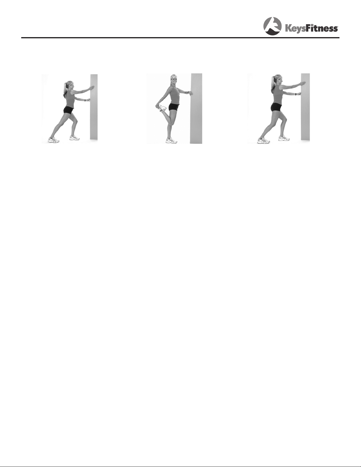
Warm Up Exercises
Standing Quadriceps Stretch
Steady yourself with one hand.
With the other, grab outside leg
at ankle, keeping body straight
from knee to hip. Gently pull
foot up and towards the buttocks until you feel a stretch
along the front of the thigh.
Thigh should be pulled straight
back and not drift to outside.
Hold 20-30 seconds. For variation, grab opposite ankle (i.e.,
grab right ankle with left hand).
Do two to three repetitions per
leg.
Achilles Stretch
Face the wall with your left
foot ahead of your right, toes
straight ahead. Bend both
knees, press your hips forward,
and lean into the wall. Keep
both heels down and both
knees in line with your feet.
Hold for 20 seconds; repeat
three to ve times with each
leg.
Calf Stretch
Face a solid structure such as
a wall with your left foot ahead
of your right, toes straight
ahead. Bend your left knee,
press your hips forward, and
lean into the wall. Keep both
heels down, your right leg
straight, and you left knee
over your ankle. Hold for 20
seconds; repeat three to ve
times with each leg.
WARNING! Before beginning this or any exercise program, you should consult your physician.
This is especially important for individuals over the age of 35 or individuals with pre-existing
health problems.
25
Page 26

Calibration Sequence
Do not attempt to calibrate the treadmill unless an Error Code is present. See Error
Messages (page 29).
Our treadmill is equipped with a software package that will perform a calibration sequence
unique to your specific model number.
Please perform the following steps to calibrate the Keys Fitness KF-3.0T Treadmill.
1. Unplug power cord from outlet strip.
2. Attach Safety Key to console.
3. Plug power cord into outlet strip.
4. Initiate calibration sequence. To do so, press the Program Up, Program Down, and the
Program button simultaneously for about 3 seconds.
5. CL11 should appear in the Time window. Press Pause.
Note: During the calibration sequence, the Time window will display which step you are at
in the process (C21, C22, C23 and so on).
6. CL21: MPH or KPH will be flashing in the Time window, pressing the Speed +/ - button will
toggle options. Choose MPH (KPH), press Program.
7. CL22: 8, 10, or 12 (13, 16, or 20 in KPH mode) will be displayed in the Speed window,
pressing the Speed +/ - button will toggle options. Choose 12 (or 20 for KPH mode), press
Program.
8. CL23: FFF, UUU, or HHH will be displayed in the Speed window, pressing the Speed +/ button will toggle options. Choose UUU, press Program.
9. CL24: 111 or 222 will be displayed in the Speed window, pressing the Speed +/ - button
will toggle options. Choose 222, press Program.
10. CL25: “nHr” will be displayed in the Speed window, press Program.
11. CL26: OPA or OPI will be displayed in the Speed window, pressing the Speed +/ - button
will toggle options. Choose OPA, press Program.
12. CL27: Blank (nothing), “a”, “b”, “c”, “d” or “e” will be displayed in the Incline window,
pressing the Speed +/ - button will toggle options. Choose “E”, press Program.
13. CAL/DIST window will display “55”. Press Start / Stop. “E” will display in CAL/DIST window.
14. At this time, make sure you are not standing on the walking belt, as the machine will automatically initiate belt movement and run through a complete calibration and diagnostic routine. Press Program. Belt will begin to move. Unit will begin self-calibration.
15. When Speed and Incline calibration has finished, press Power button twice, display should
be blank, and treadmill should be ready for use.
To avoid possible damage to the treadmill and the possibility of injury, do not operate the treadmill until the problem is corrected. Call Keys Fitness Customer Service at
888-340-0482 if problem persists.
Change to MPH or KPH
Your treadmill will operate in British Units (miles per hour) or International Units (kilometers
per hour). All treadmills are calibrated at the factory for British Units (miles per hour). To
change the display to read in kilometers, follow the steps described here:
1. Turn power OFF on the console. Attach the magnet safety key to the console.
2. Press the Program Up, Program Down, and the Enter button simultaneously for about 3 sec-
onds.
3. CL11 should appear in the TIME window.
4. Pressing the SPEED +/- button will activate your choice. Press the POWER button to accept.
26
Page 27
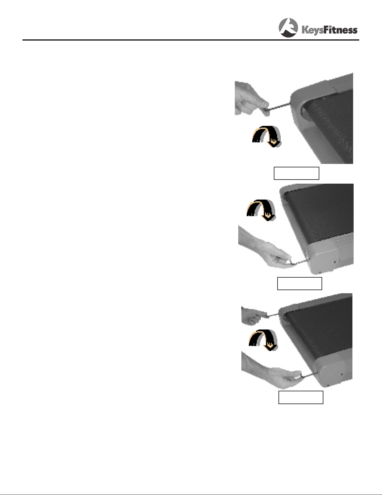
Belt Adjustment
WARNING! Do not over-tighten rollers! This will
cause premature roller bearing failure!
Belt adjustment and tension performs two functions:
adjustment for tension and centering. Your new treadmill comes pre-adjusted from the factory for tension and
centering. Please follow the procedures below if the belt
shifts to the left or right while walking:
WALKING BELT IS SHIFTING TO THE LEFT
(Diagram 1)
First, turn treadmill on to run at 1 mph. Using the hex key
provided, turn the left rear roller adjustment bolt ¼ turn in
the clockwise direction. Next, run the treadmill at 2.5 mph.
You should see the belt start to correct itself by moving
back toward the center. Repeat the above procedure until
the walking belt is centered. It may be necessary to set
walking belt tension once you have completed this procedure if the belt feels like it is slipping while walking. Refer
below to the “Walking Belt Slipping” instructions.
Diagram 1
WALKING BELT IS SHIFTING TO THE RIGHT
(Diagram 2)
First, turn the treadmill on to run at 1 mph. Using the hex
key provided, turn the right rear roller adjustment bolt
¼ turn in the clockwise direction. Next, run the treadmill
at 2.5 mph. You should see the belt start to correct itself,
moving back toward the center. Repeat the above procedure until the walking belt is centered. It may be necessary to set walking belt tension once you have completed
this procedure if the belt feels like it is slipping while walking. Refer below to the “Walking Belt Slipping” instructions.
WALKING BELT IS SLIPPING DURING USE (Diagram 3)
First, unplug the power cord from the surge protector.
Using the hex key provided, turn both left and right rear
roller adjustment bolts the same distance, usually a ¼
turn, in the clockwise direction. Plug the power cord back
into the surge protector and run the treadmill at 2.5 mph.
You should now walk on the belt to determine if the belt is
still slipping. Repeat the above procedure until the walking
belt is not slipping. The tension should be just tight enough
not to slip.
Diagram 2
Diagram 3
Note: Turning the hex key clockwise brings the rear roll-
ers and belt towards you.
Turning the hex key counter clockwise pushes the rear
roller and belt away from you.
27
Page 28
Maintenance Instructions
WARNING! Before performing any maintenance to your treadmill, always unplug the
power cord from the surge protector.
CLEANING: Routine cleaning of your unit will extend the life of your unit.
WARNING! To prevent electrical shock, be sure the power to the treadmill is OFF and the unit is
unplugged from the wall electrical outlet before attempting any cleaning or maintenance.
AFTER EACH WORKOUT: Wipe off the console and other treadmill surfaces with a clean,
water dampened soft cloth to remove excess perspiration. USE NO CHEMICALS.
WEEKLY: Use of a treadmill mat is recommended for ease of cleaning. Dirt from your shoes
contacts the belt and eventually makes it to underneath the treadmill. Vacuum underneath
treadmill once a week.
DECK LUBRICATION: The walking belt has been pre-lubricated at the factory. However, it is
recommended that the walking board be checked periodically for lubrication to ensure optimal
treadmill performance. Every 30 days or 30 hours of operation, lift the sides of the walking belt
and feel the top surface of the walking board as far under as you can reach. If you feel signs
of silicone, no further lubrication is required. If it feels dry to the touch, lubrication is needed.
Keys Fitness recommends “Lube N Walk” for cleaning and lubricating the treadmill belt and
deck. Ask your retailer or call Keys Fitness at 888-340-0482.
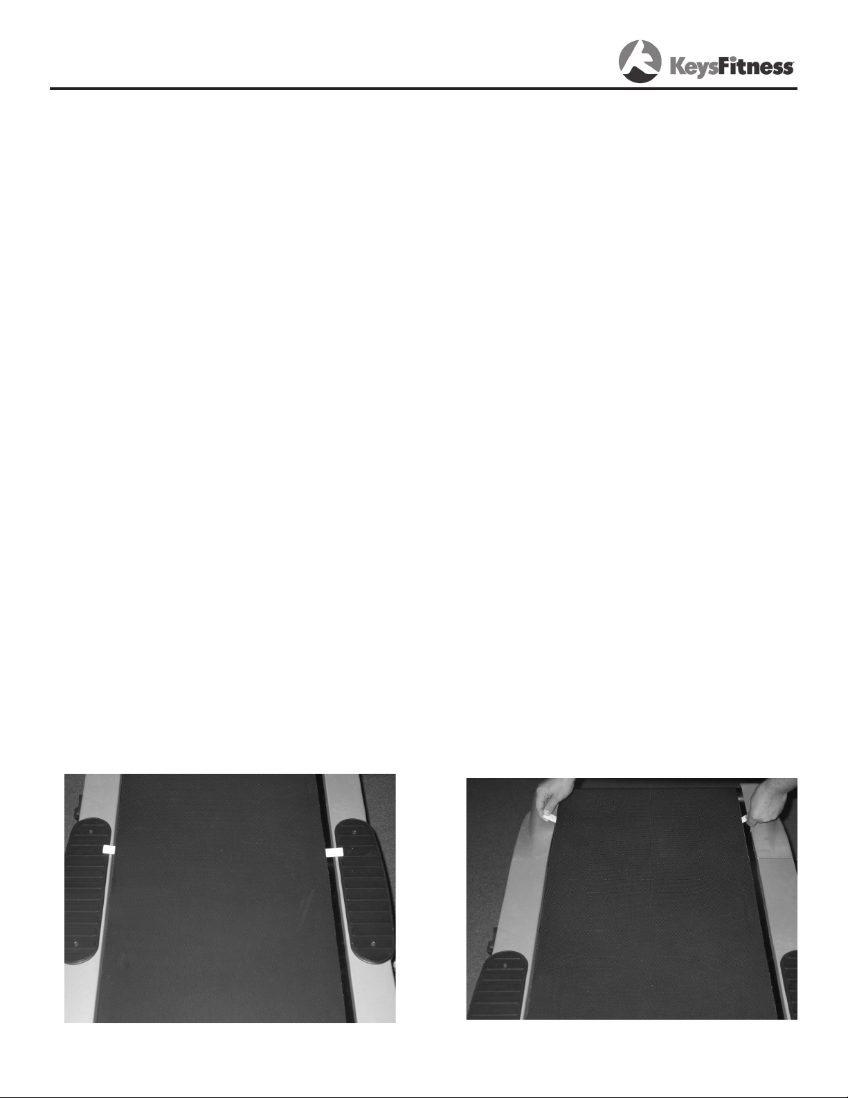
TO APPLY LUBRICANT TO THE WALKING BOARD
1.) Take foam wand applicator, without lube, and insert it in between the walking belt and deck,
exposing the two plastic tabs at either end of the walking belt. Take both tabs and run the
wand back and fort along the entire length of your deck. Remove the applicator and prepare for
lubrication.
2) Apply about a dime's worth of lubrication onto the side of the applicator wand hat was not
used for removing dirt and debris (step 1). You can add more or less lubricant, depending on
your lubrication schedule.
3) Insert the wand between the walking belt and deck, exposing the two white plastic tabs at
either end of the walking belt.
4) Take both of the tabs and run the wand back and forth along the entire length of your deck.
You are done until your next scheduled lubrication date.
5) Allow the silicone to ‘set’ for one minute before using the treadmill.
WARNING: Do not over-lubricate the walking board. Excess lubricant should be wiped
off with a clean towel.
28
Page 29
Error Messages
Treadmill Error Messages.
Your treadmill is equipped with a software package that enables error messages to be
displayed when there is a problem. The following error codes will be displayed in the console
display windows.
Safety Interlock Error Messages
SI 1 - Safety key missing, replace and try again.
SI 2 - Over voltage protection trip. Notify Keys Fitness Customer Service.
Other Error Messages
E11 - Lack of speed feedback data from belt motor. Attempt calibration. See Calibration
Sequence section on page 26 of this Owners Manual for detailed information.
E22 - Under Speed condition detected from the belt motor. Attempt calibration. See Calibration
Sequence section for detailed information.
E33 - Over Speed condition detected from the belt motor. Attempt calibration. See Calibration
Sequence section for detailed information.
E44 - Lodged key detected at power up, Notify Keys Fitness Customer Service.
To avoid possible damage to the treadmill and the possibility of injury, do not operate the treadmill until the problem is corrected. Call Keys Fitness Customer Service at
888-340-0482.
29
Page 30

Troubleshooting Guide
Treadmill will not start.
1. Is the Safety Key inserted into the treadmill Console?
2. Make sure the power cord is plugged into a surge protector, the surge protector is plugged
into a properly grounded outlet, and the surge protector is turned on. (Refer to “Power
Requirements” on page 11.)
3. Check the circuit breaker located on the front of the treadmill. If the switch protrudes, it
has tripped. Wait five minutes and then press the switch back in.
4. Check the house electrical breaker box and the circuit breaker for the room where the
treadmill is located. If it has tripped, reset or have an electrician replace the breaker in
home.
5. Have an electrician check to ensure there is adequate voltage at the outlet.
Treadmill loses power during use.
1. Check the circuit breaker located on the front of the treadmill. If the switch protrudes, it has
tripped. Wait five minutes and then press the switch back in.
2. Check the house electrical breaker box and the circuit breaker for the room where the
treadmill is located. If it has tripped, reset or have an electrician replace the breaker in
home.
3. If the treadmill will not operate, please call Keys Fitness Customer Service at 888-340-0482.
Treadmill walking belt slows during use.
1. Check to make sure the treadmill is securely plugged into an UL-listed surge protector, rated
at 15 amps, with a 14-gauge cord of five feet or less and the surge protector is securely
plugged into the outlet.
2. If treadmill will not operate, please call Keys Fitness Customer Service at 888-340-0482.
Treadmill walking belt slips or is not centered on rear roller.
1. Refer to “Belt Adjustment” section on page 27.
2. Need help? Call Keys Fitness Customer Service at 888-340-0482.
Treadmill Error Messages.
Your treadmill is equipped with a software package that enables error messages to be
displayed when there is a problem.
To avoid possible damage to the treadmill and the possibility of injury, do not operate the treadmill until the problem is corrected. Call Keys Fitness Customer Service at
888-340-0482, or see “Error Messages” on page 29 of this Owner’s Manual.
30
Page 31

Parts List
Ref # Part # Description Qty Ref # Part # Description Qty
UAB2 402-00225 WASHER, SIDE RAIL, HT-740T/KF-3.0T 8 UAS28 406-00261 FOAM TUBE, HT-740T/KF-3.0T 2
UAJ35 402-00260 SCREW M4*10, HT-740T/KF-3.0T 1 UAS29 406-00262 COVER, LEFT PROTECTION, HT-740T/KF-3.0T 1
UAW1 402-00262 SLEEVE TUBE, HT-740T/KF-3.0T 4 UAS30 406-00263 COVER, RIGHT PROTECTION, HT-740T/KF-3.0T 1
UAW8 402-00263 #6 ALLEN WRENCH, HT-740T/KF-3.0T 1 UAS31 406-00264 COVER, LEFT INNER, HT-740T/KF-3.0T 1
UAW9 402-00264 #5 ALLEN WRENCH, HT-740T/KF-3.0T 1 UAS32 406-00265 COVER, RIGHT INNER, HT-740T/KF-3.0T 1
UAW10 402-00265 WRENCH W/SCREW DRIVER, HT-740T/KF-3.0T 1 UAS33 406-00266 RUBBER PAD, HT-740T/KF-3.0T 8
UAS21 402-00266 FLAT WASHER, HT-740T/KF-3.0T 4 UAS34 406-00267 PIN BAR, HT-740T/KF-3.0T 1
UAD5 402-00267 SAFETY KEY, HT-740T/KF-3.0T 1 UAS35 406-00268 AXLE CAP, HT-740T/KF-3.0T 1
UAD20 402-00268 MAGNETIC RING, HT-740T/KF-3.0T 1 UAD15 406-00269 OVERLOADING PROTECTOR, HT-740T/KF-3.0T 1
U4J1 402-00270 BOLT M10*65, HT-760T/KF-3.0T 1 U4S3 406-00274 FOAM TUBE, HT-760T/KF-3.0T 1
U4J2 402-00271 BOLT M10*45, HT-760T/KF-3.0T 1 UAS25 406-00276 WHEEL, HT-760T/KF-3.0T 2
U4J3 402-00272 BOLT M8*30, HT-760T/KF-3.0T 2 U2S5 406-00283 INSERT, KF-3.0T 1
U4J4 402-00273 BOLT M8*26, HT-760T/KF-3.0T 5 U4S10 406-00284 CONNECTION PLATE, LEFT, KF-3.0T 1
U4J5 402-00274 BOLT M10*25, HT-760T/KF-3.0T 12 U4S11 406-00285 CONNECTION PLATE, RIGHT, KF-3.0T 1
U4J6 402-00275 BOLT M8*45, HT-760T/KF-3.0T 4 U4W13 406-00286 SPEAKER GRILL, LEFT, KF-3.0T 1
U4J7 402-00276 BOLT M8*52, HT-760T/KF-3.0T 7 U4W14 406-00287 SPEAKER GRILL, RIGHT, KF-3.0T 1
U4J8 402-00277 BOLT M10*145, HT-760T/KF-3.0T 1 U4D24 407-00038 SPEAKER, KF-3.0T 2
U4J9 402-00278 BOLT M8*20, HT-760T/KF-3.0T 2 U4D30 407-00039 AMPLIFYING BOARD, KF-3.0T 1
U4J10 402-00279 BOLT M10*30, HT-760T/KF-3.0T 4 UAD2 407-00133 BOARD, HEARTBEAT, HT-740T/KF-3.0T 1
U4J11 402-00280 BOLT M6*25, HT-760T/KF-3.0T 8 UAD4 407-00135 PULSE SENSOR, HT-740T/KF-3.0T 2
U4J12 402-00281 BOLT M6*40, HT-760T/KF-3.0T 4 UAD14 407-00136 CONTROL BOARD, HT-740T/KF-3.0T 1
U4J13 402-00282 BOLT M8*65, HT-760T/KF-3.0T 2 U2D1 407-00143 CONSOLE, KF-3.0T 1
U4J14 402-00283 BOLT M8*40, HT-760T/KF-3.0T 1 UAD23 407-00138 SPEED INCLINE PCB, HT-720T, HT-740T/KF-3.0T 2
U4J15 402-00284 SCREW M6*16, HT-760T/KF-3.0T 4 UAD16 408-00062 BREAKER, HT-740T/KF-3.0T 1
U4J16 402-00285 SCREW M6*12, HT-760T/KF-3.0T 2 U2W2 409-00019 FRONT ROLLER, HT-740T/KF-3.0T 1
U4J17 402-00286 SCREW M5*6, HT-760T/KF-3.0T 17 U2W3 409-00020 REAR ROLLER, HT-740T/KF-3.0T 1
U4J18 402-00287 SCREW M5*10, HT-760T/KF-3.0T 4 U1W7 410-00068 GAS SHOCK, HT-740T/KF-3.0T 2
U4J19 402-00288 SCREW ST2.9*9.5, HT-760T/KF-3.0T 4 UAW11 410-00069 COMPRESSING SPRING, HT-740T/KF-3.0T 1
U4J20 402-00289 SCREW ST2.9*6.5, HT-760T/KF-3.0T 48 UAW12 410-00070 MOUNTING PART, HT-740T/KF-3.0T 1
U4J21 402-00290 SCREW ST4.2*12, HT-760T/KF-3.0T 16 UAD19 412-00034 INCLINE MOTOR, HT-740T/KF-3.0T 1
U4J22 402-00291 SCREW ST2.9*15, HT-760T/KF-3.0T 4 U4D18 412-00035 DC MOTOR, 3.0HP HT-760T/KF-3.0T 1
U4J23 402-00292 SCREW ST3.5*35, HT-760T/KF-3.0T 2 U2D6 413-00094 WIRE, AC SINGLE 6, HT-740T/KF-3.0T 1
U4J24 402-00293 SCREW ST4.2*12, HT-760T/KF-3.0T 6 U2D7 413-00095 WIRE, AC SINGLE 7, HT-740T/KF-3.0T 1
U4J25 402-00294 SCREW ST4.2*9.5, HT-760T/KF-3.0T 24 UAD8 413-00096 WIRE, AC SINGLE 8, HT-740T/KF-3.0T 1
U4J27 402-00296 FLAT WASHER M10, HT-760T/KF-3.0T 15 U2D9 413-00097 WIRE, INCLINE MOTOR CONNECTION 1
U4J28 402-00297 FLAT WASHER M8, HT-760T/KF-3.0T 29 UAD10 413-00098 UPPER, COMPUTER WIRE, HT-740T/KF-3.0T 1
U4J29 402-00298 FLAT WASHER M5, HT-760T/KF-3.0T 4 UAD11 413-00099 LOWER, COMPUTER WIRE, HT-740T/KF-3.0T 1
U4J30 402-00299 SPRING WASHER M8, HT-760T/KF-3.0T 6 UAD12 413-00100 MIDDLE, COMPUTER WIRE, HT-740T/KF-3.0T 1
U4J31 402-00300 LOCK NUT M8, HT-760T/KF-3.0T 8 UAD13 413-00101 ADAPTOR, HT-740T/KF-3.0T 1
U4J32 402-00301 LOCK NUT M10, HT-760T/KF-3.0T 1 UAD17 413-00102 POWER CABLE, HT-740T/KF-3.0T 1
U4J33 402-00302 SCREW M5*12, HT-760T/KF-3.0T 2 UAD21 413-00103 REED SWITCH, HT-740T/KF-3.0T 1
U4J34 402-00303 LOCK NUT M6, HT-760T/KF-3.0T 8 U4D25 413-00112 AMPLIFYING, TOP SPEAKER WIRE, KF-3.0T 1
U2S27 404-00021 BELT, HT-760T/KF-3.0T 1 U4D26 413-00113 AMPLIFYING, MIDDLE SPEAKER WIRE, KF-3.0T 1
U2S4 404-00023 RUNNING BELT, KF-3.0T 1 U4D27 413-00114 AMPLIFYING, BOTTOM SPEAKER WIRE, KF-3.0T 1
UAW6 406-00239 SLEEVE, HT-740T/KF-3.0T 2 U4D28 413-00115 MP3 WIRE CONNECT, KF-3.0T 1
UAS1 406-00240 PLASTIC FIXING BRACKET, HT-740T/KF-3.0T 1 U4D29 413-00116 MP3 CONNECTER, KF-3.0T 1
UAS2 406-00241 END CAP, HT-740T/KF-3.0T 2 U4D31 413-00117 AMPLIFYING ADAPTOR, KF-3.0T 1
UAS6 406-00244 COVER, COMPUTER TOP, HT-740T/KF-3.0T 1 U4D32 413-00118 AMPLIFYING WIRE , KF-3.0T 1
UAS7 406-00245 COVER, COMPUTER BOTTOM, HT-740T/KF-3.0T 1 U4D33 413-00119 AMPLIFYING WIRE 1, KF-3.0T 1
U1S8 406-00246 COVER, LEFT MOTOR LIGHT, HT-740T/KF-3.0T 1 U1G1 419-00038
T
UBE, RUNNING BOARD, HT-740T/KF-3.0T 1
U1S9 406-00247 COVER, RIGHT MOTOR LIGHT, HT-740T/KF-3.0T 1 UAB1 419-00039 BOARD, SIDE RAIL FIXED, HT-740T/KF-3.0T 4
UAS12 406-00248 COVER, LEFT END, HT-740T/KF-3.0T 1 U1W4 419-00040 AXLE, HT-740T/KF-3.0T 1
UAS13 406-00249 COVER, RIGHT END, HT-740T/KF-3.0T 1 U1W5 419-00041 LIMIT AXLE, HT-740T/KF-3.0T 1
UAS14 406-00250 COVER, END CAP, HT-740T/KF-3.0T 2 U2S15 419-00045 SIDE RAIL, HT-3.0T 2
U1S16 406-00251 MOTOR COVER, HT-740T/KF-3.0T 1 U2D22 419-00046 RUNNING BOARD, KF-3.0T 1
U1S17 406-00252 MOTOR COVER FRONT CAP, HT-740T/KF-3.0T 1 UAT6 423-00088 LEFT HANDLEBAR, HT-740T/KF-3.0T 1
UAS18 406-00253 RING SHAPE CAP, HT-740T/KF-3.0T 2 UAT7 423-00089 RIGHT HANDLEBAR, HT-740T/KF-3.0T 1
UAS19 406-00254 MOVING WHEEL, HT-740T/KF-3.0T 4 U1T8 423-00090 FRAME, COMPUTER, HT-740T/KF-3.0T 1
UAS20 406-00255 MOVING WHEEL TUBE CAP, HT-740T/KF-3.0T 2 U4T3 423-00101 MOTOR FRAME, HT-760T/KF-3.0T 1
UAS22 406-00256 CUSHION, HT-740T/KF-3.0T 2 U4T4 423-00102 LEFT UPRIGHT, HT-760T/KF-3.0TE 1
UAS23 406-00257 INNER TUBE CAP, HT-740T/KF-3.0T 4 U4T5 423-00103 RIGHT UPRIGHT, HT-760T/KF-3.0T 1
UAS24 406-00258 PLASTIC BEARING, HT-740T/KF-3.0T 2 U4T11 423-00104 CROSS BAR, HT-760T/KF-3.0T 1
UAS26 406-00259 WHEEL, HT-740T/KF-3.0T 2
KF-3.0T PARTS LIST REV B
31
Page 32
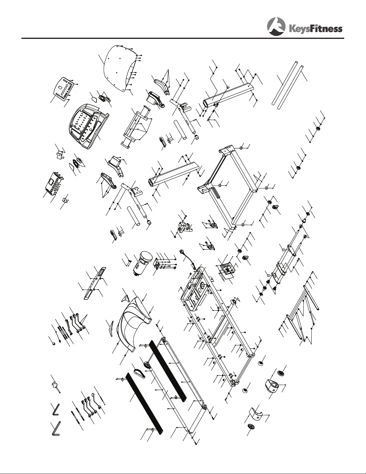
Exploded View
ÆäÓà:
UAT7
U4T5
U1T8
U4T4
U4T3
UAT6
UAB1
U1G1
UAB2
UAB2
UAB2
UAB2
UAB2
UAB2
UAB2
U2W2
U2W3
U1W4
U1W5
UAW6
UAW6
U1W7
U1W7
UAW8
UAW9
UAW10
UAS1
UAS2
UAS2
U2S4
U2S5
UAS6
UAS7
U1S8
U1S9
UAS12
UAS13
UAS14
UAS14
U2S15
U1S16
U1S17
UAS18
UAS21
UAS21
UAS21
UAS21
UAS22
UAS22
UAS23
UAS23
UAS24
UAS24
UAS25
UAS25
UAS26
UAS26
U2S27
UAS28
UAS28
U4J1
U4J2
U4J9
U4J4
U4J4
U4J4
U4J4
U4J5
U4J5
U4J5
U4J5
U4J5
U4J5
U4J6
U4J6
U4J7
U4J7
U4J6
U4J6
U4J8
U4J10
U4J11
U4J11
U4J13
U4J13
U4J15
U4J15
U4J15
U4J15
U4J16
U4J16
U4J18
U4J18
U4J18
U4J18
U4J20
U4J20
U4J25
U4J21
U4J22
U4J23
U4J23
U4J24
U4J24
U4J25
U4J25
U4J25
U4J25
U4J25
U4J25
U4J25
U4J25
U4J25
U4J25
U4J25
U4J25
U4J25
U4J3
U4J7
U4J21
U4J27
U4J27
U4J27
U4J27
U4J27
U4J27
U4J27
U4J27
U4J27
U4J28
U4J28
U4J28
U4J28
U4J28
U4J28
U4J28
U4J28
U4J28
U4J28
U4J28
U4J28
U4J28
U4J30
U4J32
U4J17
U4J33
U2D1
UAD2
UAS29
UAS30
UAS31
UAS32
U4J28
U4J28
UAD4
UAD5
U2D6
U2D7
UAD8
U2D9
UAD10
UAD12
UAD11
UAD13
UAD15
UAD16
UAD17
U4D18
UAD19
UAD20
UAD21
U2D22
UAS33
UAS33
UAS33
UAS33
UAS33
UAS33
UAS33
UAS34
UAS35
UAW11
U4J25
U4J25
U4J31
U4J31
U4J17
U4J29
U4J12
U4J12
U4J19
U4J5
UAJ35
U4J5
U4T11
U4S3
U4J3
U4J7
U4J4
U4J28
U4J28
U4J7
U4J21
UAS19
UAS19
U4J28
U4J31
U4J28
U4J31
UAW1
U4J31
U4J28
UAW1
UAS20
UAW1
UAS20
UAW1
UAS19
U4J28
U4J31
UAS19
U4J37
U4J17
UAD23
U4J28
U4J14
UAW12
U4J17
UAD14
UAD23
U4J17
UAD4
U4W13
U4J20
U4S10
UAJ20
U4D30
U4D24
U4J20
U4W14
U4S11
U4D24
U4D28
U4D27
U4D25
U4D26
U4D29
U4D33
U4D32
U4D31
U4J17
32
Page 33

Warranty Information
Residential and Personal Use Limited Warranty
PLEASE READ THESE WARRANTY TERMS AND CONDITIONS FULLY AND CAREFULLY BEFORE USING YOUR KEYS FITNESS EQUIPMENT. BY
USING THE EQUIPMENT, YOU ARE CONSENTING TO BE BOUND BY THE FOLLOWING TERMS AND CONDITIONS.
Frame: Lifetime Drive Motor: Lifetime Parts: 2 yrs Deck and Belt: 5 Yrs Labor: 1 Yr Speakers: 1 Yr
Missing/Cosmetic Parts: 30 Days
Limited Warranty
This Limited Warranty applies in the United States and Canada to
Products manufactured or distributed by Keys Fitness Products, L.P.
under the Keys Fitness (“Keys”) brand name (as used herein, the
“Product” or “Products”). The warranty period to the original
purchaser is listed above, and commences on the date of original
purchase of the product, unless otherwise authorized by Keys. Keys
warrants that the Product purchased from Keys or from an
authorized Keys Fitness reseller “dealer” (for residential or personal
use only, unless otherwise authorized by Keys in writing), is free
from defects in Materials and Workmanship relevant to the
functionality of the Product at initial startup, under normal use, and
during the applicable warranty period, unless otherwise determined
by Keys.
This warranty ex
cludes expendable parts if the primary cause for a
warranty claim is wear. Expendable parts pertain to components on
the Product that are prone to normal wear and tear. These items
vary by Product, and may include (but not be limited to) hand grips,
skid pads, walking belts, walking decks, poly-v belts, console
overlays, toggle switch/button overlays, (luster free or dull) ekg
plates, decals, and any other items that are not essential to the
operation of the Product, unless otherwise determined by Keys.
This warranty extends only to you, the original purchaser. It is not
transferable to anyone who subsequently purchases (or receives as a
gift) the Product from you. Your sales receipt, showing the
date/place of purchase and serial number (if applicable) of the
Product, is your proof of purchase, and may be required by Keys any
time a warranty parts or service claim is made or if no warranty
record exists for the product.
Exclusive Remedies
During the warranty period listed above, Keys will repair a Product
by correcting any minor issues (either by phone or online support)
that might be causing the Product failure. Should a technical service
and support representative be unable to correct the issue, Keys
may replace the parts (with new parts or at the option of Keys, with
serviceable used parts, that are equivalent to new parts in
performance) that become defective, malfunction, or otherwise fail
to conform to this Limited Warranty under normal use.
Replacement parts shall be warranted for 30 days from the shipment
reception date or through the end of the ‘replaced’ part warranty
period, whichever is longer. Any replacement parts, required past
the warranty period listed above, shall be subject to purchase at
retail price, plus any added shipping and handling charges associated
to the delivery of the part. Note that replacement parts may be
available only through the **lifetime (as defined) of the Product. In
conforming to this warranty, Keys (as the manufacturer) reserves
the right to change manufacturers or vendors of any part to cover
the existing warranty.
Keys may also provide service (if deemed necessary and if applicable)
at no charge to you during (and not to exceed) the service warranty
period listed above, in an attempt to repair the Product. Should the
Product require service at your request or out of the limited warranty
period, Keys can furnish contact information for local (to your area)
Keys authorized service providers. Service quotes, costs, and
scheduling will be strictly dependent on service provider rates and
mutual (consumer/provider) service agreements. Keys is not
responsible for any service repair costs accrued through the use of
authorized Keys service providers dispatched at your request or out
of the limited warranty period (without written consent from Keys),
and beyond the limitations outlined on this warranty.
Replacements and Returns
If after a reasonable number of attempts, a defect has not been
repaired (or the Product is deemed non-repairable by Keys technical
service and support staff), Keys, based on a case by case review,
may opt to replace the Product, or recommend an alternate
resolution, such as a warranty buy-out (Product cost, subject to
deduction of a reasonable charge for usage) or a credit.
Keys, as a manufacturer, reserves the right to replace the Product with
a Factory-Reconditioned Product that meets or exceed standards
comparable to those of the replaced Product.
The warranty covering the replacement Product shall expire on the
date the original warranty for the replaced Product would have expired,
unless otherwise determined by Keys. Note that a non
-defective
Product may not be eligible for return or replacement after 30 days from
date of purchase. If opting to return a non-defective product to Keys, as
the manufacturer, within 30 days from date of purchase (in its original
packaging and with its original proof of purchase), the “customer” shall
be subject to a 15% restocking fee and pre-paid freight charges accrued
as a result of the return, unless otherwise determined by Keys.
Conditions and Restrictions
This warranty DOES NOT (A) cover shipping and handling charges,
export taxes, custom duties and taxes, or any other charges associated
with transportation of the parts or Product, beyond the initial courtesy
period of 60 days from original date of purchase of the Product; (B)
extend to Products not purchased from Keys or from an authorized
Keys reseller; (C) extend to Products purchased from online auction
sites; (D) cover any extended, additional, or third party warranties if
not offered exclusively by Keys in writing; (E) cover Products installed
at fee based facilities/commercial environments (gyms, homes used as
wellness centers, etc.); (F) cover Products installed in light institutional
environments (non fee-based facilities with total Product use time not
exceeding 5 hours daily, to include for example, and not be way of
limitation, fire houses, police departments, rehab centers, hospitals,
clinics, apartment complexes, club houses, etc.); (G) cover service calls
to correct installation, perform maintenance, or instruct owners on how
to use the equipment; or (H) cover a Product on which the serial
number has been purposefully or accidentally defaced or removed and
there is no proof of purchase available (if serial number is applicable),
unless authorized by Keys in writing or otherwise stated on this
warranty.
This Limited Warranty becomes void for Products that have been
damaged or rendered defective as a result of (a) accident, misuse, or
abuse (including but not limited to exceeding the Keys listed, maximum
weight limit); (b) use of parts not manufactured or sold by Keys; (c)
modification of the Product; (d) normal wear and tear; (e) operation on
incorrect power supplies; (f) ***failure to perform (or performing
improper) maintenance; (g) service by anyone other than Keys, or an
authorized Keys warranty service provider; (h) floods, fires,
earthquakes, lightning strikes, power surges, and other unavoidable
acts of nature; (j) residential mis-wires; or (k) incorrect setup,
installation, or assembly. Should any Product (submitted for warranty
parts replacement) be found ineligible under the terms outlined on this
warranty, an estimate for parts purchase (if available) can be furnished
at your request.
*Parts is herein defined exclusively, for all intents and purposes, and
pertaining to this Limited Manufacturer Warranty, as components or Materials
essential to the functionality of the Product.
**Lifetime of a Product, is herein defined exclusively, for all intents and
purposes, and pertaining to this Limited Manufacturer Warranty, as the time
period 7 years beyond the end of production cycle of a Product in question.
*** Includes proper lubrication of the running deck and walk belt area, as
indicated in the owner’s manual.
Disclaimer and Release
EXCEPT AS EXPRESSLY SET FORTH IN THIS WARRANTY, KEYS MAKES NO
OTHER WARRANTIES, EXPRESSED OR IMPLIED, INCLUDING ANY IMPLIED
WARRANTIES OF MERCHANTABILITY AND FITNESS FOR A PARTICULAR
PURPOSE. KEYS EXPRESSLY DISCLAIMS ALL WARRANTIES NOT STATED IN
THIS LIMITED WARRANTY. ANY IMPLIED WARRANTIES THAT MAY BE
IMPOSED BY LAW ARE LIMITED TO THE TERMS OF THIS LIMITED WARRANTY.
NEITHER KEYS NOR ANY OF ITS AFFILIATES SHALL BE RESPONSIBLE FOR
INCIDENTAL OR CONSEQUENTIAL DAMAGES. SOME STATES DO NOT ALLOW
LIMITATIONS ON IMPLIED WARRANTIES OR THE EXCLUSION OR
LIMITATION OF INCIDENTAL OR CONSEQUENTIAL DAMAGES, SO THE ABOVE
LIMITATIONS OR EXCLUSIONS MAY NOT APPLY TO YOU. THIS LIMITED
WARRANTY GIVES YOU SPECIFIC LEGAL RIGHTS AND YOU MAY ALSO HAVE
OTHER RIGHTS THAT MAY VARY FROM STATE TO STATE. THIS IS THE ONLY
EXPRESS WARRANTY APPLICABLE TO KEYS-BRANDED PRODUCTS. KEYS
NEITHER ASSUMES NOR AUTHORIZES ANYONE TO ASSUME FOR IT ANY
OTHER EXPRESS WARRANTY.
33
Page 34
Notes
34
Page 35
Notes
35
Page 36

Customer Service
(888) 340-0482
Keys Fitness Products
4009 Distribution Drive
Suite 250
Garland, TX 75041
www.keysfitness.com
 Loading...