

1
Orion
Installation manual
o Product
o Installation
o Connection
o Technical data

2
Publication
September 2016,
Keyprocessor BV
Paasheuvelweg 20
1105BJ Amsterdam, The Netherlands
www.keyprocessor.com
Tel.: +31-20-4620700
This manual represents the knowledge at the above mentioned time. Keyprocessor works nonstop to improve her products. For the most recent technical information please contact your
consultant or dealer.
Content overview
Publication .................................................................................................................... 2
Content overview .......................................................................................................... 2
1 Product description .......................................................................................... 3
2 Uses .............................................................................................................. 4
2.1 Functions and support .................................................................................. 4
3 Mounting ........................................................................................................ 6
4 Connections .................................................................................................... 7
4.1 Orion ......................................................................................................... 7
4.1.1 Labels ........................................................................................................ 8
4.1.2 Power supply- and tamper ........................................................................... 9
4.1.3 Smart LED status ........................................................................................ 9
5 Orion as replacement unit for reader Orbit ........................................................ 10
5.1 Connecting to an iPU-8 Network controller ..................................................... 10
5.2 Connecting to an Polyx Network controller ..................................................... 11
5.3 Controller <> Orion PRT1 - RS422 ............................................................... 11
5.3.1 Cabling requirement ................................................................................... 12
5.3.2 Card reader and IO connections ................................................................... 12
5.4 Diagnosing ................................................................................................ 13
6 Multiple Orion’s on one data line (bus) .............................................................. 14
6.1 Connecting to an Polyx Network controller ..................................................... 14
6.1.1 Direct connection ....................................................................................... 15
6.1.2 Using an adapterboard ................................................................................ 16
6.1.3 Cabling requirement ................................................................................... 17
6.1.4 Card reader and IO connections ................................................................... 17
6.1.5 kpSensor connection ................................................................................... 18
6.1.6 Diagnosing ................................................................................................ 19
7 Diagnostic menu ............................................................................................ 20
7.1 Connecting to the Network controller console port .......................................... 20
7.2 Start diagnostics using an iPU-8 ................................................................... 21
7.3 Start diagnostics using an Polyx ................................................................... 23
7.3.1 Orion as replacement unit for reader Orbit ..................................................... 23
7.3.2 Multiple Orion’s on one date line (bus) .......................................................... 25
8 Technical specifications ................................................................................... 27
9 Annex ........................................................................................................... 29
9.1 Sirius card reader with I-O .......................................................................... 29

3
1 Product description
The Orion is a versatile Smart door controller that supports multiple communication protocols
and can be used for many purposes.
The compact controller can be mounted on a 35mm DIN rail and can be installed in existing
Keyprocessor cabinets.
4
2 Uses
Depending on the situation, the Orion can be used in many different ways. The Orion can be
applied if:
- the existing reader Orbit must be replaced/exchanged or
- multiple Orion’s are needed, communicating over one data line or
- more functionality is needed.
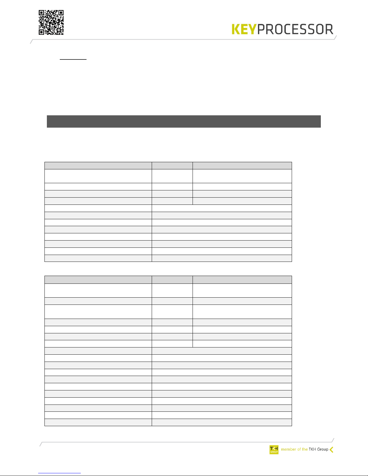
2.1 Functions and support
Depending on the use of the Orion, more or less functionality is available. The table below
shows the features:
Overview > Orion as Orbit replacement unit:
Amount
Connection
Orions (per port)
1
Controller type: iPU-8 (Max. 8
Orions) or Polyx (Max. 2 Orions)
Digital inputs
8
A1, A2, A3, A4, A5 A6, T1, T2
Digital outputs
4
H1, H2, O2, O5
Card reader Wiegand/ABA
2
LD, D0, D1, C en V+
LED status
Yes
Communication
PRT1 - RS422
Internal temperature measurement
Yes
Power supply measurement
Yes
Reader power measurement
Yes
Current: card readers
Yes
Overcharge / Short circuit H1 H2
Yes
Softstarting outputs
Yes
Overview > Orion in a communication bus:
Amount
Connection
Orions (per bus)
8
Controller type: Polyx (Max. 16
Orions per Polyx)
Digital inputs
2
T1, T2
Digital outputs
8
O1, O2, O3, O4, O5, O6, H1 en
H2
Monitort inputs (ADC)
6
A1, A2, A3, A4, A5, A6
Orion tamper input
1
T
Card reader Wiegand/ABA
2*
LD, D0, D1, C en V+
kpSensor
2**
C, S
Location buzzer
Ja
LED status
Ja
Audio
Future use
microSD card
Future use
Communication type
PRT 2 - RS485
Internal temperature measurement
Yes
Power supply measurement
Yes
Reader power measurement
Yes
Current: card readers
Yes
Overcharge / Short circuit H1 H2
Yes
Softstarting outputs
Yes

5
* D0 and D1 are combined inputs. When no card reader is connected, D0 and D1 can be used
as Digital input.
** Only the combined Temperature and Humidity sensor (T/H sensor) is supported.
6
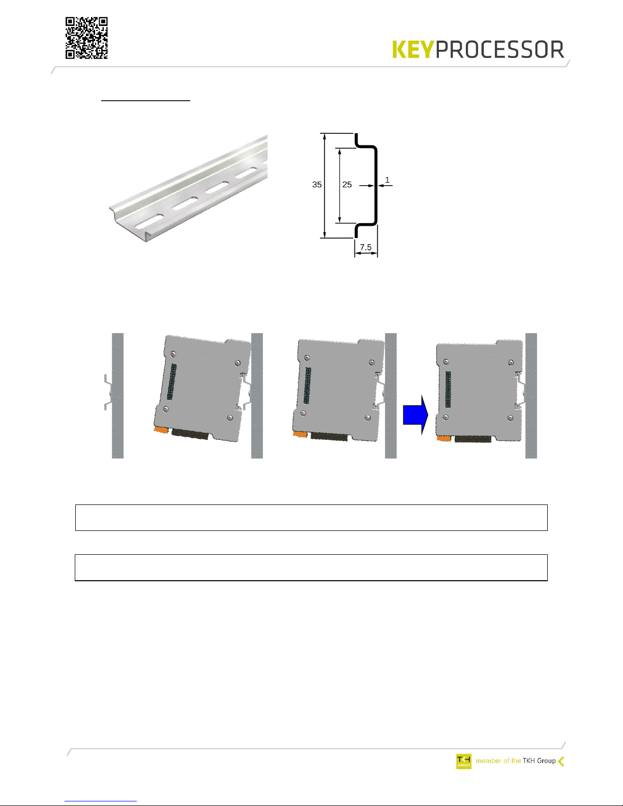
3 Mounting
For installation, use a mounting rail profile: 35 mm, according to EN 50022
Figure1: 35mm mounting rail profile Figure2: dimensions in mm
Install the mounting rail profile on the wall or in a secure cabinet
Push the Orion against the rail and click it in
Mounting the Orion on the profile
Note! When the Orion is installed in an existing Keyprocessor cabinet (PN: 501-1865),
the mounting rail must be positioned in the middle of the cabinet.
Note! When installing the Orion, write down the serial number and location of the
device.
7
A
B/C
D L J/K
I
E F G H
H
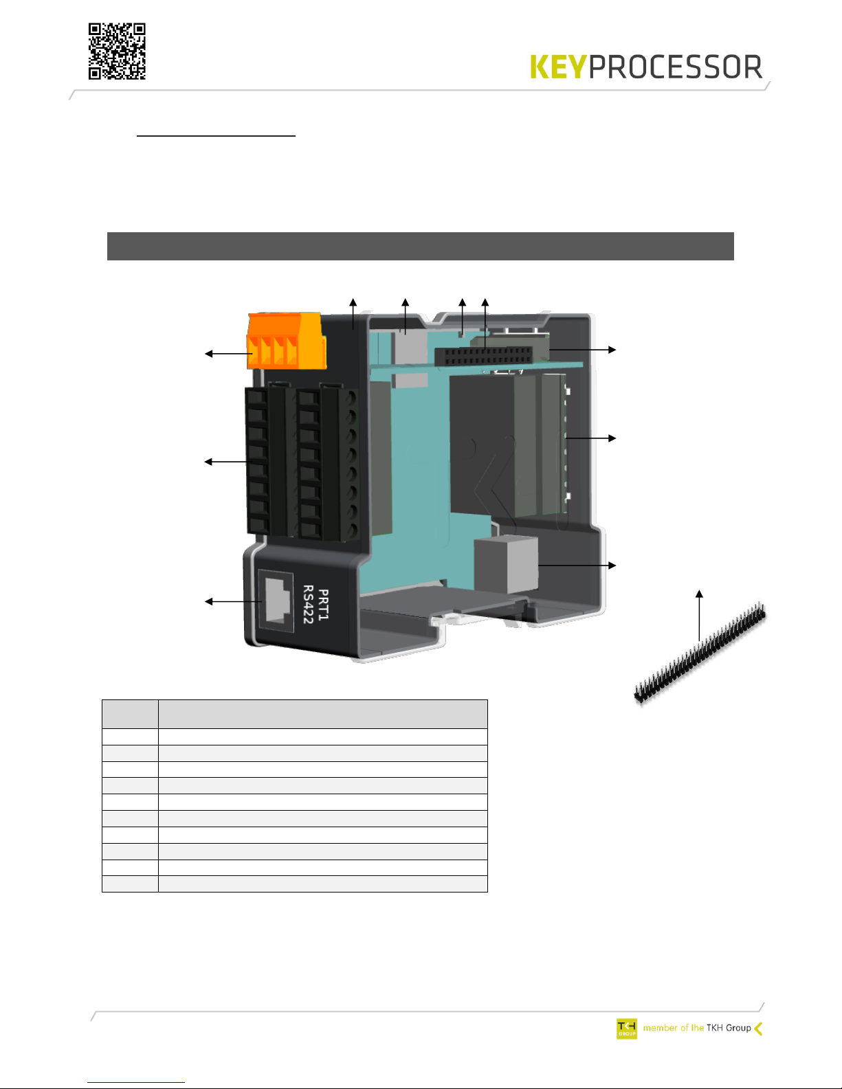
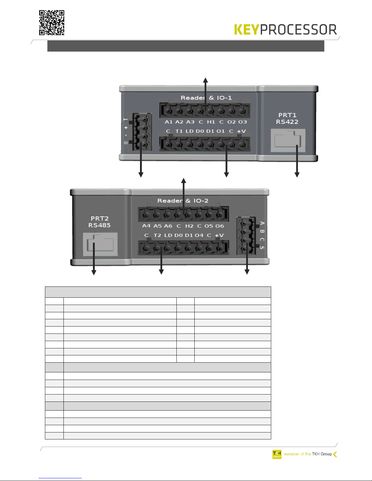
4 Connections
In this chapter, the connections of the Orion are described. The possibilities depents on the use
of the Orion (e.g. Orion as replacement unit for the reader Orbit or multiple Orion’s on one
data line).
4.1 Orion
* Function not supported, future use.
Port
Description
A
PRT1 - RS422 (Orbit mode)
B/C
Reader & IO-1
D
Power connector
E
Smart LED status
F
microSD slot*
G
End of line jumper
H
Stack connector for stacking the power supply
I
RS485 and kpSensor bus
J/K
Reader & IO-2
L
PRT2 - RS485 (Orion mode)
8
L
4.1.1 Labels
In this chapter, the labels of the Orion will be described, whereby ADC stands for Analog /
Digital Converter:
Reader & IO-1
B
Description
C
Description
C
GND (digital ground)
A1
ADC input 1
T1
Digital input (card reader tamper)
A2
ADC input 2
LD
LED control card reader
A3
ADC input 3
D0
DO/Data or Digital input
C
GND (digital ground)
D1
D1/Clock or Digital input
H1
High Power output 1
O1
Digital output 1
C
GND (digital ground)
C
GND (digital ground)
O2
Digital output 2
+V
Power connection card reader
O3
Digital output 3
D
Description
⏚
Earth ground
-
GND (digital ground)
+
Power connection Orion (12-24V DC)
T
Tamper input Orion
I
Description
A
A-RS485
B
B-RS485
C
GND (digital ground), only for use of communication or the sensor!
S
kpSensor
K
L J I
D B A
C
9
Reader & IO-2
J
Description
K
Description
C
GND (digital ground)
A4
ADC input 4
T2
Digital input (card reader tamper)
A5
ADC input 5
LD
LED control card reader
A6
ADC input 6
D0
DO/Data or Digital input
C
GND (digital ground)
D1
D1/Clock or Digital input
H2
High Power output 2
O4
Digital output 4
C
GND (digital ground)
C
GND (digital ground)
O5
Digital output 5
+V
Power connection card reader
O6
Digital output 6
Note! The Orion may not be connected to the network. If it does, it can cause serious damage
to the unit with loss of function.
4.1.2 Power supply- and tamper
The power supply connection of the Orion is provided with an orange connector. The power
connection is for each Orion the same. However, the tamper can only be used if the Orion is
used in a bus system.
Each Orion should be equipped with its own power source, with the exception of using the
stack connector. Depending on the power supply, 4 Orions can be stacked. When using more
than 300mA door locks, the C (ground) of the High Power output Orion must be wired
separately to the power supply (-).
The Orion accepts a supply voltage of 12.0 - 24.0
VDC. A higher input voltage results in a lower power
consumption and provide cost-effective wiring with a
smaller diameter of the conductor. When using an
external power supply, it must comply with the SELV
guidelines.
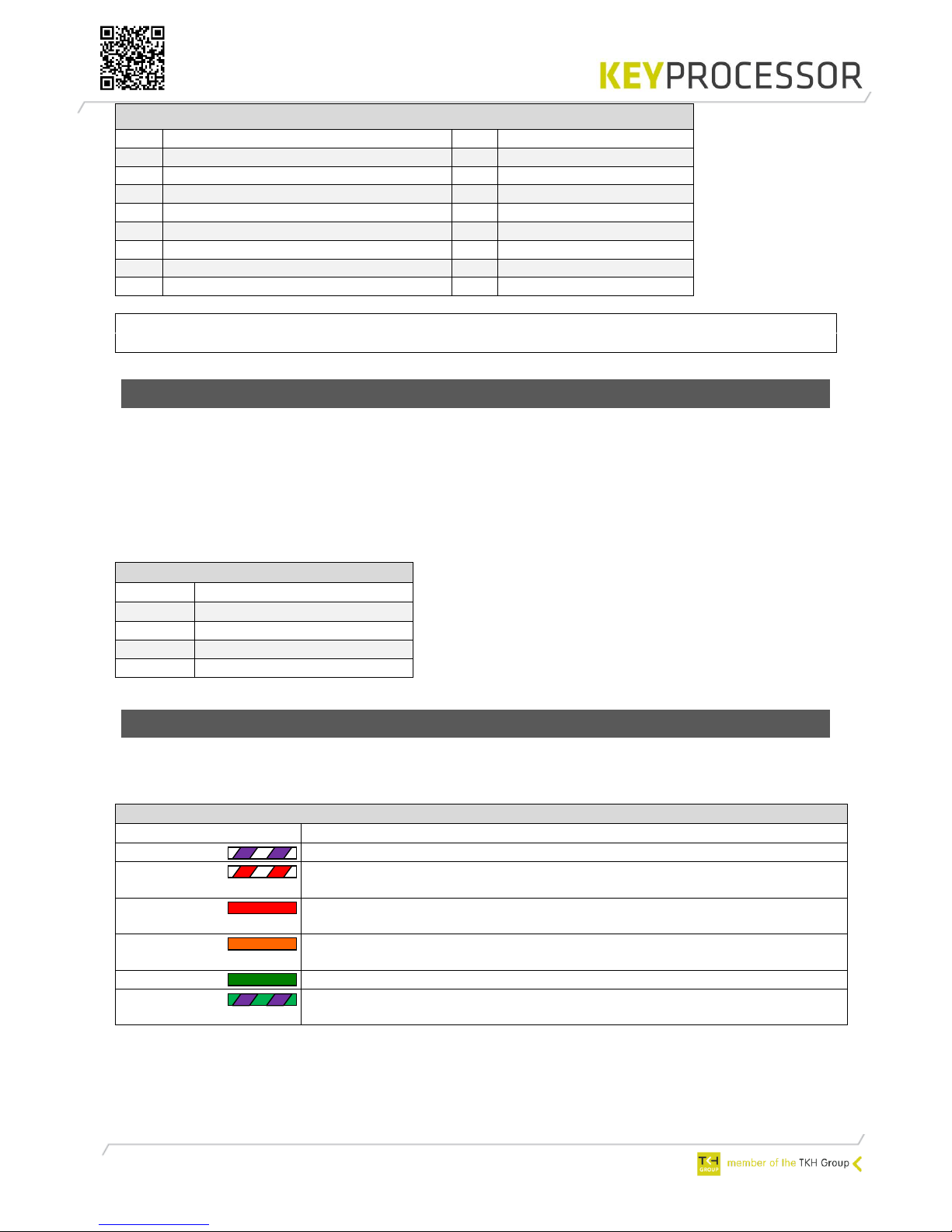
4.1.3 Smart LED status
The meaning of this RGB LED is to be able to read out the current status of the Orion.
Overview LED status:
Connector D
Label
Omschrijving
⏚
Earth ground
C
GND (digital ground)
+
12V – 24VDC
T
Tamper input Orion
Port D
LED color
Description
Violet
Programming mode. During programming the LED will blink fast
Red
When the LED is blinking (fade in/fade out): the Orion does not
communicate
Red
When the LED is continuously active, the Orion does not
communicate and an overload or short circuit is detected
Orange
When the LED is continuously active: the Orion is communicating but
an overload or short circuit is detected
Green
Orion is working- and communication properly
Green/Violet
When the location buzzer is activated, the green status LED will blink
green and violet.

10
PRT1
RS422
PRT1
RS422
max. 8
5 Orion as replacement unit for reader Orbit
When programming the Orion (within iProtect™) as a node type "Orbit (RS422)", the Orion
will be used as a substitute for the reader Orbit (1 and 2). There is no need to update the
iProtect™ software.
The UTP cabling, the connection between Network controller and Orion, needs to be
connected to PRT1 of the Orion.
The Orion supports Clock/Data- and Wiegand card readers, which is similar as the Orbit.
5.1 Connecting to an iPU-8 Network controller
The functionality of the Orion is compatible with the Orbit 2. All I/O of the Orbit 2 is available
on de Orion. However, the specifications of the I/O are different and needs to be taken into
account.
Below is a installation example displayed. A combination of existing Orbits and new Orion’s is
also possible:

11
PRT1
RS422
max. 2
Afbeelding
T-568B
5.2 Connecting to an Polyx Network controller
The functionality of the Orion is compatible with the Orbit 2. All I/O of the Orbit 2 is available
on de Orion. However, the specifications of the I/O are different and needs to be taken into
account.
Below is a installation example displayed. A combination of existing Orbits and new Orion’s is
also possible:
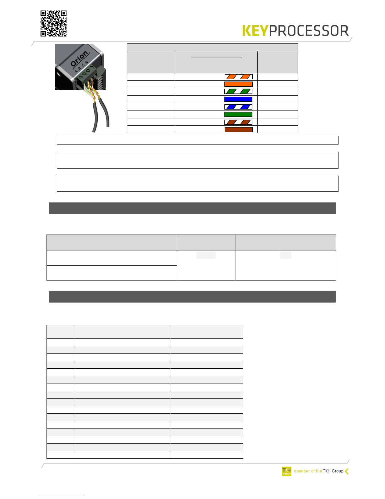
5.3 Controller <> Orion PRT1 - RS422
Connection: Controller <> Orion
iPU-8 PRT 1 – 8
or
Polyx PRT 2 – 3
TIA/EIA-568-B
kabelkleur
Orion (A)
PRT1
RS422
1
White/Orange
RX1B
2
Orange
RX1A
3
White/green
TX1B
4
Blue
12V dc
5
White/blue
GND
6
Green
TX1A
7
White/brown
GND
8
Brown
GND

12
5.3.1 Cabling requirement
The required cable between the Orion and the Network controller is displayed below:
Cable
Communication type
Distance
Communication between
UTP/STP Cat ≥3
RS422
1200m
Netwerk controller and Orion
5.3.2 Card reader and IO connections
When exchanging a reader Orbit for an Orion Smart door controller the following table may be
used:
Orbit 2
Reader 1
Connection
description
Orion
Reader & IO-1
iProtect™ default
+5V 200mA MAX
Reader power
+V
GND
GND (digital ground)
C
D1 / CLK
D1 / Clock
D1
D0 / DAT
D0 / Data
D0
LED
LED
LD
⏚
Earth ground
⏚
Inputs 1
Inputs 1
Input/Output
IN0
Digital input
A1
Loop
COM 0+1
GND (digital ground)
C
C
IN1
Digital input
A2
Push button
IN2
Digital input
A3
Door status
COM 2+3
GND (digital ground)
C
IN3
Digital input
T1
Door in latch mode
Outputs 1
Outputs 1
0
Digital output
H1
Door control
GND
GND (digital ground)
C
1
Digital output
O2
Alarm
Orbit 2
Reader 2
Connection
description
Orion
Reader & IO-2
iProtect™ default
+5V 200mA MAX
Reader power
+V
GND
GND (digital ground)
C
D1 / CLK
D1 / Clock
D1
D0 / DAT
D0 / Data
D0
LED
LED
LD
⏚
Earth ground
⏚
Inputs 2
Inputs 2
Input/Output
IN0
Digital input
A4
Loop
COM 0+1
GND (digital ground)
C
C
IN1
Digital input
A5
Push button
IN2
Digital input
A6
Door status
COM 2+3
GND (digital ground)
C
IN3
Digital input
T2
Door in latch mode
Outputs 2
Outputs 2
0
Door Output
H2
Door control
GND
GND (digital ground)
C
1
Alarm output
O5
Alarm

13
5.4 Diagnosing
The Orion can be fully tested before it communicates with iProtect™. To start this test, a
diagnostic program which is running on the Network controller must started.
Testing the Orion as replacement unit for the Orbit is explained in chapter 7.2 and 7.3.1

14
6 Multiple Orion’s on one data line (bus)
When programming the Orion (within iProtect™) as a node type "Orion", multiple Orion’s can
communicate using the same data line (bus). The iProtect™ software needs to be updated to
≥8.03 to program this type.
The maximum amount of Orion’s on one data line is 8. The last Orion should be provided with
an End Of Line (EOL) jumper. The communication line is NOT provided of power, every Orion
should be equipped with its own power supply.
The UTP cabling, the connection between Network controller and Orion, needs to be connected
to PRT2 of the Orion.
The Orion supports Clock/Data- and Wiegand card readers, which is similar as the Orbit.
Note! When installing the Orion, write down the serial numbers and locations of the devices
Note! The Polyx is always at the beginning of the communication line!
6.1 Connecting to an Polyx Network controller
max. 8
PRT2
RS485
max. 8
PRT2
RS485

15
Example: 1
Picture
T-568B
Picture RS485
connection
6.1.1 Direct connection
The first Orion on the communication line can directly be connected on port PRT2. This makes
it possible to use standard UTP cable with RJ45 connectors between the Network controller and
the Orion. From this Orion the screw connector (I) can be used to build up the communication
line to the next Orion, see example 1.
It is also possible to make use of the screw connection directly, see example 2.
Connection: Polxy <> Orion
Polyx
PRT 2 - 3
TIA/EIA-568-B
Cable color
Orion (L)
PRT2
RS485
1
White/Orange
B
2
Orange A 3
White/green
B
4
Blue
12V dc
5
White/blue
GND
6
Green
A
7
White/brown
GND
8
Brown
GND
Connection: Orion <> Orion
Orion (I)
A B C S
RS485
TIA/EIA-568-B
Cable color
Orion (I)
A B C S
RS485
B
White/Orange
B
A
Orange A B
White/green
B
-
Blue
-
-
White/blue
-
A
Green
A
C
White/brown
C
C
Brown
C
UTP CAT 5/6
RS485 bus
PRT2
RS485
max. 8 per bus
I
I
L
L

16
Remark: When using a shielded wire (conductive), the shield should be attached
on one side to earth (⏚) of the installation housing.
Note! The last Orion on the communication line must be provided of an EOL
jumper.
6.1.2 Using an adapterboard
When it is not possible to use a standard UTP cable between the Orion and the Network
controller, an adapter board can be used.
A direct connection (without using an adapterboard) between the Orion and a Polyx™ is NOT
possible when:
Orion and Polyx™ are installed in different buildings and thus the connection
leaves the building or
the wiring is no UTP cable (CAT5 or CAT6) or
an existing (non UTP) cable is reused or
overvoltage protection is required
Standard UTP CAT5 is used between an adapterboard and Polyx™
RS485 bus
UTP CAT 5
I
I
max. 8 per bus
Example: 2
I
I
RS485 bus
max. 8 per bus
L
L
17
Picture RS485
connection
Note! The Polyx must always be at the beginning of the communication line.
Remark: When using a shielded wire (conductive), the shield should be attached
on one side to earth (⏚) of the installation housing.
Note! The last Orion on the communication line must be provided of an EOL
jumper.
6.1.3 Cabling requirement
The required cable between the Polyx™ Network controller and the Orion(s) is displayed
below:
6.1.4 Card reader and IO connections
In the table below the labels-, connections- and the defaults are defined.
Reader & IO 1:
Connection: Orion <> Orion
Orion (I)
A B C S
RS485
TIA/EIA-568-B
Cable color
Orion (I)
A B C S
RS485
B
White/Orange
B
A
Orange A B
White/green
B
-
Blue
-
-
White/blue
-
A
Green
A
C
White/brown
C
C
Brown
C
Cable
Communication
type
Total bus length (meter)
CAT5/6 UTP four twisted pairs of 24AWG
copper conductors
RS485
600
Minimal 24AWG twisted pairs of 24AWG
copper conductors, shielded
Label
Description
iProtect default
C
GND (digital ground)
T1
Digital input (Reader tamper)
Door in latch mode
LD
LED control
D0
D0 / Data or Digital input*
D1
D1 / Clock or Digital input*
O1
Digital output
C GND (digital ground)
+V
Reader power
A1
ADC input 1 **
Loop
A2
ADC input 2 **
Push button
A3
ADC input 3 **
Door status
C
GND (digital ground)
H1
High Power output
Door control
C
GND
O2
Digital output
Alarm
O3
Digital output

18
UTP
Reader & IO-2:
* When no card reader is connected, D0 and D1 can be used as Digital input
** It is possible to use analog inputs (monitored inputs). This makes it possible to connect
inter alia detectors, smoke detectors or monitored door contacts on the Orion.
6.1.5 kpSensor connection
The Orion has one kpSensor connection. When connection a sensor on the Orion it is possible
to measure the environment (temperature and/or humidity).
Port I
Label
Description
Cable length
Supported kpSensors
Cable type
C
GND
30m 2 UTP
S
kpSensor
Picture T-568B
Remark The Orions only supports the combined Temperature and Humidity sensor (T/H
sensor).
Label
Description
iProtect default
C
GND (digital ground)
T2
Digital input (Reader tamper)
Door in latch mode
LD
LED control
D0
D0 / Data or Digital input*
D1
D1 / Clock or Digital input*
O4
Digital output
C GND (digital ground)
+V
Reader power
A4
ADC input 4 **
Loop
A5
ADC input 5 **
Push button
A6
ADC input 6 **
Door status
C
GND (digital ground)
H2
High Power output
Door control
C
GND (digital ground)
O5
Digital output
Alarm
O6
Digital output
Connection: Orion <> kpSensor
Port I
TIA/EIA-568-B
Cable color
Sensor
-
Wit/oranje 1 -
Oranje 2 -
Wit/groen 3 S
Blauw
4
C
Wit/blauw
5
-
Groen
6
-
Wit/bruin
7
-
Bruin
8

19
6.1.6 Diagnosing
The Orion can be fully tested before it communicates with iProtect™. To start this test, a
diagnostic program which is running on the Network controller must started.
In chapter 7.3.2 will be explained how to test the Orion(s).

20
7 Diagnostic menu
7.1 Connecting to the Network controller console
port
For a diagnosis with a pc or laptop there is an installation diagnosis menu, ‘Diagnostics'. It is
not necessary to download all settings via a user interface. After connecting the hardware,
without an exchange being present, it can be checked, locally via a simple terminal program,
whether all hardware is operational.
There are many different programs, like Teraterm, which can emulate a VT100 terminal on a
PC. Using a simple laptop, diagnostics can be logged in via the serial port in the Polyx.
Connect your PC for example to port “Console” from the Network controller. Use the
adapter shown below (available at Keyprocessor BV).
Open a terminal program and make a connection. (e.g. Tera term)
Select the COM-port of the PC connected to the Network controller.
iPU-8: Choose a baud rate of “9600”, Data ‘8 bit”, Stop ‘1 bit’, Parity ‘None’ and flow
control “none”.
Polyx: Choose a baud rate of “115200”, Data ‘8 bit”, Stop ‘1 bit’, Parity ‘None’ and
flow control “none”.

21
7.2 Start diagnostics using an iPU-8
When after starting-up the iPU-8, the line ‘Hit any key within 5s to run diagnostics...’
appears and a key is pressed within five seconds, then the diagnostics program is
started.
The main menu has the following appearance:
--- iPU-8 diagnostics V1.00 ---
1) Environment settings
2) Test serial ports (loopback)
3 Test profi-device communications
4) Test profi-device functionality
5) Show board revision and test diag leds & inputs
6) Test Power
7) Test EEPROM
8) Test RTC
9) Test Watchdog
q) Start application
r) Restart system
Enter menu option:
Screen 1: Main menu iPU-8 Diagnostics
Only options 2 and 3 are needed for the installer to test the Orion.
Option 3: Profibus communication test
If in the main menu of the IPU-8 Diagnostics program option 3, Test profi device
communications, is chosen, the user is taken to the Profibus DP communication test screen
(screen 2).This allows the user to set per port whether a Profibus appliance is connected and if
so, which slave that is. Whether there is communication (connected/disconnected) can be
found under Communication Status. The identification number of the appliance in question, as
well as the hardware and software version numbers, are also displayed on this screen.
--- Profibus DP communication test ---
Comm. status Ident no. Hw/Sw version
------------ --------- ---------------
1) Profi slave 1 Connected 0xfffd IE-ORBRD2 V1.03
2) Profi slave 1 Connected 0xfffd KP-ORION V1.00
3) Profi slave 1 Connected 0xfffd IE-ORBRD2 V1.03
4) No profi-dev. Disconnected
5) No profi-dev. Disconnected
6) No profi-dev. Disconnected
7) No profi-dev. Disconnected
8) No profi-dev. Disconnected
1..8) : toggle device type S) : toggle start/stop Q) : Quit
Screen 2: Profibus communication test
If in the main menu of the IPU-8 Diagnostics programme option 4, Test profi-device
functionality, is chosen, the user can test whether the connected equipment itself is
functioning properly. The user is first asked to enter the port to which the appliance to be
tested is connected. Next, the various types of equipment which can be connected are
displayed.
In the next example option 2, Profi DP reader-2, has been selected:

22
--- Device functionality test ---
Enter the device to test 1..8) : 1
1) Profi DP lezer-1
2) Profi DP lezer-2
3) Profi DP io
Enter the device type : Profi DP lezer-2
Enter slave no. 1)..4) (CR=1) : 1
MT interface or Wiegand interface [M/W] for lezer 1 ? : M
MT interface or Wiegand interface [M/W] for lezer 2 ? : M
Continue [Y] ? :
Screen 3: Device functionality test
In this screen the user is first asked to enter the slave number. This value is always 1. Then
the user is asked to enter the interface type (MT or Wiegand). Finally, if it is confirmed that all
input is correct, and the user wants to continue, the next screen will display the options and
status of the selected appliance:
--- Profibus DP orbit lezer test, no. 2 ---
Label Orion
1) Output R1-0: On : (H1)
2) Output R1-1: On : (O2)
3) Output R2-0: On : (H2)
4) Output R2-1: On : (O5)
5) RdrLED R1
6) RdrLED R2
Input R1-0: Off 128 : (A1)
Input R1-1: Off 128 : (A2)
Input R1-2: Off 128 : (A3)
Input R1-3: Off 128 : (T1)
Input R2-0: Off 128 : (A4)
Input R2-1: Off 128 : (A5)
Input R2-2: Off 128 : (A6)
Input R2-3: Off 128 : (T2)
Reader : R1: 29748424 08
State : Data exch.
1)... : toggle output state or flash lezerled S) : stop
Screen 4: Device functionality test, options and status of an Orion but working as an reader Orbit
In the screen above the in- and outputs can be tested. Using keys 1 through 4 the
outputs can be turned on and off. It is possible to test the reader LEDs via key 5 or
6 (five times turned on or off quickly).
When a card is presented to one of the readers, the card data will be displayed in
the field Reader. R1 indicates that Reader 1 has been reading a card; R2 indicates
that Reader 2 has read the card. The number against the card number that has
been read (here 08) records the number of digits the card number is composed of.

23
7.3 Start diagnostics using an Polyx
Depending on function and connection method (PRT1 or PRT2 of the Orion), you can use
certain parts of the diagnostics menu. Both ways are described in the following chapters.
7.3.1 Orion as replacement unit for reader Orbit
When after starting-up the Polyx, the line ‘Hit any key within 5s to run diagnostics...’
appears and a key is pressed within five seconds, the diagnostics program is started.
The main menu has the following appearance:
Polyx Diags version V3.0.5
1) Environment settings
2) Test onboard I/O
3) Test RS422 devices (loopback)
4) Test profi-device Communications
5) Test profi-device functionality
6) Test Orion-device Communications
7) Test Orion-device functionality
8) Clean nodemgr
9) Test Watchdog
a) Clean system
b) Clean /etc/rc.d/* to /etc/save.d/*
v) Version
p) Polyx menu
q) Start application
r) Restart system
Enter menu option:
Screen 1: Main menu Polyx Diagnostics
Only options 4 and 5 are needed for the installer to test the Orion.
Optie 4: Profibus communication test
If in the main menu of the Polyx Diagnostics program option 4, Test profi device
communications, is chosen, the user is taken to the Profibus DP communication test screen
(screen 2).This allows the user to set per port whether a Profibus appliance is connected and if
so, which slave that is. Whether there is communication (connected/disconnected) can be
found under Communication Status. The identification number of the appliance in question, as
well as the hardware and software version numbers, are also displayed on this screen.
--- Profibus DP communication test ---
Comm. status Ident no. Hw/Sw version
------------ --------- ---------------
1) Profi slave 1 Connected 0xfffd IE-ORBRD2 V1.03
2) Profi slave 1 Connected 0xfffd KP-ORION V1.00
1..8) : toggle device type S) : toggle start/stop Q) : Quit
Screen 2: Profibus communication test
If in the main menu of the Polyx Diagnostics program option 5, Test profi-device functionality,
is chosen, the user can test whether the connected equipment itself is functioning properly.
The user is first asked to enter the port to which the appliance to be tested is connected. Next,
the various types of equipment which can be connected are displayed.
In the next example option 2, Profi DP reader-2, has been selected:

24
--- Device functionality test ---
Enter the device to test 1..8) : 1
1) Profi DP lezer-1
2) Profi DP lezer-2
3) Profi DP io
Enter the device type : Profi DP lezer-2
Enter slave no. 1)..4) (CR=1) : 1
MT interface or Wiegand interface [M/W] for lezer 1 ? : M
MT interface or Wiegand interface [M/W] for lezer 2 ? : M
Continue [Y] ? :
Screen 3: Device functionality test
In this screen the user is first asked to enter the slave number. This value is always 1. Then
the user is asked to enter the interface type (MT or Wiegand). Finally, if it is confirmed that all
input is correct, and the user wants to continue, the next screen will display the options and
status of the selected appliance:
--- Profibus DP orbit lezer test, no. 1 ---
1) Output R1-0: On : (H1)
2) Output R1-1: On : (O2)
3) Output R2-0: On : (H2)
4) Output R2-1: On : (O5)
5) RdrLED R1
6) RdrLED R2
Input R1-0: Off 128 : (A1)
Input R1-1: Off 128 : (A2)
Input R1-2: Off 128 : (A3)
Input R1-3: Off 128 : (T1)
Input R2-0: Off 128 : (A4)
Input R2-1: Off 128 : (A5)
Input R2-2: Off 128 : (A6)
Input R2-3: Off 128 : (T2)
Reader : R1: 29748424 08
State : Data exch.
1)... : toggle output state or flash lezerled S) : stop
Screen 4: Device functionality test, mogelijkheden en status van een Orion als lezer Orbit
In the screen above the in- and outputs can be tested. Using keys 1 through 4 the
outputs can be turned On and Off. It is possible to test the reader LEDs via key 5 or
6 (five times turned on or off quickly).
When a card is presented to one of the readers, the card data will be displayed in
the field Reader. R1 indicates that Reader 1 has been reading a card; R2 indicates
that Reader 2 has read the card. The number against the card number that has
been read (here 08) records the number of digits the card number is composed of.

25
7.3.2 Multiple Orion’s on one date line (bus)
When after starting-up the Polyx, the line ‘Hit any key within 5s to run diagnostics...’
appears and a key is pressed within five seconds, the diagnostics program is started.
The main menu has the following appearance:
Polyx Diags version V3.0.5
1) Environment settings
2) Test onboard I/O
3) Test RS422 devices (loopback)
4) Test profi-device Communications
5) Test profi-device functionality
6) Test Orion device
7) Clean nodemgr
8) Test Watchdog
9) Clean system
c) Clean /etc/rc.d/* to /etc/save.d/*
v) Version
p) Polyx menu
q) Start application
r) Restart system
Enter menu option:
Screen 1: Main menu Polyx Diagnostics
Only options 6 is needed for the installer to test the Orion. (Polyx Diags version ≥V3.05 is
needed).
Optie 6: Orion device functionality
When option 6 is selected “Test Orion device”, select the communication port of the Polyx
PRT2 (1) - PRT3 (2) (on which port the Orion(s) are connected).
--- Device functionality test ---
Enter the interface to test 1..2) :
Scanning done, please select an Orion device:
1) Orion snr: 140025, V1.0.20
2) Orion snr: 140026, V1.0.20
3) Orion snr: 140028, V1.0.20
4) Orion snr: 140040, V1.0.20
5) Orion snr: 140042, V1.0.20
6) Orion snr: 140043, V1.0.20
7) Orion snr: 140045, V1.0.20
8) Orion snr: 140046, V1.0.20
Enter the device to id to test 1..8) : 1
Screen 2: Device functionality test
In the screen above PRT2 (1) has been chosen. The connected Orions will be detected
automatically. The serial numbers of the Orions will be displayed.
By making a choice 1-8 (in our example 1, with serial number 140025) the following screen
appears and the specific Orion can be tested.

26
--- Orion test >> snr: 140025, V1.0.20 --Reader & IO-1
---------------------------- ---------------------
Input A1: off 128 (15939ohm) 1) Output O1: On/Off
Input A2: off 128 (15939ohm) 2) Output 02: On/Off
Input A3: off 128 (15939ohm) 3) Output O3: On/Off ----- general ----
Input T1: Off 128 4) Output H1: On/Off B)Buzzer : Off
Input D0: off 128 5) RdrLED R1 toggle
Input D1: Off 128 Input T :off 128
Input(v) :26.58V
Reader & IO-2 Reader(v):12.00V
--------------------------- ---------------------- Reader(a): 0.05A
Input A4: off 128 (15939ohm) 6) Output O4: On/Off Temp(K) : 240.0K
Input A5: off 128 (15939ohm) 7) Output 05: On/Off
Input A6: off 128 (15939ohm) 8) Output O6: On/Off
Input T2: Off 128 9) Output H2: On/Off
Input D0: Off 128 A) RdrLED R2 toggle
Input D1: Off 128
Reader [1 or 2] (ABA) > 29748424
1-B).. : toggle output state F) change format S) : stop
Scherm 3: Device functionality test, mogelijkheden en status van een Orion
In the screen above the in- and outputs can be tested. Using keys 1 - 4 and 6 - 9
outputs can be turned On and Off. It is possible to test the reader LEDs via key 5 or
a (five times turned on or off quickly).
When a card is presented to one of the readers, the card data will be displayed in
the field Reader. R1 indicates that Reader 1 has been reading a card; R2 indicates
that Reader 2 has read the card. The number against the card number that has
been read.
When using option F, the format of the analog input data can be changed (Ohm / raw data).

27
8 Technical specifications
Housing
Measurements:
110,0 x 47,0 x 93,0 mm (L x W x H)
Weight:
0,25 Kg
Mounting
Dinrail
35 mm (NEN-EN 50022)
Communication
PRT1
RJ45 socket, RS422
Pin out
Pin 1 = RXB Pin 5 = GND
Pin 2 = RXA Pin 6 = TXB
Pin 3 = TXB Pin 7,8 = GND
Pin 4 = 12V dc
PRT2
RJ45 socket, RS485
Pin out
Pin 1 = RXB Pin 5 = GND
Pin 2 = RXA Pin 6 = RXA
Pin 3 = RXB Pin 7,8 = GND
Pin 4 = 12V dc
Card reader
Reader power (+V)
Voltage
12.0V DC
Current
500mA (one Polyfuse for both readers)
Interface
Clock/Data
depending of used cable and card reader
Wiegand
depending of used cable and card reader
Power supply & consumption
Voltage (+)
12,0 – 24V DC
Power
Average
0,48W (no load)
Digital I/O
Digital output (O1, O2, O3, O4, O5, O6)
max. Voltage 28V; Open collector output; sinked
current. Max. current 300mA (Polyfuse)
High power output (H1, H2)
Current limiting, switching to GND, max. 2.5A
Digital input (T1, T2)
Switching to GND, <20K ohm
Digital input (D0/D1) Reader IO-1
Switching to GND, <20K ohm
Digital input (D0/D1) Reader IO-2
Switching to GND, <20K ohm
Environment inputs
ADC input (A1, A2, A3, A4, A5, A6)
value
0-60K ohm. Response time <250ms
Switching to GND, <2K ohm. Response
time 20ms
Environment sensor
kpSensor
Sensor
kpSensor
2
Type
Temperature/Humidity
Indicators
Visual
RGB-LED
Sound
Multi-tone buzzer
microSD
microSD
Type: SDHC, up to 32GB
End of line jumper
End Of Line resistor
120 ohm

28
Environment
Usage
Indoor
Temperature
-35°C to +70°C
Humidity
20 ~ 90% RH non-condensing
Storage temperature and humidity:
-40 ~ +85°C, 10 ~ 95% RH
Polyfuse
Type
PTC Fuse Case style
Thermal derating
At -10° C the hold current will increase to 130%
At +25° C no derating
At +60° C the hold current will reduced to 60%
Certifications
CE compliant
European limits and methods of measurement of radio
disturbance characteristics of information technology
equipment
EN 55022:2010
Alarm systems – Part 4: Electromagnetic compatibility –
Product family standard: Immunity requirements for
components of fire, intruder, holp up, CCTV, access control
and social alarm systems
EN 50130-4:2011

29
9 Annex
9.1 Sirius card reader with I-O
 Loading...