

Page 1
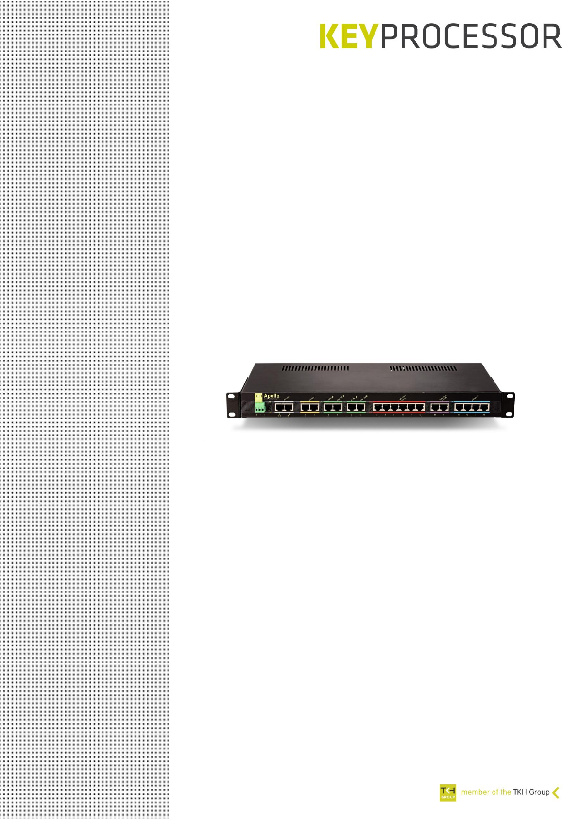
Apollo
Technical manual
o Internal jumper settings
o Connections and options
o Diagnostics
o Technical data
Page 2

Publication
June 2019,
Keyprocessor BV
Paasheuvelweg 20
1105BJ Amsterdam, The Netherlands
www.keyprocessor.com
Tel.: +31-20-4620700
This manual represents the knowledge at the above mentioned time. Keyprocessor works nonstop to improve her products. For the most recent technical information please contact your
consultant or dealer.
Content overview
Publication .................................................................................................................... 2
Content overview .......................................................................................................... 2
1 This document ................................................................................................ 4
1.1 Apollo Smart cabinet security controller ......................................................... 4
2 General .......................................................................................................... 5
2.1 Wiring ........................................................................................................ 5
2.2 Tools and equipment ................................................................................... 5
3 Installation start-up ......................................................................................... 6
4 Installing the Apollo into a rack ......................................................................... 7
4.1 Installing the mounting Brackets into the Apollo .............................................. 7
4.2 Attaching the Apollo to the rack .................................................................... 7
4.3 Powering the Apollo ..................................................................................... 8
5 Safety and detections ...................................................................................... 9
6 Internal connector and jumper settings ............................................................. 10
6.1 Power connection ....................................................................................... 10
6.2 Door lock overrule ...................................................................................... 10
6.3 Lock voltage .............................................................................................. 10
6.4 Internal supervised output 1 / FAN ............................................................... 11
6.5 Internal supervised output 2 ........................................................................ 11
6.6 Supervised output voltage ........................................................................... 11
6.7 Walk test ................................................................................................... 11
6.8 Power connection controller board ................................................................ 12
7 Smart cabinet security: System setup ............................................................... 13
7.1 Sockets and port overview........................................................................... 14
8 Apollo Smart cabinet security .......................................................................... 15
8.1 Power connector......................................................................................... 15
8.2 Led status ................................................................................................. 16
8.3 Controller: gray section ............................................................................... 16
8.3.1 Cable length .............................................................................................. 16
8.4 Sensors: yellow section ............................................................................... 17
8.4.1 Cable length .............................................................................................. 17
8.5 Reader and door I/O: green section .............................................................. 18
8.5.1 Cable length .............................................................................................. 19
8.5.2 Led status ................................................................................................. 19
8.6 Supervised inputs: red section ..................................................................... 20
8.6.1 Cable length .............................................................................................. 21
8.6.2 Led status ................................................................................................. 21
Page 3

8.7 Supervised outputs: violet section ................................................................ 22
8.7.1 Cable length .............................................................................................. 22
8.7.2 Led status ................................................................................................. 22
8.8 Digital I/O: blue section .............................................................................. 23
8.8.1 Cable lenght .............................................................................................. 23
8.8.2 Led status ................................................................................................. 24
9 Apollo diagnostic menu ................................................................................... 25
9.1 Connecting to the Apollo console port ........................................................... 25
9.2 Start diagnostic .......................................................................................... 25
9.3 Environment settings .................................................................................. 26
9.4 Digital IO test ............................................................................................ 27
9.5 Version ..................................................................................................... 28
9.6 Polyx menu ............................................................................................... 28
10 Technical specifications ................................................................................... 29
10.1 Output load de-rating curve ......................................................................... 31
11 Technical drawings ......................................................................................... 32
Page 4
1 This document
This document contains all the information which is needed when installing the Apollo. The
details and recommendations will be described in the chapters below.
1.1 Apollo Smart cabinet security controller
Apollo in combination with iProtect (Security Management System) offers you a complete
solution for monitoring the equipment of your critical locations/infrastructure. Think of Energy,
Water, Data-centers, Telecom and other technical unmanned locations.
Because the locations are unmanned, access control, alarm monitoring and environment
conditions becomes very important.
The Apollo can inter alia monitor the temperature, humidity and air flow but is also capable of
smoke-, intrusion- and water detection in the cabinet. This monitoring is essential to increase
the lifetime and reliability of the system and helps preventing malfunctioning, damage and
reduces operational costs.
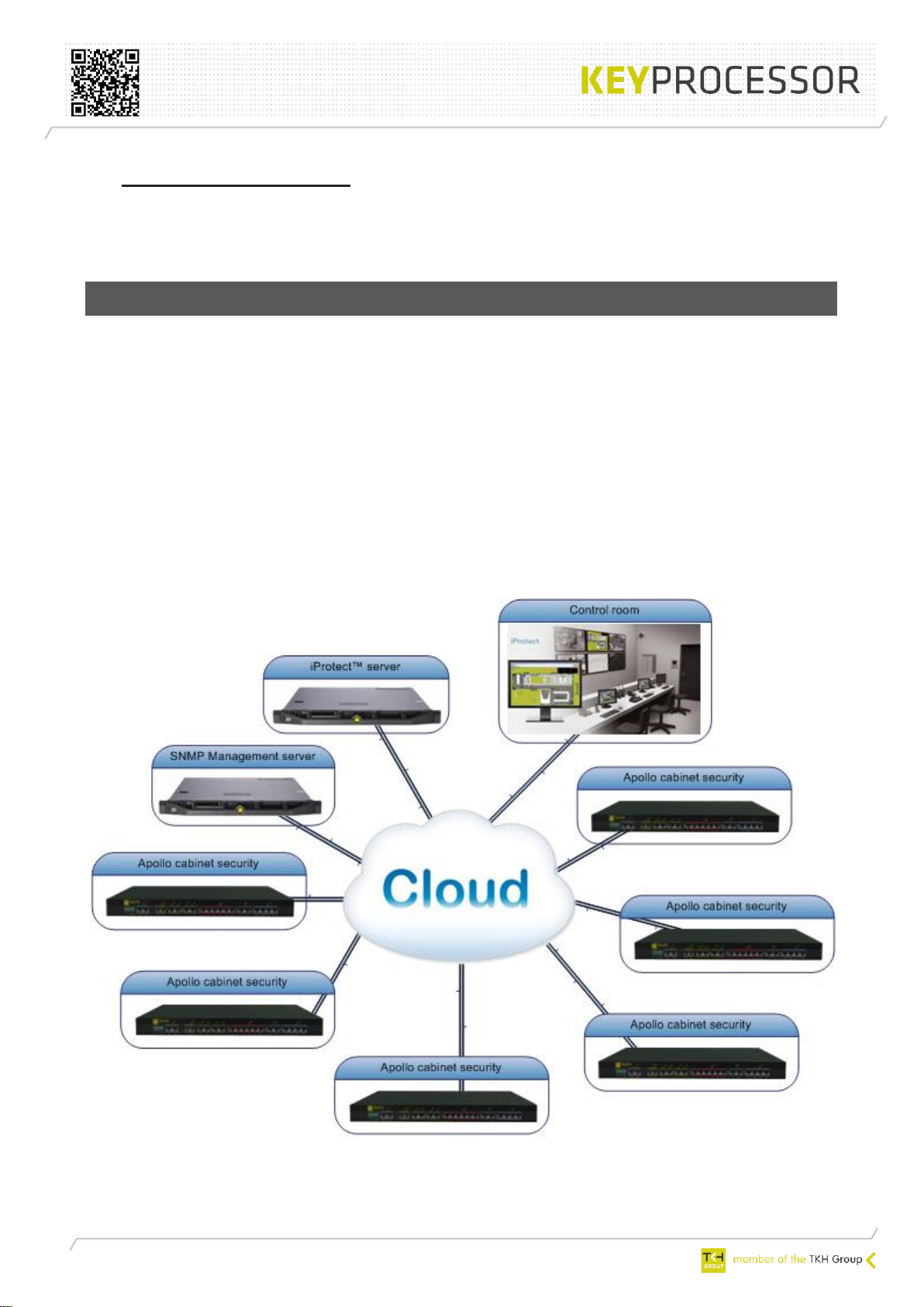
The operator can fully control the cabinet remotely using iProtect™.
iProtect is extremely suitable for monitoring a large amount of buildings, areas and cabinets.
However, in case iProtect will not be leading for monitoring the cabinet, the Apollo supports
SNMP (Simple Network Management Protocol).
iProtect™ and Apollo system overview
Page 5
2 General
The Apollo designed for a quick and easy installation. Nevertheless, we strongly recommend
that the technicians who installing the Apollo are trained and familiar with the product.
2.1 Wiring
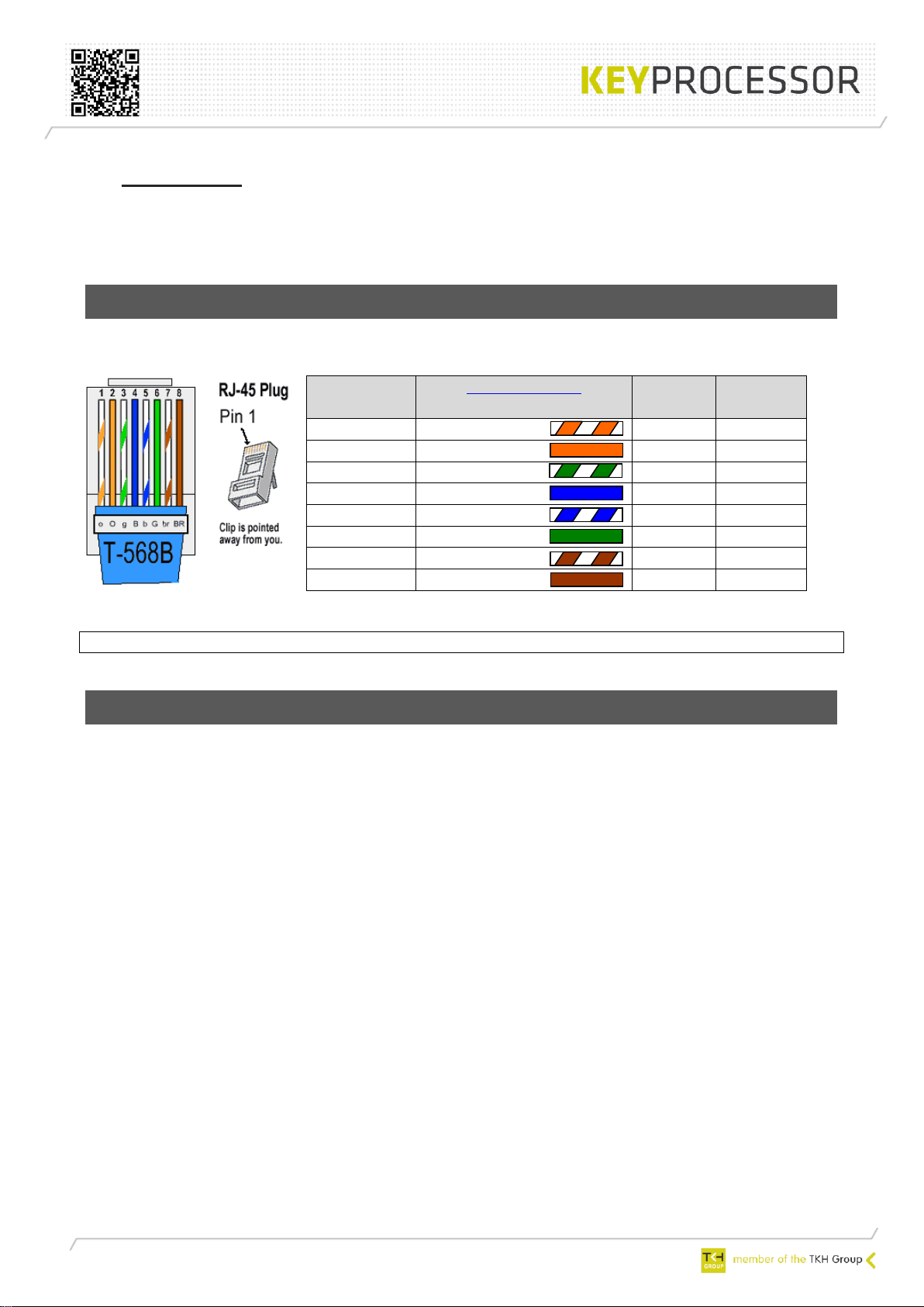
This document assumes standard T-568 color coding of the cables
Pin number
RJ-45 Plug
TIA/EIA-568-B
Cable color
Signal
ID
T568B
Pair
1
White/orange
DA+
2
2
Orange
DA-
2
3
White/green
DB+
3
4
Blue
DC+
1
5
White/blue
DC-
1
6
Green
DB+
3
7
White/brown
DD+
4
8
Brown
DD-
4
Picture T-568B
Note: The Apollo can be ordered with standard, ready to use cables!
2.2 Tools and equipment
When installing the Apollo, we recommend the installer the following tools and materials:
- T-568B cable
o Advised color: Blue, Yellow, Violet, Red and green
- RJ45 plugs
- Rod Rj45
- Wire side cutter
- Crosshead Philips Screwdriver
- Screwdriver
Page 6
3 Installation start-up
To ensure proper functioning of the Apollo, the environment of the Apollo must be compliant
with certain conditions..
Caution – Install the Apollo in a protected area that is free of excessive dust and
has adequate air flow. Do not operate the Apollo where the temperature and
humidity is outside the specified limits
Warning – The Apollo operates between a temperature of -10°C and +60°C and a
humidity of 20 ~ 90% RH non-condensing
Page 7
4 Installing the Apollo into a rack
The Apollo can be provided of two mounting brackets that can be used for a standard 19 inch
or metric rack installation.
Caution – Ensure that the temperature in the rack does not exceed the Apollo’s
maximum ambient rated temperatures. Consider the total airflow requirements
of all equipment installed in the rack, to ensure that the equipment is operated
within its specified temperature range.
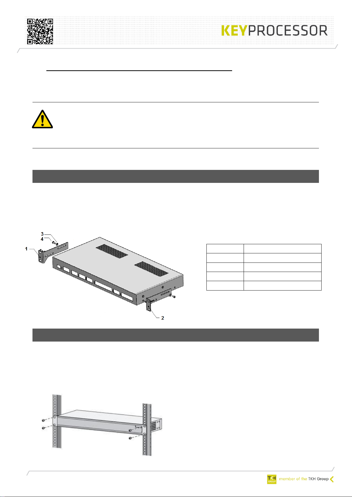
4.1 Installing the mounting Brackets into the Apollo
Use this procedure to install the mounting brackets onto the sides Apollo.
1. Unpack the carton box
2. Mount the supplied brackets to the Apollo housing (see picture below).
4.2 Attaching the Apollo to the rack
1. Position the Apollo horizontal into the 19’ rack
2. Insert the correct mounting screws through the brackets and into the threaded holes
but do not tighten the screws completely.
3. When are the screws are inserted, tighten the screws on the brackets and keep the
Apollo horizontal
Number
Comment
1
Mounting bracket left
2
Mounting bracket right
3
Spacer ring
4
M4x12
Page 8
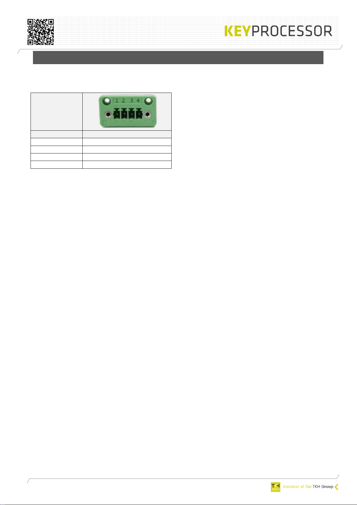
4.3 Powering the Apollo
Connected the 48VDC to the green 4-way screw connector at the back of the Apollo.
When the 48VDC power is present and connected to the Apollo, the 12V and 24V LEDs will
become active immediately.
Apollo front:
Pin nr.
DC IN
1
V+
2
No function
3
Earth connection ⏚
4
V-
Page 9
5 Safety and detections
The Apollo is provided of several internal protections. An event will be generated and sent to
iProtect™ (or SNMP) when an internal protection is activated.
The internal protections of the Apollo are:
• Internal 12VDC
• Internal 24VDC
• Each section is provided with a polyfuse (12- and 24VDC)
• The Apollo features an onboard temperature sensor to measure the temperature of the
Apollo itself.
• Front power (back battery)
• Power failure
• Supervised inputs: a message will be send to iProtect/SNMP when an overload or short-
circuit is detected on the 12/24VDC
• Digital I/O: a message will be send to iProtect/SNMP when an overload or short-circuit
is detected on the 12/24VDC
Page 10
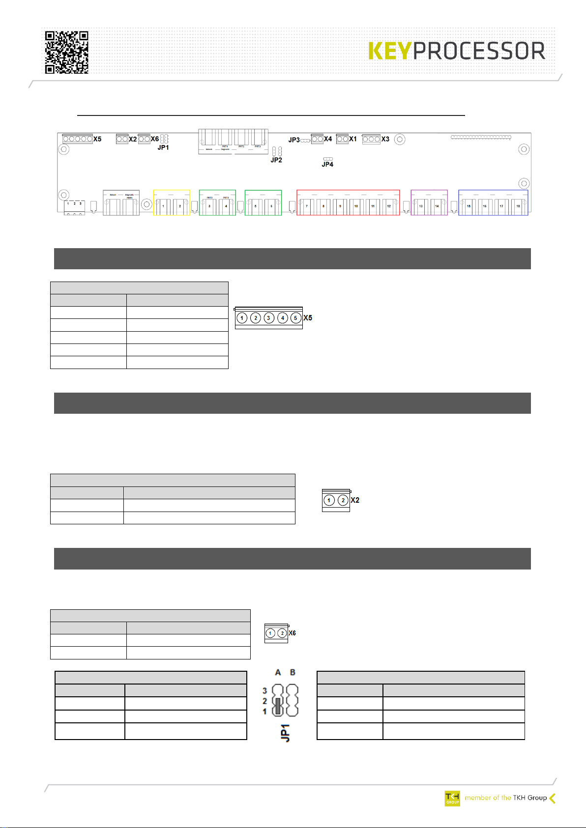
6 Internal connector and jumper settings
Picture 1: Apollo PCB
6.1 Power connection
X5 – Power connector
Pin number
Description
1
Ground
2
GND Ext.
3
+ (DC) Ext.
4
GND int.
5
+24VDC int.
6.2 Door lock overrule
In case the door lock doesn’t open on presenting a valid badge to the card reader and/or when
an operator can’t open the door remotely anymore, the Apollo has a lock overrule function.
A cable must be connected to X2 on the Apollo board, depending of the door lock.
X2 - Door lock overrule
Pin number
Description
1
Door lock 1 (switching to GND)
2
Door lock 2 (switching to GND)
6.3 Lock voltage
When using an external VDC power supply, you don’t have to set the jumpers.
X6 - External lock voltage
Pin number
Description
1
+VDC NC - Door lock
2
+VDC NO - Door lock
JP1 - Internal lock voltage (NO)
JP1 - Internal lock voltage(NC)
Pin number
Description
Pin number
Description
3A
+12VDC
3B
+12VDC
2A
C
2B
C
1A
+24VDC (default)
1B
+24VDC
Page 11

6.4 Internal supervised output 1 / FAN
When needed, the Apollo can be provided of a cooling fan.
JP3 – X4 function
Pin number
Description
1
Relay (supervised output 1)
2
C
3
+12VDC (FAN) (default)
X4
Pin number
Description
1
+ (e.g. FAN)
2
GND
6.5 Internal supervised output 2
When needed, the Apollo can be provided of a 115db PIEZO Buzzer.
X1 – internal supervised output 2
Pin number
Description
1
+ (PIEZO Buzzer)
2
GND
6.6 Supervised output voltage
The voltage which is needed on the supervised outputs can be set by a jumper (12/24VDC).
JP4 – supervised output voltage
Pin number
Description
1
+24VDC (default)
2
C
3
+12VDC
6.7 Walk test
When using intrusion detectors you have the possibility to use a walk test function.
JP2 - Walk test (NO)
JP2 - Walk test (NC)
Pin number
Description
Pin number
Description
3A
12VDC
3B
12VDC
2A
C
2B C 1A
GND (default)
1B
GND
Page 12

6.8 Power connection controller board
X3 – Controller board
Pin number
Description
1
Earth
2
GND
3
+24VDC
Page 13

7 Smart cabinet security: System setup
1 Sensor
7 Ethernet
1 Server
1 Card reader
1 Intrusion detector
1 Water sensor
1 Swing handle lock
1 Client PC
1 Smoke detector
1 Flash light
1 Siren
1 Door sensor
1 Apollo
1 SNMP management
Legenda
Symbol Amount Description
Apollo configuration
iProtect™ server
Apollo cabinet security
Ethernet TCP/IP
Apollo hardware
Plug and Play; Prefab cabling
SNMP Management server
Picture 1: system setup
Page 14

7.1 Sockets and port overview
The following network sockets are used when connecting an Apollo into the network,
communicating with iProtect™ and a SNMP Management server:
Port
TCP
UDP
Description
Communication
Ethernet
speed
80
Hypertext Transfer Protocol (HTTP)
10/100Mb
Full duplex
161
UDP
Simple Network Management
Protocol (SNMP)
162
TCP
UDP
Simple Network Management
Protocol Trap (SNMPTRAP)
19999
TCP
Debug
Applet → Controller
20100
TCP
iProtect™ communication
Controller → iProtect™
20201
TCP
iProtect™ communication
iProtect™ → Controller
20600
TCP
Debug
Applet → Controller
Remark! Testing the (Ethernet) connection by using Ping is necessary when
commissioning the hardware.
Page 15

8 Apollo Smart cabinet security
Plug and Play: Prefab cabling
Warning! Connecting peripherals to the Apollo should be performed carefully. Almost all ports
of the Apollo feature 12V and 24V sockets. When not connecting peripherals on a
appropriate way to the Apollo, it can cause irreparable damage to the peripherals.
Read also the well-made labels on the wiring through and adjust the colors of the
cables to the correct section. On the labels is shown precisely what port the cable
must be plugged.
8.1 Power connector
The Apollo is provided with a 3 and 4 pin removable screw connector.
The functionality of the 3-pin screw connector on the front of the Apollo has been canceled
with the use of 48VDC.
Use the 4-pin connector connection on the rear of the Apollo.
Apollo front:
Symbol
Function
⏚
None
-
None
+
None
Apollo rear
48VDC
connection:
Pin nr.
DC IN
1
V+ 2 No function
3
Earth connection ⏚
4
V-
Page 16

8.2 Led status
The Apollo is provided of two general status LEDs.
8.3 Controller: gray section
The Apollo is provided with two controller ports. The left port (gray section) is a standard 10-
100Mb Ethernet port. The right port is a console (diagnostic) port.
Apollo
front:
Port
nr.
Pin-
out
TIA/EIA-568-B
Cable color
TCP/IP Ethernet
10-100Mb
1
White/orange
TX+
2
Orange
TX-
3
White/green
RX+
4
Blue - 5
White/blue
-
6
Green
RX-
7
White/brown
-
8
Brown
-
Port
nr.
Pin-
out
TIA/EIA-568-B
Cable color
Console
1
White/orange
GND
2
Orange
-
3
White/green
-
4
Blue
TXD
5
White/blue
RXD
6
Green
-
7
White/brown
GND
8
Brown
GND
8.3.1 Cable length
See table below for the maximum cable length, used for this section:
Symbol
TIA/EIA-568-B
Cable color
Type
Maximum cable length
Network
TCP/IP
100m
Console
RS232
15m
Apollo front:
LED
Active
Function
S1
Permanent On
Internal fuses and measurements are OK
S2
Permanent On
Link with iProtect is OK
Page 17

8.4 Sensors: yellow section
The Apollo is provided with two sensor(bus) ports. On both ports you can connect multiple
kpSensors, up to a maximum of 20 id’s (calculated over both ports).
Each measurement will get an id.
Example: one kpSensor device measures ‘temperature AND Humidity’, two id’s will be used.
Several measurements can done, depending on sensor type (e.g. temperature, humidity, Air
flow, etc.). Visit our website and check for the supported kpSensor devices:
www.keyprocessor.com/apollo
It is also possible to connected two 0-10V devices instead of kpSensors. The devices will be
powered from the Apollo.
Apollo front:
Port
nr.
Pinout
TIA/EIA-568-B
Cable color
Sensor
Comment
12VDC
Polyfuse
24VDC
Polyfuse
1
1
White/orange
GND
500mA
200mA
2
Orange
Loop 8
ADC 0-10V
3
White/green
12VDC
Max. 500mA
4
Blue
kpSensor
Max. 500mA
5
White/blue
GND
6
Green
24VDC
Max. 200mA
7
White/brown
-
8
Brown
Reset function**
Port
nr.
Pinout
TIA/EIA-568-B
Cable color
Sensor
Comment
2
1
White/orange
GND
2
Orange
Loop 9
ADC 0-10V
3
White/green
12VDC
Max. 500mA
4
Blue
kpSensor
Max. 500mA
5
White/blue
GND
6
Green
24VDC
Max. 200mA
7
White/brown
-
8
Brown
Reset function**
** When using an 110-230VAC power supply, you can reset the Apollo from the front side.
When creating a loop between port 1 and port 2, the Apollo will restart.
8.4.1 Cable length
See table below for the maximum cable length, used for this section:
Note! Please use only one bus when using the kpSensor. A combination of kpSensors
combined over port 1 and 2 is not possible.
Port
nr.
TIA/EIA-568-B
Cable color
Type
Maximum cable length
1 - 2
Sensor
kpSensor
30m
Page 18

8.5 Reader and door I/O: green section
The Apollo is provided with two reader ports and two door I/O ports.
Apollo front:
Por
t
nr.
Pin
-
out
TIA/EIA-568-B
Cable color
Reader 1
Comment
Option
Option
Option
3
1
White/orange
RXB
2
Orange
RXA
3
White/green
TXB
4
Blue
+12VDC
Max. 250mA
5
White/blue
Orbit sense
6
Green
TXA
7
White/brown
GND
8
Brown
GND
Por
t
nr.
Pin
-
out
TIA/EIA-568-B
Cable color
Door I/O 1
Comment
Option
Option
Option
4
1
White/orange
Input 1
Digital input to GND
2
Orange
Input 2
Digital input to GND
3
White/green
Input 3
Digital input to GND
4
Blue
Lock control
Max. 1A (polyfuse)
12/24VDC
48VDC
NO/NC
5
White/blue
6
Green
Input 4
Digital input to GND
7
White/brown
GND
8
Brown
GND
Por
t
nr.
Pin
-
out
TIA/EIA-568-B
Cable color
Reader 2
Comment
Option
Option
Option
5
1
White/orange
RXB
2
Orange
RXA
3
White/green
TXB
4
Blue
+12VDC
Max. 250mA
5
White/blue
Orbit sense
6
Green
TXA
7
White/brown
GND
8
Brown
GND
Por
t
nr.
Pin
-
out
TIA/EIA-568-B
Cable color
Door I/O 2
Comment
Option
Option
Option
6
1
White/orange
Input 1
Digital input to GND
2
Orange
Input 2
Digital input to GND
3
White/green
Input 3
Digital input to GND
4
Blue
Lock control
Max. 1A (polyfuse)
12/24VDC
48VDC
NO/NC
5
White/blue
6
Green
Input 4
Digital input to GND
7
White/brown
GND
8
Brown
GND
Page 19

8.5.1 Cable length
See table below for the maximum cable length, used for this section:
Port
nr.
TIA/EIA-568-B
Cable color
Type
Maximum cable length
3
Reader 1
RS485
50m
4
Door I/O 1
I/O
50m
5
Reader 2
RS485
50m
6
Door I/O 2
I/O
50m
8.5.2 Led status
The reader communication and the lock output are indicated by two LEDs.
LED
Function
R1
When card reader 1 communicates, LED R1 is active
L1
When door lock 1 is active, LED L1 is active
R2
When card reader 2 communicates, LED R2 is active
L2
When door lock 2 is active, LED L2 is active
Page 20

8.6 Supervised inputs: red section
The Apollo is provided with 6 supervised inputs. These inputs can be used to connect intrusion, or smoke detectors. The detectors will be powered by the Apollo.
There is also an option to start a Walk test or to send a reset to the detectors of this section.
Apollo front:
Port
nr.
Pin-
out
TIA/EIA-568-B
Cable color
Supervised
I/O
Comment
Comment
Option
12VDC
Polyfuse
24VDC
Polyfuse
7
1
White/orange
GND
500mA
200mA
2
Orange
Loop 0
0-60K ohm
3
White/green
Reset
Output to
GND
4
Blue
+24VDC
Max. 200mA
5
White/blue
+12VDC
Max. 500mA
6
Green
Walk test
Max. 500mA
Output to
12VDC/GND
7
White/brown
GND 8
Brown
GND
Port
nr.
Pin-
out
TIA/EIA-568-B
Cable color
Supervised
I/O
Option
Comment
Option
8
1
White/orange
GND 2
Orange
Loop 1
0-60K ohm
3
White/green
Reset
Output to
GND
4
Blue
+24VDC
Max. 200mA
5
White/blue
+12VDC
Max. 500mA
6
Green
Walk test
Max. 500mA
Output to
12VDC/GND
7
White/brown
GND 8
Brown
GND
Port
nr.
Pin-
out
TIA/EIA-568-B
Cable color
Supervised
I/O
Comment
Comment
Option
9
1
White/orange
GND 2
Orange
Loop 2
0-60K ohm
3
White/green
Reset
Output to
GND
4
Blue
+24VDC
Max. 200mA
5
White/blue
+12VDC
Max. 500mA
6
Green
Walk test
Max. 500mA
Output to
12VDC/GND
7
White/brown
GND 8
Brown
GND
Port
nr.
Pin-
out
TIA/EIA-568-B
Cable color
Supervised
I/O
Comment
Comment
Option
10
1
White/orange
GND 2
Orange
Loop 3
0-60K ohm
3
White/green
Reset
Output to
GND
4
Blue
+24VDC
Max. 200mA
5
White/blue
+12VDC
Max. 500mA
6
Green
Walk test
Max. 500mA
Output to
12VDC/GND
7
White/brown
GND
8
Brown
GND
Page 21

Port
nr.
Pin-
out
TIA/EIA-568-B
Cable color
Supervised
I/O
Comment
Comment
Option
12VDC
Polyfuse
24VDC
Polyfuse
11
1
White/orange
GND
500mA
200mA
2
Orange
Loop 4
0-60K ohm
3
White/green
Reset
Output to
GND
4
Blue
+24VDC
Max. 200mA
5
White/blue
+12VDC
Max. 500mA
6
Green
Walk test
Max. 500mA
Output to
12VDC/GND
7
White/brown
GND
8
Brown
GND
Port
nr.
Pin-
out
TIA/EIA-568-B
Cable color
Supervised
I/O
Comment
Comment
Option
12
1
White/orange
GND 2
Orange
Loop 5
0-60K ohm
3
White/green
Reset
Output to
GND
4
Blue
+24VDC
Max. 200mA
5
White/blue
+12VDC
Max. 500mA
6
Green
Walk test
Max. 500mA
Output to
12VDC/GND
7
White/brown
GND 8
Brown
GND
Remark! When the Apollo detects a short circuit- or an overload on this section, a messages will be
send to iProtect™
8.6.1 Cable length
See table below for the maximum cable length, used for this section:
Port
nr.
TIA/EIA-568-B
Cable color
Type
Maximum cable length
7 - 12
Environment
input
I/O
50m
8.6.2 Led status
The voltage on the supervised inputs are indicated by two LEDs.
LED
Function
12V
When 12VDC is present, LED 12V will be active.
When there is an overload or short circuit, the LED will be deactivated
24V
When 24VDC is present, LED 24V will be active.
When there is an overload or short circuit, the LED will be deactivated
Page 22

8.7 Supervised outputs: violet section
The Apollo is provided with 2 supervised outputs. These outputs can be used to connect a siren
or a flash light. The detectors will be powered by the Apollo.
Apollo front:
Port
nr.
Pin-out
TIA/EIA-568-B
Cable color
Supervised I/O
Comment
Option
13
1
White/orange
GND
2
Orange
Loop 6
0-60K ohm
3
White/green -
4
Blue
High Power output
Max. 1A (polyfuse)
12/24VDC
5
White/blue
6
Green -
7
White/brown
GND
8
Brown
GND
Port
nr.
Pin-out
TIA/EIA-568-B
Cable color
Supervised I/O
Comment
Option
14
1
White/orange
GND
2
Orange
Loop 7
0-60K ohm
3
White/green -
4
Blue
High Power output
Max. 1A (polyfuse)
12/24VDC
5
White/blue
6
Green -
7
White/brown
GND
8
Brown
GND
8.7.1 Cable length
See table below for the maximum cable length, used for this section:
Port nr.
TIA/EIA-568-B
Cable color
Type
Maximum cable length
15 - 16
Environment input
I/O
50m
8.7.2 Led status
The supervised outputs are indicated by two LEDs.
.
LED
Function
SO1
When supervised output 1 is active, LED SO1 is active
SO2
When supervised output 1 is active, LED SO2 is active
Page 23

8.8 Digital I/O: blue section
The Apollo is provided of 8 digital I/Os. The detectors (e.g. water detector) will be powered by
the Apollo.
Remark! When the Apollo detects a short circuit- or an overload on this section, a messages will be
send to iProtect™
8.8.1 Cable lenght
See table below for the maximum cable length, used for this section:
Apollo front:
Port
nr.
Pin-out
TIA/EIA-568-B
Cable color
Digital
I/O
Comment
Comment
12VDC
Polyfuse
24VDC
Polyfuse
15
1
White/orange
GND
500mA
200mA
2
Orange
Loop 1
Max. 1A +28VDC
Digital input to GND
3
White/green
GND
4
Blue
+24VDC
Max 200mA
5
White/blue
+12VDC
Max. 500 mA
6
Green
Loop 2
Max. 1A +28VDC
Digital input to GND
7
White/brown
GND
8
Brown
GND
Port
nr.
Pin-out
TIA/EIA-568-B
Cable color
Digital
I/O
Comment
Comment
16
1
hite/orange
GND
2
Orange
Loop 3
Max. 1A +28VDC
Digital input to GND
3
White/green
GND
4
Blue
+24VDC
Max 200mA
5
White/blue
+12VDC
Max. 500mA
6
Green
Loop 4
Max. 1A +28VDC
Digital input to GND
7
White/brown
GND
8
Brown
GND
Port
nr.
Pin-out
TIA/EIA-568-B
Cable color
Digital
I/O
Comment
Comment
17
1
White/orange
GND
2
Orange
Loop 5
Max. 1A +28VDC
Digital input to GND
3
White/green
GND
4
Blue
+24VDC
Max 200mA
5
White/blue
+12VDC
Max. 500mA
6
Green
Loop 6
Max. 1A +28VDC
Digital input to GND
7
White/brown
GND
8
Brown
GND
Port
nr.
Pin-out
TIA/EIA-568-B
Cable color
Digital
I/O
Comment
Comment
18
1
White/orange
GND
2
Orange
Loop 7
Max. 1A +28VDC
Output only!
3
White/green
GND
4
Blue
+24VDC
Max 200mA
5
White/blue
+12VDC
Max. 500mA
6
Green
Loop 8
Max. 1A +28VDC
Digital input to GND
7
White/brown
GND
8
Brown
GND
Port nr.
TIA/EIA-568-B
Cable color
Type
Maximum cable length
15 -18
Environment input
I/O
50m
Page 24

8.8.2 Led status
The voltage on the digital inputs are indicated by two LEDs.
LED
Function
12V
When 12VDC is present, LED 12V will be active.
When there is an overload or short circuit, the LED will be deactivated
24V
When 24VDC is present, LED 24V will be active.
When there is an overload or short circuit, the LED will be deactivated
Page 25

9 Apollo diagnostic menu
9.1 Connecting to the Apollo console port
An installation diagnosis is possible with a pc/laptop.
For a diagnosis with a pc or laptop there is an installation diagnosis menu, ‘Polyx Diags'. It is
not necessary to download all settings via a user interface. After connecting the hardware,
without an exchange being present, it can be checked, locally via a simple terminal program,
whether all hardware is operational.
There are many different programs, like Teraterm, which can emulate a VT100 terminal on a
PC. Using a simple laptop, diagnostics can be logged in via the serial port in the Apollo.
Connect your PC for example to port “Console” from the Apollo. Use the adapter
shown below (available at Keyprocessor BV).
Open a terminal program and make a connection. (e.g. Tera term)
Select the COM-port of the PC connected to the Apollo.
Choose a baud rate of “115200”, Data ‘8 bit”, Stop ‘1 bit’, Parity ‘None’ and flow control
“none”.
9.2 Start diagnostic
When after starting-up the Apollo, the line ‘Hit any key within 5s to run diagnostics...’ appears
and a key is pressed within five seconds, then the diagnostics program is started.
The main menu has the following appearance:
Polyx Diags version V3.0.3
1) Environment settings
2) Test onboard I/O
3) Test RS422 devices (loopback)
4) Test profi-device Communications
5) Test Profi-device functionality
6) Clean nodemgr
7) Test Watchdog
8) Clean system
9) Clean /etc/rc.d/* to /etc/save.d/*
v) Version
p) Polyx menu
q) Start application
r) Restart system
Enter menu option:
Page 26

Note: Only options 1, 2, v, p, q and r are applicable for the installer.
• q: Close diagnostic program and start application
• r: Restart Apollo
9.3 Environment settings
If option 1 is selected from the main menu of the Diagnostics program, it’s possible to see and
set the environment options. The following options are relevant:
--- Environment settings ---
serial=12456749
mac address=00:1e:d1:10:1a:5d
ip=192.168.1.195
gateway=0.0.0.0
netmask=255.255.255.0
server=192.168.1.1
backup=0.0.0.0
port=0
dhcp=0
Hit any key to continue...
• ip: the IP-address of the Apollo
• gateway: the gateway address if the communication passes via a router
• netmask: for a distinction between the local Ethernet traffic and Ethernet traffic via a
router.
• server: the IP-address of the iProtect™ main server
• backup: the IP-address of the iProtect™ backup server
• port: port which is used for provisioning. (0=off and 6060=Default port)
• dhcp: enable or disable use of dhcp. 0=disabled 1=enabled
Screen: changing environment ip setting
--- Environment settings ---
Enter new environment setting :
> ip=192.168.1.195
Screen: changing environment ip setting
--- Environment settings ---
Enter new environment setting :
> ip=192.168.1.195
OK : <IP=192.168.1.195>
Hit any key to continue...
Note: to activate these settings reboot the system. Use option (r) and do not
restart the Apollo by discharging the voltage.
Page 27

9.4 Digital IO test
If option 2 is selected from the main menu of the Diagnostics program, the user can test
whether the connected equipment itself is functioning properly.
--- Digital IO Test ---
STATUS [z-x]: 0 0
YELLOW : 0.000 V 0.000 V
GREEN-1 [a] : 0 0 0 0 0
GREEN-2 [b] : 0 0 0 0 0
RED [c-d]: 1 1 3935 3935 3935 3935 3935 3935
PURPLE [e-f]: 0 3935 0 3935
BLUE [1-8]: 0 0 0 0 0 0 1 0
VOLTAGE : 12v 12.213 V 24v 27.523 V EXT 26.542 V
TEMP : 23.352 C
FUSE : 12V-RED=PASS 12V-BLUE=PASS 24V-RED=PASS 24V-BLUE=PASS
r) reload data
q) Goto the main menu
Enter menu option :
• Status: Status LED S0 and S1 can be (de)activated
• Yellow: Port 1-2: The values of the sensors will be displayed
• Green1: Port 4: the status of the 4 inputs are displayed. The output can be switched
using A
• Green2: Port 6: the status of the 4 inputs are displayed. The output can be switched
using B.
• Red: Port 7-12: status of the 6 monitored inputs are displayed. The outputs (walk-
test and reset) can be switched using C and D
• Purple: Port 13-14: status of the 2 monitored inputs are displayed. The outputs can be
switched using E and F
• Blue: Port 15-18: the status of the 7 inputs are displayed. The outputs can be
switched using 1-8
• Voltage: The internal and external voltages are displayed
• Temp: The board temperature of the Apollo is displayed
• Fuse: The statuses of the fuses are displayed. Pass=ok Fail=Overload or short circuit
Page 28

9.5 Version
If option v is selected from the main menu of the Diagnostics program, it’s possible to see the
software versions installed onto the Apollo:
Hardware information:
Board type: Polyx Version 2.a
--> Apollo V2 module installed
Versions installed on this board:
bootloader version: 5.k.2.b
Board power device: 2; External Powered
Polyx Diags version 3.0.3
uClinux version 3.3.0-uc0)(gcc version 4.4.1 (Sourcery G++ Lite 4.4-216) )
Built version:
Keyprocessor/apollo Version 4.0 -- Tue Jun 3 12:09:59 CEST 2014 Sourcery G++ Lite 4.4-216)
md5 fs : 7f4916973d05a4856b4faf9905151c00
md5 kernel: 181c322dc6a15ffb3c79ebdcfbc262ca
Polyx version: 04.00.11
Hit any key to continue...
9.6 Polyx menu
If option p is selected from the main menu of the Diagnostics program, it’s possible to test the
connection between the Apollo and de card reader(s)see and set the environment options. The
following options are relevant:
--- Polyx Test ---
Version : 04.00.11
Reader1 : I80: V1.2.18.1.0; 0013361009
Reader2 : I80P: V1.2.18.1.0; 0013362077
Reader3 : 26a59d40010000c6 : DS2438 (temperature,hygro)
Autodetect [a]: disabled
r) reload data
q) Goto the main menu
Enter menu option :
• Version: Software version number
• Reader1: Type-, firmware version- and serial number of device will be displayed*
• Reader2: Type-, firmware version- and serial number of device will be displayed*
• Reader3: Type- and serial number of device will be displayed*
• Autodetect: When pressing a, the Apollo automatically detects the connected type of
hardware.
* When entering this menu, a reader configuration is necessary to show the connected devices
automatically. When nothing is displayed automatically, please use option a.
Page 29

10 Technical specifications
Housing
Description:
19 inch, 1HE metal housing
Measurements:
482,6mm x 43.66 x 225.0 (W x H x D)
Weight
3,5Kg
Controller
Processor
Coldfire 5208, 32 bits, 166 MHZ, 159 MFLOPS
Memory
32 MByte DDR ram
Flash
16 MByte flash
Operating system:
uCLinux
Ethernet:
10/100 Mbit
Management information
SNMP and iProtect™
Consumption
Power consumption (no
load)
<7.0W
Power consumption
(maximum)
Single non-redundant power supply; max.
power supply rating 50.4W at >83% efficiency
(refer to output load de-rating curve)
Power supply 48VDC
Input:
Voltage
36-72VDC
Current
1.5A/48V
Output:
Voltage
24.0VDC
Current
2.1A
3-way connector:
Fuse
2A (Polyfuse protection)
Protection:
Overload
105 ~ 135% rated output power
Protection type : Hiccup mode, recovers
automatically after fault condition is removed
Over Voltage
31.5 ~ 37.5V/10% load
Protection type : Hiccup mode, recovers
automatically after fault condition is removed
Environment
Operating temperature:
-10°C to +60°C at sea level (refer to output load de-rating
curve)
Non operating altitude:
10.000m (35.000 ft.)
Operating altitude:
Operating altitude: Up to 3.000m (9.000 ft.),
max. ambient temperature is derated by
1° C per 300m above 900m
Working humidity:
20 ~ 90% RH non-condensing
Storage temp., humidity:
-20 ~ +85°C, 10 ~ 95% RH
Polyfuse
Type
PTC Fuse Case style
Thermal derating
At -10° C the hold current will increase to 130%
At +25° C no derating
At +60° C the hold current will reduced to 60%
Page 30

Certifications
CE compliant
EMC (electromagnetic
compatibility):
EN 55022 (2010) + AC (2011),
class B
EN 61000-3-2 (2006) + A1
(2009) + A2 (2009)
EN 61000-3-3:2008
Immunity:
EN 55024:2010
Low Voltage (Product safety):
EN 60950-1 (2006) + A11
(2009) + A1 (2010) + A12
(2011)
Hardware
Digital output
max. Voltage 28V; Open collector output; sinked current. Max.
current 1A
Digital input
Pull-up resistance 4k7
Environment input
value
0-60K ohm
Environment output
12- or 24VDC max. 1A (polyfuse); switched by relay; NO/NC)
Lock output
12- or 24VDC max. 1A (polyfuse); (switched by relay; NO/NC).
Output voltage
12VDC max. 500mA (polyfuse)
24VDC max. 200mA (polyfuse)
Connections
Sensor
(Yellow section)
kpSensor
max. 20 id’s
0-10V
max. 2
Card reader
(Green section)
RS485
max. 2
Door I/O
(Green section)
output
max. 2
input
max. 8
Environment inputs
(red section)
input
max. 6
Walk test
switching to GND/12VDC
Reset
switching to GND
Environment outputs
(Purple section)
output
max. 2
input
max. 2
Digital I/O
(Blue section)
output
1
input
max. 7
Cooling FAN
AXIAL FAN, 40MM, 21dBA
Indicators
LED
12x green LED
PIEZO Buzzer
115db (option)
Page 31

10.1 Output load de-rating curve
Page 32

11 Technical drawings
Drawing number
Description
72000400
571-1013 Temperature and Humidity sensor
72000401
571-5001 Water sensor
72000402
571-2001 Sirius Card reader I30
72000403
571-3040 Bosch ISC-BDL2-W12G dualtech motion detector
72000404
571-3016 Smoke detector
72000405
571-4010 Controlled relay, with 230Vac presence check
72000406
571-3020 Viper GLX supervised shock sensor
72000407
571-4002 Siren with beacon AS-271
72000408
571-2001 Sirius Card reader I80
72000409
571-2001 Sirius Card reader I80P
72000413
571-3040 Pyronix KX15DT dual technology motion detector
 Loading...