

VibWire-201-Pro User Manual 1
Model VibWire-101-Pro
Vibrating Wire Sensor Analyser
&
Data Recording Unit
Part No: VibWire-201-Pro
Advanced FFT Sensor Analyser
Advanced FFT Sensor Analyser
Advanced FFT Sensor AnalyserAdvanced FFT Sensor Analyser
Precision Temperature Readings
Precision Temperature Readings
Precision Temperature ReadingsPrecision Temperature Readings
User Pre-set VW Sensor Configurations
User Pre-set VW Sensor Configurations
User Pre-set VW Sensor ConfigurationsUser Pre-set VW Sensor Configurations
Sdi-12 & RS-485 Communication Ports
Sdi-12 & RS-485 Communication Ports
Sdi-12 & RS-485 Communication PortsSdi-12 & RS-485 Communication Ports
Daylight readable LCD display
Daylight readable LCD display Expansion Options
Daylight readable LCD display Daylight readable LCD display
Manufactured by Keynes Controls Ltd
Data logging to micro SD memory card
Data logging to micro SD memory card
Data logging to micro SD memory cardData logging to micro SD memory card
Up to 32 gb Storage
Up to 32 gb Storage
Up to 32 gb Storage Up to 32 gb Storage
Spreadsheet Format Data Files
Spreadsheet Format Data Files
Spreadsheet Format Data Files Spreadsheet Format Data Files
Real-time Clock
Real-time Clock
Real-time ClockReal-time Clock
Expansion Options
Expansion Options Expansion Options
- 16 x 4 Wire Inputs
- 16 x 4 Wire Inputs
- 16 x 4 Wire Inputs - 16 x 4 Wire Inputs
- 32 x 2 Wire Inputs
- 32 x 2 Wire Inputs
- 32 x 2 Wire Inputs - 32 x 2 Wire Inputs
Manufactured by KEYNES CONTROLS LTD
Tel: (0044) 118 327 6067
E-mail: sales@keynes-controls.com
VibWire-201-Pro User Manual 2
Features
Lightweight, Portable & Rugged
Compatible with most manufactures vibrating wire sensors
Real-time displays Freq (Hz), Digits (Hz2/1000), SI-Units, Spectra
FFT Spectral based algorithms for interference free measurements
Auto-resonance excitation 400 - 15 K Hz range - minimises sensor stress
Fully configured sensor operations
Large data storage - 100 million readings - SD Flash Cards to 32 Gb
Fast data recording - 1 sec to 1 hour logging intervals
No Vibrating Wire Sensor Prior operating conditions required
Expandable to 32 channels
SDI-12 and RS-485 ports for remote network connection
Optional radio interfaces for cable free operations
Firmware up gradable device - load software revisions with factory return
Benefits
Out the box solution for vibrating wire sensor measurements
Daylight readable LCD Display
Provides superior measurements by automatically reducing incorrect readings caused by noise sources
Customised FFT-based algorithm ensures readings are accurate and free from interferences
Real-time Sensor Spectra Display
No special cables or connectors required
No programming experience required to interface to 3rd party loggers and data acquisition systems..
Interfaces up to 32 channels using the MUX-16/32 Expansion unit.
High resolution—less than 0.001 Hz (industry standard is 0.1 Hz)
Low power consumption - Uses readily available AA battery life - 24 Hours continuous use
Suitable for laboratory testing and field measurement applications
Precision temperature and frequency measurements from vibrating wire sensors
Works with all RTD-temperature sensors regardless T0 resistance - 3 K, 10K etc
Free Data Storage and Display Applications Software -
Additional items commonly used with the VibWire-201-Pro Unit
MUX-16/32 Expansion Unit
This device is used to expand the number of sensor inputs
that can be used by the VibWire-201-Pro from a single
channel to 32 inputs.
This device can be powered directly from the
VibWire-201-Pro for stand-alone measurements.
USB-SDI12-Pro Media Converter
This device is used to connect the VibWire-201-Pro to a
Windows PC remotely across the SDI-12 digital network.
The USB-SDI12-Pro can be used to power the VibWire201-Pro for fixed monitoring applications
The device supports all of the Keynes Controls SDI-12
sensor and interfaces, including many 3rd party devices.
The USB-SDI12-Pro isolates the network devices from the
Windows PC USB port and protects it against possible
damage caused by sensor failures.
USB-485-Pro Media Converter
This device is used to connect RS-485 based intelligent
devices including the VibWire-201-Pro a Windows PC.
The device not only can power sensors on the network,
but also isolates the PC USB port from any possible device
failure in order to prevent damage to the host PC.
The device supports all of the Keynes Controls RS-485
sensor and interfaces, including many 3rd party devices.
©
Copyright 2016-2017 Keynes C ontrols Ltd
No part of this manual can be re produced in part, or in whole
without the permission of Keyne s Controls Ltd.

VibWire-201-Pro User Manual 3
Page Number Description
5 Hardware Features / Controls and Ports
6 Quick User Guide - Default Thermistor part numbers - Real-time Results - Adjusting the display
7 Fitting Batteries - Battery Life - MUX-16/32 Expansion Port - Initial Start-up Screen -Low Battery Effects - Setting the Real-time Clock
8 Real-time Results -
9
10 Technical Specifications
11 Pre-set Sensor Configurations
12 Channel Expansion Options
13 Number of Channels
14 Program Commands for scanning MUX-16/32 in 32 x 2 Wire mode (3rd party loggers )
15 Frequently Asked Questions
16 Sensor Configuration Example - Piezometer
17 Sensor Configuration Example - Piezometer
18 Q-Log - Quick User Guide
Auto-timeout / Real-time Clock.
Factor Default Settings Reset
VW Sensor Installation.
Saving New Parameters - Adjusting the Time
Initial Start-up Display - Frequency Results Display - Digits Results Screen - Natural Units (SI) - Spectra Display
Spectral Features.
Digital Network Selection
Device Port Selection - SDI-12 Network Connection - RS485 Network Connection (Using USB-SDI12-Pro or USB-485-Pro media converters)
Temperature Measurements - Associated Part No - Device Configuration Software - Common VW Sensor Thermistor Part Numbers
- Sources of Error - Calibration Factor Error - User Defined Stein-hart Hart Calibration Factors
- Sensor Information
- Downloading and installing device setup software - Automatically setting the real-time clock.
Pre-defined Thermistor Calibration Parameters (Steinhart-Hart Calibration factors)
Automatically setting the real-time clock.
- 16 x 4 Wire Expansion - 32 x 2 wire expansion
- Mux-16/32 Expansion Unit Configuration Options - MUX Channel Selection Menu Options
Data Recording - Data Recording Options - Data Recording Menu System
Program Commands for scanning MUX-16/32 in 16 x 4 Wire Mode
- Switching between 2 and 4 Wire Mode Operations under SDI-12 Commands
- VW201-Pro want communicate with 3rd party logger - Network ID Number - How fast can the VibWire-201-Pro make a measurement
- Where to download the Q-LOG Software - How to make a measurements using a PC without any programming experience
- MUX-16/32 Connection Options to the VibWire-201-Pro
Temperature Compensated Calibration Factors - Results in Natural (SI) Units
Process Option setting - Pre-set Sensor Configuration Settings - Simplified Calibration Factors
Temperature Compensated Calibration Factors - Results in Natural (SI) Units
Process Option setting - Thermistor Type
Pre-set Sensor Configuration Settings
Simplified Calibration Factors
Factory Default Settings -Sample Rate Options
- Logging Configuration Window - Scanning for Devices
External Power Supply -Device identifier strings
PC Data Acquisition - Start data recording
(VW201cal software)
(VW201cal software)
19 Technical Specifications
20 Examples Of Using RS-485/SDI-12 Commands
21 Data Record to Flash Memory Card
22 Worked Example - Spot Welded VW Strain gauge
23 Temperature Calibration Factors
24 PC based Water Level Recording with Barometric Correction.
25 Temperature Measurements
26 Sensor Problems and Diagnostics
27 Free Standing Strain Gauge
Changing the ID Number (address) - Start a measurement for Instrument on a network
Isolated Power Source
Diagnostics
Removing The Memory Card
Storing the menu option
Default Sample Rates
External Power Supply
Isolated USB Media Converters
Data into engineering units - simplified formula
Adding a new thermistor type - Calibration parameters and what they mean - Sample Calibration Factors
(VW201cal software)
Device USB Configuration Port - Connection to a Data Logger
Factory Set Steinhart Hart Calibration Factors
Testing the temperature measurements
- 22 Deg C fixed point - 3.3 K Ohm temperature test resistor
- 52 Deg C fixed point - 1 K Ohm temperature test resistor
Sensor Operating Characteristics
- VW strain gauge - Pre-tension gauge mounted onto a structure
- VW strain gauge - Failed or loose weld
29 APPENDIX-A Menu System Summary
32 APPENDIX-B Sample Calibration Data Sheets
VibWire-201-Pro User Manual 4
Important Figures
Figures Description
Fig 1 Hardware Features
Fig 3 Initial Start-up Screen - no sensor connected
Fig 7 & 8 Sensor Installation
Fig 9 Adjust results display screens
Fig 10 Fitting batteries
Fig 12 Setting the real-time clock
Fig 14 - 17 Results displays
Fig 18 - 19 VW sensor spectra
Fig 20 - 21 Device Port Selection
Fig 22 SDI-12 network connection - USB-SDI12-Pro Media Converter
Fig 23 RS-485 network connection - USB-485-Pro Media Converter
Fig 24 - 25 VW201cal Software - Calibration Factors Entry Window
Fig 26 32 x 2 Wire Expansion with the MUX-16/32 Unit
Fig 27 16 x 4 Wire Expansion with the MUX-16/32 Unit
Fig 28 MUX-16/32 Control Menu System.
Fig 29 Data Recording Menu System
Fig 31 MUX-16/32 Output Port Connections for 32 x 2 Wire Mode.
Fig 32 MUX-16/32 Output Port Connections for 16 x 4 Wire Mode.
Fig 33-35 32 x Frequency / 32 x Temperature / 16 x 4 Expansion Unit Wiring Options.
Fig 39 Select individual MUX-16/32 Channel Menu System
Fig 41 VW201cal Software - Example Calibration (Frequency) factor configuration Window.
Fig 43 Preset Sensor selection Menu System
Fig 45 SDI-12 port pin-outs - USB-SDI12-Pro and VibWire-201-Pro
Fig 46 Q-LOG Configuration Window - Data Logging - PC Port Network Type Selection.
Fig 48 Scanning for Devices - Q-Log Window.
Fig 49 Q-LOG Devices List Window
Fig 50 Q-LOG Start Data Acquisition Window
Fig 53 External Power Supply
Fig 54 Recording Interval Menu Options
Set number of channels to scan.
Product Changes
VibWire-201-Pro demonstrating the ability
to calculate and display a real-time
vibrating wire sensor spectra.
Keynes Controls Ltd has an on-going policy of design review and reserves the right to amend
the design of their product and this instruction manual without notice
VibWire-201-Pro User Manual 5
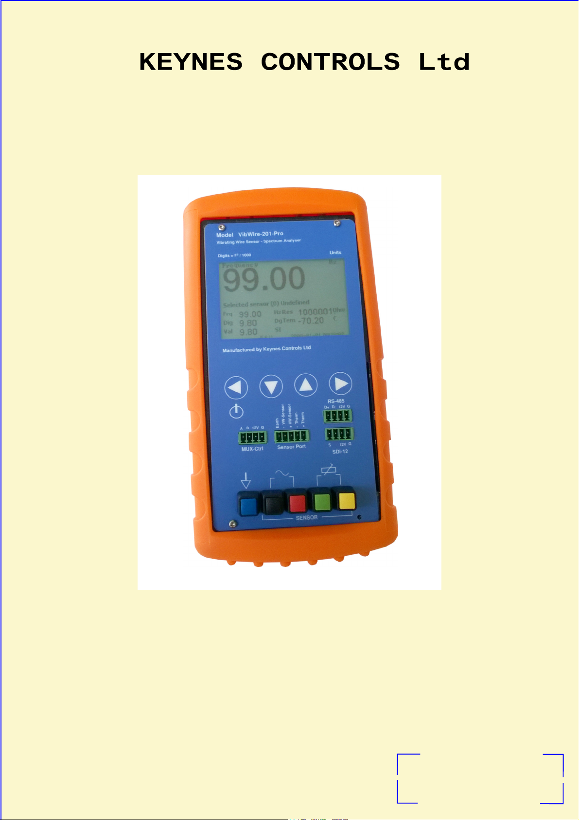
Hand Held VW Logger Unit with FFT Analyser
Hand Held VW Logger Unit with FFT Analyser
Hand Held VW Logger Unit with FFT Analyser Hand Held VW Logger Unit with FFT Analyser
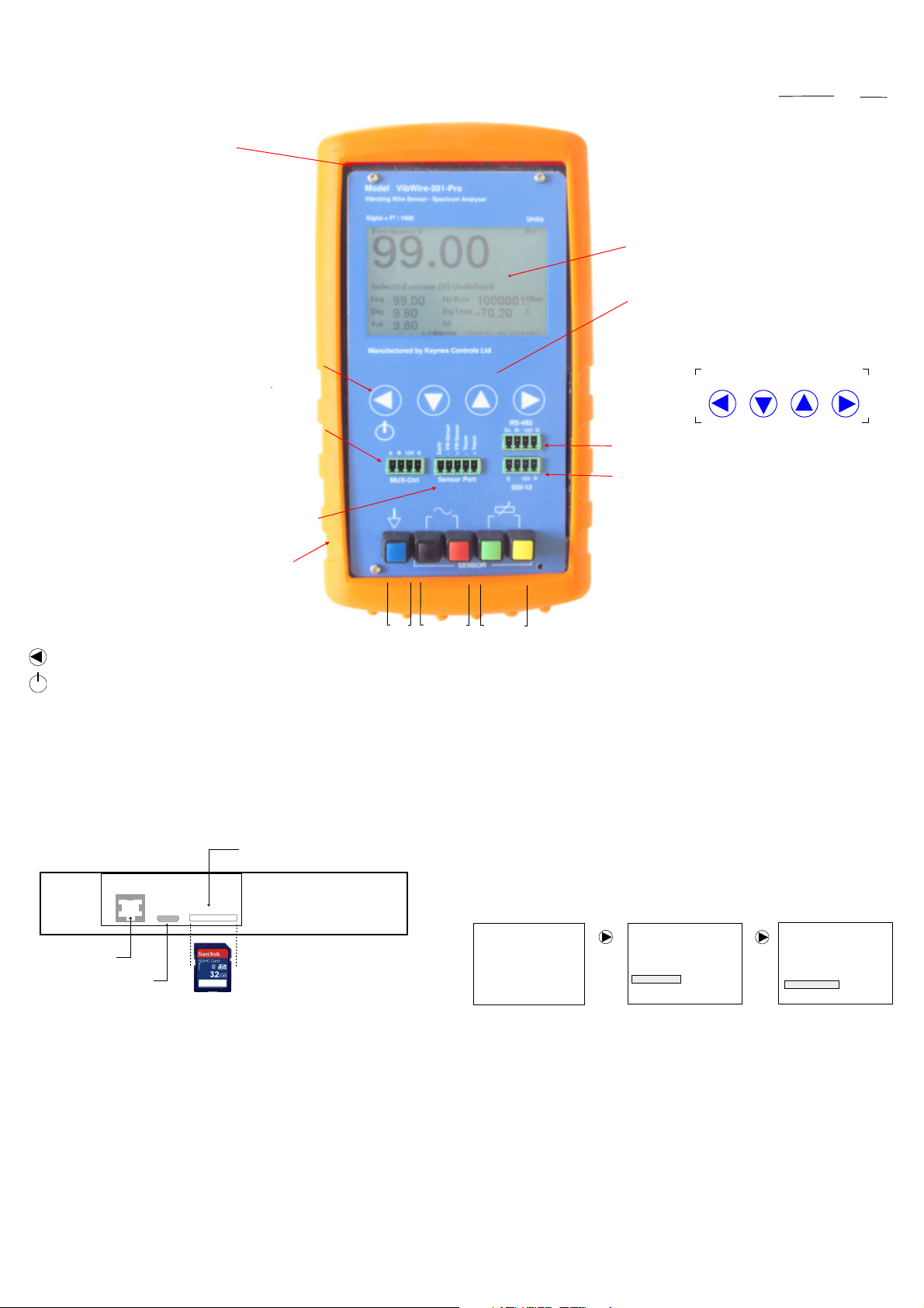
Hardware Features
Fig-1
Carbon fibre reinforced
ABS plastic enclosure
Power On
To power on the VibWire-201-Pro unit, hold and press the On/Off
button for 2 seconds. The device will initiate and start a measurement
operation.
The device will initialise using the last defined senso
Power Off
Hold and press the On/Off button and the device will power off
Powering on the Unit
Press and hold for 2 seconds the ‘Menu Out’ button. The device will
power on and the ‘Start-up Screen will be displayed. Repeat the
operation to power off the device.
Menu-Out
On/Off Button
r.
.
Menu-In &
Power On/Off
Button
MUX-16/32 Control Port
Sensor Port
Compatible with the
VW101 & VW108 units
Rubber protective
boot cover
Earth
Frequency
Signal connection Posts
Port
Temperature
Port
Calculations
Keynes Controls use the following calculation
Digits = Frequency 2
1000
Day Light Readable LCD Display
The LCD display is clear to read in most lighting conditions. A
back light is available for low level light environments. Three
levels or display brightness can be ‘User’ assigned.
Back light - LCD Screen
Options for High , Low, Off.
User Defined Sensors - 20 options
Use the Windows Configuration software to assign
sensor details.
Menu Control Buttons
Use the Menu-In and Menu-Out buttons to select the different
menu systems.
User the ‘Up’ and ‘Down’ menu keys to select the menu items.
RS-485 network port
SDI-12 network port
The 4 wire sensor port mounted at the bottom of the instrument is
used a general sensor test port. Bare sensor wires can be simply
connected directly into the spring terminal posts.
4 Wire Sensor Inputs + Earth
Spring Terminal Post Connectors
Real-time Clock
Temperature compensated real-time clock accurate to 50 ppm
/ Deg C.
(Hz2)
1000
Menu-InMenu-Out Down Up
Automatic Time-out
The VibWire-201-Pro will power down automatically after 30 minutes of unattended operation, unless configured to make measurements.
Protective Case
The case for the VibWire-201-Pro is manufactured from carbon fibre reinforced
ABS plastic. This makes the case highly safe from accidental damage.
The rubber boot prevents provides additional protection from the wear and tare
of site work. A rear stand enables the device to free stand while in operation.
SDHC flash memory
card slot.
Factory Default Setting Reset
Select the ‘Reset Defaults’ option shown below to reset the device to its factory
settings. The image below shows the menu operations required to undertake
this task.
Ethernet Port
Micro-USB Port
(Type B)
Fig-2
Frequency
2534.86
Selected Sensor
Frq
Hz
Res
Dg
SI
Tem
2016-01- 20 08 :40::17
6
3003.56
24.89
2534.86
Dig
6424.95
992.28
Val
Ohm
C
Menu-In
Hz
Sensor No
Logger
Multiplexe r
Remote
System
Main Menu
Menu-In
System
Set Time and Date
Speaker O N/OFF
Backlight
Info
Reset De faults
Ethernet Port
The Ethernet port is currently not used in the VibWire-201-Pro and has been added for future expansion.
Micro-USB Port (Type B)
The micro-USB port is used to configure the VibWire-201-Pro and to download data. Use the VW201pro configuration software tool assign sensor configuration
information into the instrument.
SDHC Flash Memory
The VibWire-201-Pro supports a single SDHC memory card slot. The memory card has to be pre-formatted before use.
The maximum size memory card currently supported is 32 Gb.
VibWire-201-Pro User Manual 6
Quick User Guide
VW Sensor Installation
The instructions shown in the Quick User Guide presumes that the batteries have
already been installed into the device and a vibrating wire sensor is ready for
testing.
The VibWire-201-Pro will operate with any sensor manufactures device.
The VibWire-201 comes pre-configured with default temperature sensor calibration
factors defined. The pre-set temperature sensor calibration factors are based on
a 3 K Ohm @ 25 Deg C device. The following sensor part numbers all use the
same calibration settings.
1000001
-70.20
2016-01-20 08:40::17
Hz
Ohm
C
Default Thermistor Part Numbers
YSI 44005
Vishay 1C 3001 B3
RS Part no: 151-215
1. Power On The VibWire-201-Pro.
Press and hold the ‘Power On’ for 2 seconds.
and with no sensor connected the default
Frequency display is shown opposite.
Frequency
99.00
Selected Sensor
Frq
Dig
Val
99.00
9.80
9.80
Hz
Res
Tem
Dg
SI
6
Fig-3 Initial Start-up Screen
Default screen with no sensor attached.
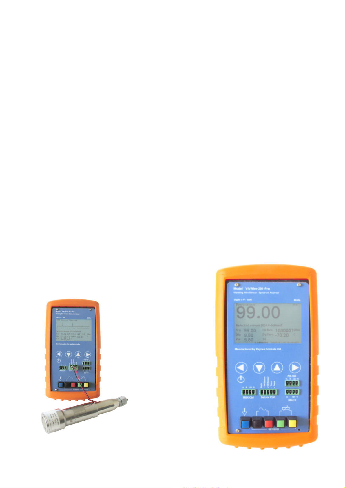
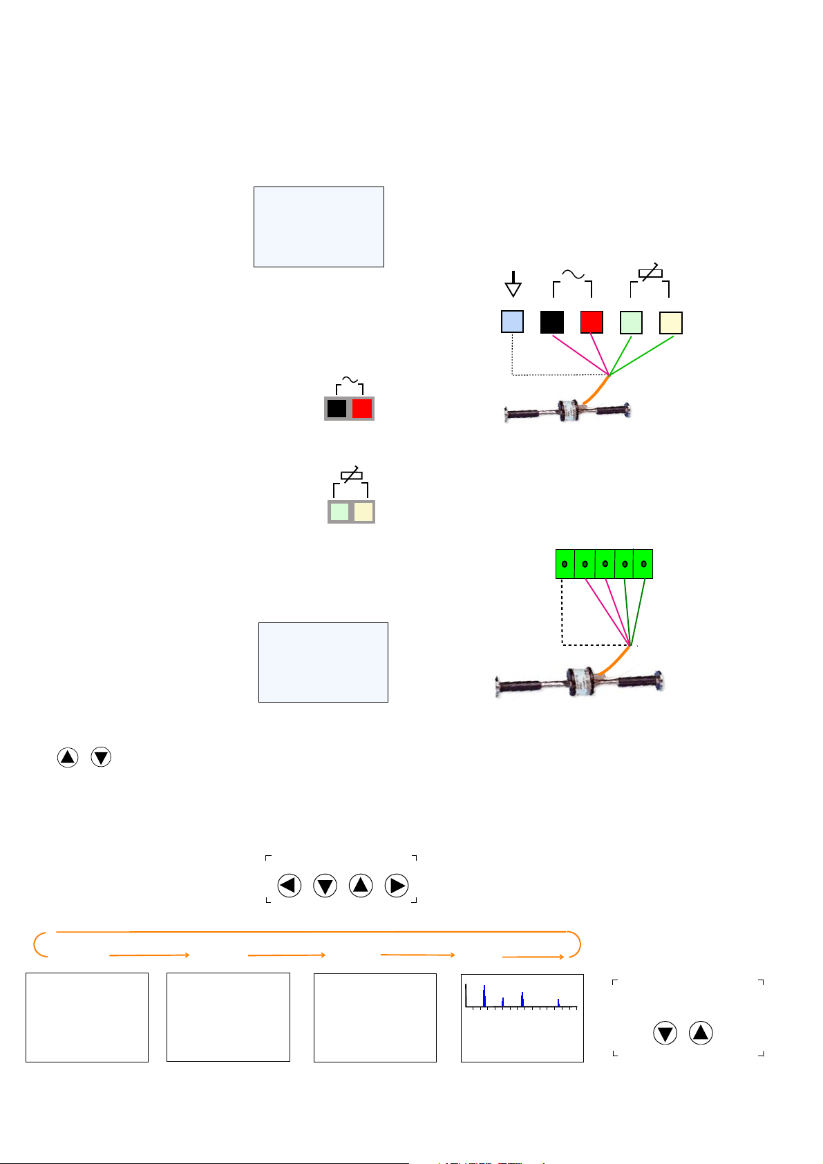
2. Connect a vibrating wire sensor to the device
Connect a single sensor to either the 5 pin terminal block input port or directly onto the
sensor port mounted at the bottom of device using the spring loaded terminal posts..
Connect the frequency output signal from the sensor to the red and
black terminal posts.
Frequency
Fig-4
Input Signal
Connection
The VibWire-201-Pro supports full 4 wire sensor operations. The device
measures frequency and temperature from any suitable vibrating wire sensor.
Connect a Vibrating Wire sensor to the 5 pin ‘Sensor Input’ port or directly to
the spring return termination posts mounted at the bottom of the unit.
1. Connect the sensor coil to the ‘Frequency Input’ port.
2. Connect the sensor thermistor (temperature) sensor to the ‘Temperature
Input’ port.
3. Use the VW201cal.exe software to define thermistor calibration factors.
Figures 7 and 8 show how to connect a vibrating wire sensor to the device.
Sensors connected to the spring loaded terminal posts
Fig-7
Earth
Frequency
Input
Frequency
Signal
Coil
+-
Temperature
Input
Sensor
Terminal
Posts
Sensors connected to the Sensor Port
Connect the vibrating wire sensor thermistor (temperature sensor)
to the green and yellow terminal posts.
Thermistor
Fig-5
Input Signal
Connection
3. Real-time Results
As soon as the vibrating wire sensor is connected to the VibWire-201-Pro then the measurements
will be displayed on the display.
3003.56
24.89
2016-01-20 08:40::17
Ohm
C
Hz
A typical display screen is shown opposite.
Fig-6
Frequency
2534.86
Selected Sensor
Frq
Dig
Val
2534.86
6424.95
992.28
Hz
Res
Tem
Dg
SI
6
3. Use the ‘Up’ and ‘Down’ keys to switch between Hz, Digits and Spectra.
Down
Up
The SI unit display remains blank until configured.
Adjusting the display
Use the keyboard ‘Up’ and ‘Down’ arrow keys to adjust the results display screens.
The display screen will be change as the
Up and Down keys are pressed.
Menu-InMenu -Out Down Up
- VW Sensor
Earth
Frequency
Signal
Coil
- Thermistor
+ Thermistor
+VW Sensor
Sensor Port
Thermistor
temperature
sensor
Fig-8
Fig-9
Frequency
Frequency
2534.86
Selected Sensor (3) EDS-20
Frq
Dig
Val
2534.86
6424.95
992.28
Hz
Dg
SI
Res
Tem
2016-01-20 08 :40::17
6
3003.56
24.89
Hz
Ohm
C
Digits
Digits
6424.95
Selected Sensor (3) EDS-20
Frq
Dig
Val
2534.86
6424.95
992.28
Hz
Dg
SI
Res
3003.56
Tem
2016-01-20 08 :40::17
6
24.89
D
Ohm
C
The results shown above are obtained using an Encardio-rite EDS-20
vibrating wire pressure sensors.
SI Units
Sensor
992.28
Selected Sensor (3) EDS-20
Frq
Dig
Val
2534.86
683.929
992.28
Hz
Dg
SU
Res
3003.56
Tem
2016-01-20 08 :40:17
6V
24.89
Nat Units
Ohm
C
Spectra
FFT Sensor Spectra
6 10 11
2534.86
6424.95
992.28
7
Hz
Dg
SI
0 1 2 3 4 5
Selected Sensor (3) EDS-20
Frq
Dig
Val
KHz
Res
Tem
6
12
13
3003.56
24.89
2016-01-20 08:4 0::17
14
Ohm
C
Use the Up and Down arrow keys
15
to switch between the results screens
Down Up
VibWire-201-Pro User Manual 7
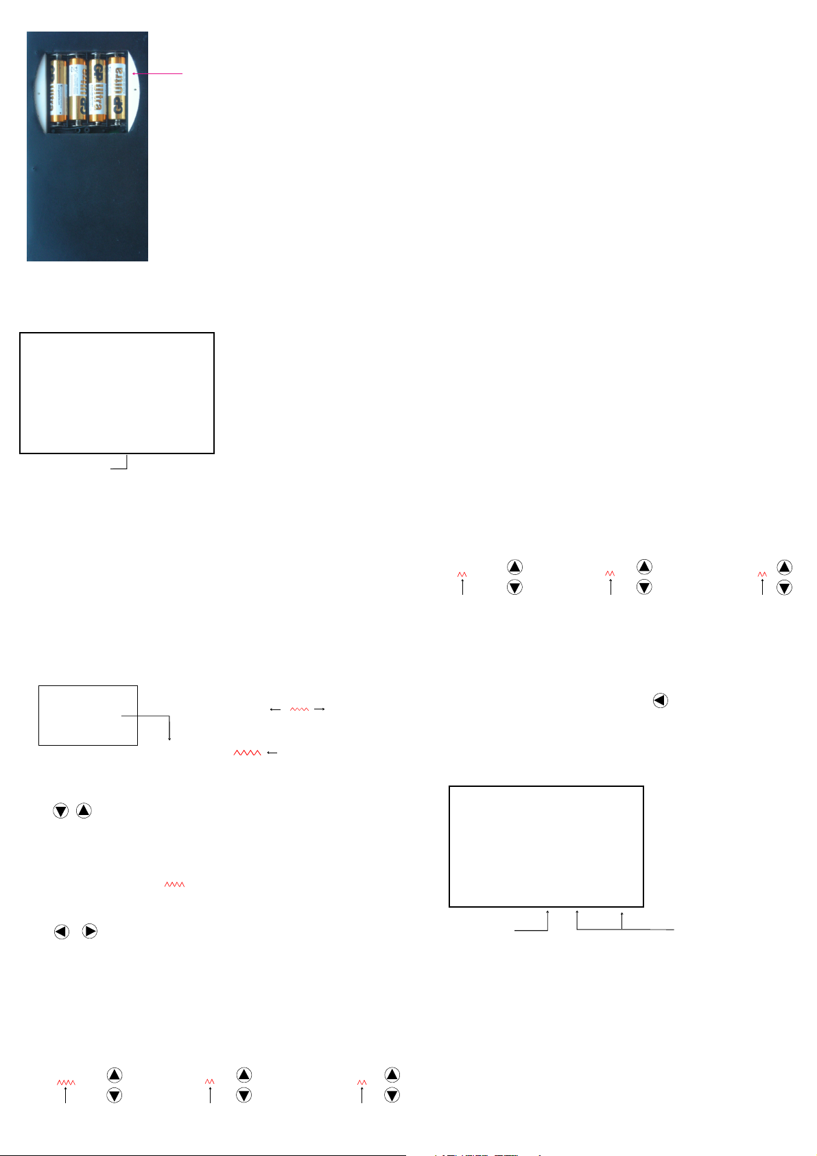
Fitting Batteries
-
-
+
+
Only fit standard AA batteries in the VibWire-201-Pro.
AA 1.5 V Cells
-
+
-
+
Initial Start-up Screen
Frequency
99.00
Selected Sensor (1)
Frq
99.00
Dig
9.80
9.80
Val
Battery level
when a new set of
batteries are installed into the unit.
Hz
Res 1000000.00
Tem -70.2
Dg
SI
2016-01-20 08:40::17
2016-01-20 08:40:17
6 V
3003.56
24.89
Fig-10
Hz
Ohm
C
Fig-11
1. Remove the battery cover from the rear of the device by simply unscrewing the securing bolts.
2. Replace the battery set in the layout shown in the image opposite.
3. Replace the battery cover and power on the unit.
The battery level indicator will show 6V when a new set of batteries has been installed See Fig 11.
Battery Life
When operating as a single channel device using a new set of batteries the VibWire-201-Pro will operate for
approximately 40 Hours continuous use.
MUX-16/32 Expansion Operations
The VibWire-201-Pro powers the MUX-16/32 expansion unit directly across the SDI-12 BUS and will reduce the
battery life of the device if used without an external power supply.
IMPORTANT NOTE
Remove the batteries from the VibWire-201-Pro should the device not be used for a long period of time.
Low Battery Level Effects
Once the battery levels falls before 4.5 V then
1. Display may not update at the correct rate and appears to flicker.
2. Measurement values can be erratic.
Once the display falls below 4.5V then the ‘Low Battery’ indicator flashes, see Figure 13 below. Should the unit
continue to operate then the display may flicker. Fit a new set of batteries.
Setting the Real-time Clock
The real time clock in the VibWire-201-Pro is configured using the ‘Set Time
and Date’ menu. See Page FF section G.
The VibWire-201-Pro can be used as a stand-alone VW sensor data logger
recording measurements automatically, and also to take single shot readings
under ‘User’ control.
Measurements are stored to the flash memory card.
See Page MM for details on selecting the ‘Time and Date’ menu.
Real-Time Clock Menu System
Set Time and Date
Date 2016-01-06
Time 08:25:30
Fig-12
Example
6th January 2016
08:25 AM 30 Seconds
Use the Up and Down keys between ‘Date’ and ‘Time’ options.
Down Up
Select Date or Time to be configured
Use the ‘Menu-Out’ and ‘Menu-In’ keys to move along the Date or Time fields.
As the keys are pressed the item indicator symbol will be displayed
under chosen item.
Menu-InMenu-Out
Once the parameter to adjust has been chosen then use the ‘Up’ and ‘
buttons to make changes.
The ‘Up’ and ‘
Down
’ buttons will increment, or decrement a parameter by 1 unit
after each action.
(Time/Date For mat)
Date Year-Month-Day
Time Hours:Minutes:S econds
(Selected Item Indicator)
Down
’
Adjusting the Time
Down
Up
Time 09 : 23: 06
Secs
Time 09 : 23: 06
Hours
Down
Up
Time 09 : 23: 06
Mins
Move through each date an and time parameter in turn making adjusts as
necessary.
Saving New Parameters
Once all parameters have been set, press the button unit the
Menu-Out
default ‘Frequency’ menu is displayed.
The new date and time values will be stored and the real-time clock settings
updated to the different menus.
Frequency
Hz
99.00
Selected Sensor (1) EDV-30
Frq
99.00
Dig
9.80
9.80
Val
Low Battery
Indicator
Note
The VW201cal.exe Windows configuration software automatically sets the
time and date used by the VibWire-201-Pro to the PC clock.
Hz
Res 1000000.12
Tem -70.2
Dg
SI
Low Battery
24.89
Ohm
C
3003.56
2016-01-21 10:40::17
2016-01-20 08:40:17
Fig-13
Date and time string will update
with the new settings.
Up
Down
Adjusting the Date
Date 2016-01-06
Year
Down
Up
Date 2016-01-06
Month
Up
Down
Date 2016-01-06
Day
Up
Down
VibWire-201-Pro User Manual 8
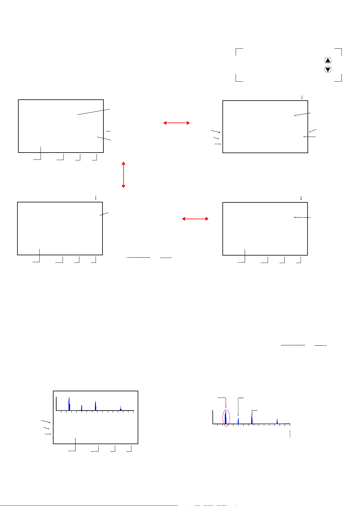
Real-time Results
Figures 14 below shows the default display that appears as soon as the device is powered on and with no sensor connected to an input port.
Upon connection of a sensor to the input port then the device automatically displays the frequency and temperature values.
With no sensor coil connected to the frequency input then the device defaults to 99.00 Hz.
Initial Start-up Screen
Frequency
99.00
Selected Sensor (4) EPP-30V
Frq
Dig
Val
SI Units
See Note 1
99.00
9.80
9.80
Battery
Voltage
Hz
Dg
SI
Res
100000.1
Tem
2016-01-20 08:40:17
6 V
Date Time
-70.20
Fig 14
Hz
Ohm
C
Fundamental Frequency
Resistance Thermistor
temperature sensor built
into a VW sensor.
Instant sensor
temperature in Deg C
Frequency Results - Hz
Frequency (Hz)
Digits - Hz2/1000
Engineering Units
Once a vibrating sensor is connected to an input port the display will change
similar to that shown above.
Frequency Results - Hz2 (Digits)
Fig-16
Digits
VW Sensor - SI Unit (Dig its)
D
Natural Units (SI)
Fundamental Frequency
2534.86
Selected Sensor (4) EPP-30V
Frq
2534.86
Dig
6424.95
992.28
Val
SI Units
Battery
Voltage
Hz
Dg
SI
Res
3003.56
Tem
2016-01-20 08:40::17
6 V
Date Time
24.89
Ohm
C
in Digits
All Keynes Controls VW sensor
instrumentations uses the digits
calculation
Digits = Frequency 2
1000
(Hz2)
1000
Use the ‘Up’ and ‘Down’ arrow keys
to switch between the different
results screens.
Fig-15
Frequency
834.69
Selected Sensor (4) EPP-30V
Frq
834.69
Dig
696.70
696.70
Val
Fig-17
Sensor
300.31
Selected Sensor (4) EPP-30V
Frq
876.86
768.36
Dig
300.31
Val
SI Units
Battery
Voltage
Important Note
Hz
Res
Tem
Dg
SI
6 V
Hz
Res
Tem
Dg
SI
5.2 V
Date Time
VW Sensor - SI Unit (Hz)
3571.73
2016-01-20 08:40:17
Ohm
C
21.07
VW Sensor - SI Unit
Nat Units
18.67
Ohm
C
3984.29
2016-01-20 08:40::17
Hz
Sensor Frequency (Hz)
Output value in
engineering
units.
Up
Down
Thermistor
Resistance Value
VW sensor
Temperature Deg C
The VibWire-201-Pro undertakes the spectral calculations on the incoming
vibrating sensor signal and gives the results immediately.
There are no ‘User’ configuration settings required to be assigned in order to
undertake a spectral calculation.
The largest peak is taken as the fundamental operating frequency of the sensor.
See Fig 19 opposite.
Spectra (Hz)
Frequency (Hz)
Digits - Hz2/1000
Engineering Units
VW Spectra Screen
FFT Sensor Spectra
992.28
6 10 11
Hz
Dg
SI
Battery
Voltage
0 1 2 3 4 5
Selected Sensor
Frq
2534.86
6424.95
Dig
Val
SI Units
7
KHz
Res
Tem
6 V
3003.56
2016-01-20 08:40::17
Date Time
12
24.89
Fig-18
131415
Ohm
C
Once the calibration factors have been set, and the process option set to ‘2’ see
Fig 24 on page 11.
All Keynes Controls VW sensor instrumentations uses the digits calculation
FFT Sensor Spectra
Fundamental
Frequency
0 1 2 3 4 5
2534.86
= Fundamental Frequency in Hz
6424.95
= Fundamental Frequency in Digits
st
1
Harmonic
Frequency
nd
2
Frequency
6 10 11
7
KHz
Digits = Frequency 2
1000
Harmonic
12
15
13
14
Maximum Operating
Frequency
(Hz2)
1000
Fig-19
Note. The example screens have been determined using a free standing
Encardo-Rite EPP-30V pressu re sensor
Copyright Keynes Controls Ltd 2015
VibWire-201-Pro User Manual 9
Selecting Remote Network Connections
The VibWire-201-Pro unit can connect to the SDI-12 and RS-485 networks for use in remote vibrating wire sensor measurements.
The SDI-12 and RS-485 ports enable the VivbWire-201-Pro to transmit sensor data into third party data logger and acquisition systems.
Device Port Selection
To select the network port type for remote data acquisition operations on the VibWire-201-Pro, use the menu system to select either of the menu items shown
below.
The device will then make measurements, and transmit data over the specified network port.
Page 30 shows the menu system built into the VibWire-201-Pro.
SDI-12 Port Operation
Frequency
2534.86
Selected Sen sor
Frq
Hz
Res
2534.86
Dig
Dg
Tem
6424.95
992.28
Val
SI
6
RS485
Port Opera
Frequency
2534.86
Selected Sen sor
Frq
Hz
Res
2534.86
Tem
Dig
Dg
6424.95
992.28
Val
SI
6
3003.56
24.89
2016-01-20 08:40::17
3003.56
24.89
2016-01-20 08:40::17
Menu-In
Hz
Ohm
C
tio
n
Hz
Ohm
C
Menu-In
Sensor No
Logger
Multiplexer
Remote
System
Sensor No
Logger
Multiplexer
Remote
System
Main Menu
Main Menu
Menu-In
Menu-In
Remote
Address
Serial Comms
Remote
Address
Serial Comms
Menu-In
Menu-In
SDI12
RS485 1200
SDI12
RS485 1200
Select Backlight
Select Backlight
Fig-20
Sets the VibWire-201-Pro to transmit data
through the SDI-12 Port
Sets the VibWire-201-Pro to transmit data
through the RS-485 Port
Fig-21
For single channel operation, once the output port is specified the sample data can be shown on the display.
SDI12 Remote Port
Remote Mode
Port = SDI-12
Address = 1
Measurement Count = 1 032
Selected Sensor
Hz
2534.86
6424.95
992.28
Dg
SI
Res
Tem
2016-01-20 08:40::17
6
Frq
Dig
Val
D
Ohm
3003.56
C
24.89
Number of measurements since
start of measurements on a
network. ID = 1.
RS485 Remote Port
Remote Mode
Port = RS485
Address = 3
Measurement Count = 1 53
Selected Sensor
Hz
Res
2534.86
Frq
Dig
6424.95
992.28
Val
3003.56
Tem
Dg
SI
2016-01-20 08:40::17
6
Number of measurements since
start of measurements on a
network. ID = 3.
24.89
Ohm
C
D
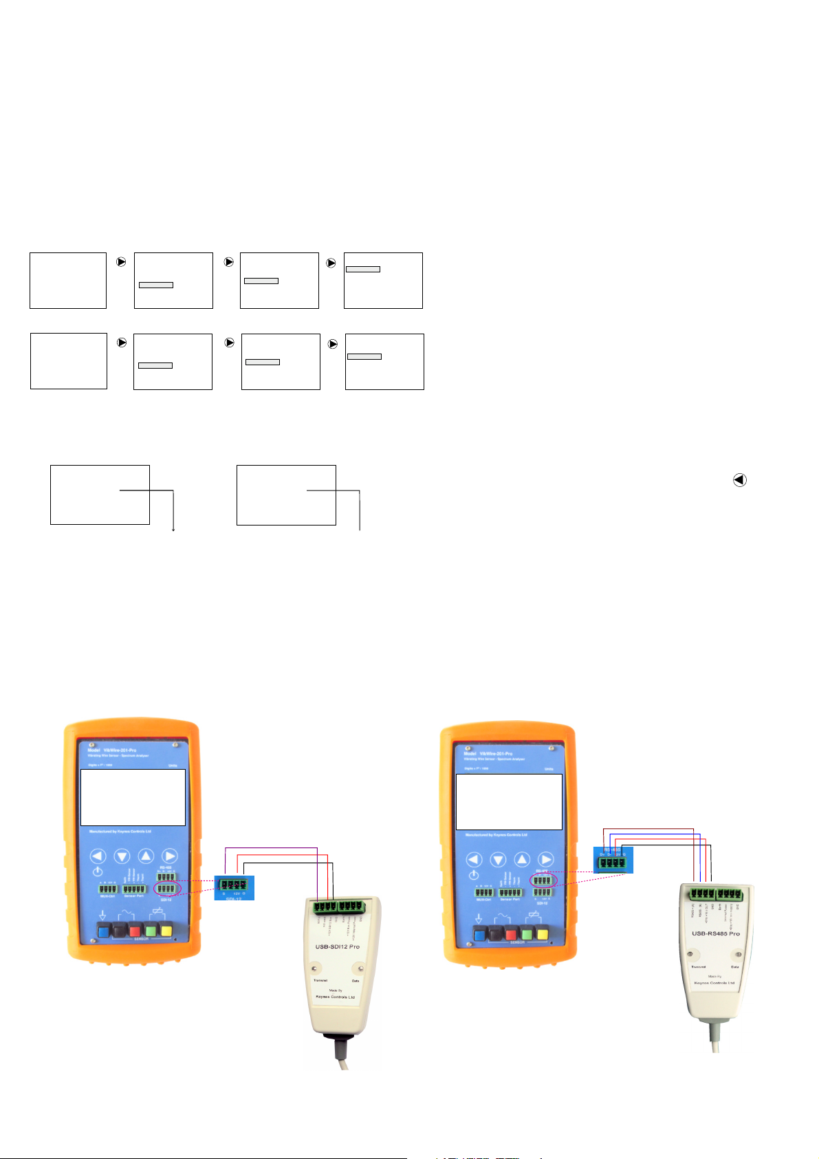
SDI-12 Network Connection
Figure 22 below shows how to connect the VibWire-201-Pro SDI-12 port to a
USB-SDI12-Pro media converter. The USB-SDI12-Pro media converter connects to a Windows PC and allows measurements from VibWire-201-Pro to
displayed directly into
Storing the menu option
Once the selected menu option is highlighted simple press the button
to store the new option.
Repeat the operation until the ‘
page 8.
RS-485 Network Connection
Figure 23 below shows how to connect the VibWire-201-Pro RS-485 port to a
USB-485-Pro media converter. The USB-485-Pro media converter connects to
a Windows PC and allows measurements from VibWire-201-Pro to displayed
directly into the Q-LOG data display and recording software.
The VibWire-201-Pro acts like any other intelligent 485 device, and will operate
with any other suitable device 3rd party device on the network.
Frequency
Menu-Out
’ display appears. See Figure 15 on
Remote Mode
Port = SDI-12
Address = 1
Measurement Count = 1032
Selected Sensor
2534.86
Frq
Dig
6424.95
992.28
Val
VibWire-201-Pro
Hz
Dg
SI
Res
Tem
2016-01-20 08:40::17
6
3003.56
24.89
Fig-22
D
Ohm
C
SDI-12 Data
SDI-12
Port
Part No: USB-SDI12-Pro
12 DC
Fig-23
Res
Tem
2016-01-20 08:40::17
6
3003.56
24.89
Ohm
C
D
+ RS-485
- RS-485
12 DC
Gnd/0V
Remote Mode
Port = RS485
Address = 3
Measurement Count = 153
Selected Sensor
Hz
2534.86
Frq
Dg
6424.95
Dig
992.28
SI
Val
Gnd/0V
Part No. USB-485-Pro

VibWire-201-Pro User Manual 10
Technical Specification
The current technical specification for the VibWire-201-Pro is:
Description
Physical Size
Weight
Battery
Auto-logging no back light
Communication Ports 1 x RS-485 Slave - 1200 Baud, 8 data, 1 stop, no parity
External Power Supply 10 - 15V DC @ 100 mA min specification
Vibrating Wire Measurements
Analogue Input 24 Bit Sigma Delta
Sensor Excitation Auto-resonance - Fully automatic
Operating Frequency 400 - 15 KHz
Measurement Resolution 0.001 Hz RMS - 20 to 70 Deg C
Measurement Accuracy ± 0.014% of reading - 20 to 70 Deg C
Spectral Analysis
Resolution
Window Function
Update Rate 0.25 Sec typical
SI Units Hz, Digits (Hz2/1000), Eng Units
Temperature Measurements
Analogue Input 24 Bit Sigma Delta
Measurement Range - 50 to 100 Deg C
Measurement Accuracy ± 0.25 % of reading - 20 to 70 Deg C
SI Units Deg C
Cal Factors Steinhart-Hart
Bridge Type Half Bridge
Expansion Options
1 x MUX-16/32 expansion unit
Scan rate 2 Sec/Chan - using expansion module
Memory Expansion 1 x SD Card = 1 .. 32 GB
(Excluding boot cover)
Height 184 mm - Width 74 mm - Depth 32 mm
125 g
4 x AA - 2000 mA/Hr
6 mA - standby - 340 Hours continuous use
20 mA/Hr with display - Low
50 mA/Hr with display mode - Full brightness
150 mA/Hr with MUX-16/32 - Peak (Note-1)
1 x SDI-12 - - 1200 Baud, 8 data, 1 stop, no parity
1 x micro USB configuration port
Differential Coil (V+) and Coil(V-) for direct connection of
sensor, excitation and resonant frequency measurement.
Digital signal processing for excellent noise rejection,
1024 line Zoom FFT - with data weighting
0.001 Hz
Hamming
(Quadratic Cal Factors)
Used for temperature compensated vibrating wire
measurements, and stand-alone temperature sensors for
Geotechnical applications. Ratio-metric measurement.
Beta Value - lower performance using Beta
1..32 - 2 Wire Freq inputs
1..32 - Temp (thermistor) inputs
1..16 - 4 Wire vibrating wire sensor inputs
250 ms update to screen
Temperature Measurements
The VibWire-201-Pro is factory set to use the most common thermistor
calibration factors that is fitted into most manufactures vibrating wire sensors.
The thermistor is used to measure temperature.
The thermistor calibration factors are taken from the sensor material
manufactures data sheet and are as accurate as possible.
The voltage input measurements are factory calibrated to traceable national
standards, and can be externally calibrated upon request. There is an extra
charge for operation.
Common VW Sensor Thermistor Part Numbers
YSI 44005
Vishay 1C 3001 B3
RS Part no: 151-215
The part numbers are for 3 K Ohm thermistor commonly used by most
different VW sensor manufacturers to measure temperature
The sensors give 3 K Ohm resistance at 25 Deg C
The most common material used in these sensors uses material type F
from GE sensing.
Under most practical applications, the in-built thermistor calibration factors will
give accurate results without the User having to be concerned with
understanding of process involved.
Simply connect the thermistor output from the sensor to the VibWire-201-Pro
and the device will instantly display the temperature.
Sources of Error
The principle source of error in field measurements will the added resistance
due to long sensor wires. The resistance added to the thermistor measurement
will give a fixed offset error. Make temperature measurements as close to the
temperature sensor as is practically possible.
Calibration Factor Error
Take care when using the calibration factors supplied on a vibrating wire sensor
manufactures data sheet. The factors are often given from sample sensors taken
from a batch and not necessarily from the individual sensor being used. Where
possible ensure that the sensor manufacturer calibrates the sensor and supplies
all test data so that the calibration factors can be verified.
Storage file format CSV - Comma Separated Variables
Logging Rates
16 x 4 Wire Mode
32 x 2 Wire
No. Pre-set Sensor Configurations
File Type Format DOS
Operating Temp Range -20 to 75 Deg C
Storage temperature >5 Deg C with batteries installed.
Note-1 - Use external supply for long term monitoring with MUX-16/32 unit
150 mA peak .
Internal to flash card
1s, 10s, 1 Min, 10 Min, 1 Hour, 6 Hours
MUX-16/32 Expansion
30 Sec/Chan
1 minutes
10 user defined sensors options
Associated Part Numbers
Part No:
VibWire-201-Pro - FFT VW Sensor Interface
USB-485-Pro - Isolated USB to 485 media converter
USB-SDI12-Pro - Isolated USB to SDI12 media converter
MUX-16/32 16 x 4 Wire/ 32 x 2 Wire Expansion unit
Device Configuration Software
The VibWire-101-Pro configuration software runs with on most modern
Windows platforms such as XP, 8.1 and 10 operating systems.
Table 1
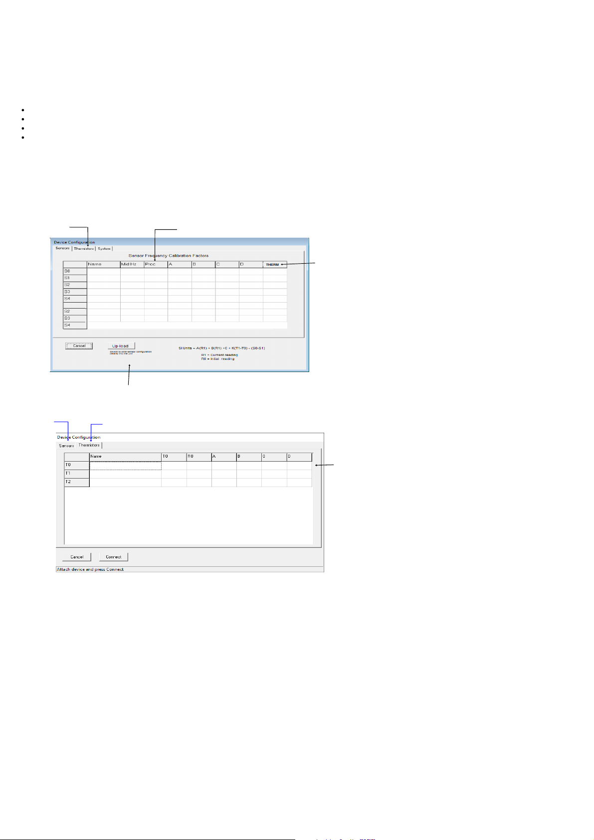
User Defined Stein-hart-Hart Calibration Factors
The VibWire-201-Pro has the facility to enter User defined Steinhart-Hart
calibration factors.
The calibration factors are entered into the device using the VW201cal software
package. See figure 57 on Page 20.
Sensor Information
A calibration report should be provided with each vibrating wire sensor and it will
contain all the information required to convert Hertz, the frequency value output
by the sensor into appropriate SI units (e.g., displacement, pressure etc..)
1. If the values in the Calibration Report are in digits, use the following equation
to convert the VibWire-201-Pro frequency values from Hertz to digits.
Digits = Frequency 2
1000
(Hz2)
1000
2. Use the gauge factors and polynomial provided in the Calibration Report to
calculate SI units.
The VibWire-201-Pro uses:
Natural Units = A(R1)2 + B(R1) + C + K(T1-T0) - (S1-S0)
(Equ 1)
Calibration equation.
The software automatically identifies the USB port in use and allows for a true
plug and play operation. Simply enter the sensor calibration factors and select
the ‘Connect’ button to store parameters into the device.
Download the software at:
and this is expanded to:
= C(R1-R0)2 + B(R1-R0) + A + K(T1-T0) - (S1-S0)
(Equ 2)
when initial conditions in the measurements are involved.
The additional terms used in equation 2 only change the constant parameter
( A ) when used.
VibWire-201-Pro User Manual 11
Pre-set Sensor Configurations
The VibWire-201-Pro cab be configured using the
http://www.aquabat.net/downloads/
VW201cal.zip
VW201cal.exe
software which is available as a free download at:
Features
The VW201cal software gives the User the ability to configure the VibWire-201-Pro in an easy to use Windows environment.
Automatically sets time and date to host PC.
Set the User defined frequency and temperature calibration factors.
Select preset thermistor calibration factors.
20 Pre-set sensor configuration options.
The sensor names entered into the VW201cal software appear on the VibWire-201-Pro sensor list.
The VibWire-101-Pro supports up to 20 built-in User defined vibrating wire sensor configuration options.
Sensor Configuration
Thermistor
Calibration
Factors
EPP-30V
5200 2
SI Unit = A + B(R1)+ C(R1)2 + D(T)
Process Option
0 = Frequency,1 = Digits, 2 = SI Un its
-1720.23
-2159.487
2.8388E-1
3.1728
2
-0.0870
T0
where R1 = Current Reading
T = Temp Deg C
D = Thermal Factor
Thermistor Type T0, T1, T2 ….. etc
Figure 24 opposite shows the VibWire-201-pro Setup software used for entering the calibration
factors for a Vibrating wire sensor.
This Window is used to enter the frequency component calibration factors. The calibration factors
are used to enable the VibWire-201-Pro to display measurements directly in engineering SI units.
Write configuration details
into the device.
VW sensor
calibration factors
Select Therm istor Calibrat ion Window
Default-Therm
300025
Fig 25 Default Thermistor Calibration Factors
Downloading and Installing device setup software
1.
Download the VW201cal software from:
http://www.aquabat.net/downloads/VW201cal.zip
Run the install software script.
3.35E-3
2.56E-4
2.08E-6
Fig 24
7.30E-8
Default Steinhart-Hart
calibration factors
Figure 25 opposite shows the thermistor calibration settings window for the
The factory set default thermistor parameters for T0 are displayed.
SI Units
In order for the SI unit formulae be applied the process option has to be set to
‘2’. Fig 24 above shows how this is done.
Setting the process option to 0 or 1 shows results in Hz or Digits.
VW201cal
software.
Follow the on-line instructions to install and activate the software.
Once activated the main Window shown in Fig 24 above will be displayed.
Automatically setting the Real-time Clock
The VibWire-201-Pro can be used as a stand-alone VW sensor data logger
recording measurements automatically, and also to take single shot readings
under ‘User’ control. In order to act as a logger the internal real-time clock has
to be set.
The real-time clock is used to keep track of the time and date of a measurement.
The clock is set automatically the VibWire-201-Pro is connected to the PC via
the USB cable and the ‘
Upload’
button is activated. Once the sensor data is
written into the device then the clock is automatically synced to the host PC.
Common VW Sensor Thermistor Part Numbers
The part numbers are for 3 K Ohm thermistor commonly used by most
different VW sensor manufacturers to measure temperature
The sensors give 3 K Ohm resistance at 25 Deg C
The most common material used in these sensors uses material type F
from GE sensing.
YSI 44005
Vishay 1C 3001 B3
RS Part no: 151-215
Pre-defined Thermistor Calibration Parameters
The VibWire-201-Pro uses the following predefined calibration parameters to
defining the operation of the 3 K Ohm thermistor temperature sensors built into
most Vibrating Wire sensors.
(Steinhart-Hart Factors)
A = 3.35E-3, B = 2.56E-4, C = 2.08E-6, D = 7.30E-8
VibWire-201-Pro User Manual 12
Channel Expansion Options
The VibWire-201-Pro is expanded using a single MUX-16/32 expansion unit.
The expansion unit offers 16 x 4 wire or 32 x 2 wire sensor operations.
16 x 4 wire mode offers 16 x Frequency and 16 x Temperature inputs.
The 32 x 2 Wire sensor mode offers 32 x Frequency inputs or 32 x temperature measurements.
The VibWire-201-Pro can record data internally onto a SD memory card, or remotely across a digital network to a stand-alone PC running the Keynes Controls
Q-LOG applications software.
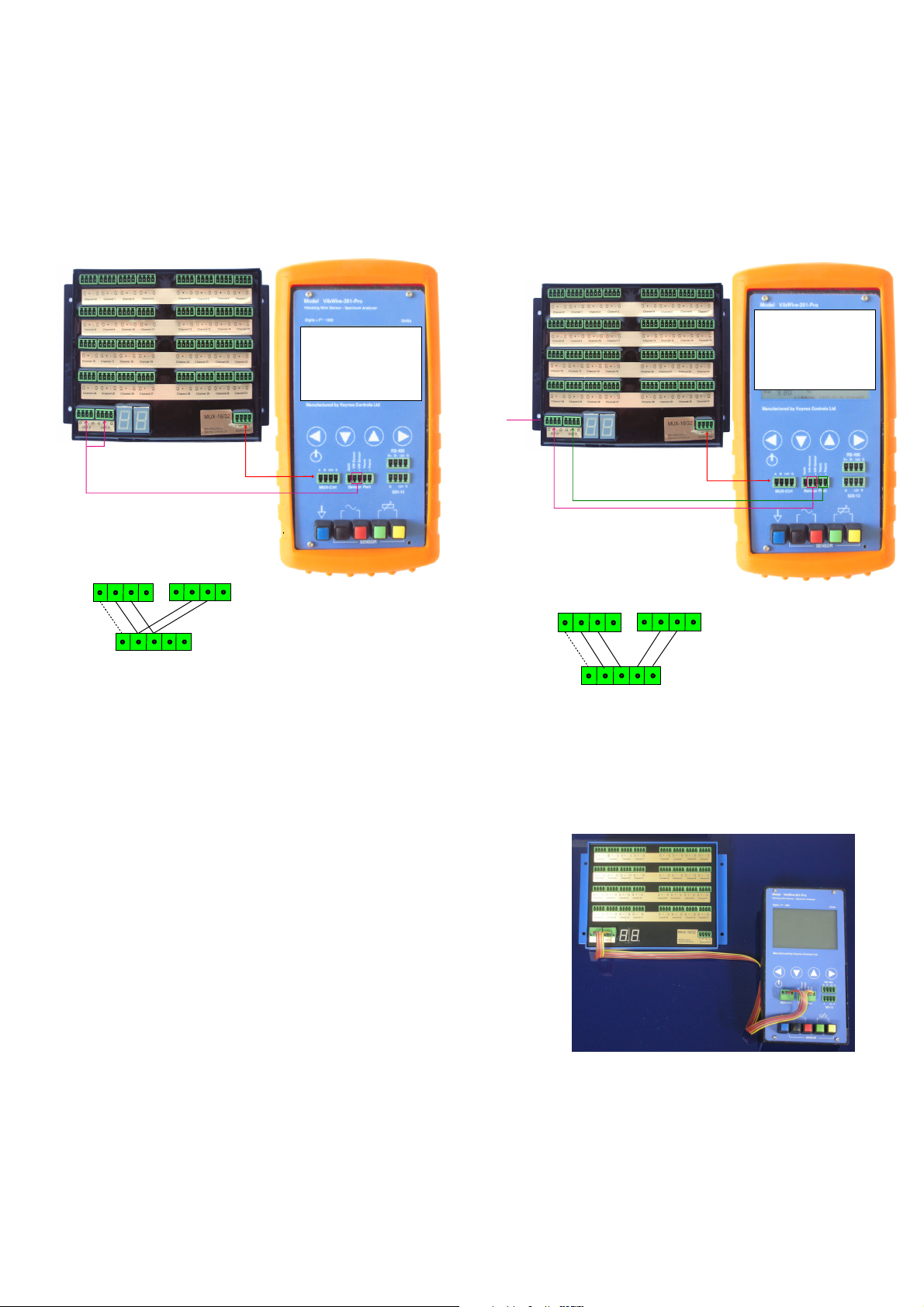
32 x 2 Wire Expansion
Output Ports on
the MUX-16/32 Unit
-
+
Out-0 Port
(MUX-16/32)
- VW Sense
+ VW Sense
- Therm
-
+
Sensor Port
+ Therm
(VW-201-Pro)
Unit shown below is configured for 32 x 2 wire
frequency measurements.
Sequencing MUX
MUX 0
21
Selected Sensor
Frq
Hz
Res
Ohm
3003.56
C
24.89
Tem
Out-1 Port
(MUX-16/32)
2534.86
Dig
Dg
6424.95
992.28
Val
SI
Fig-26
16 x 4 Wire Expansion
4 Wire operations records frequency and temperature simultaneously.
Sequencing MUX
MUX 1
12
Selected Sensor
Frq
Hz
Res
3003.56
24.89
Tem
Dg
SI
MUX-16/32
Output Ports
Out-0 Port
(MUX-16/32)
Output Ports on
the MUX-16/32 Unit
-
+
- VW Sense
+ VW Sense
- Therm
-
+
Sensor Port
+ Therm
(VW-201-Pro)
Dig
Val
Out-1 Port
(MUX-16/32)
2534.86
6424.95
992.28
Ohm
C
Fig-27
2 Wire operations records frequency or temperature but not both at the same
time.
MUX-16/32 Expansion Unit - User manual
For 32 x 2 wire operations the output ports on the MUX-16/32 expansion unit are connected together.
Full details for configuring and the MUX-16/32 unit can be seen in the User manual.
Download the User manual at
http://www.aquabat.net/downloads/mux32manualv1.pdf

VibWire-201-Pro User Manual 13
Number of Channels
The VibWire-201-Pro data supports 4 data recording modes:
Single Channel
- Records measurements from the sensor attached directly to the instrument.
The following modes require the MUX-1632 expansion unit to be fitted:
MUX-16/32 Expansion Unit
16 x 4 Wire (VW and Temp)
32 x 2 (VW only)
32 x 2 (Freq)
- 32 x Freq
- 32 x Temp
- 16 x Freq + 16 x Temp
when using the MUX-16/32 expansion unit 32 measurement values are stored into each record.
To select the data recording mode
1. Make sure a flash memory card is installed into the VibWire-201-Pro, See Page 5 Figure 2.
2. Starting at the default ‘Frequency’ display, use the ‘
The
Mux Mode
3. Use the ‘Up’ and ‘
menu system will appear.
Down
’ keys to select the mode of operation of the instrument.
Menu In
’ key to select ‘
System Setup
’ followed by ‘
Setting Scan Mode
Frequency
2534.86
Selected Sensor
Frq
Dig
Val
2534.86
6424.95
992.28
Hz
Dg
SI
Res
3003.56
Tem
2016-01-20 08:40::17
6
24.89
Ohm
C
Menu-In
Hz
Up
Down
Main Menu
Sensor No
Logger
Multiplexer
Remote
System
Use the ‘Up’ and ‘
to select the ‘Logger’ option.
Down’ keys
Menu-In
Up
Down
System Setup
Log Now
Autolog Mode
Scanning mode
Recording Interval
Set working MUX ID
Use the ‘Up’ and ‘Down’ keys
to select the ‘Scanning mode
option.
’
Menu-In
Mux Mode
Selected Scanning mode
Single Chan
16x4 (VW and Temp)
32x2 (VW only )
32x2 (Temp only )
’ menu options.
Fig-28
Menu system define s the number of
measurements made after each scan. The
MUX-1632 expansion unit must fitted for 16x
4 wire or 32 x 2 wire operations.
Data Recording
The VibWire-201-Pro can store measurements directly on to a SD flash memory card.
Max SD Card = 32 Gb (160 million records)
DOS format file system.
The data table stores results in C.S.V. (Comma separated variable), for direct importing into spreadsheet such as Microsoft Excel.
Data Recording Options
The VibWire-201-Pro supports 3 x logging modes. Single Channel, 16 x 4 Wire and 32 x 2 Wire.
Single Channel
Both the 16 x 4 Wire and 32 x 2 wire recording modes require the use of the MUX-16/32 expansion unit.
16 x 4 Wire
16 x Frequency + 16 x temperature.
32 x 2 Wire -
- Continually records a single measurement from a sensor connected to the sensor port on the device.
1 x single measurement on demand.
Single Channel on MUX-16/32 Unit.
- 32 measurement values made up of
Important Note
The VibWire-2-1-Pro will adjust automatically to the fastest sample rate
32 x Frequency measurements.
allowed for the number of channels to be scanned.
The fastest sample rate that is allowed for a 32 channel operation
operation is 60 seconds (1 min).
Set Logging Interval
Frequency
2534.86
Selected Sensor
Frq
Dig
Val
Fig-29
2534.86
6424.95
992.28
Hz
Dg
SI
Res
3003.56
Tem
2016-01-20 08:40::17
6
24.89
Hz
Ohm
C
Menu-In
Up
Down
Main Menu
Sensor No
Logger
Multiplexer
Remote
System
Use the ‘Up’ and ‘Down’ keys to
select the ‘Logger’ option.
Menu-In
Up
Down
Logger
Log Now
Autolog Mode
Scanning mode
Recording Interval
Set working MUX ID
Use the ‘Up’ and ‘Down’ keys to
select the ‘Recording Interval’
option.
Menu-In
Down
Select Recording Interval
1 Second
10 Second
1 Minute
10 Minute
1 Hour
6 Hour
Up
1 Second - only for single chann el operations
10 Second

VibWire-201-Pro User Manual 14
17 Commands for scanning MUX-16/32 in 32 x 2 wire mode
Table 2 below shows the commands used to scan the MUX-16/32 unit in 32 x 2 wire mode.
The MUX-16/32 unit has to be set to operate in 32 x 2 Wire mode. This is done via the VibWire-101 setup menu.
See page 17, section 25.2 for instruction in setting the ‘Scan Mode’.
In 32 x 2 wire mode the channel counter displays the range 0 .. 31.
Start Measurement
Command
aM2!
aM3!
Description Channel
MUX ID=0 Chan 0..15 Chan 0 .. 15 Returns 16 values x Freq aD0! aD1! aD2! aD3!
MUX ID=0 Chan 16..31 Chan 16 .. 31 Returns 16 values x Freq aD0! aD1! aD2! aD3!
Number
No. Data Values SDI-12 Get Data Command
Channel Select Display - Fig 30
to
Table 2
Chan 0..15 Freq
Fig 31 - Output Ports used in 2 Wire mode.
32 x 2 Wire mode
Each get data command
returns 4 values.
Chan 16..31 Freq
When operating in 2 wire mode, the VibWire-101 scans the MUX-16/32 in blocks of 16 channels.
Under normal operating conditions Channels 0-15 are scanned first and the results stored into a data table. This is followed by
the scanning the final block of 16 channels and storing the measurements. Table 1 shows the sequence of the 2 blocks of
commands needed to scan the MUX-16/32 unit in 2 wire mode.
16 Switching between 2 & 4 Wire Mode Operation under SDI-12 Command
The MUX-16/32 expansion unit supports 2 and 4 wire VW sensor operations. The selection between 2 and 4 wire sensors is
undertaken using software commands only and these are issued across the MUX-16/32 using the SDI-12 control port. The same
procedure for issuing instructions for changing the ID number is followed as is used for selection the mode of operation.
The following SDI-12 command selects 2 or 4 wire sensor operation:
aXDn! (n=0 or 1) Sets 2 or 4 wire operations on the MUX-16/32.
to
Channel Select Display - Fig 31
16 x 4 Wire mode
Example SDI-12 command ‘ 0XD1!‘ sets MUX-342 with ID=0 to 4 Wire mode.
18 Commands for scanning MUX-16/32 in 16 x 4 wire mode
Table 2 below shows the commands used to scan the MUX-16/32 unit in 16 x 4 wire mode.
The MUX-16/32 unit has to be set to operate in 16 x 4 Wire mode. This is done via the VibWire-101 setup menu.
See page 17, section 25.2 of the User Manual for instructions in setting the ‘Scan Mode’.
In 16 x 4 wire mode the channel counter displays the range 0 .. 15.
Fig 32 - Sensor Output Ports
Start Measurement
Command
aM2!
Identification
MUX-0
Chan 0..15
MUX
Channel
Number
Chan 0 ..15 returns 32 values
No. Data Values SDI-12 Get Data Command
16 x Freq + 16 x Temp
aD0! aD1! aD2! aD3! aD4! aD5! aD6! aD7!
Table 3
To VW frequency
port on the VW101
To temperature
port on the VW101
After each MUX has been scanned, and all 32 sensor readings have been taken, then the following command is required
to download the data from the VibWire-101 to a data table in the AquaLOG data logger. The same command should work on
any suitable SDI-12 data logger.
Get data:
aD0! aD1! aD2! aD3! aD4! aD5! aD6! aD7!
16 x Freq Readings
16 x Temperature Readings
where each command aD0! returns 4 values

VibWire-201-Pro User Manual 15
IMPOR
The MUX
VibWire-2
Full deta
found in
http://ww
The MUX
is assign
SDI-12
TANT NOTE
-16/32 expansion
01-Pro for addition
i
ls for sensor conne
t
he User manual at
w.aquabat.net/dow
-16/32 unit operati
e
d using the Q-LOG
C
ontrol Port
16 x 4 Wire Expansion
Frequently Asked Questions
1.
u
nit is used to expa
n
d the
al channel.
c
tion and operation
can be
:
nloads/mux32m
n
g mode, 16x4 wire
software via the in-
a
nualv1.pd
or 32x2 wir
built
.
What cable is used to connect the VibWire-201-Pro to a data logger.
A single 4 core ribbon cable is all that is required for the most common SDI-12 and RS-485. No
special cabling is required for this instrument.
Figure 61 on page 21 shows the connections to a logger
f
Farnell Web Site:
e
Farnell Part No.
Manufactures Part No.
2.
What might cause an VibWire-201-Pro to not communicate with a data logger?
http::/www.farnell.co.uk
150427
05091504-01-50M
.
The maximum cable core diameter is 2 mm for
the sensor terminated with a plug for
connection to standard sensor input.
The sensor terminal posts can take larger
diameter cables.
There is no programming required for setting up and using the VibWire-201-Pro.
Sequencing MUX
MUX 1
12
Selected Sen sor
Frq
Hz
Res
3003.56
2534.86
24.89
Tem
Dig
Dg
6424.95
992.28
Val
SI
MUX-16/32
Output Ports
Output Ports on
the MUX-16/32 Unit
Out-0 Port
(MUX-16/32)
-
+
-VW Sensor
Earth
+VW Sensor
- Therm
+ Therm
-
+
Out-1 Port
Sensor Port
(VW-201-Pro)
(MUX-16/32)
32 x 2 Wire Expansion - Frequency Measurements
Sequencing MUX
MUX 1
20
Selected Sensor
Frq
Hz
Res
3003.56
2534.86
6424.95
24.89
Dg
Tem
992.28
SI
MUX-16/32
Output Ports
Dig
Val
Ohm
C
Fig 33
Ohm
C
The most common cause for lack of communication is faulty wiring. Check that the cable cores
are correctly terminated by into the plugs. Use a DVM to test each core and pin on the plugs
for continuity.
Make sure the correct network port is selected.
For SDI-12 communications see menu system in Figure 21 on Page 9,.
For RS-485 option - see menu system on Figure 22 on page 9.
Network ID number
Make sure the ID number used to identify the VibWire-201-Pro on a network is set correctly.
See menu system on page 29 section ‘
Setting network address’
, or by the standard SDI-12
commands on page 20. A full list of User commands is shown on page 19.
The ID number for the measurement command used to acquire data from the VibWire-201-Pro
must mach the ID number set in the device.
Logger using command: 3M! 3D0! - then the ID number should be set to ‘3’.
3003.56
24.89
2016-01-20 08:40::17
D
Ohm
C
Page 30 shows the menu options to set the ID number.
IMPORTANT NOTE
Remote Mode
Port = SDI12
Address = 3
Measurement count = 4312
Selected Sensor
Frq
Dig
Val
2534.86
6424.95
992.28
Hz
Res
Tem
Dg
SI
6
When multiple devices are being used on the same network, each device must have a unique
ID number assigned. Failure to do so will prevent the VibWire-201-Pro from communicating to
a logger unit.
Out-0 Port
(MUX-16/32)
Output Ports on
the MUX-16/32 Unit
-
+
Earth
+
Sensor Port
-VW Sensor
+VW Sensor
(VW-201-Pro)
-
Out-1 Port
(MUX-16/32)
Fig 34
32 x 2 Wire Expansion - Temperature Measurements
Sequencing MUX
MUX 1
20
Selected Sensor
Frq
Hz
Res
Ohm
3003.56
MUX-16/32
Output Ports
Out-0 Port
(MUX-16/32)
Output Ports on
the MUX-16/32 Unit
-
+
Earth
- Therm
+ Therm
+
Sensor Port
(VW-201-Pro)
-
Out-1 Port
(MUX-16/32)
99.00
Dig
9.90
9.90
Val
C
24.89
Dg
Tem
SI
Fig 35
How fast can the VibWire-201-Pro make a measurement?
Currently the fastest data recording rate is 1 measurement / Second for a single channel.
The fastest sample rate is supported on the SDI-12 and 485 network measurements using the
Q-LOG free data acquisition and display software, and to the in-built data recording to the flash
memory card.
Where Can I download a copy of Q-LOG software ?.
Download a copy of the Q-LOG software at:
http://www.aquabat.net/QLOGFree/qlogv2.html
Erratic Measurements - most common cause.
When the battery level goes below 3.9 Volts the measurements can be come noisy and erratic.
Replace the batteries in the unit for a new set, or connect an external power supply. Faulty
sensor coil seating which can be seen in the sensor results spectra.
How do make measurements on my PC without any programming experience.
Use the free Keynes Controls Q-LOG software which can downloaded without restriction from
the companies web site, and one of the USB-SDI12-Pro or USB-485-Pro media converters. The
Q-LOG Windows software can be configured
The Q-LOG software gives complete control of the data acquisition operations for the VibWire201-Pro in a simple to use Windows environment. See page 18 for additional information.
The USB-SDI12-Pro and USB-485-Pro media converters can both be power the VibWire-201-Pro
direct from a PC USB port. No additional power supply is required.
Install the software - Assign USB COM Port details - Scan Network ( Identify Instruments) - Start Data Acquisition.
The Log files are stored to C:/Q-LOG/Logfiles/’Timestamp-file’.TXT in a format suitable for reading
by a spread sheet package,
‘Timestamp-file.TXT
’ is a unique log file in CSV ( Comma Separated variable).

VibWire-201-Pro User Manual 16
Selecting a MUX-16/32 Channel
The VibWire-201-Pro can be used to manually select a channel on the
MUX-16/32 expansion unit and take readings.
The feature enables the user to test sensors during an installation, or to use the
MUX-16/32 expansion unit as a switch box. The channel selection works in 16
x 4 wire and 32 x 2 wire modes.
MUX-16/32 Settings for operation with VibWire-201-Pro
Signal and Control Ports
Fig-37
The MUX-16/32 must be set to
ID = 0
The setting of the MUX-16/32 ID number is easiest set using a USB-SDI12-Pro
media converter and Q-LOG software. See Page H Appendix A for details.
Out-1 Port
(VibWire-201-Pro)
D
0V
N/A
12V
D
Control Port
(MUX-16/32)
0V
N/A
12V
Wiring diagram for the MUX-16/32
control port to the VibWire-201-Pro
Fig 36
1. Connect the MUX-Ctrl port on the VibWire-201-Pro to the Control port on the
MUX-16/32 expansion unit.
Figures 33 to 35, page 15 above show the wiring diagram for the MUX control
ports.
MUX-16/32 User Manual
Full details for the operation and configuration of the expansion unit can be
found at:
http://www.aquabat.net/downloads/mux32manualv1.pdf
MUX Control Port
Sensor Output
Ports
FFT Sensor Spect ra
0 1 2 3 4 5
Selected Sens or
2534.86
Frq
6424.95
Dig
992.28
Val
6 10 11
7
KHz
Hz
Res
Dg
Tem
SI
6 V
12
131415
3003.56
24.89
2016-01-20 08:40::17
Mux-16/32
Channel Control
Port
Ohm
C
Fig-38
Manually setting the MUX-16/32 Channel
Manually set the MUX-16/32 channel number. The channel range will depend on the scan mode assigned.
The MUX Chan number indicator will change as the ‘Up’ and ‘Down’ keys are pressed.
Fig-39
Menu-In
3003.56
24.89
2016-01-20 08:4 0::17
Hz
Ohm
C
Frequency
2534.86
Selected Sensor
Frq
Dig
Val
MUX 0 .. 15 4 Wire Mode - MUX-16/32 Channel counter changes between 0 ..15
0 .. 31 2 Wire Mode - MUX-16/32 Channel counter changes between 0 ..31
2534.86
6424.95
992.28
Hz
Res
Tem
Dg
SI
6
Main Menu
Sensor No
Logger
Multiplexer
Remote
System
Main Menu
Off - Initial Position 0 - 15 (4 Wire) and 0 - 31 (2 Wire)
Channel Select Display
Menu-In
Actions Menu
Multiplexer
Manually set MUX
Set working MUX ID
The menu system above shows the commands to follow to manually adjust
the active MUX channel.
Menu-In
MUX Chan No.
MUX Chan No.
Channel
Counter
MUX-ID No
Use the ‘Up’ and ‘
The channel counter on the MUX-16/32 will update automatically.
Sequencing MUX
MUX 0
24
Selected Sensor
Frq
Dig
Val
Hz
Res
2534.86
6424.95
992.28
Down
’ buttons to change the MUX channel.
3003.56
24.89
Tem
Dg
SI
Ohm
C
Up
Down
Off - Initial setting
MUX-ID No
The image above shows the Initial Startup display
should the MUX channel selection be activated without
a MUX-16/32 expansion unit connected.
Sequencing MUX
MUX OFF
0
Selected Sensor
Frq
2534.86
Dig
6424.95
992.28
Val
Hz
Res
Tem
Dg
SI
3003.56
24.89
Ohm
C
Fig-40
to
to
16 x 4 Wire mode
32 x 2 Wire mode
Changing the MUX Channel Number
Use the ‘Up’ and ‘
Down
’ keys to manually select the MUX-16/32 channel.
As the keys are pressed the MUX-16/32 channel will increment.
The Channel counter on the menu system will increment/decrement at the
same time as the MUX-16/32 unit.

VibWire-201-Pro User Manual 17
Sensor Configuration Example - Piezometer
The following example shows how to configure the VibWire-201-Pro to use an Encardio-rite vibrating wire piezometer water level sensor. The piezometer is
configured in a similar way as to a strain gauge but has the added complication for requiring barometric correction for true water level measurements.
The example will use the linear formula to convert frequency to pressure into SI units of k Pa. (Kilo Pascal )
A copy of a sample calibration data sheet used in this example is shown in
Appendix-A
.
The example demonstrates how to allow for initial conditions to improve the accuracy of the measurements.
Temperature Compensated Calibration Factors - Results in Natural (SI) Units
The example below demonstrates how to use the calibration factors on a sensor data sheet, and local initial conditions to determine the factors to be used by the
VibWire-201-Pro to give results in SI Units. The example sensor data sheet, see Appendix-B page 32 gives results in kPa. Use suitable scaling factors to convert
the output into other SI Units. The formula section of Q-LOG can be used to convert pressure into other SI Units.
P(kPa) = G(R1-R0) + K(T1-T0) - (S1-S0)
where G = Linear gauge factor from the calibration data sheet.
= C(R1-R0)2 + B(R1-R0) + A + K(T1-T0) - (S1-S0)
where A B and C are the calibration factors used in the VW201pro software.
— Sensor formula for conversion frequency (in Digits) to kPa
— Formula used by VW201pro software for configuration
For this example there is no C(R1-R0)2 and there is no barometer to correct for local barometric conditions.
Therefore the absolute water level measurements in kPa formula is now:
P(kPa) = B(R1-R0) + K(T1-T0) - temperature corrected absolute level readings
The initial condition measurements from the sensor are:
6064.0 Digits at 14 Deg C.
Different initial conditions will change final offset value only.
Important Information
Use the Barom-SDI12 or Barom-485 digital
barometer modules to give local barometric
levels in kPa for local atmospheric effects.
G = 2.8388E-1 - See Cal Data sheet
P(kPa) = G(R1-6064) + K(T1-14)
= 2.8388E-1*(R1-6064) - 0.087*(T1-14)
= (2.8388E-1*R1)-1721.448 - (0.087*T1)-1.218
where R0 = Initial reading in Digits
T0 = Initial sensor temperature Deg C
R1 = Current Frequency reading in Digits
T1 = Current temperature reading in Deg C
= (2.8388E-1.R1) - (0.087.T1) -1720.23
This formula gives the output from the sensor in k Pa and allows for local temperature correction.
Examining the formula now gives the parameters required for the VW201Cal software
A = -1720.23
B = 2.8388E-1
Process option - Digits
D = -0.0870
S1 = Current barometer value - SI Unit KPa
S0 = Initial Barometer reading - SI Unit KPa
Model: Barom-SDI12
Fig-42
Figure 41 shows how the VW201cal software is configured for a
Encardio-rite EPP-30V piezometer as sensor 3.
The output SI unit value will be in units kPa.
EPP-30V
VWP-2021
-1720.23
2
2
3.22346
2.8388E-1
-0.0870
T0
The output will be temperature compensated.
Process Option setting
In order for the VW201-Pro to use the calibration factors in the
software then the process option has to be set to 2.
Thermistor Type
Fig 41 - VW201Cal Software - EPP-30V Piezometer.
Menu-In
Res
Tem
6
3003.56
24.89
2016-01-20 08:40::17
Fig 43
Hz
Ohm
C
Main Menu
Sensor No
Logger
Multiplexer
Remote
System
Use the ‘
Up’
and ‘
The assigned sensor calibration factors will then be used by the VibWire-201-Pro to
determine the SI units for any sensor that is attached.
Frequency
2534.86
Selected Sensor
Frq
Hz
2534.86
Dig
Dg
6424.95
992.28
Val
SI
Menu-In
Down
’ keys to select the sensor type.
Select Sensor No
Sensor no: 3
Name: EPP-30V
Select Sensor No
Sensor no: 0
Name: Undefined
Default display with
no sensors defined.
Enter thermistor type into cell labelled ‘
Results in Deg C.
Pre-set Sensor Configuration Settings
Once the calibration factors have been determined and set into
the
VW201cal
software, then they will be automatically loaded
into the VibWire-201-Pro. This is done by simply connecting the
device to the host PC and pressing the ‘
All defines sensor types will be loaded into the device and can
be selected using the menu system. See Figure 44 opposite.
Simplified Calibration Factors
Frq
Dig
As is shown above the temperature effects on the sensor are not significant and for most applications can be ignored.
Val
If the initial conditions are:
6064.0 Digits
THERM
Connect’
’.
Button.
then the simplified formula becomes much easier to use
kPa = G (R1-6064) gain from the calibration data sheet G = 2.8388E-1 therefore kPa = 2.8388E-1(R1 - 6064) where R1=current reading
= 2.8388E-1 - 1721.44
The output on the VibWire-201-Pro will now be the height of the water above the initial condition starting point in SI units kPa.
This gives the calibration factors for the VW201cal software as A = -1721.44 and B = 2.8388E-1.

VibWire-201-Pro User Manual 18
Q-Log - Quick User Guide
The VibWire-201-Pro is integrated into the Q-LOG data acquisition software.
The VibWire-201-Pro can be used with both the SDI-12 and RS-485 ports in
the Q-LOG software.
A copy of the Q-LOG software can be downloaded at:
http://www.aquabat.net/QLOGFree/qlogv2.html
A copy of the User manual can be downloaded at:
http://www.aquabat.net/downloads/Q-log-guidev2.pdf
Factory Default Settings
The VibWire-201-Pro has the following default settings
ID = 0 Single Channel Operation for both SDI-12 and RS-485 networks
Sample Rate Options
The sample rate options for single channel operation is:
Figure 44 opposite shows how to connect a
VibWire-201-Pro to the SDI-12 network using the
USB-SDI12-Pro media converter.
Important Note
Ensure that the COMM port number for the USB
media converter and network type have been set
in the ‘Configuration’ Window of Q-LOG.
Failure to do so will prevent the software from
identifying the VibWire-201 device.
Fig-44
SDI12
12 DC
Gnd/0V
Image below shows how the
VibWire-201-pro is connected
to the USB-SDI12-Pro media
converter.
Fig-45
Remote Mode
Port = SDI-12
Address = 1
Measurement Count = 1032
Selected Sensor
2534.86
Frq
Dig
6424.95
992.28
Val
VibWire-201-P ro
Hz
Dg
SI
Res
Tem
2016-01-20 08 :40::17
6
3003.56
24.89
D
Ohm
C
1s , 10s, 30s,1 min, 10 min, 1 hour, 6 Hours.
Maximum sample rate
= 1 Hz.
Example
The example below assumes that the Q-LOG software has been installed and
that a USB-12-Pro media converter is in use. 3rd party SDI-12 media converters
will work with the Q-Log software but Keynes Controls do not support them.
USB-SDI12-Pro media converter using COMM Port 1 on the operating system.
The Q-LOG software can be used by third party media converters but they are
not supported by Keynes Controls Ltd.
Logging Configuration Window
Enter Comm Port identified for USB media converter
Example shows COMM Port-1. Use device manager to locate port no.
Data Recording Sample Rate - 60 Secs
Log Filename - 20160215_1116.txt (time stamped file)
Automatically create a new time stamped log file.
- Unique file each time selected.
Network Type Selection - SDI-12
Fig-46
Options for SDI-12 and RS485 networks
Before data can be obtained from a device on the SDI-2 network it first has to
be identified.
The procedure for identifying sensors and interfaces on a network is called
‘
Scanning for Devices
’. Figure 48 below shows how to Scan for devices.
Scanning for Devices
Select the ‘
Scan for devices
’.
The Status LED indicators on the USB-SDI12-Pro
media converter illuminate during the scanning
operations.
Fig-48
For a single device connected connected to a SDI-12 network then the device
list will appear as shown below.
Any addition sensors on the SDI-12 network require a separate and unique ID
number, and will appear in the list below.
To PC USB Port
External Power Supply
SDI-12 Data
+12V DC
0V/Gnd
Network Port on
(USB-SDI12-Pro)
SDI-12 Data
+12V DC
SDI-12 Port
(VibWire-201-Pro)
0V/Gnd
For stand-alone operations, or when multiple VibWire-201-Pro are connected
onto the network, then an external power supply should be connected to
external power supply port on the USB-SDI12-Pro.
The USB-SDI12-Pro can power 2 units directly from the USB port of a PC,
Fig-47
External +12V DC
0V/Gnd
+12V DC
0V/Gnd
Ports on the
USB-SDI12-Pro
device
SDI-12 Data
Network Port on
(USB-SDI12-Pro)
SDI-12 Data
+12V DC
SDI-12 Port
(VibWire-201-Pro)
Common Keynes Controls device identifier strings.
Product: ID string:
Network
Ports
RS-485
D+
SDI-12
12V G
D-
GS
12V
VibWire-101 VW sensor interface 13KEYNESCOVW101A011
VibWire-108 VW sensor interface 13KEYNESCOVW108A016
PIEZO-RM water level sensor 13KEYNESCOPRESR001
Barom-SDI-12 barometer 13KEYNESCOBAROMR003
I-P-I 13KEYNESCOIPINCL005
AquaDAT sensor interface 13KEYNESCOAQUDAT008
Single channel strain gage 13KEYNESCOSTRAIN027
VibWire-201-Pro 13KEYNESVWRDOA001
PC Data Acquisition - Start data recording
Select the ‘
Start Logging
’ menu option and measurements will be made and
data stored to the results file. See Fig QQ below.
If a USB-SDI12-Pro or USB-485-Pro media converter is being used then the
device status LED indicators will flash after each measurement.
Q-LOG will run with 3rd party media converters but Keynes Controls do not
support devices we don’t manufacture.
0V/Gnd
0I!013KEYNES VWRDOA001
Q-LOG Devices List Window.
Vibrating Wire R eadout Unit
D
Fig-49
Note.
When multiple devices and interfaces are on
the same network then select ‘
to set cell locations into the data table. The
Press the ‘Setup’ button - from the list
select ‘
Vibrating Wire Readout
High speed single channel data acquisition readings
for a single channel vibrating wire sensor can be made.
Auto assign option will make sure the results
from different devices wont overlap.
’.
Start Data Logging
menu option
Auto Assign
Fig-50
’
Start Data Acquisition

VibWire-201-Pro User Manual 19
SDI-12 / RS-485 Supported Commands
The following commands are supported by the VibWire-201-Pro and are used by data loggers and data acquisition systems. The commands have been
included to allow the VibWire-201-Pro to operate easily with third party data loggers that support industry standard SDI-12 command set.
Prefix the commands in Table 3 below with the ‘%’ for use in RS-485 data logger and acquisition systems.
Example, the command ‘
al!
’ becomes ‘
%al!
’. – access the device identifier string.
Description Master
Acknowledge active
Send ID:
provided to complement SDI-12 protocol
Address Query
identifies instrument address
and commonly used on single instrument
operations only.
Change Address:
used to change instrument address from a (inital) to b
new ID for network operations
Start Measurement
instruct an instrument to make measurement
Concurrent measurement:
Used for starting a measurement for all instruments on a
network at the same time.
This command frees RS-485 bus for other devices
MUX-16/342 Expansion Unit
Thermistor 1 & 2
Thermistor Type 1
Temperature sensor settings
Parameters from the sensor calibration sheet
VibWire-201 Response
a! a\r\n
aI! a13KEYNESVWRDOA001\r\n
Part Description assigned by Keynes
?!
Used to make command set SDI-12 compatible
aAb!
a
= initial address b = new address
aM!
a
= address of instrument
example 0M! starts scan for ID 0
aC!
start measurement instrument address ‘
32 x 2 Wire Measurements
aM2!
aM3!
16 x 4 Wire Measurements
aM2!
D0-D4 = Frequency D4-D7 = Temperature
VibWire-201 supports 3 thermistor types
aXT1RE!
aXT1T0! = 25
aXT1BET!
aD0! aD1! aD2! aD3! - 16 x Freq
aD0! aD1! aD2! aD3! - 16 x Freq
aD0! aD1! aD2! aD3! aD4! aD5! aD6! aD7!
a’
a\r\n
Where a = ID number
0 - 9 (standard) / (a..z) Enhanced SDI-12
0 - 9 / a - z for RS485
b\r\n
a : b
= number 0 - 9 or a - z
a0261\r\n ****
instrument with address a returns 1 x 4 wire reading in 1
second.
a0268\r\n
initial response only after receipt of instruct and no response
when data ready to be sent.
+xxxx.x+xxxx.x+xxxx.x+xxxx.x\r\n
Resistance at 25 Deg C
T0 - generally 25 Deg C
Beta Value
Steinhart-Hart Parameters
Thermistor resistance/temp calculation
Thermistor Type 2
Temperature sensor settings
Parameters from the sensor calibration sheet
Steinhart-Hart Parameters
Thermistor resistance/temp calculation
Page 36 shows sample calibration data sheet
VW Sensor Input Channel Settings
Sets the process option for frequency calculations
Thermistor Temperature Calculation
aXT1ST0!
aXT1ST1!
aXT1ST2!
aXT1ST3!
aXT2RE!
aXT2T0! = 25
aXT2BET!
aXT2ST0!
aXT2ST1!
aXT2ST2!
aXT2ST3!
aXCH0FN!
F = Frequency type
N = VW Channel 0 .. 7
aXT1TYn!
a = ID n = integer 0 .. 2
A in Steinhart-Hart
B in Steinhart-Hart
C in Steinhart-Hart
D in Steinhart-Hart
Resistance at 25 Deg C
T0 - generally 25 Deg C
Beta Value
A in Steinhart-Hart
B in Steinhart-Hart
C in Steinhart-Hart
D in Steinhart-Hart
0 = output in Hz
1 = output in digits = F^2/1000
2 = use formula
A + B*digits + C*digits^2 + D*temperature
digits = Frequency2 in units of Hz
0 = resistance ratio - thermistor data sheet (Rt/R25)
1 = Beta value calculation
1/T = 1/T0 + log(r)/Beta where r = Rt/R
2 = Steinhart-Hart equation
1/T = A + B(Ln Rt/R25) + C(Ln Rt/R25)2 + D(Ln Rt/R25)
2
25
3
Table 3

VibWire-201-Pro User Manual 20
Examples Of Using RS-485/SDI-12 Commands
The following examples show how to undertake the various tasks needed to setup and make readings across the RS-485 and SDI-12 networks. The command
structure between the SDI-12 and RS485 models is essentially the same except all RS-485 commands use the ‘%’ sigh at the start of all instructions.
The SDI-12 networks only supports up to 10 instruments with address range: 0 to 9 unless otherwise stated.
Changing the ID Number (address)
The following example demonstrates how to change the instrument ID number from the default factory setting 0 to 5.
Use the command ‘aAb!’ where a = Start ID b = Final ID
SDI-12
RS-485
master sends: ‘
master sends ‘
0A5!
’ Instrument responds
%0A5!
Instrument responds
5\r\n
Return New Line (5 representing new ID number)
5\r\n
Return New Line (5 representing new ID number)
ID Number Query
This command has been included to remain compatible with the SDI-12 and should be used for used with single instrument operations only. Useful command
when identifying ID numbers for instruments to be deployed on a multi-instrument network.
The example below is to show the ID number of a single instrument
Use the command ‘?!’ .
master sends: ‘?!’ Instrument responds 3
\r\n
Return New Line (3 is the ID number)
Start a measurement for Instrument on a network
The following example shows how to start measurements on instruments with ID numbers 2
The instruments will start their measurement operations but will not send data across the network until instructed to do so.
Use the command ‘
Use the command ‘
aM!
’ where a = Instrument ID Number
%aM
!’ for RS-485 network operation
Problems with measurement systems - Spikes in measurements
A common source of noise for vibrating wire measurement systems is earth - current loops.
Earth loop effects cause spikes in measurement values and can be intermittent. Earth loops are often caused by power supplies and multiple earth connections
between different sections of a measurement system. Earth loop noise can cause random spikes
Figure 51 shows how some distributed applications are wired together
and this is how different earth potentials can form current loops between
the subsystems.
Isolated Power Source
The VibWire-201-Pro operates using its internal AA batteries
and as such is totally isolated from the power sources used in
permanently installed data acquisition and recording systems.
Data
Acquisition
System
Local
Instrumentation
metal mounting p anel
Network
Link
Data
Acquisition
System
Local
Instrumentation
metal mounting p anel
Network
Link
Fig-51
Data
Acquisition
System
Local
Instrumentation
metal mounting p anel
The VibWire-201-Pro when running on batteries operates in full isolation
to any other device.
Connection to
MUX-16/32 expansion
unit.
Fig-52 MUX Control Signal Connection to VibWire-201
Control Port
(MUX-16/32)
D
N/A
12V
0V
D
N/A
12V
0V
Out-1 Port
(VibWire-201-Pro)
Local Earth
Local Earth
Local Earth
Diagnostics
The VibWire-201-Pro is a perfect tool to assist engineers in the setup and
diagnostics of Geotechnical systems.
A common problem is that a geo-technical monitoring system seems to be
running correctly and then spikes appearing at random in a sensor trace keep
appearing.
Spikes can be caused by interference on a sensor cable or loop noise.
Fit the problematic sensor signal directly into the
VibWire-201-Pro
and set it up
for stand-alone logging to the flash memory card. The logging operation can be
set fast for short periods of time, or to save battery life to slow sampling.
The device runs completely isolated from any other device. The recording will
be be purely the sensor signal and will not be effected by any other local device.
If the sensor trace shows no sign of irregularities then the problem is on the fixed
installation.
It is highly unlikely that cable pickup noise, including any environmental noise
such as mains 240V 50 Hz can effect any measurements on the VibWire-201.
A sensor can be isolated from a main system and run independently.
MUX-16/32 Expansion Unit
A MUX-16/32 expansion unit can be run directly from the batteries in the
VibWore-201-Pro so blocks of sensors can be tested directly and the results
recorded by the device to the flash memory card.

VibWire-201-Pro User Manual 21
Data Record to Flash Memory Card
External Power Supply
The VibWore-201-Pro can store reading directly onto a flash memory card that
can be installed into the unit.
Insert Photograph
Fig-55
1.
Insert a flash memory card into the VibWire-201-Pro.
Make sure the device is DOS formatted before use.
This operation can be carried out on any PC or laptop.
High Speed - Single Channel Data Recording
Single channel data recording and signals analysis is the most common
operation undertaken with the VibWire-201-Pro. High speed data capture can
be undertaken by setting the sample rate to 1 Hz.
1 Sec, 1 Minute, 10 Minutes, 1 Hour, 6 Hours
Use the ‘Recording Interval’ menu to set the desired sample rate.
Down Up
Use the up and down keys
to select the desired logging
interval.
Menu-Out
Select Menu-Out to store the menu option.
Measurement period = 1 Sec
(Fastest logging rate)
Recording Interval
Select Recording Interv al
1 Second
10 Second
1 Minute
10 Minute
1 Hour
6 Hour
Fig-54
For long term monitoring applications an external power supply can be fitted onto
the VibWire-201-Pro.
The external power supply is applied to the +12 V and Gnd (G) pins on the SDI-12
and RS-485 ports.
RS-485 Port
+D
Fig-53
12V
-D
G
External power
supply
input ports.
SDI-12 Port
GS 12V
The VibWire-201-Pro only acts as a slave device when connected onto a digital
network. As such the external power supply only powers the device and no
other device upon the network.
Isolated USB Media Converters
Memory Card Type
The VibWire-201-Pro requires SD type flash memory cards.
SD cards are usually 4 GB storage size or above.
Error Message
Do not use MMC type flash cards, even though same physical size as SD
type memory cards since they will not work in this unit.
NO SD – this can appear on the display to indicate that the wrong
card type has been installed into the unit.
MMC type cards typically have storage capacity of 256 Mb to 4 Gb
Once the recording interval is set the VibWire-201-Pro will commence recording
measurements to the flash memory card.
Removing The Memory Card
Using a small amount of applied pressure to the flash memory card. Push the
card into the device to release it from the holder.
The card will now be ejected from the VibWire-201-Pro and can be read using
a PC or another reading device supporting DOS file system.
The data stored on the card is in CSV (Comma separated format) and can be
read by spread sheet and similar software.
The VibWire-201-Pro can be powered directly from the a PC USB port using
either of the USB-SDI-12 or USB-485-Pro media converters.
The USB-SDI12-Pro and USB-485-Pro media converters offer the simplest way
for externally powering the VibWire-201-Pro and interfacing to a PC for data
recording operations.
The Keynes Controls media converters are supplied with the Q-LOG data
acquisition and logging software and so make a very cost effective
Figures 56 and 57 below shows the pin-outs for the media converters.
USB-485-Pro
Isolated USB-485 media converter
pin-outs
Gnd
Gnd
Not Used
SDI-12 Data
+9..16V DC V-OUT
Internal Power
+9..16V DC V-OUT
Gnd
USB-485-Pro
Isolated USB-485 media converter
pin-outs
Gnd
Gnd
RS485 - (B)
RS485 + (A)
+9..16V DC V-OUT
Internal Power
+9..16V DC V-OUT
Gnd
As soon as the card is remove the data logging operations will stop.
Storing the menu option
Once the selected menu option is highlighted simple press the
button to store the new option.
Repeat the operation until the ‘
Frequency
’ display appears.
See Fig 15 page 8.
Default Sample Rates
The default sample rate for any VibWire-201-Pro in 32 x 2 wire is 1 minute
The default sample rate for 16 x 4 wire mode operation is 30 seconds.
Menu-Out
Fig-56
Fig-57
Full installation instructions can be found at
http://www.aquabat.net/user-manuals/UserManuals.html
2534.86
Selected Sensor (3)
Frq
Dig
Val
Fig-58
2534.86
6424.95
992.28
Hz
Dg
SI
Res
3003.56
Tem
2016-01-06 08 :40::17
6
24.89
Ohm
C
Real-time clock
Date & Time Display

VibWire-201-Pro User Manual 22
Worked Example - Spot Welded VW Strain gauge
Note. When the batch factor is missing from the calibration sheet use B = 1.
The following pages demonstrate how to use the VibWire-201-Pro to display values in engineering units.
The examples below show the use of a strain gauge and piezometer and give engineering values in micro-strain.
Vibrating Wire Strain Gauge Calibration Factors
Model
Gage Factor
Start Frequency
End Frequency
5200 5202 5204 5210 5214
3.305 0.392 1.421 0.3569 0.3664
450 Hz 1400 Hz 800 Hz 1400 Hz 1400 Hz
1200 Hz 3500 Hz 1600 Hz 3500 Hz 3400 Hz
Table 4
Strain Gauge Type Nominal Batch Factor (B)
5200
5202/5204/5210
5214
0.96
0.92
0.97
Table 5
Please Note.
The calculation allows for initial measurement conditions an gives the results in SI units - micro-Strain
A common procedure for calculating strain from a vibrating wire strain gauge uses the formulae:
=
(R1 - R0)G x B
= R1.G.B - R0.G.B
where R0 = Initial condition reading (Digits)
R1 = Current reading (Digits)
G = Gauge Factor
B = Batch factor
The equation can be re-written as:
R1.A - D
=
where D = R0.G.B and A = G.B
Digits = Frequency 2
1000
(Hz2)
1000
In order to use vibrating wire gauges
and to display the results on engineering
units, the calibration factors are based on
using Digits (Hz2) as the measurement value.
R0.G.B = Constant Value = A in the Windows calibration factors
Now
Example. A model 5200 strain gauge is to be used with the VibWire-201-Pro to monitor strain on a bridge member. The gauge has been preset to operate at its
mid-point and all subsequent measurements are to be taken from this initial condition.
Model 5200:
Using Table 4,
Start Freq = 450, End Frequency = 1200 Hz (Range = 1200 - 450) - Initial setting of the gauge = 450 + (Range / 2) = 825 Hz.
Gauge factor
=
3.305
and
Batch factor
=
0.96
VibWire-201 Results Display
The VibWire-201-Pro has to be set to show results in Digits, see Page 8 Figure 16.
R1.A - D - Units micro-Strain
=
R1.A - D
Therefore
R1 * 3.1728 - 2159.487
=
If the strain gauge under load alters its operating frequency to 827.00 Hz then the display
The Figure below shows how to set the calibration factors for the Model 5200
strain gauge into the VW201cal setup software.
Sensor
Number
5200
where A = 3.305 x 0.96
= 3.1728
3.1728
-2159.487
2
and
Thermistor type
D =
(825 * 825) * 3.305 * 0.96
1000
2159.487
=
Calibration factors for a
Model 5200 strain gauge
set as Sensor 3
Sensor
26.254
Selected Sensor (3) 5200
Frq
Dig
Val
Hz
Res
827.00
Tem
Dg
683.929
26.254
SU
6V
Engineering Units
SI Units - Strain
3003.56
24.89
2016-01-20 08 :40:17
Nat Units
Example display for a
vibrating wire strain gauge
showing in output in micro-Strain.
Ohm
The output allows for initial
C
measurement conditions.
Note 5200 - is just a sensor
manufacturer part number.
model 5200
Process Option 1
0 = Frequency
1 = Digits
2 = SI Units
Fig-59 - Inserting Calibration Factor into VW201cal software
Sensor
827.00
Selected Sensor (3) 5200
Frq
Dig
Val
827.00
683.929
26.254
Hz
Dg
SU
Res
3003.56
Tem
2016-01-20 08 :40:17
6V
24.89
Hz
Ohm
C
Digits
683.92
Selected Sensor (3) 5200
Frq
Dig
Val
827.00
683.929
26.254
Hz
Res
Tem
Dg
SU
6V
3003.56
24.89
2016-01-20 08 :40:17
D
Ohm
C

VibWire-201-Pro User Manual 23
Temperature Calibration Factors
Figure 60 below shows the thermistor setup Window of the VW201cal software.
The software currently supports 3 different thermistor configuration options. Most sensor manufactures use the same thermistor type for their temperature
monitoring and so 3 defined thermistor type configuration options is sufficient for most applications. It is unlikely that any setting other than the default
thermistor parameters are required for most sensor temperature readings regardless to the sensor manufacturer.
The VW201cal software has option T0 pre-defined to the most common thermistor Stein-hart-Hart calibration factors used for the thermistor’s built into vibrating
wire sensors. These factors will work satisfactorily with most manufactures devices.
Keynes Controls recommends that option T0 be selected when setting up and new sensor, and only changed if proved inaccurate for a defined sensor.
To write new calibration factors into a VibWire-201-Pro unit make sure that the device is connected to a USB port on the host PC running the VW201cal
software. See Figure 64 on page 23.
VW sensor
calibration factors
Select Thermistor Calibration Window
Default-Therm
300025
3.35E-3
2.56E-4
2.08E-6
7.30E-8
Default settings
Fig 60
Adding a new thermistor type
This is a simple operation using the VW201Cal Windows software package.
Calibration parameters and what they mean
Each thermistor obtained from a reputable supplier will have the following calibration factors defined on it’s calibration data sheet. R0 = Resistance at temperature
T0. For vibrating wire sensors these are most commonly set at R0 = 3 K Ohm,
and T0 = 25 Deg C. The resistance of the thermistor is 3 K ohm at a temperature of 25 Deg C.
Each sensor has 4 calibration factors labelled A,B,C and D on calibration sheet. These factors are used by a polynomial equation to convert resistance to
temperature.
Sample Calibration Factors
The following factors have been created for example purposes only.
A thermistor with T0 = 25 Deg C and R0 = 3300 Ohms. Stein-hart Hart calibration factors are:
A = 4.6541E-3, B = 2.675E-4, 3.05E-6, 5.07E-8.
1. Select the ‘Thermistor’ Tab.
2.56E-4
Default-Therm
Therm-1
3.35E-3
300025
3300
4.6541E-3
25
2.675E-4
2.08E-6
7.30E-8
3.05E-6 5.07E-8
2. Assign name - Good idea to use a unique name for each
new sensor type.
3. Fill in the calibration constants into the table.
Cell ‘A’ = 4.6541E-3 Cell ‘B’ = 2.675E-4
Fig-61 VW201cal - Thermistor Calibration factors
repeat until all the cells are filled.
Once the cells are filled simply press the ‘Connect’ button
to write the parameters to the VibWire-201-Pro.

VibWire-201-Pro User Manual 24
PC based Water Level Recording with Barometric Correction.
Figure 58 opposite demonstrates the minimum system parts
required to undertake barometrically corrected water level
recording using the VibWire-201-Pro and a barometer module
direct to a PC.
Fig-62
Configuration Setup
Fig-64
MUX-16.32 Expansion unit
Fig-63
SDI-12 Network Operations
3rd Party
Intelligent
Sensor
Data Logger
Stand-alone data recording
USB-SDI-12-Pro
media converter
Connection to a PC
3rd Party
Intelligent
Sensor
SDI-12 Network
Digital Network Port Options
The VibWire-201-Pro operates in the same fashion as to the standard VibWire101 but the advantage that a single device can be used on both SDI-12 and
RS485 digital networks.
Device USB Configuration Port
The simplest way to configure the VibWire-201-Pro is to use the free Windows
VW201cal software which operates under the Microsoft Windows operating
system.
Use the USB cable provide with the instrument to connect the device to a port
on a laptop.
Setup the configuration parameters using the VW201cal software.
Data Logger Operations
Res
Tem
2016-01-20 08:40::17
6 V
3003.56
24.89
Ohm
C
D
Digits
2534.86
Selected Sensor (4) EPP-30V
Hz
Frq
2534.86
Dg
Dig
6424.95
992.28
SI
Val
Micro-USB
SDI-12 Port
(VibWire-201-Pro)
S
Press the ‘
Upload
’ button and the assigned configuration parameters will be
written into the unit.
The in-built sensor configuration parameters will be updated. The ‘
‘
Time
’ real-time clock parameters of the device automatically set to the host PC
Date
’ and
clock settings.
Note
It is possible to configure the device using SDI-12 commands, however this
SDI-12 Port
(Data Logger)
much more difficult task than just using the VW201cal software.
Connection to a Data Logger
Figure 61 opposite demonstrates how the VibWire-201-Pro is connected to a
Keynes Controls AquaLOG data logger unit.
G
S
12V
G
12V
S
Additional
sensors
The VibWire-201-Pro will operate with any third party data logger supporting
G
SDI-12 or RS-485 communications and capable of issuing the measurement
12V
commands.
Measurement Command:
aM! aD0!
- Start measurement - Get data where a=ID number
Fig-65
When operating on a digital network the VibWire-201-Pro acts as a slave
device only. The logger issues the measurement commands and the VibWire201 responds like any other intelligent sensor.
Data Logger Unit

VibWire-201-Pro User Manual 25
Temperature Measurements
The VibWire-1201-Pro is capable of accurate temperature measurements suitable for many geotechnical and laboratory measurements. The thermistor temperature
sensor built into most vibrating wire sensors connects directly into the device.
The VibWire-201-Pro can make temperature measurements simultaneously to the frequency measurements when in 16 x 4 Wire mode.
The VibWire-201-Pro can also act as a stand-alone temperature recorder in 32 x 2 Wire mode using the MUX-16/32 expansion unit.
Factory Set Steinhart Hart Calibration Factors
The VibWire-201-Pro is supplied pre-set to use
Steinhart-Hart 0th order (A)
Steinhart-Hart 1st order (B)
Steinhart-Hart 2nd order (C)
Steinhart-Hart 3rd order (D)
Beta 5234
3.35E-3
2.56E-4
2.08E-6
7.30E-8
The VibWire-201-Pro default thermistor settings will give accurate results for most of the different manufactures vibrating wire sensors.
Full adjustment to the calibration factors can be carried out using the VW201cal.exe Windows software.
Testing the temperature measurements
Fit a 3.3 K Ohm to the thermistor input port.
Set the thermistor input uses the default calibration parameters as shown above.
22 Deg C fixed point - 3.3 K Ohm temperature test resistor
Thermistor
Input Signal
Port
3.3 K Ohm metal film resistor
+/- 1% Tolerance
Fig-66
Frequency
99.00
Selected Sensor
Frq
Dig
Val
9.80
Hz
99.00
9.80
Res
Tem
Dg
SI
6
3.3 K Ohm Sense Resistor
Ohm
3333.01
C
22.80
2016-01-20 08:40::17
Hz
Thermistor
Resistance Value
VW sensor
Temperature Deg C
With no frequency input to the VibWire-201-Pro the screen will
default to 99.00
The device measures and displays the sense resistor in Ohms,
see Fig 66 opposite. Even though the sense resistor is marked at
3.3 K Ohm, due to the tolerance of the device it is unlikely that
exactly 3.3 K Ohms will be supplied.
There is a small variation on the value sensor resistor. The
example shows 3.3K + 1.0% = 3333 Ohms.
The higher value sense resistor, then the lower the temperature
that is being simulated.
52 Deg C fixed point - 1 K Ohm temperature test resistor
1002.07
12.09
Hz
Ohm
C
Thermistor
Resistance Value
VW sensor
Temperature Deg C
Thermistor
Input Signal
Port
1.0 K Ohm metal film resistor
+/- 1% Tolerance
Frequency
99.00
Selected Sensor
Frq
Dig
Val
9.80
Hz
99.00
9.80
Fig-67 1 K Ohm Sense Resistor
Res
Tem
Dg
SI
6
2016-01-20 08:40::17
Metal film resistors have excellent stability under load and severe environmental conditions, and can be sourced from many different suppliers.

VibWire-201-Pro User Manual 26
Sensor Problems and Diagnostics
The spectral display feature of the VibWire-201-Pro offers the user excellent tool for testing and diagnosing sensor problems. The ability to observe a sensor signal
in the frequency domain enables the User to observe that a sensor installed and operating correctly. Should a sensor installation be badly installed then the spectra
will show unusual spectral components.
Due to how the vibrating wire sensors operate, each sensor in a system can be examined from a central point, such as where the senor cabling goes into a logger
system, since the cable length from the sensor to the device has little to no effect on the measurements to be made. All sensors can be examined before installation
into a permanent logging system.
Spectra (Hz)
VW Spectra Screen
Fig 68
Figure 68 opposite shows the spectral display screen used to display the
frequency components of a vibrating wire sensor signal on the VibWire-201-Pro.
See page 30 for the menu selection operations required to access this display.
FFT Sensor Spectra
The images below demonstrate the use of the Spectral FFT display to show the
operating features for a arc welded vibrating wire strain gauge.
The figures below demonstrate what the User should observe when using a
strain gauge and some of the operating characteristics
Frequency (Hz)
Digits - Hz2/1000
Engineering Units
No SI Unit calibration
factors in use.
0 1 2 3 4 5
Selected Sensor
Frq
1757.72
3089.63
Dig
3089.63
Val
SI Units
6 10 11
7
Hz
Dg
SI
Battery
Voltage
KHz
Res
3691.43
Tem
2016-01-20 08:40::17
6
Date Time
12
20.33
131415
Ohm
C
Sensor Operating Characteristics
The examples below are taken from a UK manufactured spot welded vibrating wire strain gauge.
Due to the physical size of the strain gauges and regardless to the manufacture, nearly all of the spot welded vibrating wire strain gauges have similar operating
characteristics. The strain gauges typically have high operating frequencies when deployed correctly.
The Operating frequency of the sample gauge is between 1500 to 3 K Hz. The sensors give out their optimum signal strength only when operating within there
defined range, and installed correctly onto a suitable structure. A arc welded strain gauge has to be pre-tensioned before use.
Fundamental
Frequency
2564.81
6578.66
= Fundamental Frequency in Hz
= Fundamental Frequency in Digits
Thermistor
Housing
0 1 2 3 4 5
Coil Housing
Fig-69 Typical Spot Welded Strain Gauge
st
1
Harmonic
Frequency
The spectral plot shows clearly
the error in the sensor operating
operation.
6 10 11
7
KHz
Defined operating range of sensor
Fig-70 Free Standing Strain Gauge Spectra
1837.17
View looking into
the end if the gauge
Flange Plate
12
15
13
14
Maximum Operating
Frequency
The figure above shows a typical application for
the use of the spot welded vibrating wire strain
gauge.
Free Standing Strain Gauge
Fig 70 opposite shows a typical spectra for a free standing gauge.
The fundamental frequency as calculated by the VibWire-201-Pro is outside
the defined operating rage for this type of sensor.
The spectral display clear shows that a fault condition has occurred.
Figure 71 shows additional details that can be seen on a sensor spectra. The
additional harmonics can be caused with flaws in the sensor installation.
st
1
Fundamental
Frequency
Harmonic
Frequency
nd
2
Frequency
Harmonic
6
0 1 2 3 4 5
The harmonic component levels
can vary in amplitude depending on how well
the sensor has been seated to the structure.
Any out of axis stresses on the sensor will
cause harmonic levels to change.
7
KHz
10 11
12
131415
0 1 2 3 4 5
6 10 11
7
KHz
12
131415
Fig-71

VibWire-201-Pro User Manual 27
VW strain gauge - Pre-tension gauge mounted onto a structure.
Once the strain gauge is mounted onto the structure it should be pre-tensioned using the mount to operate inside the defined operating range as specified by the
manufactures data sheet.
The example below shows a typical spectra with a sensor pre-tensioned to operate at 1700 Hz. The sensor is correctly attached to a structure.
Fundamental
Frequency
1702.61
2898.88
0 1 2 3 4 5
= Fundamental Frequency in Hz
= Fundamental Frequency in Digits
The harmonic component levels
can vary in amplitude depending on how well
the sensor has been seated to the structure.
Any out of axis stresses on the sensor will
cause harmonic levels to change.
6 10 11
7
KHz
12
131415
Fig-72
Coil Housing
Flange Plate
View looking into
the end if the gauge
Fig 72 above shows what a spectra should be like for a perfectly fitted vibrating wire strain gauge sensor. The fundamental frequency will vary for depending on
the application.
In this example it is just possible to see that harmonics in the resultant spectra. The harmonics can disappear altogether as the operating frequency increases.
The spectra makes is very easy for the operator to see that the sensor.
VW strain gauge - Failed or loose weld
Fundamental
Frequency
0 1 2 3 4 5
0 1 2 3 4 5
If one of the flange plates fails and come away
from the structure then spectral results similar to that below
will occur.
6 10 11
0 1 2 3 4 5
7
KHz
6 10 11
7
KHz
6 10 11
7
KHz
12
12
12
1702.61
2898.88
131415
2002.88
4011.52
131415
1837.17
3375.19
131415
= Fundamental Frequency in Hz
= Fundamental Frequency in Digits
= Fundamental Frequency in Hz
= Fundamental Frequency in Digits
= Fundamental Frequency in Hz
= Fundamental Frequency in Digits
Fig-73
Permanently
fixed to structure
Welded flange plate to structure
still attached,
Coil Housing
This arm of the gauge has
come away totally , or has a
cracked weld onto the flange plate.
Fig-74
The fundamental frequency can vary considerably. The 3rd harmonic levels can become higher magnitude than fundamental and so the recorded results will be
erratic. The VibWire-201-Pro results will oscillate to values between the fundamental and harmonic signal component.
VW strain gauge - Badly seated flange plate
If the sensor flange plates are not seated correctly, or if a sensor arm is stressed
away from its normal direction of operation, then the sensor frequency response
can be contaminated by unwanted harmonics, see Fig 76 below.
Permanently
fixed to structure
Welded flange plate to structure
still attached,
Fig-75 Strain Gauge with bent arm.
bend on the sensor arm
Figures 74 and 75 opposite show badly fitted sensors.
Depending on the amount of miss-alignment or stress put onto the sensor coil
then the fundamental frequency will move from the true frequency. The amplitude
of the harmonic components can exceed the level of the fundamental and cause
erratic results.
Twisting motion on the
Fundamental
Frequency
0 1 2 3 4 5
The noise in the spectra are caused by
abnormal and complex vibration of the sensor coil.
6 10 11
7
KHz
12
131415
Vibrating Wire Sensors - Badly seated coil assembly
Fig-76
Lange plate welded
at an angle to the
structure.
sensor arm.
Glange plate welded
at an angle to the
structure.
The unseating of the coil alters the mode of vibration of the sensor. If the sensor
is permanently broken then the operating frequency will most likely be out of
specification.
Third harmonic levels can appears to be higher magnitude than the fundamental.
The effect is that the sensor is operating outside of its design specification. The
results can will be erratic
0 1 2 3 4 5
1837.17
3375.19
6
= Fundamental Frequency in Hz
= Fundamental Frequency in Digits
10 11
7
KHz
12
131415
One of the most common sources of sensor failure is that the coil assembly has become unseated. This can
occur at any the time, however the most common causes are, damaged during transit, impact damage once
deployed and simply poor manufacture.

VibWire-201-Pro User Manual 28

APPENDIX-A
Menu System Summary
VibWire-201-Pro User Manual 29

VibWire-201-Pro User Manual 30
Menu Options
The following page shows a summary of the menu options used by the VibWire-201-Pro.
Spectra
Frequency
2534.86
Selected Sen sor
Frq
Hz
Res
2534.86
Tem
Dig
Dg
6424.95
992.28
Val
SI
6
Remote Readout
Frequency
2534.86
Selected Sen sor
Frq
Hz
Res
2534.86
Tem
Dig
Dg
6424.95
992.28
Val
SI
6
Back light
Frequency
2534.86
Selected Sen sor
Frq
Hz
Res
2534.86
Dig
Dg
Tem
6424.95
992.28
Val
SI
6
Setting Network Address
Frequency
2534.86
Selected Sen sor
Frq
Hz
Res
2534.86
Tem
Dig
Dg
6424.95
992.28
Val
SI
6
SDI-12 Port Op eration
Frequency
2534.86
Selected Sen sor
Frq
Hz
Res
2534.86
Dig
Dg
Tem
6424.95
992.28
Val
SI
6
RS485 Port Operation
Frequency
2534.86
Selected Sen sor
Frq
Hz
Res
2534.86
Tem
Dig
Dg
6424.95
992.28
Val
SI
6
Scanning Modes
16 x 4 or 32 x 2 scanning mod es require the MUX-16/32 unit to be attached. Remember to set MUX-16/32 scan mode for the e xpansion unit selecting expanded data reco rding modes.
Frequency
2534.86
Selected Sen sor
Frq
Hz
Res
2534.86
Tem
Dig
Dg
6424.95
992.28
Val
SI
6
Recording Interval
Frequency
2534.86
Selected Sen sor
Frq
Hz
Res
2534.86
Tem
Dig
Dg
6424.95
992.28
Val
SI
6
Time & Date Se ttings
Frequency
2534.86
Selected Sen sor
Frq
Hz
Res
2534.86
Tem
Dig
Dg
6424.95
992.28
Val
SI
6
3003.56
24.89
2016-01-20 08:40::17
3003.56
24.89
2016-01-20 08:40::17
3003.56
24.89
2016-01-20 08:40::17
3003.56
24.89
2016-01-20 08:40::17
3003.56
24.89
2016-01-20 08:40::17
3003.56
24.89
2016-01-20 08:40::17
3003.56
24.89
2016-01-20 08:40::17
3003.56
24.89
2016-01-20 08:40::17
3003.56
24.89
2016-01-20 08:40::17
Menu-In
Hz
6424.95
Ohm
C
Hz
Menu-In
Hz
Ohm
C
Menu-In
Hz
Ohm
C
Menu-In
Hz
Ohm
C
Menu-In
Hz
Ohm
C
Menu-In
Hz
Ohm
C
Menu-In
Hz
Ohm
C
Menu-In
Hz
Ohm
C
Hz
Ohm
C
Auto-Logging
Start the data recording operations to the SD Flash memory card. Single channel mode - is only for the sensor attached directly to the device. 16 x 4 or 32 x 2 scanning modes
require the MUX-16/32 unit to be attached. Remember to set MUX-16/32 scan mode for the expansion unit before
Frequency
2534.86
Selected Sen sor
Frq
Hz
Res
2534.86
Tem
Dig
Dg
6424.95
992.28
Val
SI
6
Manually Set M UX-16/32 Chan nel
Manually set the MUX-16/32 channel number. The channel range will depend on the scan mode assigned. The MUX Chan number indicator will change as the ‘Up’ and ‘Down’ keys are pressed.
Frequency
2534.86
Selected Sen sor
Frq
Hz
Res
2534.86
Tem
Dig
Dg
6424.95
992.28
Val
SI
6
System Information Mode
Frequency
2534.86
Selected Sen sor
Frq
Hz
Res
2534.86
Tem
Dig
Dg
6424.95
992.28
Val
SI
6
Sensor Setup
Select a sensor type for measurement operations
Frequency
2534.86
Selected Sen sor
Frq
Hz
Res
2534.86
Dig
Dg
Tem
6424.95
992.28
Val
SI
6
3003.56
24.89
2016-01-20 08:40::17
3003.56
24.89
2016-01-20 08:40::17
3003.56
24.89
2016-01-20 08:40::17
3003.56
24.89
2016-01-20 08:40::17
Menu-In
Hz
Ohm
C
Menu-In
Hz
Ohm
C
Menu-In
Hz
Ohm
C
Menu-In
Hz
Ohm
C
Results Menu Selection Options
Digits
Selected Sen sor
2534.86
Frq
Dig
6424.95
992.28
Val
Sensor No
Logger
Multiplexer
Remote
System
Sensor No
Logger
Multiplexer
Remote
System
Sensor No
Logger
Multiplexer
Remote
System
Sensor No
Logger
Multiplexer
Remote
System
Sensor No
Logger
Multiplexer
Remote
System
Sensor No
Logger
Multiplexer
Remote
System
Sensor No
Logger
Multiplexer
Remote
System
Sensor No
Logger
Multiplexer
Remote
System
Sensor No
Logger
Multiplexer
Remote
System
Sensor No
Logger
Multiplexer
Remote
System
Sensor No
Logger
Multiplexer
Remote
System
Sensor No
Logger
Multiplexer
Remote
System
Main Menu
Main Menu
Main Menu
Main Menu
Main Menu
Main Menu
Main Menu
Main Menu
Main Menu
Main Menu
Main Menu
Main Menu
D
Hz
Res
Ohm
3003.56
C
24.89
Tem
Dg
SI
2016-01-20 08:40::17
6
Hz
2
Menu-In
Sensor
Dig
Val
Menu-In
Menu-In
Menu-In
Menu-In
Menu-In
Menu-In
Menu-In
Menu-InMenu-In
Menu-In
Menu-In
Menu-In
Default display with no
sensor names defined
Menu-In
992.28
Selected Senso r (3) 5200
Res
Hz
2534.86
6424.95
992.28
Remote
System
Remote
Remote
Remote
Address
Serial Comms
System Setup
Logger
System
Logger
Multiplexer
System
Select Sensor No
3003.56
24.89
Tem
Dg
SU
2016-01-20 08:40:17
6V
SI Units
Frq
Address
Serial Comms
Set Time and Date
Speaker ON/Off
Backlight
Info
Reset Defaults
Address
Serial Comms
Address
Serial Comms
Log Now
Autolog Mode
Scanning mode
Recording Interval
Set working MUX ID
Log Now
Autolog Mode
Scanning mode
Recording Interval
Set working MUX ID
Set Time and Date
Speaker ON/OFF
Backlight
Info
Reset Defaults
Log Now
Autolog Mode
Scanning mode
Recording Interval
Set working MUX ID
Manually set MUX
Set working MUX ID
Set Time and Date
Speaker ON/OFF
Backlight
Info
Reset Defaults
Sensor no: 0
Name: Undefined
Nat Units
Menu-In
Ohm
C
Menu-In
Menu-In
Menu-In
Menu-In
Menu-In
Menu-In
Menu-In
Menu-In
Menu-In
Menu-In
Menu-In
FFT Sensor Spectra
0 1 2 3 4 5 6 1011 12
7
KHz
Selected Sen sor
Hz
Res
2534.86
6424.95
992.28
Select Backlight
3003.56
24.89
Dg
Tem
SI
2016-01-20 08:40::17
6
Frq
Dig
Val
SDI12
RS485 1200
Mode Of Operation
Select Backlight
Off
Low
High
Set back light intensity
Selected Serial Com ms
0
1
2
3
4
5
6
7
Select Backlight
SDI12
RS485 1200
Select Backlight
SDI12
RS485 1200
Selected Scanning mode
Single Cha n
16x4 (VW a nd Temp)
32x2 (VW on ly )
32x2 (Temp only )
Select Recordin g Interval
1 Second
10 Second
1 Minute
10 Minute
1 Hour
6 Hour
Set Time and Date
Date 2016-01-06
^^^^
Time 08:25:30
Scan Type
Time Re c No 123
Mux 16x 4 ID=0 CH=0
Selected Sen sor
See Note 1
Frq
2534.86
Dig
6424.95
992.28
Val
MUX-ID No
MUX 0
24
Device info
Sensor no: 3
Name: EDV-30S
Selected Sen sor
Frq
2534.86
Dig
6424.95
992.28
Val
Select Sensor No
MUX Chan No.
Firmware version 1.1.003
Firmware Date 23 Feb 2016
Storing the menu option
13
1415
Ohm
C
Hz
Auto-logging
Sequencing MUX
Once the selected menu option is highlighted simple press the
button to store the new option.
Repeat the operation until the ‘
M page N..
Select SDI-12 or RS-485 ports for remote data access
across the network.
To optimise the battery life set the back light intensity to make the results
clearly visible under the conditions of operation. The battery life will be
optimised with the back light switched off.
Sets the ID for the RS-485 and SDI-12 ports.
Sets the VibWire-201-Pro to transmit data
through the SDI-12 Port
Sets the VibWire-201-Pro to transmit data
through the RS-485 Port
The MUX-1632 expansion units fitted for
16 x 4 wire or 32 x 2 wire operations.
1 and 10 second logging is only available on
single channel measurements.
1 min, 10 min, 1 Hour, 6 Hour logging
MUX-16/32 expansion unit.
Record Counter
Hz
Res
Tem
Dg
SI
Hz
Res
Dg
Tem
SI
3003.56
3003.56
MUX Channel
Ohm
C
24.89
Up
Down
Ohm
C
24.89
A firmware upgrade facility is available for this product.
Keynes Controls release upgrades and new features software from time to time.
The device does not have returned for a factory upgrade and can be carried out.
Up
Use the ‘
The assigned sensor calibration factors will then be used by the VibWire-201-Pro to
Down
determine the SI units for any sensor that is attached.
Note 1
VibWire-201-Pro Scan Modes
Single
16 x 4 Wire
32 x 2 Frequency
32 x 2 Temperature
Use the ‘Up’ and ‘
The channel counter on the MUX-16/32 will update automatically.
MUX 0 .. 15 4 Wire Mode - MUX-16/32 Channel counter changes between 0 ..15
0 .. 31 2 Wire Mode - MUX-16/32 Channel counter changes between 0 ..31
Up’
and ‘
Frequency
Down
’ buttons to change the MUX channel.
Down
’ keys to select the sensor type.
Menu-Out
’ display appears. See Fig

VibWire-201-Pro User Manual 31
Inspection
It is vital to check all the equipment in the shipment as soon as possible after taking
delivery and well before any field use is to be carried out.
Check that the case has not been physically damaged in shipment.
Install a new set of batteries.
In the case of units shipped with the protective environmental cases then new battery sets should be included with the instrument.
Power on the instrument
With no sensor connected the instrument will default to the screen shown in Figure 11 on page 7

VibWire-201-Pro User Manual 32
APPENDIX-B
Sample Calibration Data Sheets
Sensors
Piezometer
Spot Welded Strain Gauge

VibWire-201-Pro User Manual 33
Sample Vibrating wire Displacement Sensor Calibration Data Sheet
Appendix - C
The terms K(T1-T0) are the temperature
compensation terms for this sensor.
Temperature compensated readings only
work if the thermistor operation is defined.
The example above is for a VW Piezometer
and so the engineering units calculations vary
between the different sensor types.
For a Piezometer the local barometric levels
are taken into consideration.
The engineering units for this example is K Pa
The term (S1-S0) is a constant offset that
allows for local atmospheric conditions and be
taken from a barometer module such as
models Barom-SDI12 or Barom-485.
The VW sensor units have to be set to ‘Digits’
that is Hz
2
/1000.

VibWire-201-Pro User Manual 34
Company QUALITY FORM
Form No: PQF178
Date: 16th Jan 2016
Sig: IT
Sample Calibration Data Sheet
Vibrating Wire Displacement Sensor
VWP-2021
Calibration Date 12th Nov 2015
VW Readout Unit AVW200
Calibration Jig S/N 463253
Batch No Serial Number Range
11 800000-800016
Batch Factor
1.041
Gauge Factor
3.09651
+ Gauge factor calculated using theoretical values
Calibration of AVW200 S/N 7162 valid from 21st December 2015, Calibrated using equipment which provides
Calibrated in house using slip gauges Cert No GC9033 valid from 17 Nov 2015. Calibrated using
equipment which provides trace ability to UKAS standards (UKAS Laboratory No 9146)
traceability to UKAS standards (UKAS Laboratory No 2510)
Users must establish site zero base reading for Linear calculation purposes
Linear calculation [mm] = GF x BF x (Current Reading - Site Zero Reading)
Details in this example are for demonstration purposes only.
No temperature calibration factors are included. The default
factors specified by Keynes Controls are to be used.
= 3.2234 x (Current Reading - Site Zero Reading)

VibWire-201-Pro User Manual 35
Limited Warranty
The manufacturer, Keynes Controls Limited, warrants the VibWire-201-Pro manufactured by it, under normal use and service, to be free from defects in
material and workmanship under the following terms and conditions:-
Sufficient information has been provided to Keynes Controls by the purchaser as regards the operating environment to allow Keynes Controls to check
compatibility of the VibWire-201-Pro and other component parts.
In the absence of any site data being provided by the purchaser standard construction materials will be supplied. All costs for subsequent modifications will be
borne by the purchaser.
The VibWire-201-Pro instrumentation shall be installed or used in accordance with the manufacturer’s recommendations.
The equipment is warranted for 1 year from the date of shipment from the manufacturer to the purchaser.
The warranty is limited to replacement of part or parts which, are determined to be defective upon inspection at the factory. Shipment of defective part or parts
to the factory shall be at the expense of the Purchaser. Return shipment of repaired/replaced part or parts covered by this warranty shall be at the expense of
the Manufacturer.
Unauthorised alteration and/or repair by anyone which, causes failure of the unit or associated components will void this LIMITED WARRANTY in its entirety.
The Purchaser warrants through the purchase of the VibWire-201-Pro equipment that he is familiar with the equipment and its proper use. In no event
shall the manufacturer be liable for any injury, loss or damage, direct or consequential, special, incidental, indirect or punitive, arising out of the use of or
inability to use the equipment sold to the Purchaser by the Manufacturer. The Purchaser assumes all risks and liability whatsoever in connection with the
VibWire-201-Pro instrumentation from the time of delivery to Purchaser.
RETURN OF GOODS
1
Returns procedure
If goods are to be returned for either service/repair or warranty, the customer should
contact Keynes Controls Ltd for a Returns Authorisation Number, request a Returned Equipment
Report Form and, where applicable
The Goods Returns Numbers must be clearly marked on the outside of the shipment.
Obtain from Keynes Controls and Complete the Returned Equipment Report Form , including as much detail as
possible, and enclose it with the returned goods.
A copy of Good Returns Form should be faxed / e-mailed to the Keynes Controls Ltd offices, in advance of
shipping the goods.
Chargeable Service or Repairs
Inspection & Estimate
It is the policy of Keynes Controls Ltd that an estimate is provided to the customer prior to any repair
being carried out. A set charge for inspecting the equipment and providing an estimate is sometimes chargeable.
Packaging and Carriage
All used goods shipped to the factory must be sealed inside a clean plastic bag and packed in a suitable carton. If the original packaging is not
available, Keynes Controls Ltd should be contacted for advice. Keynes Controls Ltd will not be responsible for damage resulting from inadequate
returns packaging under any circumstances.
Transport & Storage
All goods should be adequately packaged to prevent damage in transit or intermediate storage.
Warranty Claim
(See Limited Warranty Conditions - Page 36)
This covers defects which arise as a result of a failure in design or manufacturing. It is a condition of the warranty that the VibWire-201-Pro must
be operated only in accordance with the manufacturer’s instructions and has not been subject to misuse.

VibWire-201-Pro User Manual 36

CONFORMITY
Keynes Controls Ltd
Pakenham House
Riseley Business Park
Riseley
RG7 1NW
United Kingdom
Tel: +44 (0)118 327 6067
E-mail: sales@keynes-controls.com , Web: www.aquabat.net
Declaration of Conformity
We Keynes Controls Ltd at above address declare under our sole responsibility that the product detailed below to
which this declaration relates complies with protection requirements of the following harmonized
EU Directives,
Low Voltage Directive 73/23/EEC (as amended by 93/68/EEC)
The Electromagnetic Compatibility Directive 2004/108/EC
The Construction Products Directive 89/106/EEC
Equipment description Vibrating Wire Sensor Interface
Make/Brand: VibWire
Model Number: VibWire-201-Pro
This equipment has been designed and manufactured with reference to EN 61326-1 and EN 61010.
All mechanical drawings used in the production of this equipment are based upon BS 8888 and all
electrical/electronic drawings are based upon BS 3939.
A technical file for this equipment is retained at the above address.
Ian Thomas
Director
VibWire-201-Pro User Manual 37

VibWire-201-Pro User Manual 38
Remote Communication Options.
The VibWire-201-Pro can be used with a range of communication devices to enable the device to transmit data across wireless networks for cable free operations.
The devices include WiFI modem for connection onto popular industry standard WiFI networks, and wireless network modems data recording applications where
cabling solutions cannot be practically installed.
WiFi Modem
With this WiFi serial adapter you can connect the VibWire-201-Pro
to your computer over a standard WiFi network.
Data can be transferred over TCP/IP, UDP or HTTP with the advantage of using 802.11 b/g/n infrastructure
or Adhoc mode (Simple AP / Station Mode) networking which allows you to use existing wireless WiFi network
connectivity, and it allow you to connect a standard RS485 to any secure or open wireless network or access
point.
The WiFi modem enables data from remote instruments to be recorded automatically into the Keynes Controls
Ezi-LOG Web Interface.
Distributed WiFi Data Acquisition System
Remote Out-station
Cable Free RS-485 Network
600
400
200
Distance (m)
The SST-2450 is a spread spectrum radio modem with RS-485 interface port that can be used with the
VibWire-201-Pro. It is designed for applications between host data logging computer and remote devices.
It is also useful for those applications where cable installation is difficult or impractical.
The SST-2450 can be used in not only peer to peer mode but also multi-point structure.
Based on direct sequence spread spectrum and RF technology operating In ISM bands. The Frequency
Range is 2410.496MHz~2471.936MHz. The Channel Spacing is 4.096MHz.
0
Part No: SST-2450
Wireless RS-485 Network
Different antenna options enabling long and short range operations.
Q-LOG Application
 Loading...