


keyestudio
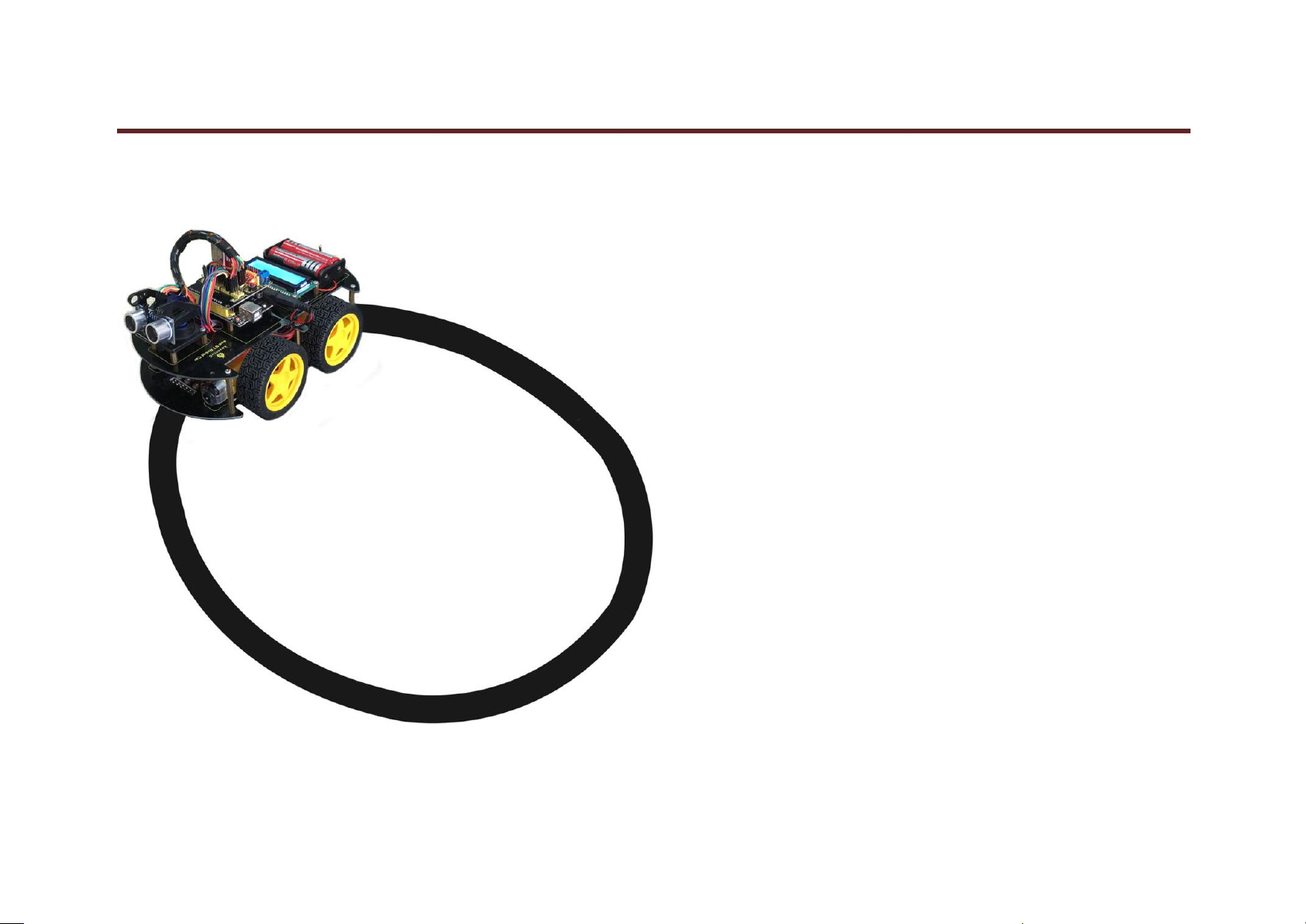
keyestudio 4WD Bluetooth Multi-functional Car
www.keyestudio.cc

keyestudio
Content
1. Introduction .............................................................................................................................................................................................................................................. 1
2. Parameters ................................................................................................................................................................................................................................................ 1
3. Project List ............................................................................................................................................................................................................................................... 2
4. BOM ........................................................................................................................................................................................................................................................ 3
5. Installation Method .................................................................................................................................................................................................................................. 9
6. Address of Assembly Video ................................................................................................................................................................................................................... 29
7. Address of Demonstration Video ........................................................................................................................................................................................................... 29
8. Project Details ........................................................................................................................................................................................................................................ 30
Project 1:Line Tracking Sensor .......................................................................................................................................................................................................... 30
Project 2: Ultrasonic Sensor ............................................................................................................................................................................................................... 34
Project 3: Digital IR Receiver Module ............................................................................................................................................................................................. 40
Project 4: Servo Motor ....................................................................................................................................................................................................................... 45
Project 5: Bluetooth Module .............................................................................................................................................................................................................. 52
Project 6: L298N Motor Driver ......................................................................................................................................................................................................... 57
Project 7:keyestudio 1602 I2C Module ........................................................................................................................................................................................... 63
Project 8: Line Tracking of Smart Car ............................................................................................................................................................................................... 68
Project 9: Ultraviolet Obstacle Avoidance of Smart Car.................................................................................................................................................................... 80
Project 10:IR Remote Control of Smart Car ................................................................................................................................................................................... 91
Project 11:Distance Detecting of Smart Car ................................................................................................................................................................................. 101
Project 12:Bluetooth Remote Control of Smart Car ..................................................................................................................................................................... 117
Project 13:: 5 in 1 (Line Tracking, Obstacle Avoidance, Bluetooth and IR Remote Control, Distance Detecting ) Multi-functional Car ................................... 127
1.
www.keyestudio.cc

keyestudio
1
1. Introduction
keyestudio 4WD Bluetooth Multi-functional Car is a learning application development system based on microcontroller and with ATmega-328 as core. It has
functions of line tracking, obstacle avoidance, IR remote control , Bluetooth remote control and detecting distance. This kit contains plenty of interesting programs
and can extend an external circuit module to increase more functions of this car. The kit aims to disengage users from boring theories and obtain capacity of system
development when they are learning Arduino.
2. Parameters
1.Motor: Voltage: 6-9V Reduction Ratio: 1:48
2.Choosing L298N driver module as control motor, separated from microcontrollor
3.Three line tracking modules, having higher precision when detecting white and black lines,able to realize anti-falling
4.IR remote control module making up a remote control system of the car
5.Using ultrasonic module to realize obstacle avoidance
6.Pairing mobile phone Bluetooth with Bluetooth remote control module to control the car
7.Able to connect with external voltage at 7~12V,and equip with various sensors to complete different functions as much as possible
www.keyestudio.com

2
3. Project List
Project 1:Line Tracking Sensor
Project 2:Ultrasonic Sensor
Project 3: Digital IR Receiver Module
Project 4: Servo Motor
Project 5: Bluetooth Module
Project 6: L298N Motor Driver
Project 7: I2C 1602 LCD
Project 8:Line Tracking of Smart Car
Project 9:Obstacle Avoidance of Smart Car
Project 10:IR Remote Control of Smart Car
Project 11:Distance Detecting of Smart Car
Project 12:Bluetooth Remote Control of Smart Car
Project 13:5 in 1 Multi-functional Car
keyestudio
www.keyestudio.com

3
4. BOM
No.
Product Name
Quantity
Picture
1
keyestudio UNO R3
1 2
keyestudio Shield V5
1 3
keyestudio L298N Motor Shield
1
keyestudio
www.keyestudio.com

keyestudio
4
4
keyestudio Bluetooh HC-06
1
5
I2C 1602 LCD
1
6
keyestudio Line Tracking Sensor
3
7
HC-SR04 Ultrasonic Sensor
1
8
keyestudio Digital IR Receiver Module
1
www.keyestudio.com

keyestudio
5
9
4WD Top PCB
1
10
4WD Bottom PCB
1 11
Servo Motor
1
12
Servo Plastic Platform
1
13
Remote Control of Chip
1
www.keyestudio.com
keyestudio
6
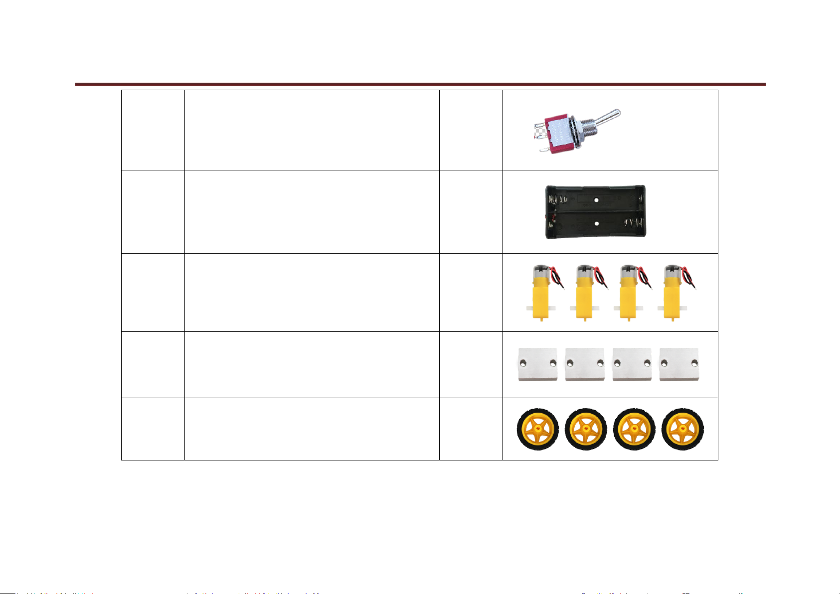
14
Toggle Switch
1
15
18650 Battery Case
1
16
Mental Motor
4
17
Motor Fixed Part
4
18
Plastic Tire
4
www.keyestudio.com

keyestudio
7
19
Copper Pillar 40MM
6
20
Copper Pillar 10MM
16
21
USB Cable
1 22
Dupont Line
30
www.keyestudio.com
keyestudio
8
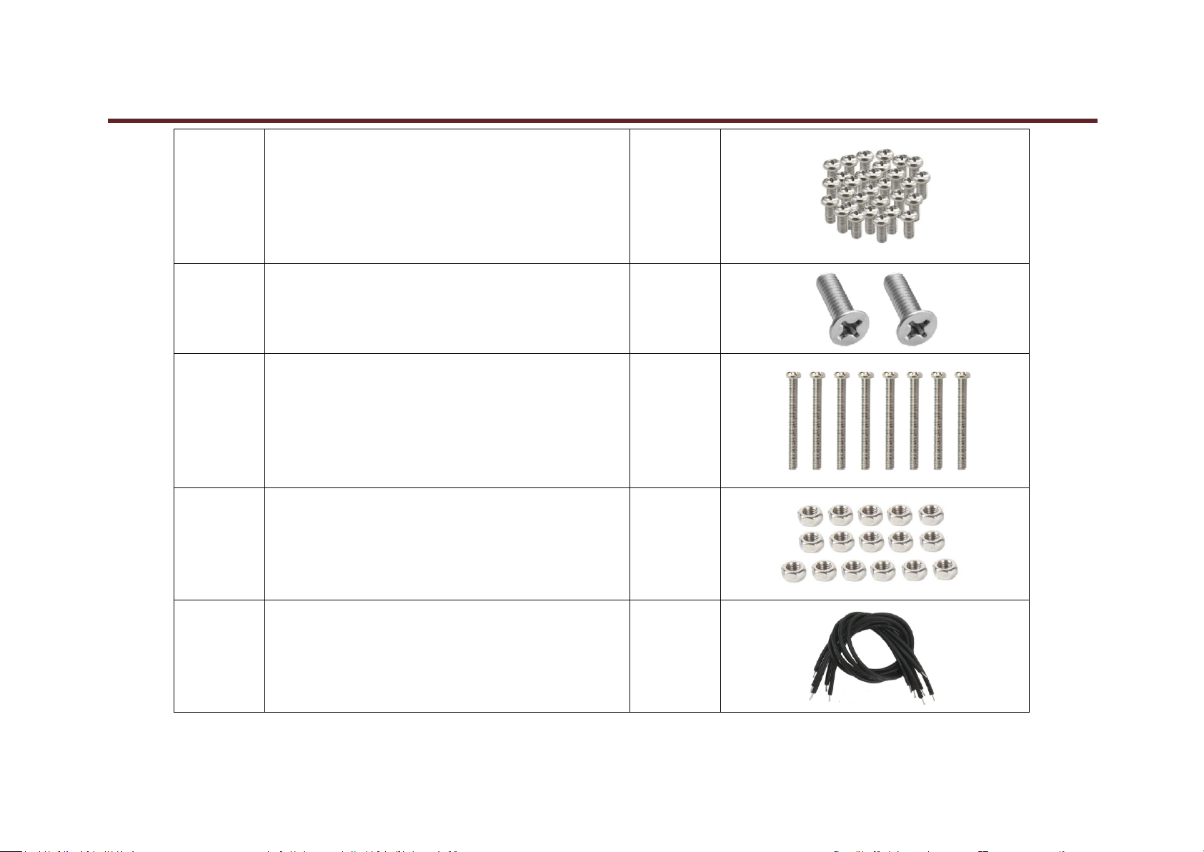
23
M3*6MM Round Head Screw
60
24
M3*6MM Flat Head Screw
2
25
M3*30MM Round Head Screw
8
26
3MM Nut
16
27
Connector Wire (150mm, Black)
6
www.keyestudio.com

9
28
Connector Wire (150mm, Red)
6
29
Winding Wire (12CM)
1
5. Installation Method
keyestudio
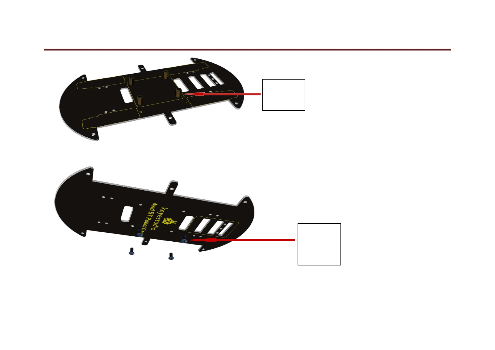
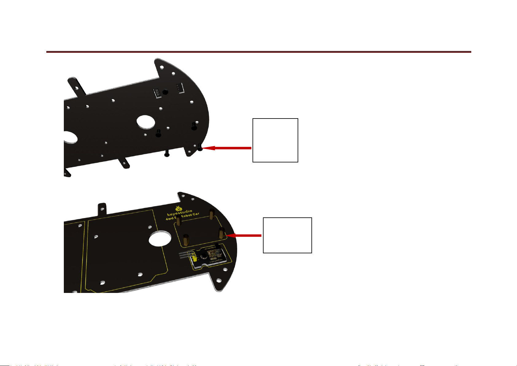
1. Plug 4 10MM copper pillars into bottom PCB.
www.keyestudio.com
keyestudio
10
4pcs
Copper Pillar
10MM
4pcs
M3*6MM
Round Head
Screw
2. 4 M3*6MM round head screw is slotted into the pillars.
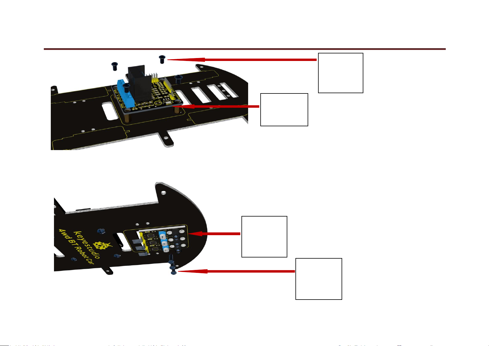
3. keyestudio L298N motor shield is bolted to the 4 pillars with 4 screws
www.keyestudio.com
keyestudio
11
keyestudio
L298N Motor
Shield
4pcs
M3*6MM
Round Head
Screw
3 pcs
keyestudio
Line Tracking
Sensor
3pcs
M3*6MM
Round Head
Screw
4. Attach 3 line tracking sensors to bottom PCB using 3 screws.
5. Fix the line tracking sensors with 3 nuts on the back.
www.keyestudio.com

12
3 pcs
3MM Nut
4 pcs
Motor Fixed Part
6.Direct 4 motor fixed parts to the holes on bottom PCB.
keyestudio
www.keyestudio.com

keyestudio
13
8 pcs
M3*6MM
Round Head
Screw
7. Bolt the motor fixed parts to bottom PCB with 8 screws.
8. Place 4 mental motors on PCB near the motor fixed parts.
www.keyestudio.com

14
4pcs
Mental Motor
8 pcs
3MM Nut
8 pcs
M3*30MM
Round Head
Screw
9. Attach 4 motors to bottom PCB using 8 screws and 8 nuts.
keyestudio
www.keyestudio.com

15
10. Plug 4 tires into the motors.
4pcs
Plastic Tire
6pcs
M3*6MM
Round Head
Screw
11. Insert 6 screws into 6 holes around bottom PCB.
keyestudio
12. Slot 6 pillars into the screws.
www.keyestudio.com

16
6pcs
Copper Pillar
40MM
keyestudio
Digital
IR Receiver
Module
1pcs
M3*6MM
Round Head
Screw
13. Attach IR receiver module to top PCB using a screw.
keyestudio
14. Twist a nut to the screw to fix IR receiver module.
www.keyestudio.com

keyestudio
17
1 pcs
3MM Nut
15. Insert 4 screws into the holes of top PCB.
www.keyestudio.com
keyestudio
18
4pcs
M3*6MM
Round Head
Screw
4pcs
Copper Pillar
10MM
16. 4 pillars are slotted into the screws.
www.keyestudio.com
keyestudio
19
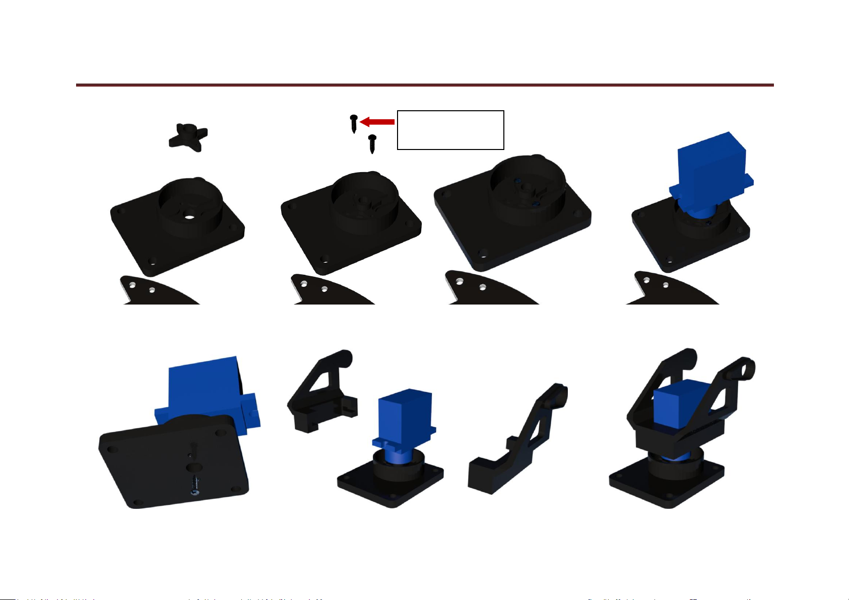
2pcs M2*8
Tapping Screw
17. First cut the plastic object into a cross to put into the part completely,and then install platform and motor step by step according following figures.
www.keyestudio.com

keyestudio
20
HC-SR04
Ultrasonic Sensor
4pcs
M3*6MM
Round Head
Screw
18. Attach ultrasonic sensor to the platform using wingding wire.
19. Bolt the whole platform to 4 pillars on top PCB with 4 screws.
www.keyestudio.com

keyestudio
21
2pcs
M3*6MM
Flat Head
Screw
18650
Battery
Case
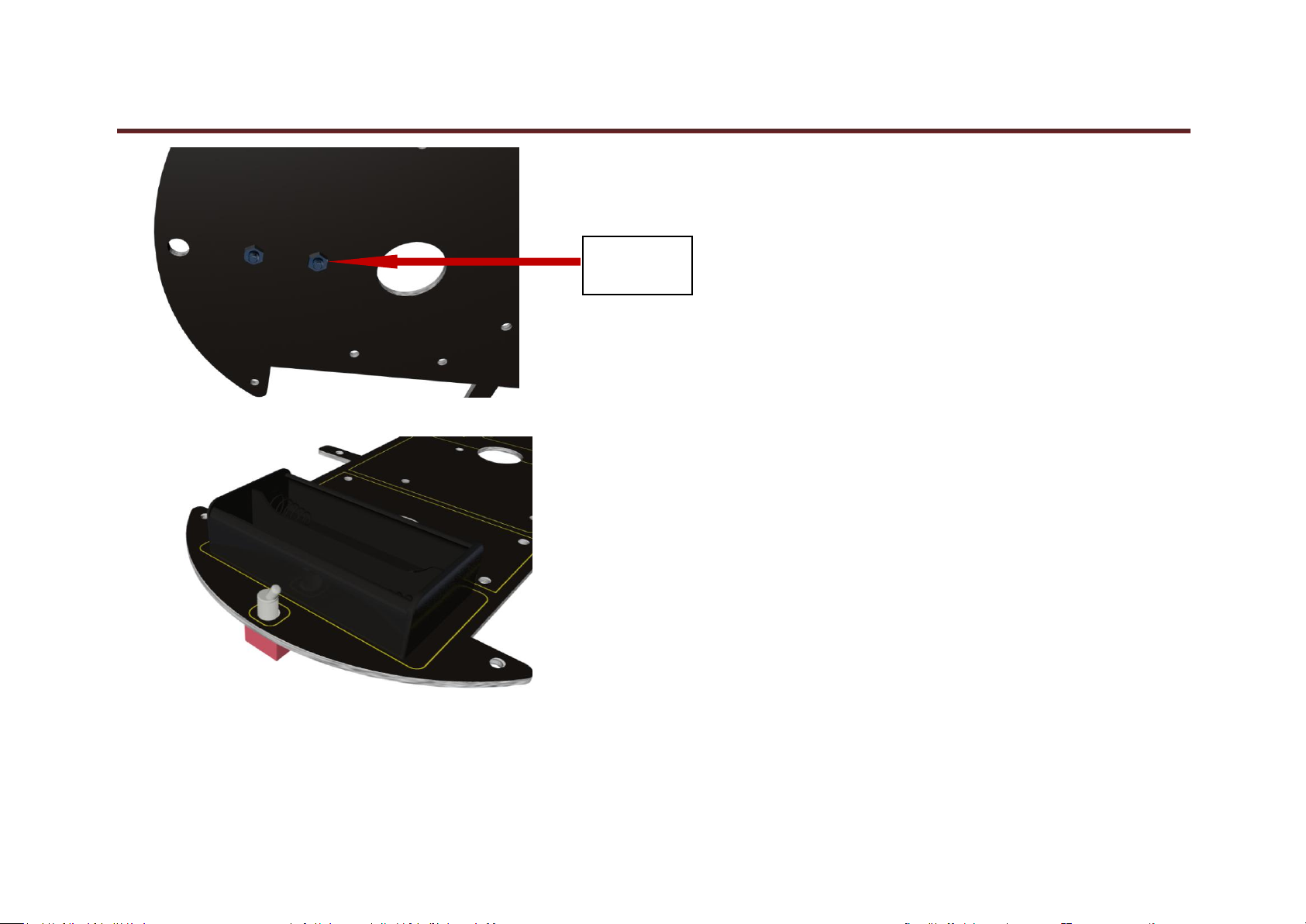
20.Battery case is bolted to top PCB on the end with 2 screws.
21. Twist 2 nuts to fix the battery case.
www.keyestudio.com
22
2pcs
3MM Nut
22. Install toggle switch on top PCB.
keyestudio
www.keyestudio.com

keyestudio
23
Toggle
Switch
8pcs
M3*6MM
Round Head
Screw
23. Insert 8 screws into the holes of the middle part on top PCB.
24. Slot 8 pillars into 8 screws.
www.keyestudio.com

keyestudio
24
8pcs
Copper Pillar
10MM
keyestudio
UNO R3
I2C 1602
LCD
25.Plug LCD and UNO R3 into the 8 pillars.
26. Attach LCD and UNO R3 to the pillars using screws.
www.keyestudio.com

keyestudio
25
8pcs
M3*6MM
Round Head
Screw
keyestudio
Shield V5
27. Plug shield V5 into UNO R3.
www.keyestudio.com
keyestudio
26
keyestudio
Bluetooh
HC-06
4WD
Top PCB
4WD
Bottom PCB
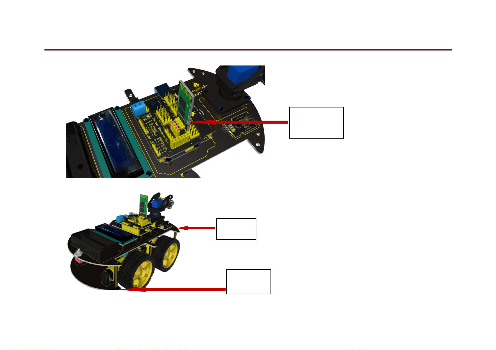
28. Plug Bluetooh HC-06 into shield V5.
29. Plug top board into bottom board.
www.keyestudio.com

keyestudio
27
6pcs
M3*6MM
Round Head
Screw
30. Fix top and bottom board using 6 screws.
31. Installation is complete,shown as following figure.
www.keyestudio.com

keyestudio
28
www.keyestudio.com

keyestudio
29
6. Address of Assembly Video
http://www.keyestudio.com/wp/2016/09/ks0192
7. Address of Demonstration Video
http://www.keyestudio.com/wp/2016/09/ks0192-keyestudio-4wd-bluetooth-multi-functional-
car-demonstration-video/
www.keyestudio.com
30
8. Project Details
Project 1:Line Tracking Sensor
keyestudio
Introduction:
This Line Tracking Sensor can detect white lines in black and black lines in white. The single line-tracking signal provides a stable output signal TTL for a more
accurate and more stable line. Multi-channel option can be easily achieved by installing required line-tracking robot sensors.
www.keyestudio.com

keyestudio
31
Specification:
Power Supply: +5V
Operating Current: <10mA
Operating Temperature Range: 0°C ~ + 50°C
Output Interface: 3-wire interface (1 - signal, 2 - power, 3 - power supply negative)
Output Level: TTL level
Connection Diagram:
www.keyestudio.com

keyestudio
32
Sample Code:
*******************************************************************************
const int sensorPin = 3; // the number of the sensor pin
const int ledPin = 13; // the number of the LED pin
int sensorState = 0; // variable for reading the sensor status
void setup() {
pinMode(ledPin, OUTPUT);
pinMode(sensorPin, INPUT); }
void loop(){
// read the state of the sensor value:
sensorState = digitalRead(sensorPin);
// if the sensorState is HIGH:
if (sensorState == HIGH) {
digitalWrite(ledPin, HIGH);
}
else {digitalWrite(ledPin, LOW);
}}
*******************************************************************************
Result
After power-on, power indicator D1 is on. When you block the sensing part of line tracking sensor with black paper, LED on the sensor is off as shown in Figure 1.
When you block it with white paper, LED is on as shown in Figure 2.
www.keyestudio.com

keyestudio
33
Figure 1 Figure 2
www.keyestudio.com

keyestudio
34
Project 2: Ultrasonic Sensor
Introduction:
The HC-SR04 Ultrasonic Sensor is a very affordable proximity/distance sensor that has been used mainly for object avoidance in various robotics projects. It
essentially gives your Arduino eyes / spacial awareness and can prevent your robot from crashing or falling off a table. It has also been used in turret applications,
water level sensing, and even as a parking sensor. This simple project will use the HC-SR04 sensor with an Arduino and a Processing sketch to provide a neat little
interactive display on your computer screen.
Specification:
Working Voltage: DC 5V
www.keyestudio.com

35
Working Current: 15mA
Working Frequency: 40KHz
Max Range: 4m
Min Range: 2cm
Measuring Angle: 15 degree
Trigger Input Signal: 10µS TTL pulse
Size: 46*20.4mm
Weight: 9g
Connection Diagram:
keyestudio
www.keyestudio.com

keyestudio
36
Sample Code:
VCC to arduino 5v
GND to arduino GND
Echo to Arduino pin 7
Trig to Arduino pin 8
*******************************************************************************
#define echoPin 7 // Echo Pin
#define trigPin 8 // Trigger Pin
#define LEDPin 13 // Onboard LED
www.keyestudio.com

keyestudio
37
int maximumRange = 200; // Maximum range needed
int minimumRange = 0; // Minimum range needed
long duration, distance; // Duration used to calculate distance
void setup() {
Serial.begin (9600);
pinMode(trigPin, OUTPUT);
pinMode(echoPin, INPUT);
pinMode(LEDPin, OUTPUT); // Use LED indicator (if required)
}
void loop() {
/* The following trigPin/echoPin cycle is used to determine the
distance of the nearest object by bouncing soundwaves off of it. */
digitalWrite(trigPin, LOW);
delayMicroseconds(2);
digitalWrite(trigPin, HIGH);
delayMicroseconds(10);
digitalWrite(trigPin, LOW);
duration = pulseIn(echoPin, HIGH);
//Calculate the distance (in cm) based on the speed of sound.
distance = duration/58.2;
www.keyestudio.com

keyestudio
38
if (distance >= maximumRange || distance <= minimumRange){
/* Send a negative number to computer and Turn LED ON
to indicate "out of range" */
Serial.println("-1");
digitalWrite(LEDPin, HIGH);
}
else {
/* Send the distance to the computer using Serial protocol, and
turn LED OFF to indicate successful reading. */
Serial.println(distance);
digitalWrite(LEDPin, LOW);
}
//Delay 50ms before next reading.
delay(50);
}
*******************************************************************************
Result
After connection and uploading, when ultrasonic sensor senses obstacle within sensing area, it is measuring the distance between itself and obstacle and the value of
distance is displayed on serial monitor as shown in bellow figure.
www.keyestudio.com

keyestudio
39
www.keyestudio.com
keyestudio
40
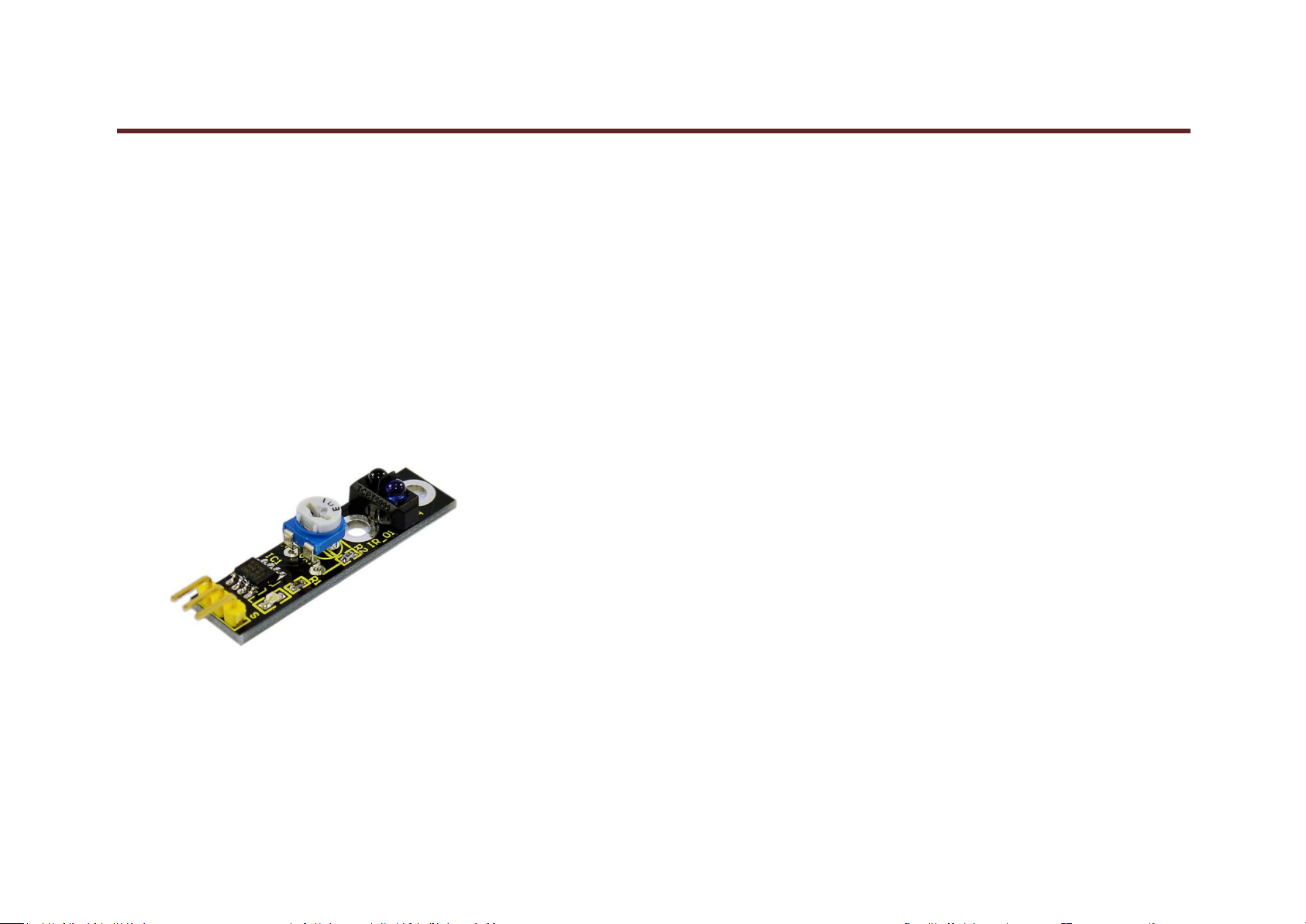
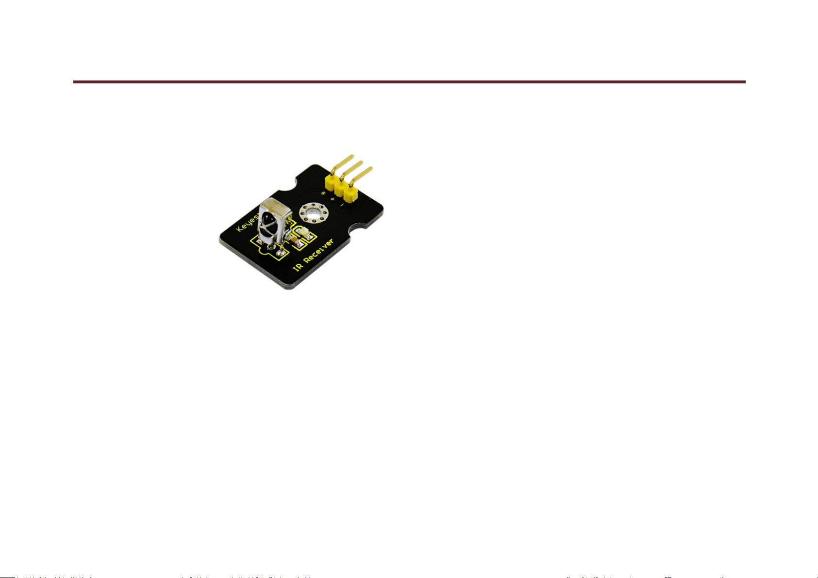
Project 3: Digital IR Receiver Module
Introduction:
IR is widely used in remote control. With this IR receiver, Arduino project is able to receive command from any IR remoter controller if you have the right
decoder. Well, it will be also easy to make your own IR controller using IR transmitter.
Specification:
Power Supply: 5V
Interface: Digital
Modulate Frequency: 38Khz
Module Interface Socket: JST PH2.0
NOTE: In the sample code below Digital pin 11 is in use, you may either change your wiring or change the sample code to match.
www.keyestudio.com

41
Connection Diagram:
keyestudio
Sample Code:
*******************************************************************************
Get library from: https://github.com/shirriff/Arduino-IRremote
#include <IRremote.h>
www.keyestudio.com

keyestudio
42
int RECV_PIN = 11;
IRrecv irrecv(RECV_PIN);
decode_results results;
void setup()
{
Serial.begin(9600);
irrecv.enableIRIn(); // Start the receiver
}
void loop() {
if (irrecv.decode(&results)) {
Serial.println(results.value, HEX);
irrecv.resume(); // Receive the next value
}
}
*******************************************************************************
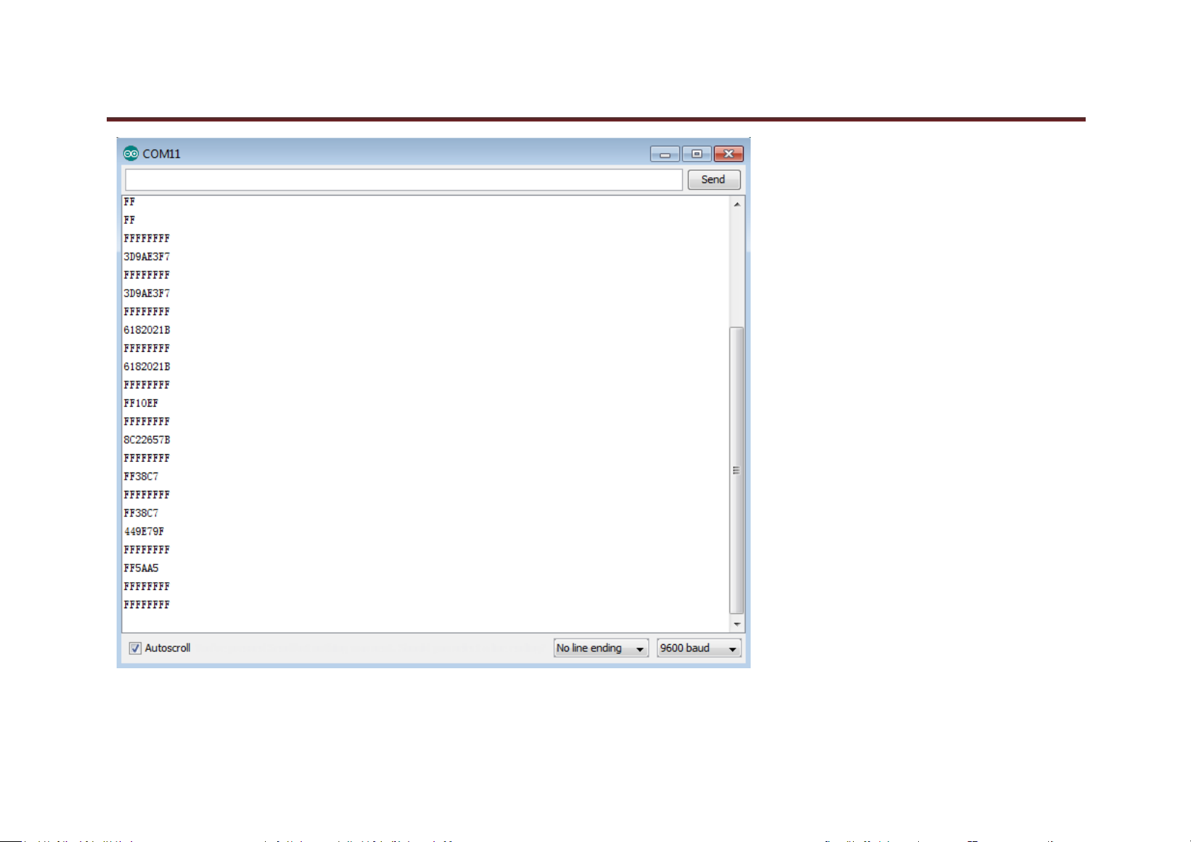
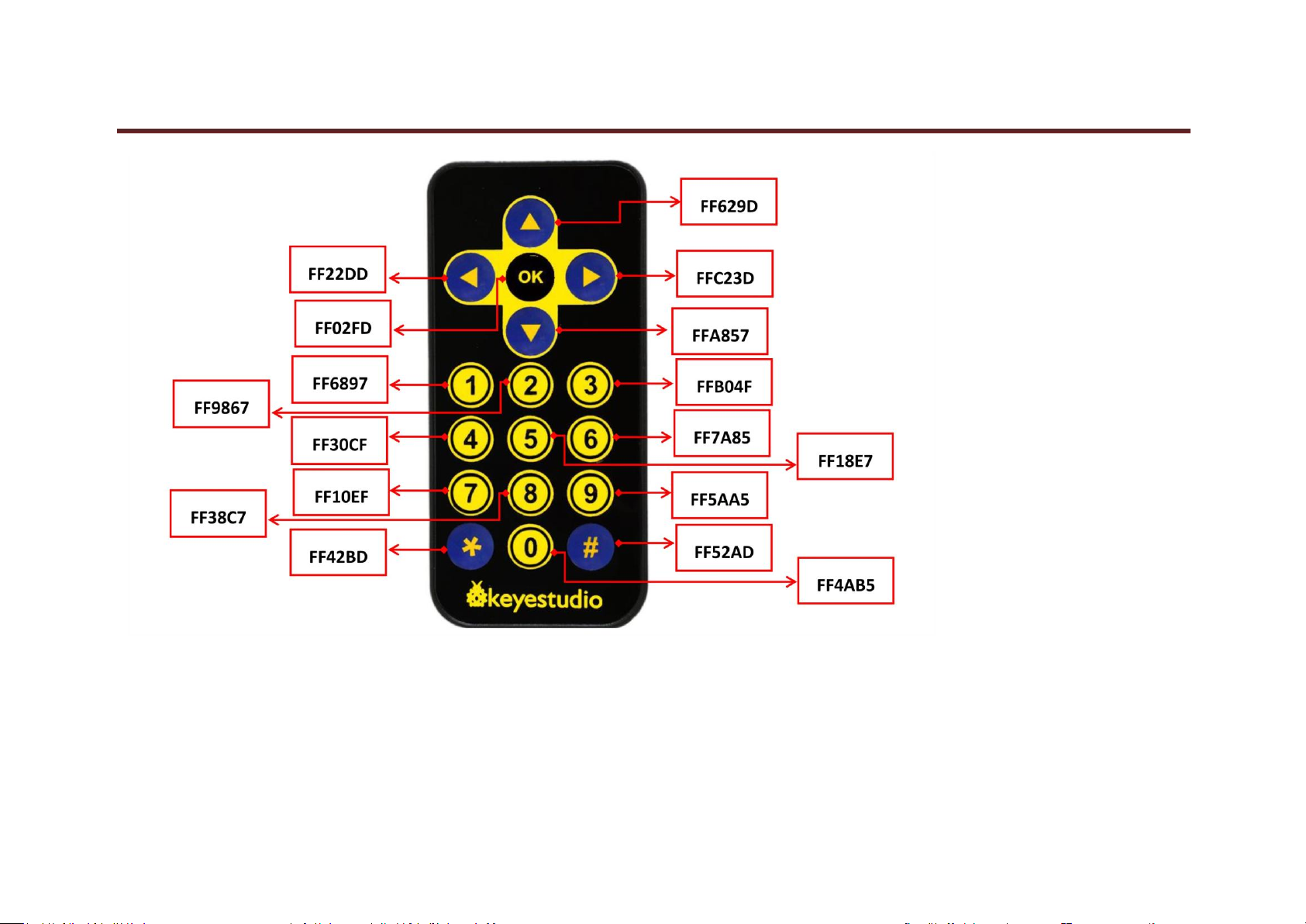
Result
In this project, we need to use a IR remote control which has 17 functional key and its launching distance is 8 meters at most, proper to control various devices
indoors. This project is actually to decode remote control signal. After connection and uploading codes, aim at IR receiving module and press the key, finally you
can see corresponding codes. If you press the key too long, it will show messy codes easily as shown in bellow figure.
www.keyestudio.com
keyestudio
43
www.keyestudio.com
keyestudio
44
www.keyestudio.com
45
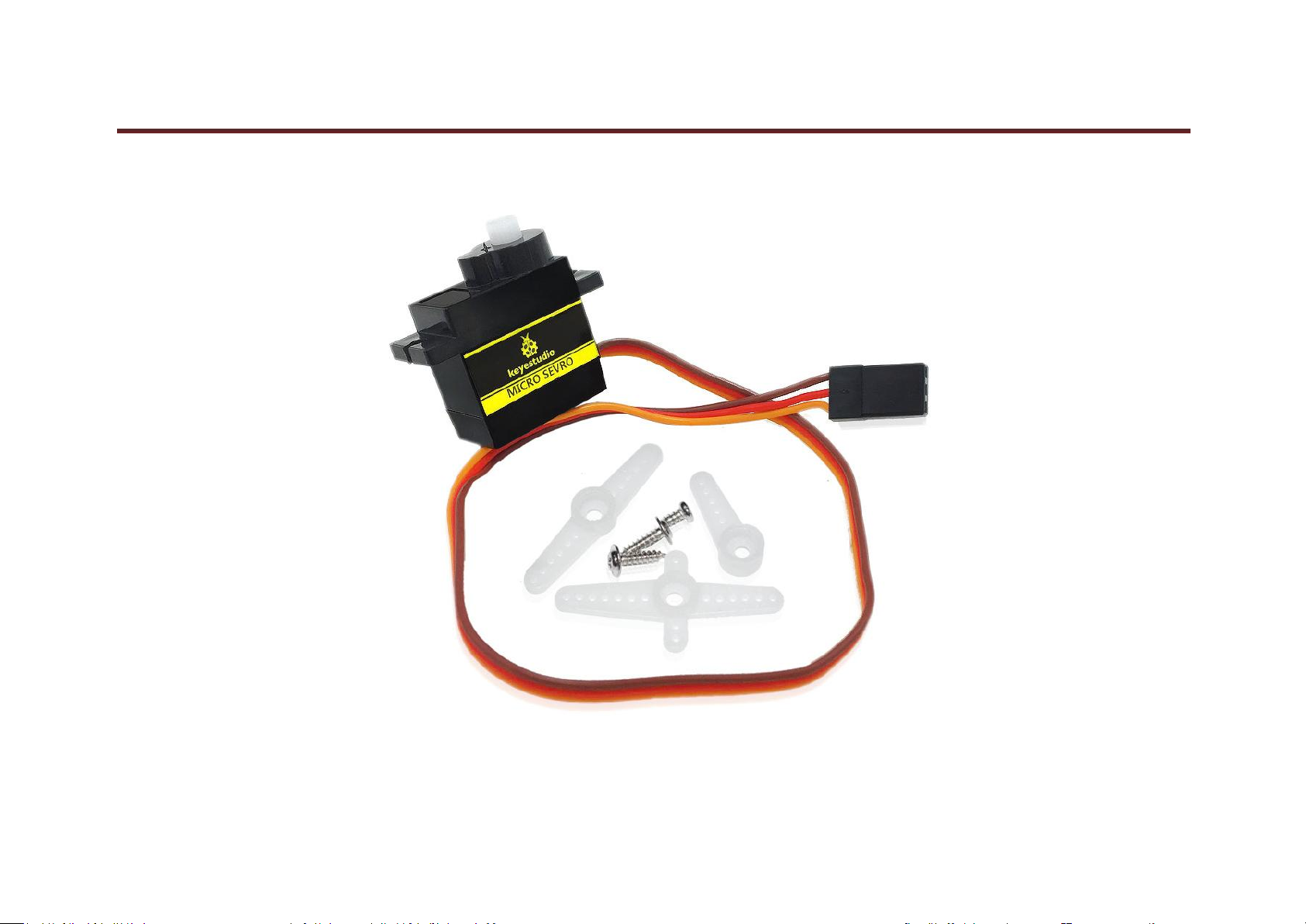
Project 4: Servo Motor
keyestudio
www.keyestudio.com

keyestudio
46
Introduction
Servomotor is a position control rotary actuator. It mainly consists of housing, circuit board, core-less motor, gear and position
sensor. The receiver or MCU outputs a signal to the servomotor. The motor has a built-in reference circuit that gives out reference signal, cycle of 20ms and width
of 1.5ms. The motor compares the acquired DC bias voltage to the voltage of the potentiometer and outputs a voltage difference. The IC on the circuit board will
decide the rotate direction accordingly and drive the core-less motor. The gear then pass the force to the shaft. The sensor will determine if it has reached the
commanded position according to the feedback signal. Servomotors are used in control systems that requires to have and maintain different angles. When the
motor speed is definite, the gear will cause the potentiometer to rotate. When the voltage difference reduces to zero, the motor stops. Normally, the rotation
angle range is among 0-180 degrees.
Servomotor comes with many specifications. But all of them have three connection wires, distinguished by brown, red, orange colors(different brand may have
different color). Brown one is for GND, red one for power positive, orange one for signal Line.
The rotate angle of the servo motor is controlled by regulating the duty cycle of the PWM(Pulse-Width Modulation) signal. The standard cycle of the PWM signal
is 20ms(50Hz). Theoretically, the width is distributed between 1ms-2ms, but in fact, it's between 0.5ms-2.5ms. The width corresponds the rotate angle from 0° to
180°. But note that for different brand motor, the same signal may have different rotate angle.
www.keyestudio.com

keyestudio
47
After some basic knowledge, let's learn how to control a servomotor. For this experiment, you only need a servomotor and several jumper wires.
Connection & sample program
There are two ways to control a servomotor with Arduino. One is to use a common digital sensor port of Arduino to produce square wave with different duty cycle
to simulate PWM signal and use that signal to control the positioning of the motor. Another way is to directly use the Servo function of the Arduino to control the
motor. In this way, the program will be easier but it can only control two-contact motor because for the servo function, only digital pin 9 ang 10 can be used. The
Arduino drive capacity is limited. So if you need to control more than one motor, you will need external power.
Connection Diagram:
www.keyestudio.com

keyestudio
48
Sample Code:
*******************************************************************************
int servopin=9;// select digital pin 9 for servomotor signal line
www.keyestudio.com

keyestudio
49
int myangle;// initialize angle variable
int pulsewidth;// initialize width variable
int val;
void servopulse(int servopin,int myangle)// define a servo pulse function
{
pulsewidth=(myangle*11)+500;// convert angle to 500-2480 pulse width
digitalWrite(servopin,HIGH);// set the level of servo pin as “high”
delayMicroseconds(pulsewidth);// delay microsecond of pulse width
digitalWrite(servopin,LOW);// set the level of servo pin as “low”
delay(20-pulsewidth/1000);
}
void setup()
{
pinMode(servopin,OUTPUT);// set servo pin as “output”
Serial.begin(9600);// connect to serial port, set baud rate at “9600”
Serial.println("servo=o_seral_simple ready" ) ;
}
void loop()// convert number 0 to 9 to corresponding 0-180 degree angle, LED blinks corresponding number of time
{
val=Serial.read();// read serial port value
if(val>='0'&&val<='9')
{
val=val-'0';// convert characteristic quantity to numerical variable
val=val*(180/9);// convert number to angle
Serial.print("moving servo to ");
Serial.print(val,DEC);
www.keyestudio.com

keyestudio
50
Serial.println();
for(int i=0;i<=50;i++) // giving the servo time to rotate to commanded position
{
servopulse(servopin,val);// use the pulse function
}
}
}
*******************************************************************************
Result
When you input a number on serial monitor, the motor rotates to an angle which is equal to the number input, and the angle dimension will be displayed on screen,
as shown in bellow figure.
www.keyestudio.com

keyestudio
51
www.keyestudio.com

keyestudio
52
Project 5: Bluetooth Module
Introduction:
This Bluetooth module can easily achieve serial wireless data transmission. Its operating frequency is among the most popular 2.4GHz ISM frequency band (i.e.
Industrial, scientific and medical). It adopts Bluetooth 2.1+EDR standard. In Bluetooth 2.1, signal transmit time of different devices stands at a 0.5 seconds interval
so that the workload of bluetooth chip can be reduced substantially and more sleeping time can be saved for bluetooth. This module is set with serial interface,
which is easy-to-use and simplifying overall design/development cycle.
www.keyestudio.com

keyestudio
53
Specification:
Bluetooth Protocol: Bluetooth 2.1+ EDR Standard
USB Protocol: USB v1.1/2.0
Operating Frequency: 2.4GHz ISM Frequency Band
Modulation Mode: Gauss Frequency Shift Keying
Transmit Power: ≤ 4dBm, Second Stage
Sensitivity: ≤-84dBm at 0.1% Bit Error Rate
Transmission Speed: 2.1Mbps(Max)/160 kbps(Asynchronous); 1Mbps/1Mbps(Synchronous)
Safety Feature: Authentication and Encryption
Supported Configuration: Bluetooth Serial Port (major and minor)
Supply Voltage: +3.3 VDC 50mA
Operating Temperature: -20 to 55℃
www.keyestudio.com

54
Connection Diagram:
keyestudio
www.keyestudio.com

keyestudio
55
Sample Code:
*******************************************************************************
int val;
int ledpin=13;
void setup()
{
Serial.begin(9600);
pinMode(ledpin,OUTPUT);
}
void loop()
{ val=Serial.read();
if(val=='a')
{
digitalWrite(ledpin,HIGH);
delay(250);
digitalWrite(ledpin,LOW);
delay(250);
Serial.println("keyestudio");
}
}
*******************************************************************************
Result
After power-on, power indicator D1 is on, and LED on Bluetooth module is blinking; open Bluetooth on mobile phone, pair them, input 1234, and finish pairing as
shown in Figure 1 ; open APP—Bluetooth serial communication assistant, connect it to Bluetooth, select normal mode, complete connection, and LED on
www.keyestudio.com

keyestudio
56
Bluetooth module is on as shown in Figure 2; input an “a” in the assistant, and display “keyesdudio” in it as shown in Figure 3.
Figure 1 Figure 2 Figure 3
www.keyestudio.com

keyestudio
57
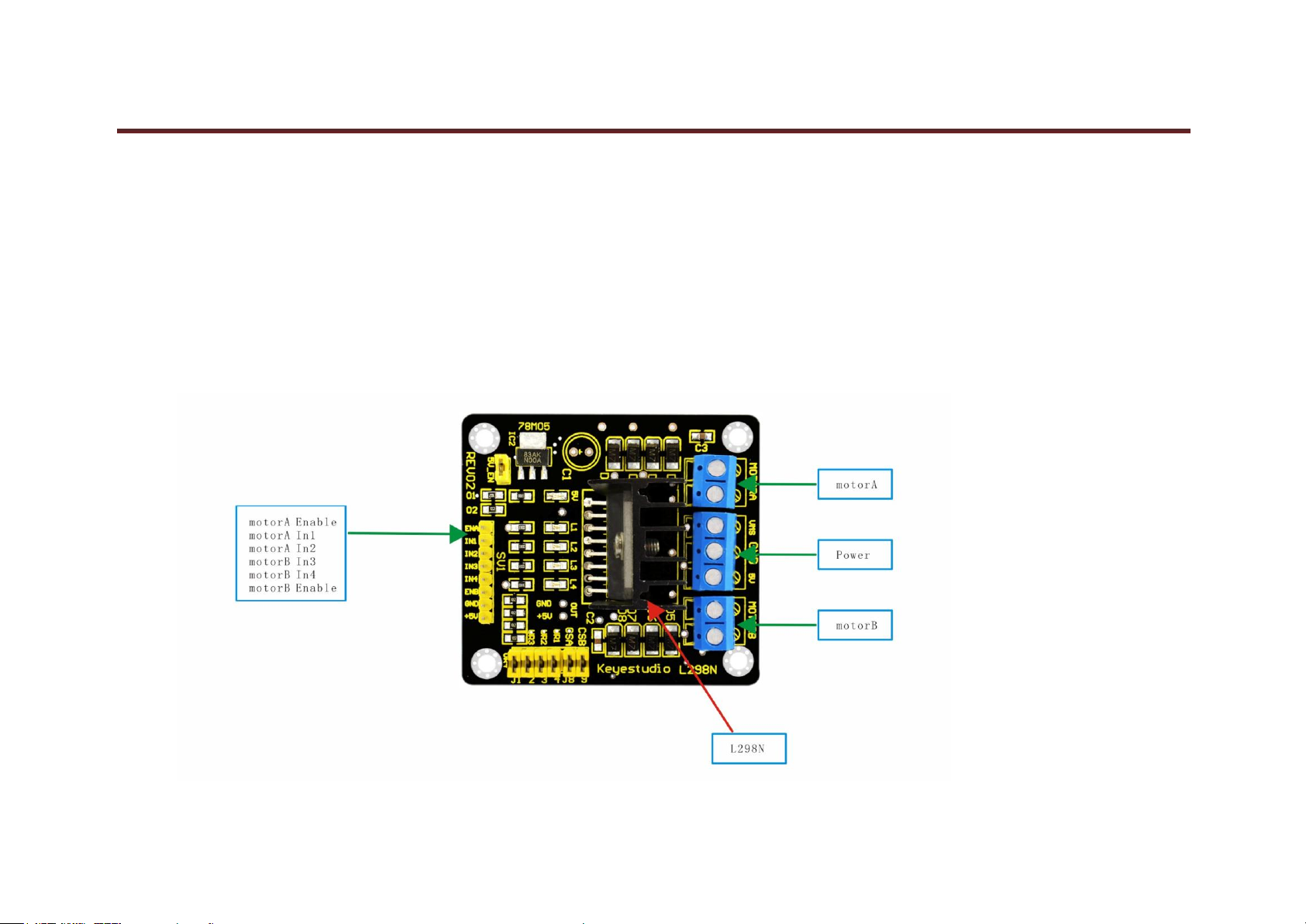
Project 6: L298N Motor Driver
Introduction:
Using L298N made by ST Company as the control chip, the module has characteristics of strong driving ability, low calorific value and strong anti-interference
ability.
This module can use built-in 78M05 for electric work via a driving power supply part. But to avoid the damage of the voltage stabilizing chip, please use an
external 5V logic supply when using more than 12V driving voltage.
Using large capacity filter capacitor, this module can follow current to protect diodes, and improve reliability.
Specification:
www.keyestudio.com
58
Working Mode: H bridge (double lines)
Control Chip: L298N (ST)
Logical Voltage: 5V
Driving Voltage: 5V-35V
Logical Current: 0mA-36mA
Driving Current: 2A (MAX single bridge)
Storage Temperature: (-20 °C)-(+135 °C)
Maximum Power: 25W
Weight: 30g
Periphery Dimension: 43 x 43 x 27 mm(L x W x H)
keyestudio
www.keyestudio.com
59
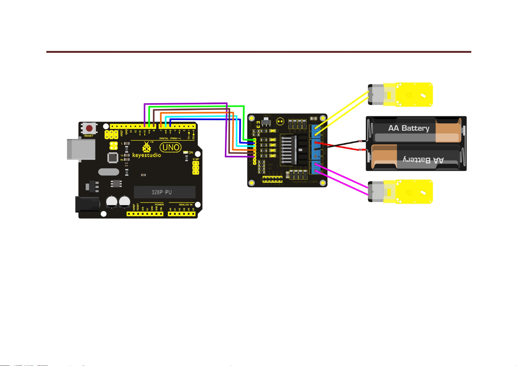
Circuit Connection:
keyestudio
www.keyestudio.com

keyestudio
60
Sample Code:
*******************************************************************************
int IN1=5;
int IN2=6;
www.keyestudio.com

61
int IN3=7;
int IN4=8;
int ENA=9;
int ENB=10;
void setup()
{
for (int i = 5; i <11; i ++)
{
pinMode(i, OUTPUT);
}
}
void loop()
{
// rotate CW
digitalWrite(IN1,LOW);
digitalWrite(IN2,HIGH);
analogWrite(ENA,200);
digitalWrite(IN3,LOW);
digitalWrite(IN4,HIGH);
analogWrite(ENB,200);
delay(1000);
// pause for 1S
analogWrite(ENA,0);
analogWrite(ENB,0);
delay(1000);
// rotate CCW
keyestudio
www.keyestudio.com

keyestudio
62
digitalWrite(IN1,HIGH);
digitalWrite(IN2,LOW);
analogWrite(ENA,100);
digitalWrite(IN3,HIGH);
digitalWrite(IN4,LOW);
analogWrite(ENB,100);
delay(1000);
// pause for 1S
analogWrite(ENA,0);
analogWrite(ENB,0);
delay(1000);
}
*******************************************************************************
Result
After connection and power-on, two motors rotate clockwise for 1 second at a speed of 200 (PWM value is 200) and then stop for 1 second; two motors rotate
anticlockwise for 1 second at a speed of 100 (PWM value is 100) and then stop for 1 second; circulating like this.
www.keyestudio.com

63
Project 7:keyestudio 1602 I2C Module
keyestudio
www.keyestudio.com

keyestudio
64
Introduction:
This is great LCD display compatible with arduino. With limited pin resources, your project will quickly run out of resources using normal LCDs. With this I2C
interface LCD module, you only need 2 lines (I2C)to display the information.If you already have I2C devices in your project, this LCD module actually cost no
more resources at all. The address can be set 0x27.
Specification:
I2C Address: 0x27
Back Lit (Blue with white char color)
Supply Voltage: 5V
Interface:I2C/TWI x1,Gadgeteer interface x2
Adjustable Contrast
Size:82x35x18 mm
Connection Diagram:
I602 is equipped with 4 pins in total. SCL should be connected to analog 5, SDA to analog 4, VCC to +5V and GND to ground.
connection :
www.keyestudio.com

keyestudio
65
Sample Code:
*******************************************************************************
Get libraries of Wire and LiquidCrystal_I2C from :
http://7326097.s21d-7.faiusrd.com/0/ABUIABAAGAAg7uTNvgUojdGEywY?f=LiquidCrystal_I2C++Wire.zip&v=1473475182
//Compatible with the Arduino IDE 1.0
//Library version:1.1
www.keyestudio.com

keyestudio
66
#include <Wire.h>
#include <LiquidCrystal_I2C.h>
LiquidCrystal_I2C lcd(0x27,16,2); // set the LCD address to 0x27 for a 16 chars and 2 line display
void setup()
{
lcd.init(); // initialize the lcd
lcd.init();
// Print a message to the LCD.
lcd.backlight();
lcd.setCursor(3,0);
lcd.print("Hello, world!");
lcd.setCursor(2,1);
lcd.print("keyestudio!");
}
void loop()
{}
*******************************************************************************
Result
After connection and uploading codes, the result of keyestudio 1602 I2C Module will be displayed as shown in bellow figure.
www.keyestudio.com

keyestudio
67
www.keyestudio.com
68
Project 8: Line Tracking of Smart Car
keyestudio
www.keyestudio.com

keyestudio
69
Introduction:
This project introduces a simple and automatic line tracking system of a car based on Arduino microcontroller.This car ,regarding UNO as main control, detect
black line by IR photoelectric sensor and send the feedback to Arduino. Arduino will analyses the feedback signal and then control the driver motor to adjust the
car diversion. Finally the car is able to go around the black line automatically. In addition, you can observe the state of the car through keyestudio 1602 I2C
Module.
Principle:
1.Black absorbs most light. When the plane isn’t black, most IR emitted by the sensor is reflected back. So the sensor output low level at 0.
2.When there is a sensor above black line, since reflectivity of black is small ,little IR is reflected back under demand that the sensor works. Therefore, the sensor
output 1.
3.We just need to know the output of the sensor is 1 or 0 with Arduino to detect black line.
4.Arduino control the motion of the car according to receiving signal. The system scheme is showed by following picture 1-1.
5.The system is composed of main control circuit, power supply, IR detecting module ,motor and driver module. The structure chart of the system is showed by
picture 2-1.
www.keyestudio.com

keyestudio
70
www.keyestudio.com
71
Schematic Diagram:
keyestudio
www.keyestudio.com

72
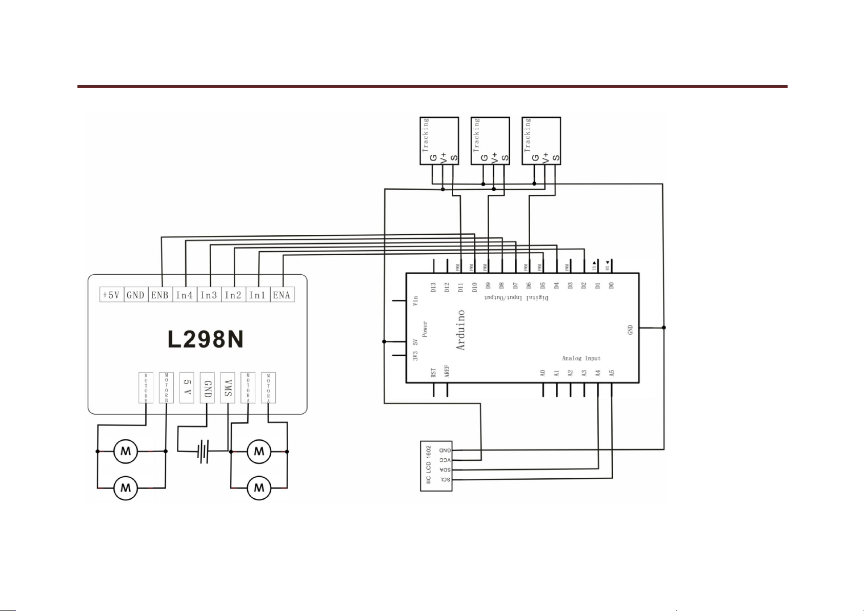
Connection Diagram:
keyestudio
www.keyestudio.com

keyestudio
73
Sample Code:
*******************************************************************************
#include <LiquidCrystal_I2C.h>
#include <Wire.h>
#define SensorLeft 6 //input pin of left sensor
#define SensorMiddle 9 //input pin of middle sensor
#define SensorRight 11 //input pin of right sensor
unsigned char SL; //state of left sensor
unsigned char SM; //state of middle sensor
unsigned char SR; //state of right sensor
#define Lpwm_pin 5 //pin of controlling speed---- ENA of motor driver board
#define Rpwm_pin 10 //pin of controlling speed---- ENA of motor driver board
int pinLB=2; //pin of controlling diversion----IN1 of motor driver board
int pinLF=4; //pin of controlling diversion----IN2 of motor driver board
int pinRB=7; //pin of controlling diversion----IN3 of motor driver board
int pinRF=8; //pin of controlling diversion----IN4 of motor driver board
unsigned char Lpwm_val =180;//the speed of left wheel at 180 in initialization
unsigned char Rpwm_val = 180;//the speed of right wheel at 180 in initialization
int Car_state=0; //state of car moving
LiquidCrystal_I2C lcd(0x27,16,2); // set the LCD address to 0x27 for a 16 chars and 2
void LCD1602_init(void)
{
lcd.init();
www.keyestudio.com

keyestudio
74
lcd.backlight();
lcd.clear();
}
void Sensor_IO_Config()
{
pinMode(SensorLeft,INPUT);
pinMode(SensorMiddle,INPUT);
pinMode(SensorRight,INPUT);
}
void Sensor_Scan(void)
{
SL = digitalRead(SensorLeft);
SM = digitalRead(SensorMiddle);
SR = digitalRead(SensorRight);
}
void M_Control_IO_config(void)//initialized function of IO of motor driver
{
pinMode(pinLB,OUTPUT); // pin 2--IN1 of motor driver board
pinMode(pinLF,OUTPUT); // pin 4--IN2 of motor driver board
pinMode(pinRB,OUTPUT); // pin 7--IN3 of motor driver board
pinMode(pinRF,OUTPUT); // pin 8--IN4 of motor driver board
pinMode(Lpwm_pin,OUTPUT); // pin 5 (PWM) --ENA of motor driver board
pinMode(Rpwm_pin,OUTPUT); // pin 10 (PWM) --ENB of motor driver board
}
void Set_Speed(unsigned char Left,unsigned char Right)//setting function of speed
{
www.keyestudio.com

keyestudio
75
analogWrite(Lpwm_pin,Left);
analogWrite(Rpwm_pin,Right);
}
void advance() // going forwards
{
digitalWrite(pinRB,LOW); // making motor move towards right rear
digitalWrite(pinRF,HIGH);
digitalWrite(pinLB,LOW); // making motor move towards left rear
digitalWrite(pinLF,HIGH);
Car_state = 1;
show_state();
}
void turnR() //turning on the right(dual wheels)
{
digitalWrite(pinRB,LOW); //making motor move towards right rear
digitalWrite(pinRF,HIGH);
digitalWrite(pinLB,HIGH);
digitalWrite(pinLF,LOW); //making motor move towards left front
Car_state = 4;
show_state();
}
void turnL() //turning on the left(dual wheels)
{
digitalWrite(pinRB,HIGH);
digitalWrite(pinRF,LOW ); //making motor move towards right front
digitalWrite(pinLB,LOW); //making motor move towards left rear
www.keyestudio.com

keyestudio
76
digitalWrite(pinLF,HIGH);
Car_state = 3;
show_state();
}
void stopp() //stop
{
digitalWrite(pinRB,HIGH);
digitalWrite(pinRF,HIGH);
digitalWrite(pinLB,HIGH);
digitalWrite(pinLF,HIGH);
Car_state = 5;
show_state();
}
void back() //back
{
digitalWrite(pinRB,HIGH); //making motor move towards right rear
digitalWrite(pinRF,LOW);
digitalWrite(pinLB,HIGH); //making motor move towards left rear
digitalWrite(pinLF,LOW);
Car_state = 2;
show_state() ;
}
void show_state(void) //showing current state of the car
{
lcd.setCursor(0, 1); //showing from second row
switch(Car_state)
www.keyestudio.com

keyestudio
77
{
case 1:lcd.print(" Go ");Serial.print("\n GO");
break;
case 2:lcd.print("Back ");Serial.print("\n Back");
break;
case 3:lcd.print("Left ");Serial.print("\n Left");
break;
case 4:lcd.print("Right");Serial.print("\n Right");
break;
case 5:lcd.print("Stop ");Serial.print("\n Stop");
break;
default:
break;
}
}
void setup()
{
LCD1602_init();
Sensor_IO_Config();
M_Control_IO_config(); //motor controlling the initialization of IO
Set_Speed(Lpwm_val,Rpwm_val); //setting initialization of speed
lcd.clear();
lcd.setCursor(0, 0); //cursor set in first row and first column,
lcd.print(" Wait Signal ");
stopp();
}
www.keyestudio.com

keyestudio
78
unsigned char old_SL,old_SM,old_SR;
void loop()
{
Sensor_Scan();
if (SM == HIGH)// middle sensor in black area
{
if (SL == LOW & SR == HIGH) // black on left, white on right, turn left
{
turnR();
}
else if (SR == LOW & SL == HIGH) // white on left, black on right, turn right
{
turnL();
}
else // white on both sides, going forward
{
advance();
}
}
else // middle sensor on white area
{
if (SL== LOW & SR == HIGH)// black on left, white on right, turn left
{
turnR();
}
else if (SR == LOW & SL == HIGH) // white on left, black on right, turn right
www.keyestudio.com

keyestudio
79
{
turnL();
}
else // all white, stop
{
back();
delay(100);
stopp() ;
}
}
}
*******************************************************************************
www.keyestudio.com

keyestudio
80
Project 9: Ultraviolet Obstacle Avoidance of Smart Car
Introduction:
This project ,regarding Arduino UNO as main control, detect front obstacle by ultrasonic sensor and platform motor, and send the feedback to Arduino. Arduino will
analyses the feedback signal and then control the driver motor to adjust the car diversion. Finally the car is able to avoid obstacle automatically and keep going.
www.keyestudio.com

keyestudio
81
Principle:
1.Ultrasonic detecting distance: one port emits high level more than 10 US. Once it outputting level, open potentiometer to time. When the port becomes low level,
read out current value. Use the time of detecting distance to calculate distance.
2.Use ultrasonic to detect the distance between obstacle and car, so that control the motion of the car according to the data.
3. If the distance between the car and obstacle is less than 20 cm, the car goes backward; if the distance is no less than 40 cm, the car goes forwards; if the distance is
less than 40cm , the motor turns to detect the distance between car and left obstacle or right obstacle; if the distance between car and left obstacle, the distance
between car and right obstacle are less than 15 cm, the car goes backward; if the distance between car and left obstacle is larger , the car turns left; if the distance
between car and left obstacle is less than or equal to the distance between car and right obstacle, the car turns right.
Schematic Diagram:
www.keyestudio.com

keyestudio
82
www.keyestudio.com

83
Connection Diagram:
keyestudio
Sample Code:
******************************************************************************
www.keyestudio.com

keyestudio
84
#include <Servo.h>
int pinLB = 2; // defining pin 12
int pinLF = 4; // defining pin 3
int pinRB = 7; // defining pin 13
int pinRF = 8; // defining pin 11
int Lpwm_pin = 5; //adjusting speed
int Rpwm_pin = 10; //adjusting speed //
unsigned char Lpwm_val = 200;
unsigned char Rpwm_val = 200;
////////////////////////////////
int inputPin = A0; // defining receiving pin of ultrasonic signal
int outputPin =A1; // defining emitting pin of ultrasonic signal
int Fspeedd = 0; // forward speed
int Rspeedd = 0; // right speed
int Lspeedd = 0; // left speed
int directionn = 0; // front=8 back=2 left=4 right=6
Servo myservo; // setting myservo
int delay_time = 250; // time for servo motor turning backward
int Fgo = 8; // going forward
int Rgo = 6; // turning right
int Lgo = 4; // turning left
int Bgo = 2; // turning backward
void setup()
www.keyestudio.com

keyestudio
85
{
Serial.begin(9600); // defining output pin of motor
pinMode(pinLB,OUTPUT); // pin 12
pinMode(pinLF,OUTPUT); // pin 3 (PWM)
pinMode(pinRB,OUTPUT); // pin 13
pinMode(pinRF,OUTPUT); // pin 11 (PWM)
pinMode(inputPin, INPUT); // defining input pin of ultrasonic
pinMode(outputPin, OUTPUT); // defining output pin of ultrasonic
myservo.attach(3); // defining output pin9 of motor
}
void advance() // going forward
{
digitalWrite(pinLB,LOW); // right wheel going forward
digitalWrite(pinRB, LOW); // left wheel going forward
digitalWrite(pinLF,HIGH);
digitalWrite(pinRF,HIGH);
}
void stopp() //stop
{
digitalWrite(pinRB,HIGH);
digitalWrite(pinRF,HIGH);
digitalWrite(pinLB,HIGH);
digitalWrite(pinLF,HIGH);
}
void right() //turning right(single wheel)
{
www.keyestudio.com

keyestudio
86
digitalWrite(pinRB,LOW); //making motor move towards right rear
digitalWrite(pinRF,HIGH);
digitalWrite(pinLB,HIGH);
digitalWrite(pinLF,LOW); //making motor move towards left front
}
void left() //turning left(single wheel)
{
digitalWrite(pinRB,HIGH);
digitalWrite(pinRF,LOW ); //making motor move towards right front
digitalWrite(pinLB,LOW); //making motor move towards left rear
digitalWrite(pinLF,HIGH);
}
void back() //going backward
{
digitalWrite(pinRB,HIGH); //making motor move towards right rear
digitalWrite(pinRF,LOW);
digitalWrite(pinLB,HIGH); //making motor move towards left rear
digitalWrite(pinLF,LOW);
}
void detection() //measuring 3 angles(0.90.179)
{
int delay_time = 250; // time for servo motor turning backward
ask_pin_F(); // reading out the front distance
if(Fspeedd < 20) // assuming the front distance less than 10cm
www.keyestudio.com

keyestudio
87
{
stopp(); // clear output material
delay(100);
back(); // going backward for 0.2 second
delay(200);
}
if(Fspeedd < 40) // assuming the front distance less than 25cm
{
stopp();
delay(100); // clear output material
ask_pin_L(); // reading out the left distance
delay(delay_time); // waiting servo motor to be stable
ask_pin_R(); // reading out the right distance
delay(delay_time); // waiting servo motor to be stable
if(Lspeedd > Rspeedd) //assuming left distance more than right distance
{
directionn = Lgo; //turning left
}
if(Lspeedd <= Rspeedd) //assuming left distance less than or equal to right distance
{
directionn = Rgo; //turning right
}
www.keyestudio.com

keyestudio
88
if (Lspeedd < 15 && Rspeedd < 15) //assuming both left distance and right distance less than 10cm
{
directionn = Bgo; //going backward
}
}
else //assuming the front distance more than 25 cm
{
directionn = Fgo; //going forward
}
}
void ask_pin_F() // measuring the front distance
{
myservo.write(90);
digitalWrite(outputPin, LOW); // ultrasonic launching low voltage at 2μs
delayMicroseconds(2);
digitalWrite(outputPin, HIGH); // ultrasonic launching high voltage at 10μs,at least at10μs
delayMicroseconds(10);
digitalWrite(outputPin, LOW); // keeping ultrasonic launching low voltage
float Fdistance = pulseIn(inputPin, HIGH); // time of error reading
Fdistance= Fdistance/5.8/10; // converting time into distance(unit:cm)
Fspeedd = Fdistance; // reading-in Fspeedd(fore speed) with distance
}
void ask_pin_L() // measuring left distance
{
myservo.write(5);
www.keyestudio.com

keyestudio
89
delay(delay_time);
digitalWrite(outputPin, LOW); // ultrasonic launching low voltage at 2μs
delayMicroseconds(2);
digitalWrite(outputPin, HIGH); // ultrasonic launching high voltage at 10μs,at least at10μs
delayMicroseconds(10);
digitalWrite(outputPin, LOW); // keeping ultrasonic launching low voltage
float Ldistance = pulseIn(inputPin, HIGH); // time of error reading
Ldistance= Ldistance/5.8/10; // converting time into distance(unit:cm)
Lspeedd = Ldistance; //reading-in Lspeedd(left speed) with distance
}
void ask_pin_R() // measuring right distance
{
myservo.write(177);
delay(delay_time);
digitalWrite(outputPin, LOW); // ultrasonic launching low voltage at 2μs
delayMicroseconds(2);
digitalWrite(outputPin, HIGH); // ultrasonic launching high voltage at 10μs,at least at10μs
delayMicroseconds(10);
digitalWrite(outputPin, LOW); // keeping ultrasonic launching low voltage
float Rdistance = pulseIn(inputPin, HIGH); // time of error reading
Rdistance= Rdistance/5.8/10; // onverting time into distance(unit:cm)
Rspeedd = Rdistance; // reading-in Rspeedd(right speed) with distance
}
void loop()
{
www.keyestudio.com

keyestudio
90
myservo.write(90); //making motor regression, being ready for next measurement
detection(); //measuring angle and deciding which direction it moves towards
if(directionn == 2) //supposing direction = 2(back up)
{
back();
delay(800); // back up
left() ;
delay(200); //moving slightly towards left(avoiding locked)
}
if(directionn == 6) //supposing direction = 6(turning right)
{
back();
delay(100);
right();
delay(600); // turning right
}
if(directionn == 4) //supposing direction = 4(turning left)
{
back();
delay(600);
left();
delay(600); // turning left
}
if(directionn == 8) //supposing direction = = 8(going forwards)
{
advance(); // going forwards normally
www.keyestudio.com

keyestudio
91
delay(100);
}
}
******************************************************************************
Project 10:IR Remote Control of Smart Car
Introduction:
This project ,regarding Arduino microcontroller as main control, uses IR module to receive IR remote signal and send the signal to Arduino. Arduino will analyses
the signal and then control the driver motor and the motion of the car with IR remote control. In addition, you can observe the state of the car through keyestudio
1602 I2C Module.
www.keyestudio.com

keyestudio
92
Principle:
1.Connecting Arduino to IR receiving module ,Bluetooth module and IR receiving module communicating with IR remote control.
2.IR remote control will send these button message“ ”“ ”“ ”“ ”“ ”“ ”to IR receiving module.
3.IR receiving module will send signal to Arduino , and it will control the motion of the car .
4. When Arduino receiving this message“ ”,the car goes forwards;when it receiving this“ ”, the car goes backward;when it receiving
“ ”,the car turns left;when it receiving“ ”,the car turns right;when it receiving“ ”,the car stop;when it receiving“ ”, the
car quits.
Schematic Diagram:
www.keyestudio.com

keyestudio
93
www.keyestudio.com

94
Connection Diagram:
keyestudio
Sample Code:
******************************************************************************
#include <LiquidCrystal_I2C.h> //including libraries of I2C-LCD1602 liquid crystal
#include <Wire.h> //including libraries of I2C
www.keyestudio.com

95
#include <IRremote.h>
int RECV_PIN = 12;
IRrecv irrecv(RECV_PIN);
decode_results results;
#define IR_Go 0x00ff629d
#define IR_Back 0x00ffa857
#define IR_Left 0x00ff22dd
#define IR_Right 0x00ffc23d
#define IR_Stop 0x00ff02fd
#define IR_ESC 0x00ff52ad
LiquidCrystal_I2C lcd(0x27,16,2); //defining liquid crystal
#define Lpwm_pin 5 //adjusting speed
#define Rpwm_pin 10 //adjusting speed //
int pinLB=2; // defining pin2 left rear
int pinLF=4; // defining pin4 left front
int pinRB=7; // defining pin7 right rear
int pinRF=8; // defining pin8 right front
unsigned char Lpwm_val = 200;
unsigned char Rpwm_val = 200;
int Car_state=0;
void M_Control_IO_config(void)
{
pinMode(pinLB,OUTPUT); // pin2
pinMode(pinLF,OUTPUT); // pin4
pinMode(pinRB,OUTPUT); // pin7
pinMode(pinRF,OUTPUT); // pin8
keyestudio
www.keyestudio.com

keyestudio
96
pinMode(Lpwm_pin,OUTPUT); // pin11 (PWM)
pinMode(Rpwm_pin,OUTPUT); // pin10 (PWM)
}
void Set_Speed(unsigned char Left,unsigned char Right)
{
analogWrite(Lpwm_pin,Left);
analogWrite(Rpwm_pin,Right);
}
void advance() // going forward
{
digitalWrite(pinRB,LOW); // making motor move towards right rear
digitalWrite(pinRF,HIGH);
digitalWrite(pinLB,LOW); // making motor move towards left rear
digitalWrite(pinLF,HIGH);
Car_state = 1;
show_state();
}
void turnR() //turning right(dual wheel)
{
digitalWrite(pinRB,LOW); //making motor move towards right rear
digitalWrite(pinRF,HIGH);
digitalWrite(pinLB,HIGH);
digitalWrite(pinLF,LOW); //making motor move towards left front
Car_state = 4;
show_state();
}
www.keyestudio.com

keyestudio
97
void turnL() //turning left(dual wheel)
{
digitalWrite(pinRB,HIGH);
digitalWrite(pinRF,LOW ); //making motor move towards right front
digitalWrite(pinLB,LOW); //making motor move towards left rear
digitalWrite(pinLF,HIGH);
Car_state = 3;
show_state();
}
void stopp() //stop
{
digitalWrite(pinRB,HIGH);
digitalWrite(pinRF,HIGH);
digitalWrite(pinLB,HIGH);
digitalWrite(pinLF,HIGH);
Car_state = 5;
show_state();
}
void back() //back up
{
digitalWrite(pinRB,HIGH); //making motor move towards right rear
digitalWrite(pinRF,LOW);
digitalWrite(pinLB,HIGH); //making motor move towards left rear
digitalWrite(pinLF,LOW);
Car_state = 2;
show_state() ;
www.keyestudio.com

keyestudio
98
}
void show_state(void)
{
lcd.setCursor(0, 1);
switch(Car_state)
{
case 1:lcd.print(" Go ");Serial.print("\n GO");
break;
case 2:lcd.print("Back ");Serial.print("\n Back");
break;
case 3:lcd.print("Left ");Serial.print("\n Left");
break;
case 4:lcd.print("Right");Serial.print("\n Right");
break;
case 5:lcd.print("Stop ");Serial.print("\n Stop");
break;
default:
break;
}
}
void LCD1602_init(void) //function of initialization of liquid crystal
{
lcd.init(); //invoking initialized function in LiquidCrystal_I2C.h
delay(10); //delaying for10 millisecond
lcd.backlight(); //open backlight of LCD1602
lcd.clear(); //clear screen
www.keyestudio.com
 Loading...