


Content
Product Name and Model
............................................................................................................
1
Specifications
................................................................................................................................
1
Appearance and Size
..................................................................................................................
1
Function Summary
.......................................................................................................................
2
◆
Function Summary
...............................................................................................................
2
◆Functional Area Distribution
..............................................................................................
3
General Operation
.......................................................................................................................
3
◆
Switching the E-bike System On/Off
................................................................................
3
◆Display Interface
..................................................................................................................
3
◆
Switching Push-assistance Mode On/Off
........................................................................
4
◆Switching the Lighting On/Off
............................................................................................
4
◆
Assistance Level Selection
................................................................................................
4
◆Time Indication
.....................................................................................................................
5
◆Battery Indicator
...................................................................................................................
5
◆
Motor Power Indicator
.........................................................................................................
5
◆USB Connection Indicator (optional)
..............................................................................
5
◆Error Code Indication
..........................................................................................................
6
General Settings
..........................................................................................................................
6
◆Trip Distance Clearance
.....................................................................................................
6
◆Backlight Contrast Settings
................................................................................................
6
◆
Unit km/mi Conversion
........................................................................................................
7
◆Time Settings
........................................................................................................................
7
General Parameter Settings
.......................................................................................................
7
◆
Wheel Diameter Settings
....................................................................................................
7
◆Speed-limit Settings
............................................................................................................
8
Personalized Parameter Settings
..............................................................................................
8
◆
Battery Power Bar Settings
................................................................................................
9
◆
Assistance Level Settings (optional)
................................................................................
9
Assistance Level Option
.....................................................................................................
9
PAS Ratio Settings
..............................................................................................................
9
◆Controller Over-current Cut Settings (optional)
...........................................................
10
◆
Power Assistant Sensor Settings (optional)
.................................................................
10

The Direction of PAS Settings
.........................................................................................
10
The Sensitivity of PAS Settings
......................................................................................
10
Magnet Quantity Settings
.................................................................................................
11
◆Speed Sensor (optional)
...................................................................................................
11
◆
Throttle Definition (optional)
............................................................................................
11
Throttle Push-assistance Enable/Disable
.....................................................................
11
Throttle Level Enable/Disable
..........................................................................................
12
◆
System Settings (optional)
...............................................................................................
12
Delay Time Settings of Battery Power
...........................................................................
12
Max Speed Limited
............................................................................................................
12
Button Push-assistance Enable/Disable
........................................................................
13
PAS Speed Settings
..........................................................................................................
13
Slowly Start Up Settings
...................................................................................................
13
◆
Power-on Password Settings
..........................................................................................
14
Power-on Password Enable/Disable
..............................................................................
14
Power-on Password Modify
.............................................................................................
14
◆
Exit Settings
........................................................................................................................
15
Recover Default Settings
..........................................................................................................
15
Quality Assurance and Warranty Scope
................................................................................
15
Connection Layout
.....................................................................................................................
16
Operation Cautions
....................................................................................................................
16
1
Product Name and Model
Intelligent LCD display of E-bike; model: KD51C-U.
Specifications
●24V/36V/48V Power Supply
●Rated working current: 10mA
●The maximum working current: 30mA
●Off leakage current: <1uA
●The supply controller working current: 50mA
●Working temperature: -20℃~ 60℃
●Storage temperature: -30℃~ 70℃
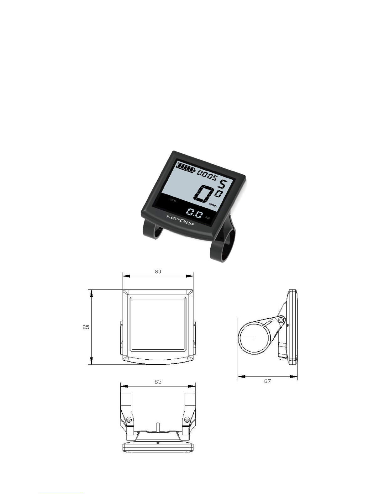
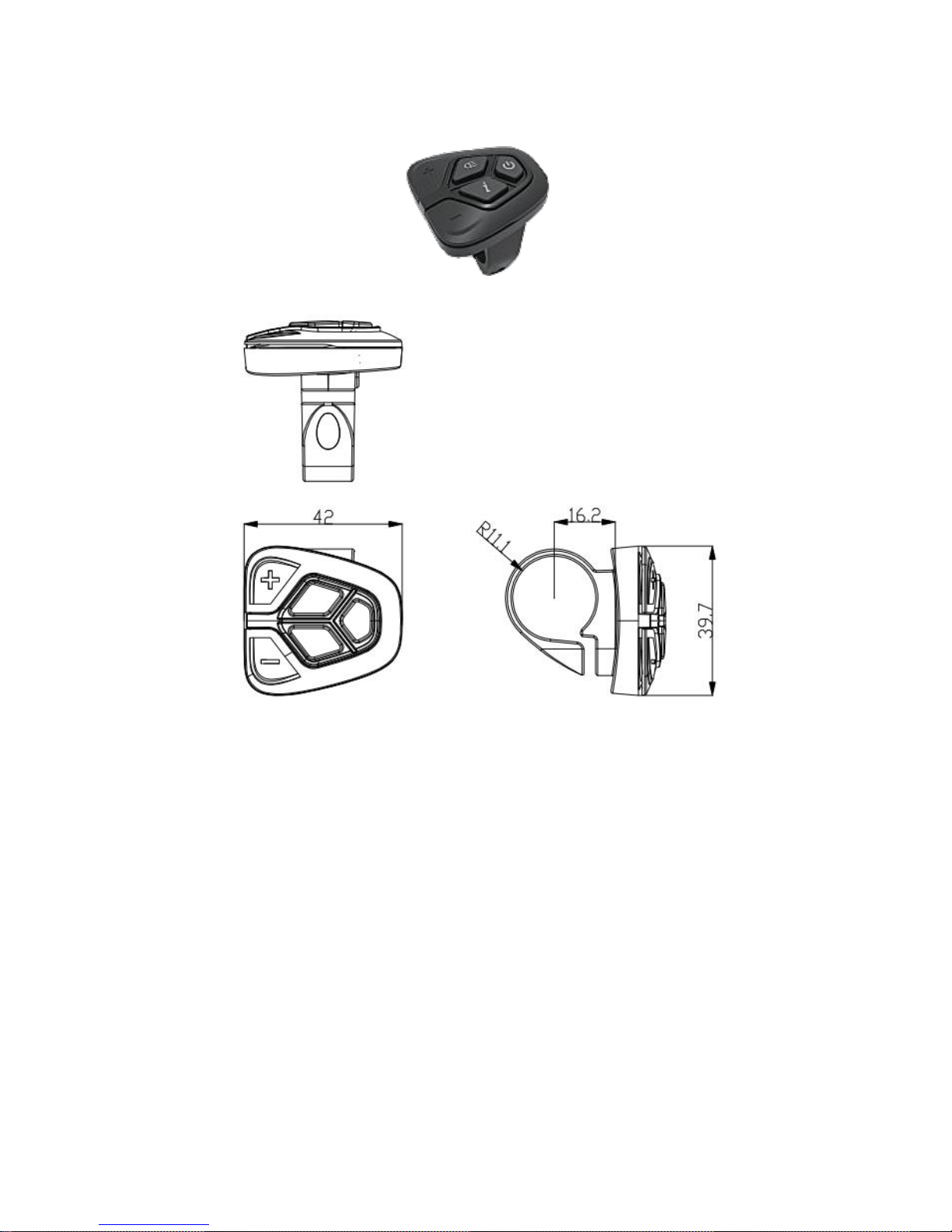
Appearance and Size
Display appearance and dimension figure (unit: mm)
2
Function Summary
◆Function Summary
KD51C-U can provide a lot of functions to fit the users’ needs. The indicating contents
are as following:
●Smart battery indicator
●Motor-output indicator
●Assistance-level indication
●Speed indication (incl. running speed, max speed and average speed)
●Odometer and trip distance
●The push-assistance function
●Trip time indication
●Time indication
●Backlight On/Off
●Error code indication
●USB port (optional)
●Pedaling frequency indication (optional)
●The remaining range indication (optional)
●Various parameters settings (e.g., wheel size, speed-limited, battery level bar,
assistance level, controller limited current, max speed, password enable, etc.)
●Recover default settings

3
◆Functional Area Distribution
Functional Area Distribution
General Operation
◆
Switching the E-bike System On/Off
Briefly press the power button to switch on the E-bike system, to hold the power button
for 2 s, the E-bike system will be switched off.
When switching off the E-bike system the leakage current is less than 1 uA.
■
When parking the E-bike for more than 10 minutes, the E-bike system switches off
automatically.
◆Display Interface
After switching on the E-bike system, the display will show Speed and Total Distance.
Pressing the “i” button will show more riding data as belows: Running Speed (Km/h)
→ Average Speed (Km/h) →Max Speed (Km/h) → Trip Distance (Km) → Total Distance
(Km) → Trip Time (Hour) .
USB Connection Indicator
Range /Time Unit
Speed Unit
Battery Indicator
Time Indication
Push-assistance Level Indication area
Function List
Text Indication
The Lighting Indicator
Power Indicator
Speed Indication

4
◆Switching Push-assistance Mode On/Off
To activate the push-assistance function, hold the “-” button always. The E-bike’s
drive is activated at a uniform speed of 6 Km/h.
The push-assistance function is switched off as soon as you release the “walk”
button on the operating unit.
Push-assistance Mode
■
Push-assistance function may only be used when pushing the E-bike. Danger of
injury when the wheels of the E-bike do not have ground contact while use the pushassistance function.
◆
Switching the Lighting On/Off
To switch on the lights (front light, rear light and display backlight), briefly press the
“ ” button. In the same way to press the “ ” button, the lighting can be switched off.
Switching the Lighting Mode On/Off
Interface
◆Assistance Level Selection
The level of assistance of the E-bike drive when pedaling can be adjusted via the
display. The assistance level can be changed anytime, even during riding.
The default assistance level ranges from level “0” to level “5”.The output power is zero on
Level “0”. Level “1” is the minimum power. Level “5” is the maximum power.
To increase the assistance level, press the “+” button until the desired assistance
level is displayed; to decrease the assistance level, press the “-” button. The default
value is level “1”.
Assistance Level “5”

5
◆Time Indication
The time can be displayed in the 24 hour format.
Time
Indication
◆Battery Indicator
The five battery bars represent the capacity of the battery. Each bar of the battery pack
symbol is equivalent to a capacity of approx. 20%. When the battery is in low voltage,
battery frame will flash to notice that the battery needs to be recharged immediately.
Battery Indicator
◆Motor Power Indicator
The power of the motor can be read via the interface.
Motor Power Indication
◆USB Connection Indicator (optional)
Charging of external device via the standard-USB port of the display. Using a matching
USB cable, connect the display via the standard-USB port to a smartphone or similar
devices. (5 V charging voltage; max. 1 A charging current).
USB Connection Indicator

6
◆Error Code Indication
The components of the E-bike system are continuously and automatically monitored.
When an error is detected, the respective error code is indicated in text indication area.
Here is the detail message of the error code in
Attached list 1
.
Error Code Indication
■
Make the display repaired when error code
appears.
General Settings
To access general settings menu, hold both the “+” button and the “-” button for 2 s.
■All the Settings are operated in the case of parking the E-bike.
◆Trip Distance Clearance
TC represents trip distance clearance setting.
To clear trip distance, press the “+” button or the “-” button until the Y is displayed.
To store a changed setting, press the “i” button and then access backlight contrast
settings.
Trip Distance Clearance Settings Interface
◆Backlight Contrast Settings
bL represents backlight contrast settings. Level “1” is the low brightness, Level “2” is
the middle brightness, Level “3” is high brightness. The default level is “1”.
To modify the backlight brightness, press the “+” button or the “-” button to
choose
the
desired setting item.
To store a changed setting, press the “i” button and then access the unit Conversion
Settings.
Backlight Brightness Settings Interface

7
◆Unit km/mi Conversion
U represents unit settings, “1” is mile and “2” is kilometer.
The default value is “2”.
To convert unit, press the “+” button or the “-” button
to choose
the desired setting item,
and then press the “i” button to confirm.
To store a changed setting, press
the “i”
button and then access trip distance clearance
settings.
To store a changed setting, hold
the “i”
button for 2 s and then exit general settings.
Mile and Kilometer Conversion Settings Interface
◆Time Settings
Hour represents time settings
, press
the “+” button or the “-” button
to choose the
options Y/N. The default value is N.
If you choose N, press
the “i”
button, and then access trip distance clearance settings.
If you choose Y, press
the “i”
button to enter Time settings, then use the same button
to shift the TIME, press the
“+” button or the “-” button
to change the number. To store a
changed setting, hold
the “i” button
for 2 s and then exit general settings.
Time Indication
General Parameter Settings
To access general parameter Settings interface, hold both the “+” and the “-” button for
2 s.
To access Wheel Diameter Settings, then hold both the “-” and the “i” button for 2 s
again.
◆Wheel Diameter Settings
Ld represents wheel diameter settings. Electable values include 16, 18, 20, 22, 24,
26, 700C and 28.
To change basic settings, press the “+” or the “-” button to increase or decrease until
the desired value is displayed.
To store a changed setting, press the “i” button. Then access the speed-limit settings
interface. The default value is 26 inch.

8
Wheel Diameter Settings Interface
◆
Speed-limit Settings
LS represents the limit speed settings. When the current speed is faster than speed
limit, the E-bike system will switch off automatically. Speed limit range is 12Km/h to 40Km/h.
The default value is 25Km/h.
To change basic settings, press the “+” or the “-” button to increase or decrease until
the desired value is displayed.
To store a changed setting and exit General Parameter Settings, hold the “i” button for
2 s.
Limit Speed Settings Interface
Personalized Parameter Settings
Personalized Parameter Settings can match variety requirements in use. There are 8
settings items, such as Battery Power Bar Settings, Power Assistant Level Settings, Overcurrent Cut Settings, Power Assistant Sensor Settings, Speed Sensor Settings, Throttle
Function Settings, System Settings and Power-on Password Settings.
To access Personalized Parameter Settings items option page, hold both the “+” and
the “-” button for 2 s, then hold both the “+” and the “-” button for 2 s again.
To access the corresponding settings page, press the “+” or the “-” button to increase
or decrease until the desired item is displayed, and then press the “i” button to confirm.
Options Selection Interface

9
◆Battery Power Bar Settings
VOL represents voltage settings. Each bar represents a voltage value. 5 bars voltage
values must be entered one by one.
For example, VOL 1 is first bar
voltage value. The
default value is 31.5V.
To set battery power bar, press the “+” or the “-” button to increase or decrease the
number.
To store a changed setting and access the second bar, press
the “i”
button.
By analogy, after 5
bars voltage values is entered
, hold
the “i” button
to confirm
and
then return to the previous menu.
Battery Power Bar Settings
◆
Assistance Level Settings (optional)
Assistance Level Option
In assistance level settings, there are 8 modes to select:0-3, 1-3, 0-5, 1-5, 0-7, 1-7, 09, 1-9. The default value is 0-5.
In assistance-level settings, there are 8 modes to select:0-3, 1-3, 0-5,
1-5, 0-7, 1-7, 0-9, 1-9. The default value is 0-5.
To change the mode of assistance-level, press the “+” or the “-” button to choose the
desired mode, and then press the “i” button to confirm, then access the PAS ratio settings
page automatically.
PAS Mode Option Interface
PAS Ratio Settings
To modify the value of PAS ratio, press the "+" button or "-" button to choose the
desired value, and then press the "i" button to confirm
For example, the range is “45-55 percent” of “1” level, bottom value can be modified,
and the default value is 50 percent.
To store the modified setting, press the “i” button and turn to the next PAS ratio settings.
After all PAS ratio inputted, hold the “i” button for 2 s to confirm and then return to
previous menu. Please refer to
Attached list 2.
10
PAS Ratio Interface
◆Controller Over-current Cut Settings (optional)
CUR represents controller over-current cut settings. CUR value can be changed from
7.0A to 25.0A. The default value is 15A.
To change basic settings, press the “+” or the “-” button to increase or decrease the
value of the current.
To store a changed setting, hold the “i” button and then return to previous menu.
CUR Settings Interface
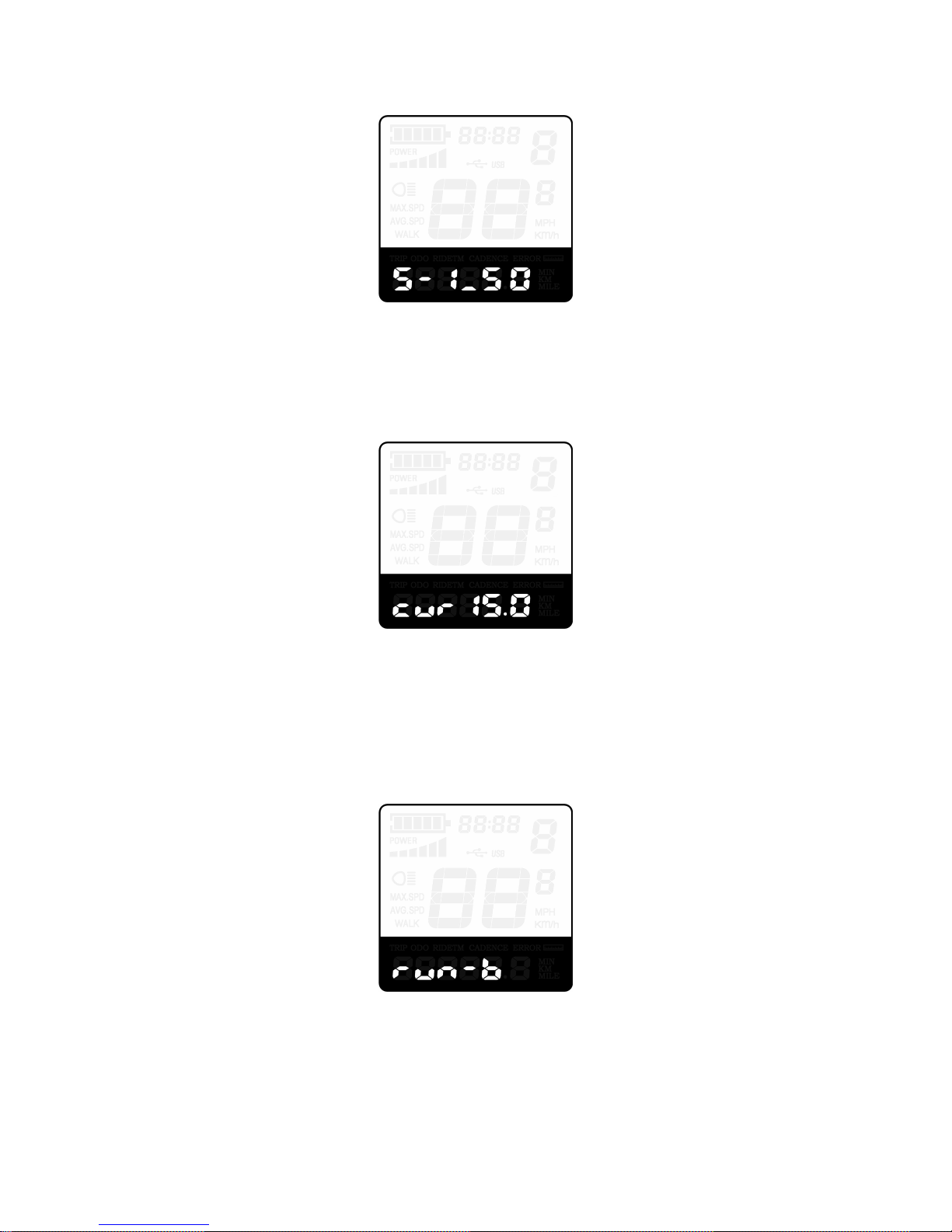
◆Power Assistant Sensor Settings (optional)
The Direction of PAS Settings
PAS represents power assistant sensor settings. “run-F” means forward direction,
while “run-b” means back direction. The default value is “run-F”.
To change The Direction of Power Assistant Sensor Settings, press the “+” or the “-”
button to select F or b.
To store a changed setting, press the “i” button and then access settings mode of PAS
sensitivity.
Direction of PAS Sensor Settings
The Sensitivity of PAS Settings
SCN represents the sensitivity of PAS settings. The sensitivity value is “2” to “9”. “2” is
the strongest, “9” is the weakest. The default value is “2”.
To change the sensitivity of PAS settings, press the “+” or the “-” button to select
sensitivity value.
To store a changed setting, press the “i” button and then access magnet disk settings
mode.

11
The Sensitivity of PAS Settings
Magnet Quantity Settings
n represents magnet numbers of PAS disk. The default value is 6.
To change magnet numbers of PAS disk, press the “+” or the “-” button to select
quantity corresponding to PAS disk.
To store a changed setting, hold the “i” button and then return to previous menu.
PAS Magnet Disk Settings
◆
Speed Sensor (optional)
SPS represents speed sensor settings. The default value is 1
To change speed sensor settings, press the “+” or the “-” button to select the quantity
of magnet head (the range is from 1 to 15).
To store a changed setting, hold the “i” button and then return to previous menu.
Speed Sensor Selection
◆
Throttle Definition (optional)
Throttle Push-assistance Enable/Disable
HL represents throttle push-assistance function. HL-N represents throttle assistance
push function is disabled. HL-y represents throttle assistance push function is enabled.
The default value is N.
To change throttle push-assistance function, press the “+” or the “-” button to select Y.
To store a changed setting, press the “i” button.
Otherwise, to select N and then access Throttle Level Enable Settings.

12
Throttle Enable/Disable Interface
Throttle Level Enable/Disable
HF-y represents throttle level enabled, HF-N represents throttle level is disabled. The
default value is N.
To change throttle level function, press the “+” or the “-” button to select Y or N and
then press the “i” button to confirm, then access Throttle Enable Settings page.
To return to previous menu, hold the “i” button for 2 s.
Throttle Level Enable or Disable Interface
◆System Settings (optional)
Delay Time Settings of Battery Power
dLY reresents delay time of battery power settings. The default value is 3 s.
To change delay time settings, press the “+” or the “-” button to select delay time 3 s,
6 s, 12 s.
To store a changed setting, press the “i” button and then access the max speed limited.
Delay Time of Battery Power Interface
Max Speed Limited
LS represents max speed limited settings. The default value is 40Km/h.
To change Max speed limited setting, press the “+” or the “-” button to set the max
speed from 25Km/h~40 Km/h.
To store a modified setting, press the “i” button and then access Button PAS Settings.

13
Interface of Max Speed Limited Settings
■This setting is the priority version. The speed is the maximum set by manufacturer.
Button Push-assistance Enable/Disable
PUS represents button push-assistance settings. Y represents button push is enabled,
N represents button push is disabled. The default value is Y.
To change button push-assistance settings, press the “+” or the “-” button to choose Y
or N.
To store a changed setting, press the “i” button and then access PAS speed settings.
Interface of Push-assistance
PAS Speed Settings
To change PAS speed settings, press the “+” or the “-” button to adjust from 20% to
35%.
To store a modified setting, press the “i” button and then access slowly start up.
The default value is 25%.
Interface of PAS Speed Settings
Slowly Start Up Settings
SSP represents slowly start up.The range is “1-4”, “4” is the slowest. The default value
is “1”.
To change slowly start up settings, press the “+” or the “-” button to select the desired
value.
To store a modified setting, press the “i” button and then turn to Delay time settings of
battery power page.To return to previous menu, hold the “i” button for 2 s.

14
Interface of Slowly Settings Up
◆
Power-on Password Settings
P2, 0000 on the screen means power-on password settings. The password is 1212.
To access the power-on password settings, press the “+” or the “-” button to modify
the value and then press the “i” button to confirm digit one by one until the correct 4-digit
password is completed, and then press the “i” button to access power-on password enable
settings interface, otherwise stay on the password input state.
Power-on Password Entering Interface
Power-on Password Enable/Disable
To change power-on password enable/disable settings, press the “+” or the “-” button
to select Y or N.
If it is Y, press the “i” button and then access power-on password modify interface,
otherwise exit the power-on password settings interface. The default value is N.
Y is power-on password enable.
N is power-on password disable.
Power-on Password Disable Interface
Power-on Password Modify
When the display shows P3, 0000, to set new power-on password, press the “+” or
the “-” button to modify the value and then press the “i” button to confirm digit one by one
until the new 4-digit password is completed.
To store the new power-on password, hold the “i” button for 2 s and then exit settings.
When switching the E-bike system on next time, the display will show P1,0000, please
input the new password to power on.

15
Power-on Password Modify Interface
◆
Exit Settings
In the settings state, press the “i” button is to confirm the input. Hold the “i” button is
to store the settings, and then exit the current settings. Hold the “-” button is to cancel the
operating but not storing settings data, and then return to previous menu.
■
If there is not any operations in one minute, the display will exit the settings state.
Recover Default Settings
dEF represents recover default settings.
The default value is N.
To access recover default settings, hold both the “+” and the “i” button for 2 s.
Press the “+” or the “-” button to choose Y or N again. N means that do not recover
default settings. Y means that recovers default settings.
When it is Y, hold the “i” button for 2 s to recover default settings; the display shows
DEF-00 at the same time, and then return to general display state.
Recover Default Settings Interface
Quality Assurance and Warranty Scope
Ⅰ Warranty
1) The warranty will be valid only for products used in normal usage and conditions.
2) The warranty is valid for 24 months after the shipment or delivery to the customer.
Ⅱ Others
The following items do not belong to our warranty scope.
1) The display is demolished.
2) The damage of the display is caused by wrong installation or operation.
3) Shell of the display is broken when the display is out of the factory.
4) Wire of the display is broken.
5) Beyond Warranty period.
6) The fault or damage of the display is caused by the force majeure (e.g. fire,
earthquake, etc.).

16
Connection Layout
Connector line sequence
Display-side Connector Display-side adapter Switch
wiring
Line sequence
table
Line
Color
Function
1
Red(VCC)
+
2
Blue(K)
Lock
3
Black(GND)
-
4
Green(RX)
RX
5
Yellow(TX)
TX
■Some wire use the water-proof connector, users
can not see the inside color.
Operation Cautions
Be careful of safe use. Don’t attempt to release the connector when battery is on
power.
● Try to avoid hitting.
● Do not modify system parameters to avoid parameters disorder.
● Make the display repaired when error code appears.
Attached list 1:Error code definition
Error
Code
Definition
21
Current Abnormality
22
Throttle Abnormality
23
Motor Abnormality
24
Motor Hall Signal Abnormality
25
Brake Abnormality
30
Communication Abnormality

17
Attached list 2:Power assist table
Level
Level selection
123456789
0-3/1-3
50%
74%
92%
—————
—
0-5/ 1-5
50%
61%
73%
85%
96%
———
—
0-7/ 1-7
40%
50%
60%
70%
80%
90%
96%
—
—
0-9/ 1-9
25%
34%
43%
52%
61%
70%
79%
88%
96%
 Loading...