

Key Digital KD-Pro8x8D, KD-X88LGR series, KD-X88SHR series Operating Instructions Manual
8x8 HDBaseT/HDMI/POH Matrix Switcher, Integrated
Audio, DSP/De-embedding of Analog L/R Balanced/
Unbalanced, Digital Coaxial Audio, ARC
(Includes 8 Rx Extenders- 6 Short & 2 Long Range)
KD-Pro8x8D
Operating Instructions
The Experts in Digital Video Technology and Solutions
™
x2
x6
KD-X88LGRx KD-X88SHRx

4
Always follow the instructions provided in this Operating Manual.
Table of Contents
Introduction ................................................................ 4
About KD-X88SHRx and KD-X88LGRx HDBaseT receive extenders ..................... 2
Connections, Buttons and LEDs ................................................ 3
KD-X88SHRx and KD-X88LGRx LED Indicator Lights ................................ 6
Application Example ......................................................... 7
Quick Setup Guide .......................................................... 8
Settings and Adjustments via Remote ............................................ 8
KD-X88LGRx Control Rotary .................................................. 11
Audio Return Channel (ARC) .................................................. 13
IR & RS-232 Control Routing Ports and Uses ..................................... 14
RS-232 and TCP/IP Commands . . . . . . . . . . . . . . . . . . . . . . . . . . . . . . . . . . . . . . . . . . . . . . . 19
Using KD-Pro8x8D in a Compass Control® Pro project.............................. 25
Specifications ............................................................. 27
Important Product Warnings & Safety Instructions: ................................. 28
How to Contact Key Digital ................................................... 29
Warranty Information ........................................................ 29
Introduction
Key Digital® KD-Pro8x8D is a UHD/4K, HDCP 2.2, and ARC supporting digital video matrix
with audio de-embedding on analog and digital audio connectors. Video outputs feature
simultaneously active HDMI and HDBaseT ports for simplistic single-wire integration with
displays throughout the distributed video system. Six short range (model KD-X88SHRx)
and two long range extenders (model KD-X88LGRx) deliver UHD/4K video up to 125 ft. and
300 ft. respectively and are powered at the matrix switch. IR and RS-232 control routing
adds up to 34 control ports to third-party control systems.

1
Key Features
› Ultra HD/4K:
Supports signals up to 4096x2160 60Hz [4:2:0] 8bit or 4096x2160 30Hz [4:4:4] 8bit
› Bandwidth: 10.2Gbps supports UHD/4K resolutions with HDR via EDID handshaking
› HDR (High Dynamic Range): More life-like images through a greater range of luminance levels
› HDCP 2.2 and HDMI Licensing: Fully licensed and compatible with HDCP 2.2 and HDMI latest
technologies
› Simultaneously Active: 8 HDBaseT (CAT5e/6 RJ45) and 8 HDMI outputs with fully automatic
CAT5e/6 cable equalization. Supports up to 16 displays (8 mirrored)
› HDBaseT Rx Included: 8 total Rx extenders integrate with built-in HDBaseT Tx output ports
» Six (6) Standard Range KD-X88SHRx
» Two (2) Long Range KD-X88LGRx
› Signal Extension:
» KD-X88SHRx:
» Up to 200 feet @ 1080p/60, 1080p/24, 1080i, 720p
» Up to 125 feet @ 4K/Ultra HD
» KD-X88LGRx:
» Up to 328 feet @ 1080p/60 (Standard Range Mode)
» Up to 328 feet @ 4K/Ultra HD
› Audio Return Channel: Audio may be returned from display to respective audio output
› Audio De-Embedding: Audio from the selected HDMI input may be de-embedded through the
Coax digital (PCM) and analog L/R balanced/unbalanced output
› Audio DSP: Variable level settings for volume, muting, 3-band EQ, balance, and lip-sync delay
per output
› Long Range Mode: Outputs 1 and 5 extend 1080p signals up to 500 ft. (152m) using CAT5e/6
› Full Buffer
™
Technology: Full buffering of HDCP and EDID, for the fastest possible switching and
viewing of any source/input to any display/output, regardless of multiple output viewing relation
› EDID Control: Internal library with 15 default EDID configurations for each input, in addition to
native EDID data for any Output/Display
› TMDS Re-clocking: Support for long HDBaseT and HDMI runs and many layers of connectivity.
› Voltage Control: Two dedicated 3-pin relays and any control I/O ports may be used as a voltage
trigger
› Lossless Compressed Digital Audio: Dolby
®
TrueHD, Dolby® Digital Plus, Dolby® Atmos and
DTS-HD Master Audio
™
› Deep Color Support: Up to 12 bits/color
› Control Routing: Enables bi-directional IR/RS-232 control signal extension
adding 36 ports to control system
› Control Integration: TCP/IP, RS-232, and USB with full bi-directional operation, front panel push
buttons and LEDs, front/rear optical IR, serial IR,
› Control System Support: Key Digital
®
App ready, Compass Control® Pro ready, KD-Wizard®
ready. Fully controllable by all IR, RS-232, and TCP/IP supported control systems via open API:
AMX
®
, Crestron®, Control4®, KNX®, RTI®, Savant, URC®, Leviton® etc.
› Key Digital
®
App Ready: Scan & detect population for pre-built GUI and TCP/IP control via Key
Digital
®
App

2
Accessories
› 6 standard range receiver extenders, model KD-X88SHRx
› 2 long range receiver extenders, model KD-X88LGRx
› 2 external power supplies +12V/6.6A (80W) for powering of matrix and POH Rx units, model
› IR Remote control, model KD-REMOTEHM88
› 6 ft. USB A to Micro USB data cable
› 8 IR emitters
› Rack mount ears
Rack Mounting
› Secure the included rack ears to each side of KD-Pro8x8D with the supplied hardware, then
fasten the unit to the rack rails with appropriate machine screw.
About KD-X88SHRx and KD-X88LGRx
HDBaseT receive extenders
› Extends HDMI video + audio, and control (IR and RS-232) via a single CAT5e/6 UTP or STP cable
› Powered at the matrix. No local power connections needed.
› KD-X88SHRx:
» Up to 200 feet @ 1080p/60, 1080p/24, 1080i, 720p
» Up to 125 feet @ 4K/Ultra HD
› KD-X88LGRx:
» Up to 500 feet @ 1080p/60 (Long Range Mode)
» Up to 328 feet @ 1080p/60 (Standard Range Mode)
» Up to 328 feet @ 4K/Ultra HD
› Long Range Mode:
» If set to for Outputs 1 or 5, 1080p/60 signals are extended up to 500 ft. (152m). UHD/4K is
not supported if Long Range Mode is enabled
» Must be set in unit via IR or control software
» Must be set on desired KD-X88LGRx unit via Control Rotary
› Installation best practices:
» Use the shortest possible HDMI cable when connecting KD-X88SHRx / KD-X88LGRx to a
display. HDMI cables ≤ 9ft recommended for optimum performance.
» Ensure the CAT5e/6 cable runs directly from the switcher to the KD-X88SHRx / KD-
X88LGRx.
» Do not use patch panels, punch downs, keystones, couplers, wall plates, etc.
» Use shielded twisted pair (STP) cabling with shielded RJ45 connectors for optimum
performance and distances.
3
Connections, Buttons and LEDs
HDMI & HDBaseT
› HDMI Inputs (8): Located on the left side of the back panel. The inputs have a blue LED that
illuminates when a source is connected and synced
› HDMI & HDBaseT Outputs (8 each): Located in the middle of the back panel. The HDMI and
HDBaseT outputs each have a blue LED that illuminates when an output device is connected
and synced
» HDBaseT outputs 1 and 5 integrate natively with long range extenders, model KD-XLGRx
» HDBaseT outputs 2, 3, 4, 6, 7, 8 integrate natively with short range extenders,
model KD-XSHRx
Audio De-Embed Outputs
› Each Output features audio de-embedding on (1) Analog L/R balanced/unbalanced 6-Pin
terminal and (1) Digital audio on RCA
› The audio de-embed ports provide audio output of the selected HDMI input for the respective
output (default) or returned audio (ARC) from the connected display if enabled. See Audio Return
Channel (ARC) section for more information
› The analog audio de-embed ports feature an assortment of DSP controls including Volume,
Muting, 3-band EQ, and Lip-sync delay. The digital audio outputs feature muting control only.
› There are no down/up conversion capabilities. For example, in order to achieve 2ch analog audio
output, the selected HDMI input source audio format must be 2ch.
› Pin assignment for Analog Audio outputs:
» Left + is Pin 1; Left Ground is Pin 2; Left - is Pin 3
» Right + is Pin 4; Right Ground is Pin 5; Right - is Pin 6
Audio Input
Signal Format
Audio L/R
Output
Digital Audio
Output
2CH PCM Pass-through Pass-through
Multi-Channel PCM MUTE MUTE
DOLBY/DTS MUTE Pass-through
HD Audio MUTE MUTE

4
Unit Control Ports
› MAIN Control Port
» 6-Pin Terminal Block for IR and RS-232
» RS-232 and TCP/IP commands may be found in the RS-232 & TCP/IP Commands section
» Pin out:
» Pin 1 = IR Signal
» Pin 2 = IR Ground
» Pin 3 = RS-232 Tx Data
» Pin 4 = RS-232 Ground
» Ping 5 = RS-232Rx Data
» Pin 6 = Ground (optional)
› TCP/IP Control Port
» Connect an Ethernet cable from the KD-Pro8x8D to a network router or connect a straight-
through cable directly from a PC
» Default IP address is 192.168.1.239, with default port 23
› Firmware Mode Switch
» Should remain in Operation setting unless instructed by Key Digital technical support
» If changing position of switch, do so only with matrix unit not powered
» Not every firmware update requires the switch to be set to the F/W Load position
» If set to F/W Load, all front LEDs will be illuminated, indicating that unit is in bootloader
mode and awaiting a firmware load.
› Micro USB (front panel)
» Typically used for unit configuration, control, and firmware updates
» It is most commonly used with KD-Wizard
®
software downloaded at www.keydigital.com

5
Control I/O Ports
› 8 multifunction I/O ports that can be used as IR, bi-directional RS-232 or voltage trigger
» Pin out:
» Pin 1 = RS-232 TxD / IR Signal
» Pin 2 = Ground
» Pin 3 = RS-232 RxD / IR No Connect
› 1 dedicated IR and RS-232 port
» Used as primary IR/RS-232 input source for Control Routing
» RS-232 and TCP/IP commands may be found in the RS-232 & TCP/IP Commands section
» Pin out:
» Pin 1 = IR Signal
» Pin 2 = IR Ground
» Pin 3 = RS-232 Tx Data
» Pin 4 = RS-232 Ground
» Ping 5 = Rs-232Rx Data
» Pin 6 = Ground (optional)
› 2 Relay ports
» Electrically operated switch with 250VAC/12A (2500W) Resistive switching capacity
» COM-NC (normally closed) is connected when relay is activate
» COM-NO (normally open) is connected when relay is inactivate

6
Buttons and LEDs
› 8 output buttons on the front panel
» Pressing an output button will select the next HDMI input
» A blue LED indicates selected input for each output
› Video output MUTE is indicated by the outermost (1, 2, 7, 8) LEDs illuminated,
while the inner LEDs (3, 4, 5, 6) are NOT illuminated
› Video output OFF is indicated when the innermost (3, 4, 5, 6) LEDs are illuminated,
while the outermost (1, 2, 7, 8) are NOT illuminated
› Factory default reset is achieved by simultaneously holding the input select buttons 1&4 for 10
seconds
» The matrix reboots after reset. The LEDs will ramp until reboot has completed
KD-X88SHRx and KD-X88LGRx LED Indicator Lights
KD-X88LGRx KD-X88SHRx
› Power:
Green
» Solid illumination during power ON state, as provided by POH power supply at matrix switch
› HDMI Active:
Blue
» Solid illumination from active Hot Plug Detection voltage with connected display/output
device
› HDBaseT Link:
Blue
» Solid illumination from active HDBaseT link with matrix switch
7
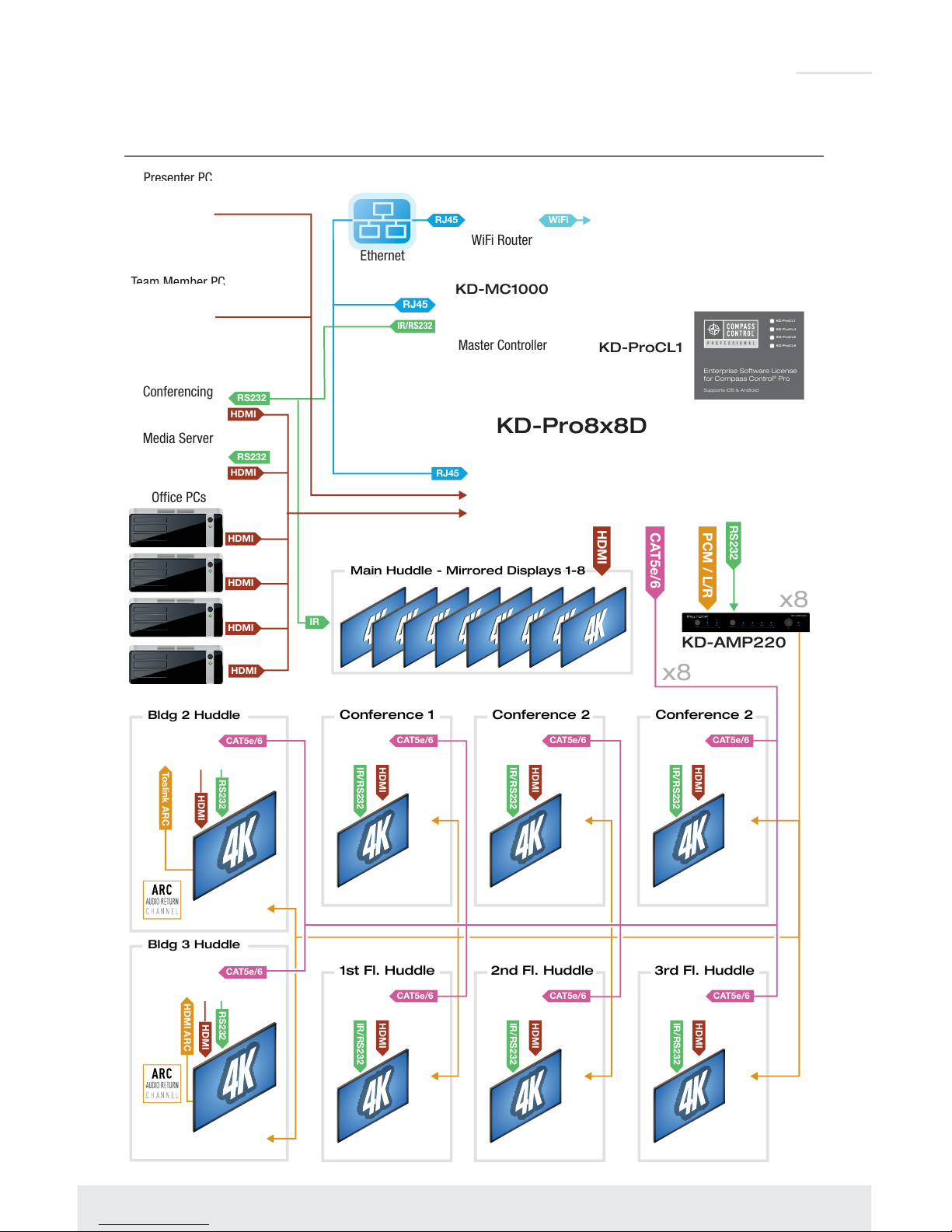
Application Example
Office PCs
Media Server
Conferencing
Presenter PC
Team Member PC
3rd Fl. Huddle2nd Fl. Huddle1st Fl. Huddle
Bldg 3 Huddle
Conference 2 Conference 2Conference 1Bldg 2 Huddle
CAT5e/6
HDMI
IR/RS232
CAT5e/6
HDMI
IR/RS232
CAT5e/6
HDMI
IR/RS232
CAT5e/6
HDMI
IR/RS232
CAT5e/6
HDMI
IR/RS232
CAT5e/6
HDMI
IR/RS232
WiFi Router
CAT5e/6
Ethernet
KD-Pro8x8D
x8
HDMI
HDMI
HDMI
RS232
RS232
RS232
IR/RS232
Main Huddle - Mirrored Displays 1-8
HDMI
RJ45
WiFi
RJ45
HDMI
IR
Enterprise Software License
for Compass Control
®
Pro
Supports iOS & Android
KD-ProCL8
KD-ProCL6
KD-ProCL4
KD-ProCL1
HDMI
HDMI
RJ45
KD-MC1000
KD-ProCL1
Master Controller
x8
KD-AMP220
Input Control
Vol
Mic
Mute
Line BassL/R PCM
1
2
Treble
KD-AMP220
PCM / L/R
HDMI
RS232
Toslink ARC
HDMI
RS232
HDMI ARC
CAT5e/6
CAT5e/6

8
Quick Setup Guide
1. Begin with the KD-Pro8x8D and all input/output devices turned off and power cables removed
2. Connect HDMI sources to the desired input ports on the KD-Pro8x8D
3. Connect HDBaseT outputs to the Rx extenders via CAT5e/6 cables
4. Connect HDMI output of Rx extenders to the output devices (display, projector, AV Receiver,
etc)
5. Connect HDMI outputs to the appropriate output device (output signals mirror HDBaseT
outputs)
6. Connect both power supplies (one for matrix and one for the POH Rx extenders) to the KD-
Pro8x8D and all other input and output devices and power them on
7. Operate the KD-Pro8x8D switcher via front panel buttons, IR Remote, Serial IR or RS-232
control. See Setting and Adjustments via Remote section for quick adjustments during initial
installation
8. If TCP/IP control is desired, set the IP address using appropriate Key Digital software from
www.keydigital.com. Note that many advanced commands are available only via TCP/IP and
RS-232 protocol
Settings and Adjustments via Remote
Many initial installation steps may be configured using the factory remote control. Other advanced
settings may be configured using USB and software downloaded from www.keydigital.com
Matrix Switching Command via IR
IR Button Sequence = Video Mode, X, Y
» X = Output # [1-8]
» Y = Input # [1-8]
EDID Handshaking Control
EDID (Extended Display Identification Data) is a data structure provided by a digital display to
describe its capabilities to a video source. This data is also known as a “handshake” and typically
includes manufacturer, serial number, product type, resolutions supported by the display, display
size, pixel mapping data, etc.
Key Digital EDID Control allows the integrator to choose the handshake that will be provided to
each HDMI source. The integrator may select from the following EDID file options:
» Default EDID Library: The EDID handshake is relayed to the source from the matrix
switcher’s default EDID table (see table below)
» Copy from connected HDMI or CAT5e/6 (HDBaseT) output: The EDID file of a selected
output device is copied to the software of the matrix switcher and relayed to the source.
This is sometimes necessary if working with very new or very old displays.
› EDID Setup Command via IR
» XX = Input # [01-08]
» YY = Output # [01-08]
» ZZ = Default EDID Table File [01-15]
 Loading...