

Key Digital KD-VW4x4Pro Operating Instructions Manual
Rev 0 – Apr 2016
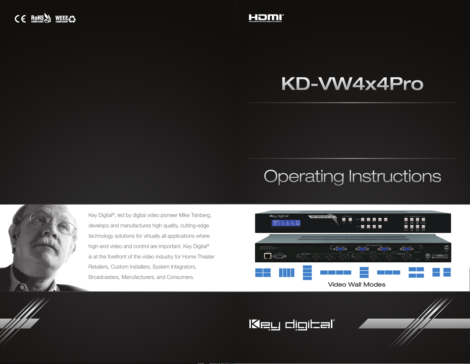
KD-VW4x4Pro
4 Inputs to 4 Outputs
Video Wall Processor,
supports Seamless Matrix Switching
Operating Instructions
Key Digital®, led by digital video pioneer Mike Tsinberg,
develops and manufactures high quality, cutting-edge
technology solutions for virtually all applications where
high-end video and control are important. Key Digital
is at the forefront of the video industry for Home Theater
Retailers, Custom Installers, System Integrators,
Broadcasters, Manufacturers, and Consumers.
Key Digital® Systems :: 521 East 3rd Street :: Mount Vernon, NY 10553
Phone : 914.667.9700 Fax : 914.668.8666 Web : www.keydigital.com
®
The Experts in Digital Video Technology and Solutions
™
4 1
Table of Contents
About KD-VW4x4Pro......................................................... 1
Quick Setup Guide .......................................................... 2
Application Example ......................................................... 3
Connections, Buttons and LEDs ................................................ 4
IR Remote Control........................................................... 8
Video Wall Modes .......................................................... 10
RS-232 & TCP/IP Commands ................................................. 18
Bezel Control for Video Wall Mode.............................................. 21
Specifications ............................................................. 23
Important Product Warnings & Safety Instructions: ................................. 24
How to Contact Key Digital ................................................... 25
Warranty Information ........................................................25
About KD-VW4x4Pro
Key Digital’s Video Wall Series, KD-VW4x4Pro, enables you to turn standard consumer or
professional displays into a video wall. This video wall processor features eight different video wall
modes including many horizontal and vertical layouts in addition to 2x2. KD-VW4x4Pro supports
seamless 4x4 matrix switching, and analog to digital conversion of incoming VGA with analog
audio signals.
KD-VW4x4Pro is designed to fit a wide variety of professional video installation and live-event
needs. It is ideal for retail digital signage, conference & board room, bar/restaurant, house of
worship, corporate A/V, data monitoring centers, and more.
Key Features
› HDMI Matrix Switching:
matrix mode
› Seamless Switching:
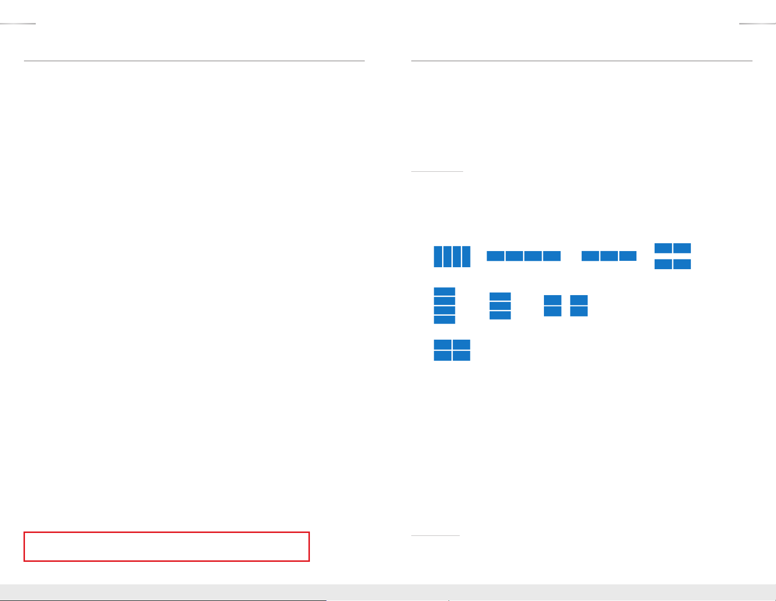
› Video Wall Processing:
eight video wall modes
» Horizontal (4): 1x4 Rotated, 1x4, 1x3, and two sets of 1x2
» Vertical (3): 4x1, 3x1, and two sets of 2x1
» 2x2
4 HDMI/Analog sources to 4 HDMI outputs, independent when in
Un-interrupted screen transitions during source selections
Transform consumer and professional displays into a video wall with
Always follow the instructions provided in this Operating Manual.
Please check the Key Digital Website for the most up-to-date Manual.
© 2016 Key Digital, Inc. All rights reserved.
› Bezel Control:
Create a fluid screen transition by removing pixels from top, bottom, left, and
right border independently
› EDID:
Internal library with 5 default EDID configurations for each input, in addition to native EDID
data for any Output/Display
› Full Buffer
™
Technology
: Full buffering of HDCP and EDID, for the fastest possible switching
and viewing of any source/input to any display/output, regardless of multiple output viewing
relation
› TMDS re-clocking
: Support for long HDBaseT/CAT5e/6 or HDMI connections
and many layers of connectivity.
› Deep Color Support:
› Control:
Front panel buttons, Serial IR, Optical IR, RS-232, and TCP-IP, including video wall
Up to 12 bits/color
mode select, matrix switching, EDID Control and discrete on and off via IR
› Control System Support: Compatible with Compass Control
®
KNX
, RTI®, Savant, URC®, Leviton®, etc.
®
, AMX®, Control4®, Crestron®,
Accessories
› Power supply: KD-PS12V3ASC, 12V/3A, Screw-in type
› IR Remote control: KD-RMVW4x4
› Rack Ears
2 3
Rack Mounting:
› Secure the rack ears to each side of the
KD-VW4x4Pro
with the supplied hardware, then fasten
the unit to the rack rails with the included machine screws.
Quick Setup Guide
1. Begin with the KD-VW4x4Pro and all input/output devices turned off and power
cables removed.
2. Connect HDMI and/or Analog Video and Audio Sources to the desired KD-VW4x4Pro
input ports.
3. Connect display devices to the HDMI outputs.
4. Connect power to the KD-VW4x4Pro and power on, then repeat for source devices, then
display devices.
5. Choose desired mode via front panel buttons, IR, RS-232 or TCP-IP.
» a. Please refer to following sections for more information on controllability and setup for
each control type.
IR Emitter Control
When using an IR Emitter / IR Extender (sold separately), the IR Emitter must be mounted over
the IR Sensor on the front of the KD-VW4x4Pro. One end of the cable is connected to the IR
Receiver/ Master Controller / IR Extender / IR Connecting Block, while the other end is mounted
over the IR Sensor of the KD-VW4x4Pro
Serial IR Control
As a more robust alternative to optical IR, KD-VW4x4Pro may also be controlled via hard-wired IR.
Use a 3.5mm Male Mono plug with the IR Signal carried on the tip of the connector.
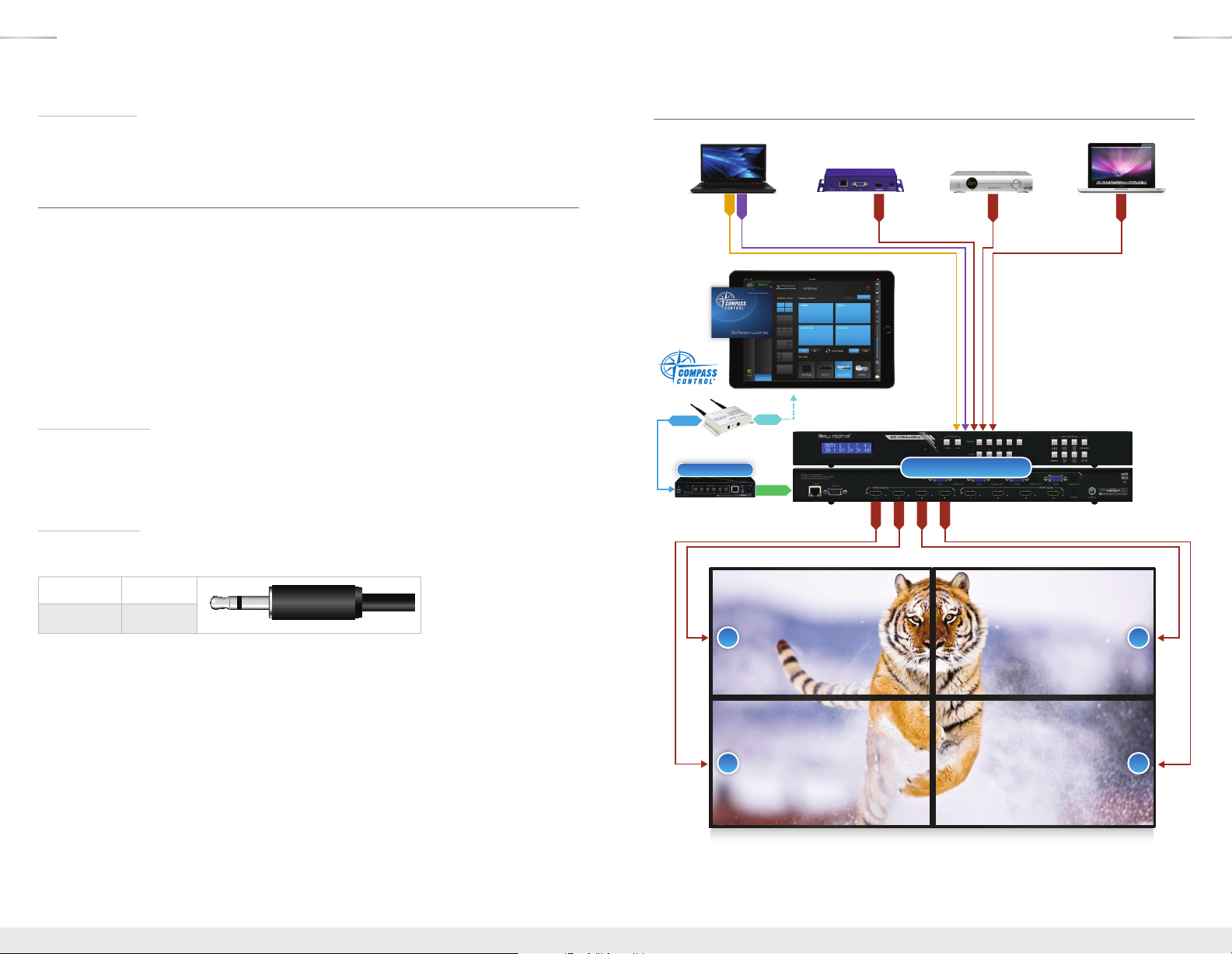
Application Example
VGA Laptop
Signage
VGA
L/R
RJ45
KD-MC1000
Master Controller
WiFi
Router
RS-232
Digital
HDMI
iPad
KD-VW4x4Pro
HDMI
HDMI
HDMI
Cable/Satellite
HDMI
HDMI
HDMI Laptop
HDMI
Tip Ring
TX or RX None
1 2
3 4
4 5
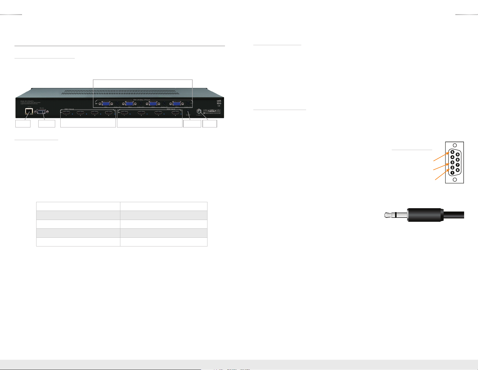
Connections, Buttons and LEDs
Rear Panel Connections:
All connections to the KD-VW4x4Pro are found on the rear panel of the unit. Refer to the
illustrations below for port assignments while making connections.
VGA/DB15 & Analog L/R Inputs
HDMI InputsHDMI Outputs
Input Connections
Located on the right side (HDMI) and top center (VGA/Analog L/R) of the back panel
› HDMI Inputs (4 Total)
» Compatible with HDMI 1.4a and HDCP 1.x standards
» Active link (voltage + data) with connected source indicated by illuminated LED
» Does not support CEC
» Does not support incoming audio formats greater than 2-channel.
» The connection is automatically muted if the selected audio source format is not
2-channel PCM.
Audio Format from Input Source Coaxial Digital Audio Output
2CH PCM Pass-through
Multi-Channel PCM
DOLBY/DTS
HD Audio
› VGA / DB15 Inputs (4 total)
» VGA / DB15 supported input resolutions:
» 640x480@60/75, 800x600@56/60/75, 1024x768@60/75, 1280x768@60/75,
MUTE
MUTE
MUTE
1366x768@60/75, 1280x1024@60/75, 1440x900@60/75, 1600x900@60,
1600x1200@60, 1920x1080@60, 1920x1200@60
› Analog L/R Inputs (4 total)
» 3.5mm stereo connector
» Associated with VGA input only
» Sampling frequency = 48KHz, 24Bits
» 2 VRMS Line Audio L/R input signal
Serial IRTCP/IP RS-232 Power
Output Connections
Located on the right side of the back panel.
› HDMI Outputs (4 Total)
» Compatible with HDMI 1.3b standard
» Output resolution is fixed to 1080p@60 fps
» Supports 2-channel audio only
» Does not support DVI video format / connections
» Active link (voltage + data) with connected output indicated by illuminated LED
Control & Power Ports
Located on the left-most (RS-232, and TCP-IP) and right-most (power and serial IR) sides of the
back panel.
› The RS-232 port is used for control, as well as firmware updates
» Refer to RS-232 Commands and Protocol section for complete code-set
›
The RS-232 baud rate is 57,600
› The RS-232 port is a Female connection,
and is straight-thru
» Pin 2 = Tx
» Pin 3 = Rx
» Pin 5 = Ground
› The TCP-IP port is used for control, as well as firmware updates
» Refer to RS-232 and TCP-IP Commands and Protocol section for complete code-set
› The Serial IR port is a 3.5mm Mono connector for hard-wired IR signals
» Tip = IR Signal
» Ring = Ground
› The Power port is a screw-type connection.
» Thread power connection to KD-VW4x4pro unit before connecting to power outlet
RS-232 cable pin out
Pin 5 – Ground
Pin 3 – Receive
Pin 2 – Transmit
6 7
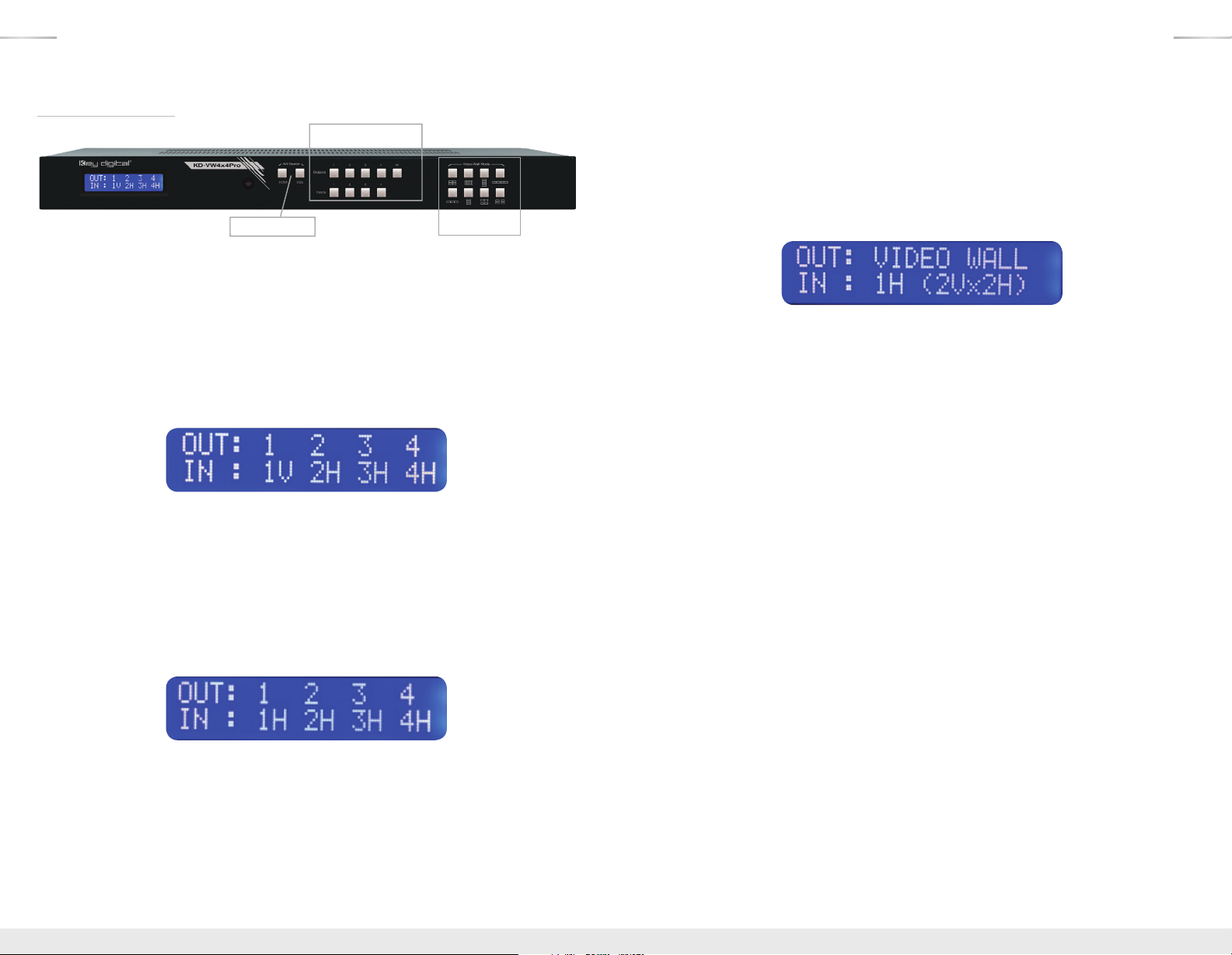
Front Panel Operation
Matrix Mode Switching
HDMI/VGA Select
Video Wall Mode
The front-panel of KD-VW4x4Pro features 3 sets of buttons:
› HDMI / VGA input-type select (2 buttons)
» Enables selection of the HDMI digital video input or VGA analog video input for the specified
source
»
To select HDMI or VGA input type:
» 1. Press the desired Input 1, 2 , 3, or 4 (video source)
» 2. Press either HDMI or VGA, as desired, to lock in the setting
» 3. Confirmation example: V is for VGA, H would be present for HDMI
› Matrix Mode Switching select (2 rows of 4 buttons, plus All button)
» Enables selection of any input source (1-4) for the selected output, or to select a single
source to be viewed on all outputs
»
To configure matrix switching:
» 1. Choose the desired output you would like to control, or All,
using the Output 1, 2, 3, 4, or All buttons
» 2. Choose the desired Input 1, 2 , 3, or 4 (video source) you would like to view
on the selected output (or all outputs)
» 3. Confirmation example:
› Video Wall Mode Select: (2 rows of four buttons)
» Enables the selected source to be displayed across all outputs in the desired layout
»
To select video wall mode:
» 1. Choose the desired video wall layout
» 2. Choose the desired Input 1, 2 , 3, or 4 (video source) you would like to
view for that layout
» 3. Confirmation example::
» When 1Vx3H and 3Vx1H video wall modes have been selected,
video muting is applied to output 4
» When 1Vx2H and 2Vx1H modes have been selected, there are two sets available:
Outputs 1 + 2, and Outputs 3 + 4
› Factory Default Reset via the Front panel
» To reset the unit to Factory Default settings, simultaneously press and hold the HDMI Input-
Type Select button and Video Wall Mode 1 (2Vx2H) button for approximately 10 seconds
» Default Settings:
» Unit Address is 00
» Unit is set to Matrix mode
» Output 1 is set to Input 1, 2 with 2, 3 with 3, 4 with 4
» EDID to all inputs is Default 2 (1080p, 2ch audio)
» All other internal parameters set to default
» When in matrix mode, the chosen output and the current source is indicated by a blue fill of
the respective Output and Input buttons
» If a Video Wall Mode is chosen, the Input being viewed by the outputs is illuminated
» Matrix Output Select buttons are not illuminated when in video wall mode
 Loading...