

Page 1
The Experts in Digital Video Technology and Solutions.
The Experts in Digital Video Technology and Solutions.
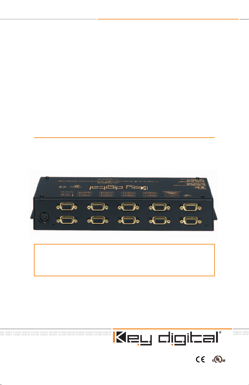
Model KD-RGBDA8
HD View 8
8-channel VGA Distribution Amplifier
OPERATING INSTRUCTIONS
TM
The HD View 8TMis an 8-channel VGA Distribution Amplifier. It is the logical
choice for artifact-free distribution of your VGA signals. If you have VGA
(RGBHV) signals from any HDTV multimedia or computer source you can
feed up to eight or more VGA monitors.
Page 2

The Experts in Digital Video Technology and Solutions.
The Experts in Digital Video Technology and Solutions.
Page 2 of 8
HD View 8TMOperating Instructions
HD View 8TM/ Model KD-RGBDA8
Safety Instructions – Please be sure to follow these
instructions for safe operation of your unit
1
Read these instructions.
2
Keep these instructions.
3
Heed all warnings.
4
Follow all instructions.
5
Do not use this apparatus near water
6
Clean only with dry cloth.
7
Do not block any ventilation openings. Install in accordance with the manufacturer’s
instructions.
8
Do not install near any heat sources such as radiators, heat registers, stoves, or other
apparatus (including amplifiers) that produce heat.
9
Do not defeat the safety purpose of the polarized or grounding-type plug. A polarized
plug has two blades with one wider than the other. A grounding type plug has two
blades and a third grounding prong. The wide blade or the third prong are provided
for your safety. If the provided plug does not fit into your outlet, consult an electrician
for replacement of the obsolete outlet.
10
Protect the power cord from being walked on or pinched particularly at plugs, convenience receptacles, and the point where they exit from the apparatus.
11 Only use attachments/accessories specified by the manufacturer
Use only with the cart, stand, tripod, bracket, or table specified by the manufacturer, or
12
sold with the apparatus. When a cart is used, use caution when moving the
cart/apparatus combination to avoid injury from tip-over.
13
Unplug this apparatus during lightning storms or when unused for long periods of
time.
14
Refer all servicing to qualified service personnel. Servicing is required when the
atus has been damaged in any way, such as power-supply cord or plug is dam-
ar
app
aged, liquid has been spilled or objects have fallen into the apparatus, the apparatus
has been exposed to rain or moisture, does not operate normally, or has been
dropped.
Page 3
The Experts in Digital Video Technology and Solutions.
Page 3 of 8
HD View 8TMOperating Instructions
M
HD View 8
Key Digital®“HD View 8TM” (Model KD-RGBDA8) is an 8-channel VGA Distribution Amplifier. It
is the logical choice for artifact-free distribution of your VGA signals. If you have VGA (RGBHV)
signals from any HDTV multimedia or computer source that you need to feed to up to eight
or more VGA monitors, HD View8 does the job with a bandwidth of 300 MHz on cable runs
up to 300 feet long. All HDTV formats are accepted, like 480i, 480p, 720p, and 1080i/540p;
plus all VESA formats from 640x480 to 1600x1200, with refresh rates from 50 Hz to 80 Hz. An
added benefit is the ability to "daisy-chain" (cascading) multiple units. As long as you terminate at the end of your input cable run, you can readily cascade three or more HD View8 DA’s
and drive a wall of 32 or more VGA monitors, all with crystal-clear clarity.
T
Model # KD-RGBDA8
Page 4

The Experts in Digital Video Technology and Solutions.
The Experts in Digital Video Technology and Solutions.
Page 4 of 8
HD View 8TMOperating Instructions
General Information
• Enables RGBHV signal distribution from any HDTV multimedia or computer source to VGA-
based monitors
• Many formats accepted: all SD and HD formats: 480i, 480p, 720p, 1080i/540p and VESA-
based PC formats: from 640x480 to 1600x1200
• Refresh rates 50 Hz to 80 Hz
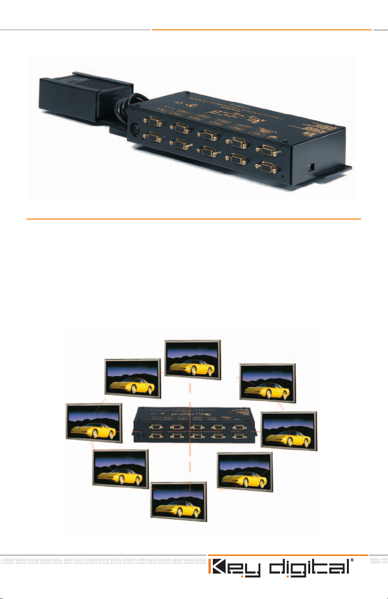
• One unit can drive up to 8 monitors
• The HD View 8
desired from one source
• Each output can drive up to 300 feet each with equal-length VGA cables
Signal Properties
• RGB Video
• Bandwidth -3 dB at 300 MHz, linear-phase passband
• Unity-gain, 0.7 volt p-p, terminated to 75 ohms
• H and V sync TTL type 5 volts p-p
Input
TM
can be cascaded to other HD View 8TMunits to drive as many outputs as
• One DB15 VGA connector for connecting the “source” signal to the HD View 8TMfor
distribution to the output.
Loop Through
• One DB15 VGA connector for connecting the “source” signal to an additional HD View 8
for distribution to additional video displays.
Outputs
• Eight DB15 female connector for connecting the HD View 8TMto the outputs.
TM
Page 5

The Experts in Digital Video Technology and Solutions.
HD View 8TMOperating Instructions
Mechanical
• Easy to install and integrate
• Cables attach to only one side of the unit
• all video inputs and outputs have DB15 (VGA) female connectors
• The 1U-high unit may be oriented horizontally, or mounted vertically on a wall
• Size: 12 3/16" x 5 1/8" x 1 13/16"
• Weight: 5.5 lbs.
• Enclosure type: Metal (no vents)
• Input Power: External power supply provided, 110-240VAC, 50-60 Hz, 0.9 A
Modes of Operation
The HD View 8TMcan be configured for two different modes of operation.
Page 5 of 8
1) 75 Ohm termination mode for stand alone distribution applications or as the terminating
unit at the end of a “daisy-chain” of HD View 8
TM
units. This is the factory default mode
of operation.
2) High Impedance Loop through mode for “daisy-chaining”. This mode must always be
TM
used when connecting to an additional HD View 8
unit.
Product Hookup
After unpacking the unit make sure to make all connections before plugging in the power
adapter.
TM
The HD View 8
er source and distribute to VGA based monitors. A typical hookup will consist of a “source”
device which should be hooked up to the DB15 input. Formats accepted include all SD and
HD formats: 480i, 480p, 720p,1080i/540p and VESA-based PC formats from 640x480 to
1600x1200 with refresh rates 50 Hz to 80 Hz. After hooking up the “Source” device to the
marked input connector, the HD View 8
hooked up to the output DB15 connectors. If you need to distribute the “source” to more
than 8 monitors, you can “daisy-chain” the HD View 8
High Impedance loop through mode of operation. When using a daisy chain of HD View 8
you need to connect the loop-through DB15 connector on the first unit to the DB-15 input
or of the next unit in the chain. Use also need to set the mode of operation as noted
t
c
conne
in the next paragraph of this manual.
will receive virtually any RGBHV signal from a HDTV multimedia or comput-
TM
will distribute this source up to 8 monitors that are
TM
to another HD View 8TMby using the
TM
s,
Page 6

Page 6 of 8
HD View 8TMOperating Instructions
Setting the Mode of Operation
The HD View 8TMshould come from the factory set for single use (terminated or non daisy
chain) operation. The four DIP switches on the side of the unit are used to set the mode of
operation.
Mode One (factory default)
For single use, the switches should all be set in the On (Up) position. (75 Ohm termination
mode)
Mode Two
If you are using the HD View in the daisy chain mode, all switches should be set in the Off
(Down) position (High Impedance Loop mode). Please note that the last unit in the daisy
chain should have its switches set in the On (Up) position (75 Ohm termination mode).
Power Supply Hook Up
After making sure that all hook ups are secure and the settings for the mode of operation is
correct, you need to connect the AC to DC wall power converter. Thus converter has a multipin plug that fits into the connector panel of the HD View 8
entation of the plug is correct to avoid bending the pins on the plug. After attaching the plug
to the HD View 8
TM
connect the AC plug into a 115 volt wall outlet.
TM
. Please make sure that the ori-
Operation
Once power has been applied, use a reliable “Source” to test your connections . Since the
HD View 8
recommended to leave enough room around the unit to dissipate this heat.
If, after properly connecting all of the devices in the system, the unit fails to properly distribute
the “Source” signal, please check the following:
TM
is a powered device it will produce a minimal amount of heat, therefore it is
No power to the unit.
Make sure that the external power supply is properly connected to a standard 115V
household outlet. For added safety and protection it is always recommended to
use a good quality surge protector. Check to make sure that the power connector is
properly inserted into the HD View 8
cable i
please contact Key Digital
®
technical support hotline at (888) 258-2028 or send an e-mail to
t cut or interrupted anywhere. If the HD View 8
s no
tech@keydigital.com.
TM
.Unplug the adapter from the wall and verify that the
TM
till not functioning properly,
s s
i
Page 7

The Experts in Digital Video Technology and Solutions.
Page 7 of 8
HD View 8TMOperating Instructions
HOW TO CONTACT KEY DIGITAL
®
Repairs and Warranty Service:
n
Should your HD View 8
TM
require warranty service, please contact Key Digital®to obtain a
Returned Materials Authorization (RMA) number
n
Please contact us at either:
n
1-914-667-9700
n
email tech@keydigital.com
Technical Support:
n
For technical questions about using our products, please contact us at either:
n
1-914-667-9700 or Toll-free 1-888-258-2028
n
email tech@keydigital.com
Customer Support
n
For customer support questions about using our products, please contact us at either:
n
1-914-667-9700
n
email customersupport@keydigital.com
WARRANTY
All Key Digital®products are built to high manufacturing standards and should provide years of
trouble-free operation. They are backed by a limited two-year parts and labor warranty.
September 2004
Page 8

The Experts in Digital Video Technology and Solutions.
The Experts in Digital Video Technology and Solutions.
The Experts in Digital Video Technology and Solutions.
HD View 8TMOperating Instructions
Key Digital®, led by digital video pioneer Mike Tsinberg,
develops and manufactures high quality, cutting-edge
technology solutions for virtually all applications where
high quality video imaging is important. Our products are
used by professional broadcasters, corporations, custom
installers, home theater retailers, and consumers.
Web :: www.keydigital.com
Phone
:: 914-667-9700 Fax :: 914-668-8666
 Loading...