

Key Digital KD-PVB, KD-PVBP, KD-PVBPD Operating Instructions Manual
KD-PVB, KD-PVBVP & KD-PVBVPD are passive video transceivers that allow for the
transmission and reception of Color or Black & White single-channel video signals
up to 1,300 feet when paired with a passive receiver, or up to 2,600 feet when paired
with an active receiver.
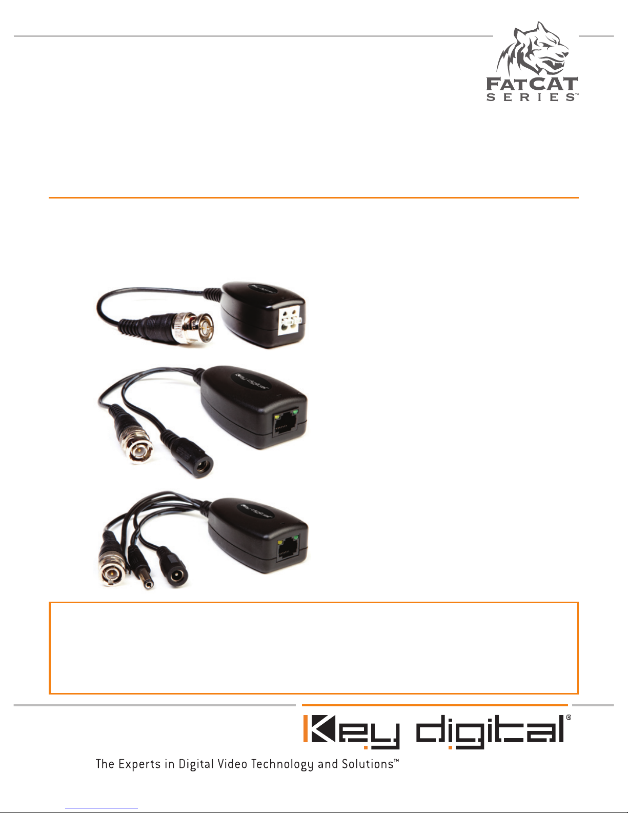
KD-PVB
Passive Video Transceiver
KD-PVBP
Passive Video Transceiver
with Power
KD-PVBPD
Passive Video Transceiver
with Power and Data
Passive Security Baluns
Operating Instructions

Page 2 Page 1
Please read all instructions to insure safe operation of the product.
Key Digital® Security Products Compatibility Chart
Tx
Rx
Passive
Transceiver
Balun
Active
Receiver
Balun
4-Channel
Passive
Receiver
4-Channel
Active
Receiver
Passive
Transceiver
Balun
1300’ 2600’ 1300’ 2600’
Active Video
Balun
Not
Recommended
4000’
Not
Recommended
4000’
4-Channel
Passive
Transceiver
1300’ 2600’ 1300’ 2600’
Note: Distances listed apply to video extension only.
Key Digital® Model Numbers: Security Baluns
➔ Passive Transceiver Baluns
» KD-PVB (Passive Balun with Video)
» KD-PVBVP (Passive Balun with Video and Power)
» KD-PVBVPD (Passive Balun with Video, Power, and Data)
➔ Active Video Baluns
» KD-AUVTX (Active Video Transmitter)
» KD-AUVRX (Active Video Receiver)
➔ Active/Passive 4-Channel Video Hubs
» KD-4PUV (Passive 4-Channel Video Transceiver)
» KD-4AUVRX (Active 4-Channel Video Receiver)
Table of Contents
Key Digital® Security Products Compatibility Chart . . . . . . . . . . . . . . . . . . . . . . . . . 8
KD-PVB
Quick Set Up Guide . . . . . . . . . . . . . . . . . . . . . . . . . . . . . . . . . . . . . . . . . . . . . . . 8
About KD-PVB . . . . . . . . . . . . . . . . . . . . . . . . . . . . . . . . . . . . . . . . . . . . . . . . . . . 8
Installation and Operation. . . . . . . . . . . . . . . . . . . . . . . . . . . . . . . . . . . . . . . . . . . . 8
Video Connections . . . . . . . . . . . . . . . . . . . . . . . . . . . . . . . . . . . . . . . . . . . . . . 8
Uses with Passive Multi-Channel Receivers . . . . . . . . . . . . . . . . . . . . . . . . . . . 8
Uses with Active Receivers & Active Multi-Channel Receivers . . . . . . . . . . . . . . 8
Mechanical / Technical Specifications . . . . . . . . . . . . . . . . . . . . . . . . . . . . . . . . . . 8
KD-PVBVP
About KD-PVBVP . . . . . . . . . . . . . . . . . . . . . . . . . . . . . . . . . . . . . . . . . . . . . . . . . 8
Installation and Operation. . . . . . . . . . . . . . . . . . . . . . . . . . . . . . . . . . . . . . . . . . . . 8
Video Connections . . . . . . . . . . . . . . . . . . . . . . . . . . . . . . . . . . . . . . . . . . . . . . 8
Power Connections . . . . . . . . . . . . . . . . . . . . . . . . . . . . . . . . . . . . . . . . . . . . . 8
Voltage Drop Reference Chart. . . . . . . . . . . . . . . . . . . . . . . . . . . . . . . . . . . . . . 8
Uses with Passive Multi-Channel Receivers . . . . . . . . . . . . . . . . . . . . . . . . . . . 8
Uses with Active Receivers & Active Multi-Channel Receivers . . . . . . . . . . . . . . 8
Pin Assignment for KD-PVBVP . . . . . . . . . . . . . . . . . . . . . . . . . . . . . . . . . . . . . . . 8
Mechanical / Technical Specifications . . . . . . . . . . . . . . . . . . . . . . . . . . . . . . . . . . 8
KD-PVBVPD
About KD-PVBVPD . . . . . . . . . . . . . . . . . . . . . . . . . . . . . . . . . . . . . . . . . . . . . . . . 8
Installation and Operation. . . . . . . . . . . . . . . . . . . . . . . . . . . . . . . . . . . . . . . . . . . . 8
Video Connections . . . . . . . . . . . . . . . . . . . . . . . . . . . . . . . . . . . . . . . . . . . . . . 8
Power Connections . . . . . . . . . . . . . . . . . . . . . . . . . . . . . . . . . . . . . . . . . . . . . 8
Voltage Drop Reference Chart. . . . . . . . . . . . . . . . . . . . . . . . . . . . . . . . . . . . . . 8
Uses with Passive Multi-Channel Receivers . . . . . . . . . . . . . . . . . . . . . . . . . . . 8
Uses with Active Receivers & Active Multi-Channel Receivers . . . . . . . . . . . . . . 8
Pin Assignment for KD-PVBVPD . . . . . . . . . . . . . . . . . . . . . . . . . . . . . . . . . . . . . . 8
Mechanical / Technical Specifications . . . . . . . . . . . . . . . . . . . . . . . . . . . . . . . . . . 8
Important Product Warnings . . . . . . . . . . . . . . . . . . . . . . . . . . . . . . . . . . . . . . . . . 8
Safety Instructions . . . . . . . . . . . . . . . . . . . . . . . . . . . . . . . . . . . . . . . . . . . . . . . . . 8
How to Contact Key Digital . . . . . . . . . . . . . . . . . . . . . . . . . . . . . . . . . . . . . . . . . . 8
Warranty . . . . . . . . . . . . . . . . . . . . . . . . . . . . . . . . . . . . . . . . . . . . . . . . . . . . . . . . 8
Page 2 Page 3
About KD-PVB
➔ Transmits or Receives real-time Color or Black & White video
➔ Extends Black & White video up to 2,600 ft using a standard CAT cable when
used with an Active Receiver (Key Digital models KD-AUVRX or KD-4AUVRX).
➔ Extends Black & White video up to 1,300 ft using a standard CAT cable when
paired with a Passive Transmitter Balun (Key Digital models KD-PVB or KD-4PUV).
➔ Compatible with CAT5/CAT5e/CAT6/CAT7 cabling
Installation and Operation
Before permanently securing the unit for final installation of
cabling behind walls or ceilings, test for proper operation of the
unit and the cables in your system.
Video Connections
➔ Secure twisted pair wires into “+” and “-” pin openings by depressing tabs and
inserting wire
Uses with Passive Multi-Channel Receivers
➔ KD-PVB units can be paired with Key Digital’s KD-4PUV 4-Channel Passive Video
Receiver Hub as part of a multi-camera CCTV system. Using the KD-PVB with
the KD-4PUV Passive Hub will provide equivalent distances as when coupled with
KD-PVB Passive Receiver Balun; 1,300 feet.
Uses with Active Receivers & Active Multi-Channel Receivers
➔ KD-PVB units can be coupled with an Active Receiver (Key Digital model KD-
AUVRX) or an Active Multi-Channel Receiver (Key Digital model KD-4AUVRX) in
your application. Coupling a KD-PVB Passive Transmitter with the KD-AUVRX
Active Receiver Balun or KD-4AUVRX Active 4-Channel Receiver will provide
quality video up to 2,600 ft.
Note: The usage of a KD-PVB balun to receive video signals from an Active Transmitter (Key
Digital model KD-AUVTX) is not recommended. For best results, it is recommended that
the KD-PVB Passive Video Balun be used as the Transmitter, while the KD-AUVRX or KD4AUVRX Active Video Receiver Baluns be used as the Receiver.
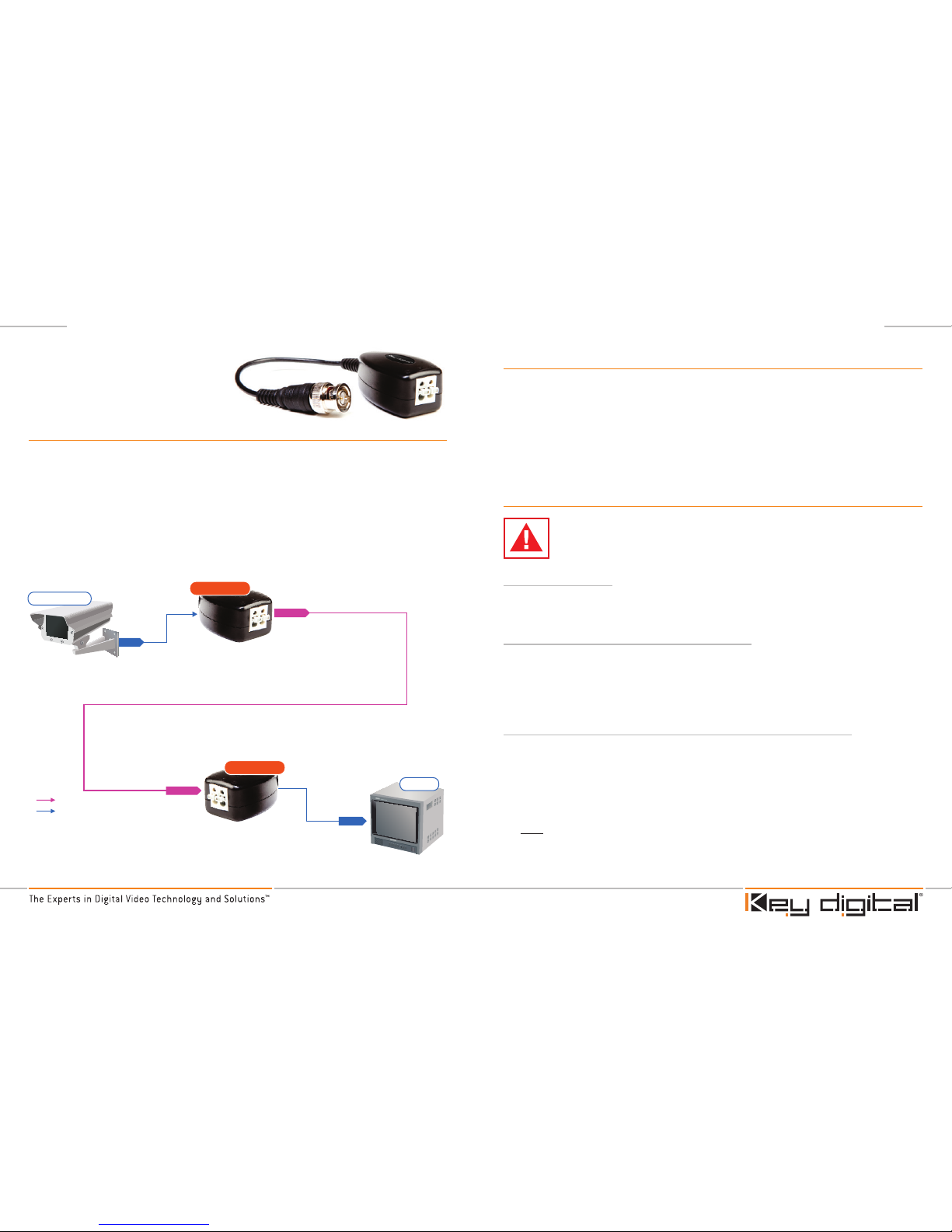
Video
CAT5/6/7
1,300’
KD-PVB
KD-PVB
CAT5/6/7
CAT5/6/7
Video
Video
Monitor
Security Cam
KD-PVB
Passive Video Transceiver
Quick Setup Guide
Step 1: Begin with all input/output devices turned off with power cables removed.
Step 2: Connect video source into BNC connector of Transmitter Balun.
Step 3: Secure twisted pair wires into “+” and “-” pin openings.
Step 4: Repeat Steps for Receiver Balun. Connect video display and/or DVR to
BNC connector of Receiver Balun.
Step 5: Power on all input/output devices.
Page 4 Page 5
Mechanical / Technical Specifications
Tx Input / Rx Output
1 BNC connector for Composite Video 1Vpp with
75Ω at display side or Audio SPDIF or any other
format of video, audio, RS-232 or IR signaling.
Tx Output / Rx Input
1 twisted pair from CAT5 line In on Phoenix type
stripping and cramping connector
Max. Signal Input /
Output Level:
Composite: 1.2Vpp on 75Ω terminated at display,
DC coupling or Line Audio or TTL +5V for digital
RS-232, IR signaling
Surge Protection
Renewable solid state surge protection.
Bandwidth
DC to 6 MHz
Video Format
NTSC, PAL, SECAM
Impedance
BNC side 75Ω unbalanced,
UTP side 100Ω balanced
Humidity
0% to 95% non condensing
Distance
4000 feet Active Tx with Active Rx Coupling,
2000 feet Passive Tx with Active Rx coupling
Equalization
Passive impedance matching and fixed equalization.
Video S/N Ratio:
58 dB RMS un-weighted;
65 dB RMS @5MHz weighted
Ground Isolation
Ground connection available for STP or Ground
loop removal
Power Source:
DC/AC 9-12V
Dimensions:
LxWxH: 2.5”x1.5”x 1” excluding BNC
Weight:
<.25 lb
Operating Temperature
-14F to +120F
Accessories:
None
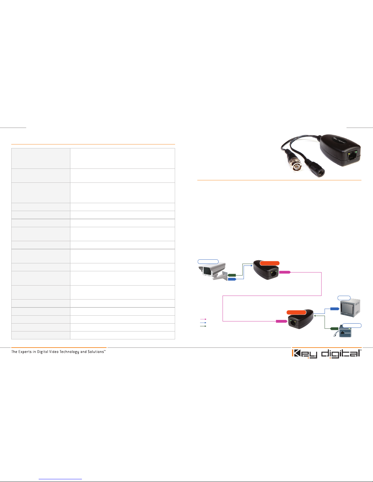
KD-PVBP
Passive Video Transceiver
with Power
Quick Setup Guide
Step 1: Begin with all input/output devices turned off with power cables removed.
Step 2: Connect video source into BNC connector of Transmitter Balun.
Step 3: Connect Male Power plug into power jack of camera / video source.
Step 4: Connect CAT/5/6/7 cable to Transmitter Balun output.
Step 5: Repeat Steps for Receiver Balun. Connect video display and/or DVR to
BNC connector of Receiver Balun.
Step 6: Connect Female Power jack with Male Power plug of power supply
(not included).
Step 7: Connect CAT5/6/7 cable to Receiver Balun input.
Step 8: Power on all input/output devices.
Video
CAT5/6/7
CAT5/6/7
Video
Power
1,300’
1,300’
KD-PVB
KD-PVB
KD-PVBP
KD-PVBP
CAT5/6/7
CAT5/6/7
Video
Video
CAT5/6/7
CAT5/6/7
Video
Power
Power
Video
*Distance specified is for Video ONLY.
Please refer to Voltage Drop Reference Chart for Power extension lengths.
Monitor
Monitor
Power Supply
Security Cam
Security Cam
 Loading...