

Key Digital KD-Pro6x6CC, KD-Pro8x8CC Operating Instructions Manual
Key Digital®, led by digital video pioneer Mike Tsinberg,
develops and manufactures high quality, cutting-edge
technology solutions for virtually all applications where
high-end video and control are important. Key Digital
®
is at the forefront of the video industry for Home Theater
Retailers, Custom Installers, System Integrators,
Broadcasters, Manufacturers, and Consumers.
HDBaseT/HDMI via Single CAT5e/6
Matrix Switchers with built-in
Compass Control
®
,
support Ultra HD/4K & HDCP 2.2
The Experts in Digital Video Technology and Solutions
™
KD-Pro8x8CC
KD-Pro6x6CC
Operating Instructions
Rev 0 – Apr 2016
Key Digital® Systems :: 521 East 3rd Street :: Mount Vernon, NY 10553
Phone : 914.667.9700 Fax : 914.668.8666 Web : www.keydigital.com
KD-Pro6x6_8x8CC_Manual.indd 2-3 4/25/16 5:07 PM
4 1
Table of Contents
About KD-Pro6x6/8x8CC ..................................................... 1
About KD-XSWRx ........................................................... 2
Connections, Buttons and LEDs ................................................ 3
Application Example ......................................................... 5
Quick Setup Guide .......................................................... 6
Extending and Routing Control Signals ........................................... 7
Settings................................................................... 9
Remote Control ............................................................ 10
RS-232 & TCP/IP Commands ................................................. 12
Firmware Upgrade.......................................................... 17
Audio Return Channel ....................................................... 20
Using the KD-Pro6x6/8x8CC in a Compass Control project .......................... 21
Specifications ............................................................. 25
Important Product Warnings & Safety Instructions: ................................. 26
How to Contact Key Digital ................................................... 27
Warranty Information ........................................................27
About KD-Pro6x6/8x8CC
Key Digital® KD-Pro6x6/8x8CC are HDBaseT®/HDMI via CAT5e/6 Matrix
Switchers with built-in Compass Control
®
master controller, capable of
switching 6/8 HDMI Inputs to 6/8 Independent Zones via Single CAT5e/6
with UHD/4K and HDCP 2.2 support.
Key Features
› Simultaneously Active:
6/8 HDBaseT (CAT5e/6 RJ45) and 6/8 HDMI outputs with fully
automatic CAT5e/6 cable equalization. Supports up to 12/16 TVs (6/8 mirrored)
› Compass Control
®
Inside:
Key Digital’s Compass Control® control system is built-in, negating
the need for an external master controller (supports up to 27/33 control ports)
› Includes:
3/4 KD-XSWRx Receiver Extenders
› HDBaseT:
Utilized on CAT5e/6 RJ45 outputs
› Signal Extension:
» Up to
250 feet
@ 1080p/60, 1080p/24, 1080i, 720p
» Up to
150 feet
@ 4K/Ultra HD with KD-XSWRx extenders and approved Key Digital
CAT5e/6 cabling. Compatible with third-party CAT5e/6 with lesser distance performance.
› Ultra HD/4K:
4096x2160/24 video resolution support for Ultra HD capable TVs and commercial
applications such as Digital Movie Theaters, CAD, Post Production
› HDR:
Supports High Dynamic Range technology with EDID copy from HDR supporting display
› 3D Ready:
Capability to pass 3D stereoscopic signal formats
› Audio Return Channel:
Allows audio to be returned from a display to an HDMI output, for
audio distribution (HDMI outputs only, using 3.5mm I/O port and 3.5mm to PCM cable)
› EDID:
Internal library with 15 default EDID configurations for each input, in addition to native EDID
data for any Output/Display
› Full Buffer
™
Technology
: Full buffering of HDCP and EDID, for the fastest possible switching
and viewing of any source/input to any display/output, regardless of multiple output viewing
relation
› TMDS re-clocking
: Support for long HDBaseT/CAT5e/6 or HDMI connections
and many layers of connectivity.
› Voltage Trigger:
I/O ports may be used as a voltage trigger in Compass Control® system
› Relay Support:
3.5mm I/O ports may be used as relays to support contact closure/opening,
when used with an external relay board
› Lossless Compressed Digital Audio:
Dolby® TrueHD, Dolby® Digital Plus, Dolby
®
Atmos
and DTS-HD Master Audio
™
› Deep Color Support:
Up to 12 bits/color
› Control Routing:
Enables bi-directional IR/RS-232 control signal extension
› Control:
Front panel push buttons and LEDs, TCP/IP, USB Port, Optical IR front/rear, Serial IR,
RS-232 with full bi-directional operation
› Control System Support: Compatible with Compass Control
®
, AMX®, Control4®, Crestron®,
KNX
®
, RTI®, Savant, URC®, Leviton®, etc.
Accessories
› 3/4 KD-XSWRx Receiver Extenders
› Two external power supplies. Main: +6V/11.6A (70W); POH for KD-XSWRX : +12V/6.6A (80W)
› IR Remote control, 6 ft. USB Data Cable
© 2016 Key Digital, Inc. All rights reserved.
Always follow the instructions provided in this Operating Manual.
Please check the Key Digital Website for the most up-to-date Manual.
KD-Pro6x6_8x8CC_Manual.indd 4-1 4/25/16 5:07 PM
2 3
Rack Mounting:
› Secure the rack ears to each side of the
KD-Pro6x6/8x8CC
with the supplied hardware, then,
fasten the unit to the rack rails with the included machine screws.
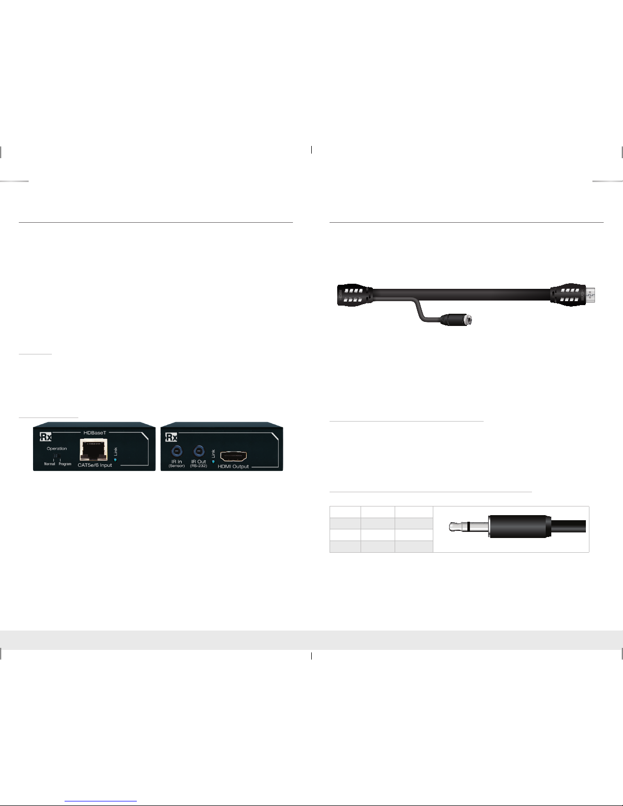
About KD-XSWRx
› Signal Extension:
» Up to 150 ft. @ 4K 24/25/30(4:4:4)/60(4:2:0) using KD-CAT6STP1X cabling
» Up to 125 ft. @ 4K 24/25/30(4:4:4)/60(4:2:0) using third-party CAT5e/6 UTP/STP cabling
» Up to 250 ft. @ 1080p / 1920x1200 using KD-CAT6STP1X cabling
» Up to 230 ft. @ 1080p / 1920x1200 using third-party CAT5e/6 UTP/STP cabling
› 4K/Ultra HD Resolution: Support for 4096x2160 or 3840x2160 24/25/30Hz at 4:4:4/8 Bit or
60Hz at 4:2:0/8 Bit
› HDMI
®
and HDCP Licensing: Fully licensed and compatible with HDCP 2.2 and HDMI latest
technology such as 4K/UHD 4:2:0/8bit at 60f/s
› EDID Control: Internal library features 15 default EDID configurations and native EDID data from
Output/Display devices connected via Rx
› Full Buffer System
™
: Manages TMDS re-clocking / signal re-generation, HDCP authentication
with source & display, EDID Control handshake, and Hot Plug control
› IR Sensor: Sensor powering via +5V on Rx unit’s IR In port collects line-of-sight IR from remote(s)
without external IR connecting block
› Up/Down IR: Two channels of IR enable control to/from connected devices
› RS-232: Bi-Directional control to/from on 3.5mm connector
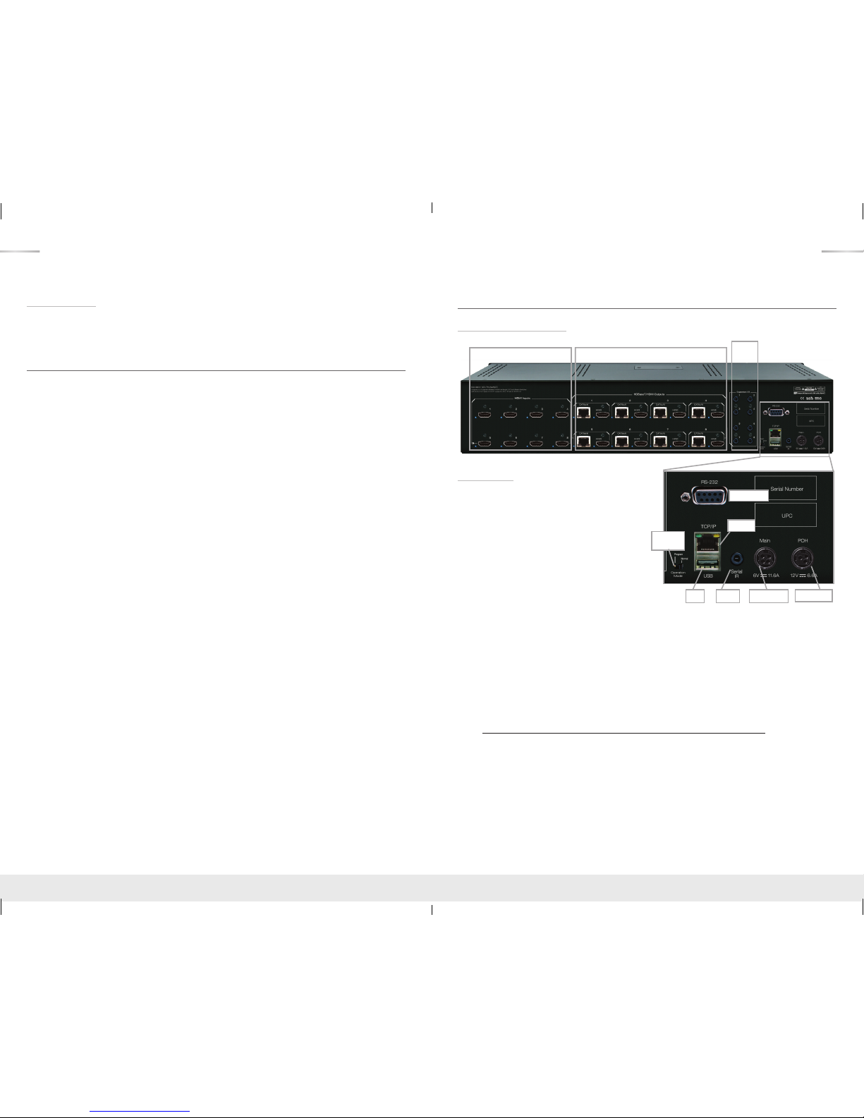
Connections, Buttons and LEDs
Rear Panel Connections:
HDMI Inputs & LEDs
I/O
Ports
HDMI & CAT5e/5 Outputs & LEDs
Operation
Mode
RS-232 Port
POH PowerMain PowerIR EyeUSB
TCP/IP
Connections
› HDMI Inputs: Located on the left side of the
back panel. The Inputs have a blue LED that
will illuminate when a source is connected and
synced.
› HDMI & CAT5e/6 Outputs: Located in the
middle of the back panel. The Outputs have
a blue LED that will illuminate when a output
device is connected and synced.
› The RS-232, Serial IR, Optical IR Sensor,
Operation Mode Switch, TCP/IP, USB and
Power are located on the right side of the
back panel.
» Two power connections are necessary. Main Unit power and POH power.
› I/O Ports: Located to the right of the Outputs
» Used for control extension/routing and ARC.
› The Operation Mode switch is used to update the unit’s firmware, which is done via RS-232,
USB or TCP/IP. The firmware version as well as all RS-232 commands is available through the
RS-232 command ‘H’. A detailed list of RS-232 commands are available later in this guide.
› If newer firmware is made available, complete updating instructions will be included with it. Check
the Key Digital website for any firmware updates.
» www.keydigital.com/items.asp?ItemCode=KDPro8x8CC&Company=KEY
KD-Pro6x6_8x8CC_Manual.indd 2-3 4/26/16 2:52 PM
4 5
Front Panel Buttons and LEDs
IR Eye
Input LEDs
Output Select Buttons
› There are 6/8 Output buttons along the front panel.
› Pressing an output button will select the next HDMI input.
› A blue LED will indicate which Input has been selected for each Output.
› There is also an Optical IR window located on the right side of the front panel for IR remote control
signals.
› Video Output MUTE is indicated by the outermost LEDs remaining illuminated,
while the inner LEDs are not.
› Video Output Off is indicated when the innermost LEDs are illuminated,
while the outermost are not.
› Reset is optional by holding the input select buttons “1” and “4” for 10 seconds.
» Successful reset indicated by reboot.
» Reboot will flash all input lights on the front panel in a back and forth motion until only one
input is selected per output.
KD-XSWRx LED Indicator Lights
› Power:
» Color: Green
» Solid illumination during power ON state, as provided by healthy connection with power
supply
» Steady blink if power is not adequate and/or if there is a connectivity problem with KD-
Pro6x6/8x8CC unit
› HDMI Active (HDMI Input/Output):
» Color: Blue
» Solid illumination from active Hot Plug Detection voltage with connected display/output
device
» If Hot Plug Detection is forced to input device from Tx unit, the HDMI Active light will
illuminate solid regardless of HDMI signal from connected device.
› CAT5e/6 Input/Output:
» Color: Blue
» Solid illumination from active link with KD-Pro6x6/8x8CC unit
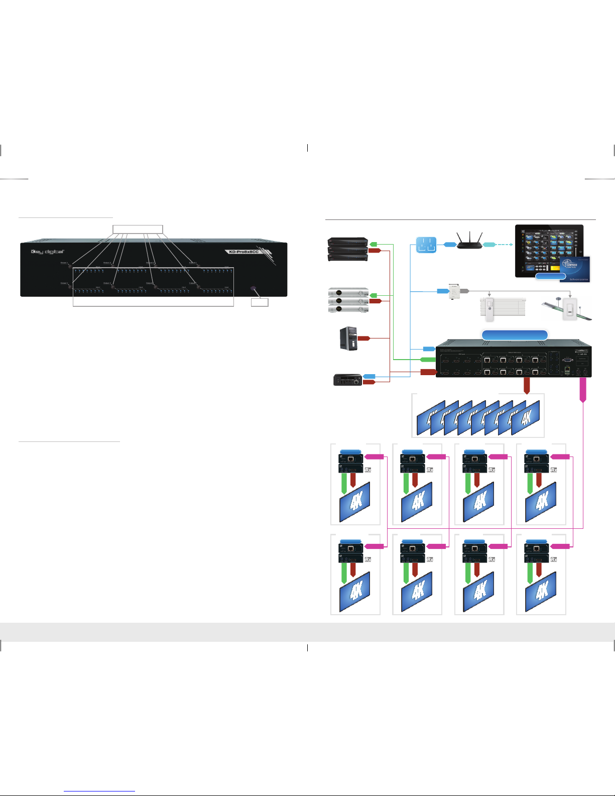
Application Example
PC
Satellite (x3)
Cable (x3)
Ultra HD/4K
Digital Signage
WiFi Router
CAT5e/6
Ethernet
KD-Pro8x8CC
RJ45
x8
x8
x3
x3
HDMI
HDMI
RJ45
HDMI
IR
IR
IR/RS232
iPad
KD-CSLX1
Bar Area - Mirrored Diplays 1-8
HDMI
RJ45
WiFi
Reception
HDMI
IR/RS232
CAT5e/6
KD-XSWRx
Dining 1
HDMI
IR/RS232
CAT5e/6
KD-XSWRx
Dining 2
HDMI
IR/RS232
CAT5e/6
KD-XSWRx
2nd Floor
HDMI
IR/RS232
CAT5e/6
KD-XSWRx
Restrooms
HDMI
IR/RS232
CAT5e/6
KD-XSWRx
Deck 1
HDMI
IR/RS232
CAT5e/6
KD-XSWRx
Deck 2
HDMI
IR/RS232
CAT5e/6
KD-XSWRx
Main Hall
HDMI
IR/RS232
CAT5e/6
KD-XSWRx
HDMI
RF Repeater
(Light/Shade Control)
RF
RJ45
Lights
Shades
HDMI
Up to
150 ft.
@ 4K
KD-Pro6x6_8x8CC_Manual.indd 4-5 4/25/16 5:07 PM
6 7
Quick Setup Guide
1. Begin with the KD-Pro6x6/8x8CC and all input/output devices turned off and power cables
removed.
2. Connect HDMI sources to the appropriate input ports on the KD-Pro6x6/8x8CC.
3. Connect CAT5e/6 outputs to the KD-XSWRx extenders via CAT5e/6 cables, then connect
the extenders to the output devices (display, projector, AV Receiver, etc).
4. Connect HDMI outputs to the appropriate output device (outputs will mirror CAT5e/6).
5. Connect both power supplies (one for the Matrix and one for the POH Extenders) to the KDPro6x6/8x8CC and all other input and output devices and turn them on.
6. Operate the KD-Pro6x6/8x8CC switcher via front panel buttons, IR Remote, Serial IR or RS232 control.
7. If TCP/IP control is desired, load latest firmware and set the IP address using Device Manager
software. See firmware upgrade section.
Operation:
After performing the setup above, the unit is ready for operation.
There are several options for controlling the unit. Commands can be issued via IR remote control,
RS-232, TCP/IP or by using the front panel buttons. Note that the advanced commands are
available only via TCP/IP and RS-232 protocol.
KD-XSWRx Baluns
If you will be utilizing the KD-XSWRx extender, please follow this procedure.
› One CAT5e/6 UTP or STP cable needs to be used.
› Use the shortest possible HDMI cable when connecting the
KD-XSWRx
to the Display. Key Digital
recommends cables 6 ft. or shorter for optimum performance.
› Ensure the CAT5e/6 cable runs directly from the switcher to the
KD-XSWRx
.
› Do not use patch panels, punch downs, keystones, couplers, wall plates, etc..
› Key Digital recommends the use of CAT5e/6 STP cable with shielded RJ45 connectors
for optimum performance and distances from your extender.
Extending and Routing Control Signals
› The KD-Pro6x6/8x8CC feature powerful and useful control routing features. The switchers have
the ability to matrix control signals just like it can HDMI signals.
› KD-Pro6x6/8x8CC can consolidate incoming IR/RS-232 signals to control any display/output
connected via CAT5/6 or via HDMI (control signal extension via HDMI only available with Key
Digital KD-IQJUMP12FM, female to male HDMI jumper cable for insertion or extraction of IR or
Bi-Directional RS-232).
› KD-Pro6x6/8x8CC can consolidate incoming IR/RS-232 signals to control any source/input
connected via HDMI, with Key Digital’s KD-IQJUMP12FM jumper cable.
› IR and RS-232 control signals are bi-directional, and may flow from the matrix to the zone or from
the zone to the matrix.
› The default signal path for control signals is to route IR control signals from Expansion I/O Port 1
to RJ45 output 1…Expansion I/O Port 8 to RJ45 Output 8 (the path and control signal type can
be manipulated by using the desired RS-232 command).
› When connecting the IR Emitter to the device you wish to control, make sure to find the IR
receiver area on the device.
Control Signal Extension from External I/O Ports:
The default setting for control signal extension is to route IR signals from Expansion I/O Port 1 to
RJ45 output 1…Expansion I/O Port 8 to RJ45 Output 8 (the path and control signal type can be
manipulated by using the desired RS-232 command). When routing control signals to/from an
HDMI input/output, Key Digital’s KD-IQJUMP12FM jumper cable must be used.
› Point-to-Point control routing is established by using commands containing “IRR” or “RSS”.
› Point-to-Many control routing is established by using commands containing “IR” or “RS”.
Extension I/O and Digital Audio Output (ARC) Port Configuration
Supports IR or RS-232 routing or ARC output. See chart below for 3.5mm jack configuration:
Tip Ring
IR TX or RX None
RS232 TxD RxD
ARC NONE ARC OUT
Note: If ARC is enabled, IR and RS-232 signal routing will be disabled.
KD-Pro6x6_8x8CC_Manual.indd 6-7 4/25/16 5:07 PM
 Loading...