

Key Digital KD-MSW4x2Pro Operating Instructions Manual

521 East 3rd Street, Mount Vernon, NY 10553
Phone :: 914.667.9700 Fax :: 914.668.8666
Web :: www.keydigital.com
KD-MSW4x2Pro Operating Instructions
Operating Instructions
Key Digital™, led by digital video pioneer Mike Tsinberg,
develops and manufactures high quality, cutting-edge
technology solutions for virtually all applications where
high quality video imaging is important. Key Digital™
is at the forefront of the video industry for Home
Theater Retailers, Custom Installers, System Integrators,
Broadcasters, Manufacturers, and Consumers. We
provide
total video system solutions because we
know and help drive the technology, the industry, the
business, and all the latest up-and-coming standards.
But most of all, we know exactly what you need for your
unique application - the right solution.
Rev 0 – July 2006
The KD-MSW4x2Pro by Key Digital™ is an analog HDTV Fat Boy Series 4-Input to 2-Output matrix
switcher and distribution amplifier that is available in a variety of convenient output expansion
packages. For each of the two displays connected to the output of a base unit, any of up to
four source inputs can be separately and seamlessly switched with the professional Fade-toBlack and Video Muting features. It supports both component video (YPbPr) and RGBHV video
formats; and S-Video and composite video (CVBS), with adapters. Concurrent with the video, it
switches and distributes PCM coax digital audio, and analog stereo audio (no analog audio for
RGBHV video) with convenient volume control. With analog video bandwidths up to 300 MHz,
the KD-MSW4x2Pro handles all HD and SD resolutions (50 and 60 Hz) including 1080p/60, with
no degradation in signal quality. It is simple to operate and control via front panel pushbuttons
with LEDs to monitor the selections, IR remote control, IR Extender, wired IR, and is compatible
via RS-232 with all control systems.
KD-MSW4x2Pro
4 Inputs to 2 Outputs RGBHV Matrix Switcher with Volume Control
These Operating Instructions apply to the entire Key Digital™
Fat Boy Series line of KD-MSW4x2Pro HDTV Matrix Switchers:
KD-MSW4x2Pro . . . . . . . . . . 4 x 2 HDTV Matrix Switcher (single base unit, stand alone)
KD-MSW4x4Pro . . . . . . . . . . 4 x 4 HDTV Matrix Switcher (2 base units of 4x2 and Cable Kit)
KD-MSW4x6Pro . . . . . . . . . . 4 x 6 HDTV Matrix Switcher (3 base units of 4x2 and Cable Kit)
KD-MSW4x8Pro . . . . . . . . . . 4 x 8 HDTV Matrix Switcher (4 base units of 4x2 and Cable Kit)
MSW4x2Pro_Manual.indd 2-1 8/23/06 4:09:48 PM
KD-MSW4x2Pro Operating Instructions
Page 2
KD-MSW4x2Pro Operating Instructions
Page 1
Table of Contents
Quick Setup Guide . . . . . . . . . . . . . . . . . . . . . . . . . . . . . . . . . . . . . . . . . . . . . . . . . . . . . . . . . . 1
Fat Boy Series Expansion . . . . . . . . . . . . . . . . . . . . . . . . . . . . . . . . . . . . . . . . . . . . . . . . . . . . . 5
Introduction . . . . . . . . . . . . . . . . . . . . . . . . . . . . . . . . . . . . . . . . . . . . . . . . . . . . . . . . . . . . . . . . 6
Terminology . . . . . . . . . . . . . . . . . . . . . . . . . . . . . . . . . . . . . . . . . . . . . . . . . . . . . . . . . . . . . . . . 8
Matrix Switching . . . . . . . . . . . . . . . . . . . . . . . . . . . . . . . . . . . . . . . . . . . . . . . . . . . . . . . . . . . . 6
What’s Included . . . . . . . . . . . . . . . . . . . . . . . . . . . . . . . . . . . . . . . . . . . . . . . . . . . . . . . . . . . . . 11
Quick Facts About the KD-MSW4x2Pro. . . . . . . . . . . . . . . . . . . . . . . . . . . . . . . . . . . . . . . . . . .12
Examine the Front and Rear Panels . . . . . . . . . . . . . . . . . . . . . . . . . . . . . . . . . . . . . . . . . . . . . .14
Connecting the Video and Audio Inputs and Outputs . . . . . . . . . . . . . . . . . . . . . . . . . . . . . . . . .16
Detailed Input/Output Descriptions . . . . . . . . . . . . . . . . . . . . . . . . . . . . . . . . . . . . . . . . . . . . . .19
Control Connections . . . . . . . . . . . . . . . . . . . . . . . . . . . . . . . . . . . . . . . . . . . . . . . . . . . . . . . . .21
Applying Power . . . . . . . . . . . . . . . . . . . . . . . . . . . . . . . . . . . . . . . . . . . . . . . . . . . . . . . . . . . . 23
Operation . . . . . . . . . . . . . . . . . . . . . . . . . . . . . . . . . . . . . . . . . . . . . . . . . . . . . . . . . . . . . . . . .24
IR Remote Control . . . . . . . . . . . . . . . . . . . . . . . . . . . . . . . . . . . . . . . . . . . . . . . . . . . . . . . . . . 26
RS-232 Commands and Protocol . . . . . . . . . . . . . . . . . . . . . . . . . . . . . . . . . . . . . . . . . . . . . . 30
Technical Specifications . . . . . . . . . . . . . . . . . . . . . . . . . . . . . . . . . . . . . . . . . . . . . . . . . . . . . . 33
How to Contact Key Digital™ . . . . . . . . . . . . . . . . . . . . . . . . . . . . . . . . . . . . . . . . . . . . . . . . . . 37
© 2006 Key Digital, Inc. All rights reserved.
Quick Setup Guide
Fat Boy Series Expansion
The KD-MSW4x2Pro is available as a stand-alone base unit, or pre-wired from Key Digital™ as
multiple Fat Boy units from the factory in an expanded configuration. For control, each unit in the
expansion is individually addressable.
Basics Facts About the KD-MSW4x2Pro
The KD-MSW4x2Pro is a 4-Input to 2-Output video and audio matrix switcher and distribution
amplifier that is available pre-wired from the factory in a variety of output expansion packages.
Each stand-alone base unit has two distinct outputs that can be used to drive two separate
displays and audio / surround sound systems. One of up to four source input devices can be
independently and separately selected to drive each of the two displays and audio systems. The
product provides professional-grade switching, with the Fade-to-Black and Video Mute features,
preventing image glitches when switching between sources. Features an audio volume control for
the left and right analog audio channels.
Typical source input devices that can be matrix switched with the KD-MSW4x2Pro include:
DVD players and changers
Cable TV, satellite, and terrestrial Set Top Boxes (STBs)
Digital Video Recorders (DVRs)
D-VHS, S-VHS and VHS VCR’s
Electronic game boxes
Personal Computers (PCs)
The KD-MSW4x2Pro handles all HD and SD resolutions, and is compatible with all standard analog
video signal formats, including:
1080p, 1080i, 720p, 576p, 576i, 540p, 480p, 480i
50 Hz or 60 Hz refresh rates
The KD-MSW4x2Pro performs no video or audio processing, and supports video bandwidths up
to 300 MHz. Its output stage drives high-quality, equal-length video cables up to 300’ or more.
The output formats and resolutions are identical to those at the input to the unit.
The KD-MSW4x2Pro uses BNC connectors for video and audio inputs and outputs, and supports
both component video (YPbPr) and RGBHV video formats; as well as S-Video and composite video
(CVBS), with adapters. Along with the video, it concurrently switches and distributes PCM coax
digital audio, and analog stereo audio (for YPbPr operation only). A volume control is provided for
the analog left and right stereo audio.
›
›
›
›
›
›
›
›
If the user or installer is familiar with Video/Audio Matrix Switching and Distribution,
then the following Quick Setup Guide can be used as a shortcut. It is recommended
to always follow all the detailed instructions provided in this entire Operating Manual
to properly hook-up, operate, and control the KD-MSW4x2Pro product.
CAUTION: If purchased as a Fat Boy expansion of the base 4x2
matrix switcher configuration, the multiple base units will come
pre-connected and tested from the factory. It is advised NOT to
disconnect or reconfigure any of these cables.
MSW4x2Pro_Manual.indd 2-1 8/23/06 4:09:51 PM
KD-MSW4x2Pro Operating Instructions
Page 2
KD-MSW4x2Pro Operating Instructions
Page 3
Quick Installation
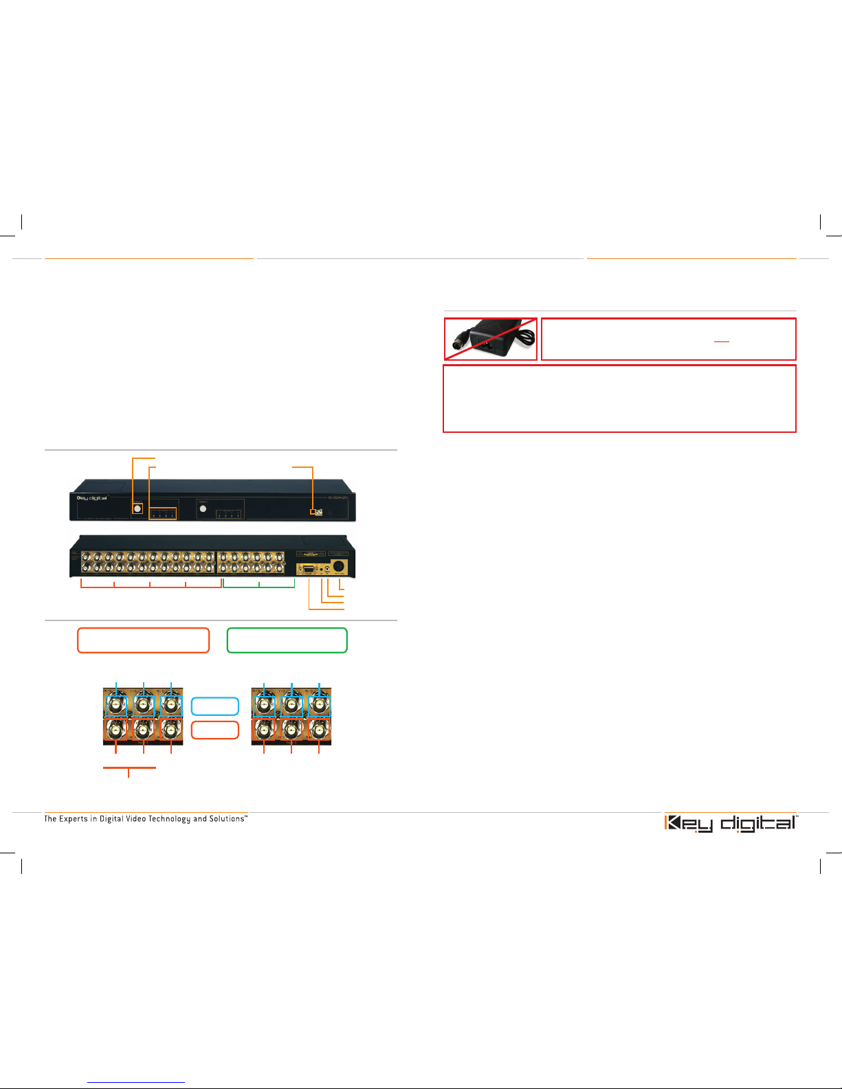
Connect up to four source devices to the Input Ports 1 - 4 on the rear panel
of the KD-MSW4x2Pro unit.
Connect two displays to the Output Ports 1 and 2 on the rear panel of the
KD-MSW4x2Pro unit. If purchased as a Fat Boy expansion, connect the appropriate
number of outputs to all of the pre-wired units.
Input/Output Ports and Formats
The output format = the format of the selected input source
Each Port supports:
YPbPr component video, analog stereo left and right audio, and digital PCM audio
RGBHV video and digital PCM audio
RGB video with sync on the green channel, analog stereo left and right audio, and digital PCM
audio
S-Video and composite video (CVBS), with adapters
Each connector can accommodate various signals, on a shared basis:
PR/R Connector:
Pr label is for component video
R label is for the red channel for RGBHV video
Y/G Connector:
Y label is for component video
G label is for the green channel for RGBHV video
Pb/B Connector:
Pb label is for component video
B label is for the blue channel for RGBHV video
L/H Connector:
L label is for the left analog stereo audio channel
H label is for the horizontal sync for RGBHV video
›
›
›
›
➔
➔
➔
➔
›
➔
»
»
➔
»
»
➔
»
»
➔
»
»
CAUTION: Do not connect the external supply (provided) to
the back of the KD-MSW4x2Pro unit until ALL of your video
and audio connections are completed.
Video
Audio
Component Video Applications
Inputs and Outputs
RGBHV Video Applications
Inputs and Outputs
Pr Y Pb
Left (L) Right (R) Digital
PCM
R G B
H V Digital
PCM
Component Video
RGBHV Video
Analog
Stereo
Audio
Digital
Audio
Digital
Audio
If video sync is
on Green (G), then
Analog Stereo Audio
is also supported
here in place of H&V
For proper operation of the high quality electrical circuits in the KD-MSW4x2Pro
unit, do NOT "daisy chain" inputs:
Each input of the KD-MSW4x2Pro has its own 75 Ω termination
Do NOT feel a source to multiple KD-MSW4x2Pro inputs without proper
distribution equipment
➔
➔
Inputs
Outputs
Power Supply
Wired IR
IR Extender
RS-232
1 2 1 23 4
Pushbutton to Select Input
Input Selected LEDs
IR Remote Sensor
Front and Rear Panels
Typical Input/Output Port
The KD-MSW4x2Pro base unit has four (4) Input Ports and two (2) Output Ports. Each Input Port
and Output Port is comprised of six (6) BNC connectors:
3 analog video connectors (YPbPr or RGB, shared as Pr/R Y/G Pb/B)
2 analog audio connectors (Left and Right stereo pairs)
The analog audio input/output connectors also serve as the horizontal (H) and vertical (V) sync
for RGBHV signals
1 PCM digital coax audio connector
The KD-MSW4x2Pro Fat Boy expansions have four (4) Input Ports and expanded Output Ports:
KD-MSW4x4Pro: 4 output ports
KD-MSW4x6Pro: 6 output ports
KD-MSW4x8Pro: 8 output ports
›
›
›
›
›
›
›
MSW4x2Pro_Manual.indd 2-3 8/23/06 4:09:58 PM
KD-MSW4x2Pro Operating Instructions
Page 4
KD-MSW4x2Pro Operating Instructions
Page 5
R/V Connector (Right analog stereo audio, or vertical sync for RGBHV video)
R label is for the right analog stereo audio channel
V label is for the vertical sync for RGBHV video
PCM Connector:
For PCM digital coax audio
Control Connections
Decide how the KD-MSW4x2Pro will be controlled
If using an IR (Infrared) Extender, the wired IR, or an external Control System (via the RS-232 port
on the KD-MSW4x2Pro), make the appropriate connections
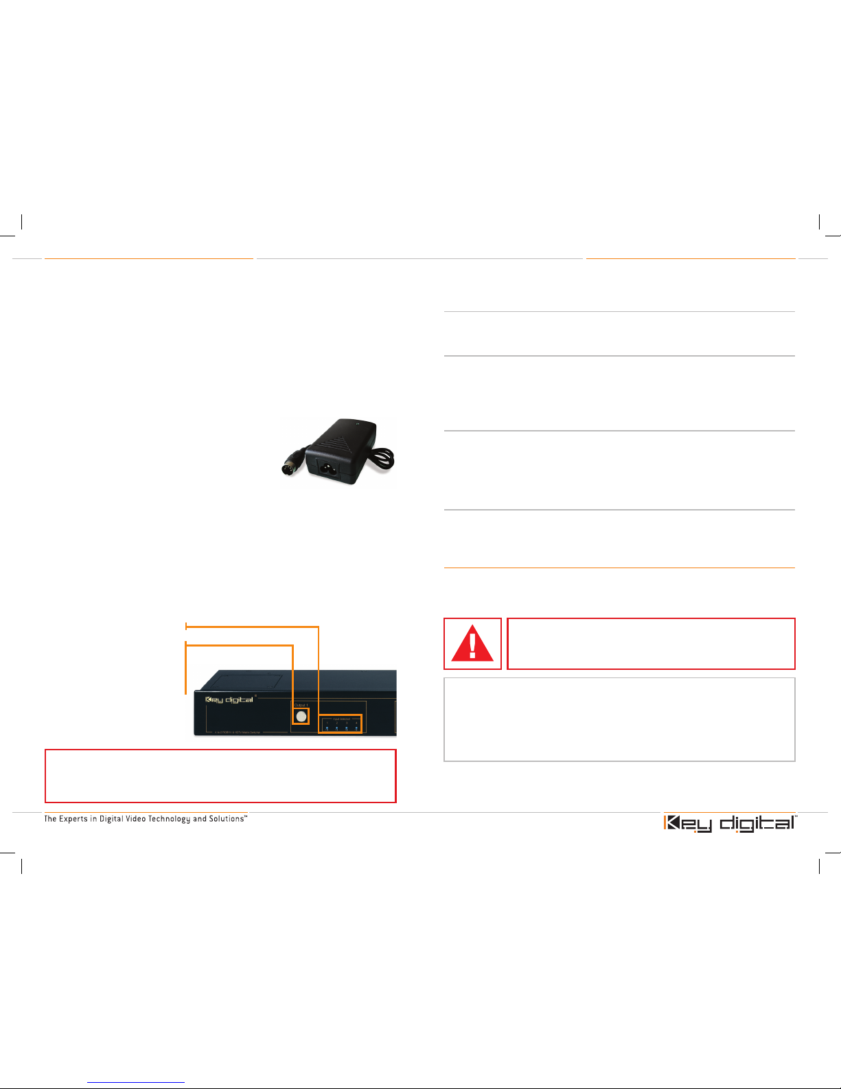
Power
Use ONLY the external power supply provided with the KDMSW4x2Pro unit. Use of any other power supply VOIDS the
Key Digital™ Warranty and may potentially damage the unit and
any associated equipment.
Connect the external power supply provided with the
KD-MSW4x2Pro to the jack on the rear panel of the unit.
Connect the power supply to an appropriate source of power, such as from a wall outlet.
Operation
Follow all manufacturer instructions for the safe and proper operation of the source and display
products that have been connected to the KD-MSW4x2Pro.
Using one of the convenient control options for the KD-MSW4x2Pro, separately select source
input 1, 2, 3, or 4 for output display 1, and source input 1, 2, 3, or 4 for output display 2.
Use the IR remote control with an extensive command and control capability.
See the description for the IR remote control provided later in this Operating Manual.
It is also possible under RS-232 control to allow any one of the four inputs to be switched and
distributed to both outputs [see the RS-232 Command List].
➔
»
»
➔
»
›
›
›
›
›
›
›
›
›
Additional Product Features
Several new features have been added to this generation of Key Digital™ switchers, called “Fade-toBlack” and “Video Mute.” Both of these features let the user switch like a pro, like in a live studio.
Fade-to-Black
The Fade-to-Black feature allows for switching between input/output combinations without the
usual visual signal noise, glitches, and sync roll that traditionally accompany switching between
video signals. The feature momentarily forces the video image to black as the desired source input
is selected for the chosen output. This feature is applied automatically and the fade time
interval is programmable via RS-232.
Video and Audio Mute
Video and Audio Mute enables the user to mute the audio and video signal (the display goes
to black) at the chosen output, using the RS-232 [see the RS-232 Command List] or IR remote
control. Using the IR remote control for Video and Audio Muting:
Activate Video & Audio Mute:
R1 ‡ output (1~2) ‡ up arrow
Deactivate Video & Audio Mute: R1 ‡ output (1~2) ‡ down arrow
Volume Control
Left and right analog stereo audio volume control feature provided for YPbPr mode (RGBHV video
mode does not support analog audio due to connector limitations).
FAT BOY SERIES EXPANSION
The KD-MSW4x2Pro is available as a stand-alone base unit, or pre-wired from Key Digital™ as
multiple Fat Boy units from the factory in an expanded output configuration. The KD-MSW4x2Pro
is available pre-wired from the factory in output expansion configurations that increment in steps of
two (at the output).
Operation of a base KD-MSW4x2Pro (configured as a 4x2 matrix switcher) is described in detail in
this Operating Manual.
IR Remote Sensor
Use this front-panel pushbutton to
select any of the up to four source
input devices to drive the display and
audio system wired to Output 1.
Press the button and cycle through
Input 1, 2, 3, and 4.
Repeat for Output 2 using the
appropriate Output 2 pushbutton and
LEDs for monitoring the input selection.
Input 1, 2, 3, and 4 LED indicators
Note:
Since the KD-MSW4x2Pro Matrix Switcher does NOT perform video
processing, the output video format is the same as the input video format. This
means that the video resolution is not changed and also that form of video is input to
the unit, for example Component Video, the output will be in exactly the same format.
CAUTION: If purchased as a Fat Boy expansion of the base 4x2
matrix switcher configuration, the multiple base units will come
pre-connected and tested from the factory. It is advised NOT to
disconnect or reconfigure any of these cables.
These Operating Instructions apply to the entire Key Digital™
Fat Boy Series line of KD-MSW4x2Pro HDTV Matrix Switchers:
KD-MSW4x2Pro . . . . . . . . . . 4 x 2 HDTV Matrix Switcher (single base unit, stand alone)
KD-MSW4x4Pro . . . . . . . . . . 4 x 4 HDTV Matrix Switcher (2 base units of 4x2 and Cable Kit)
KD-MSW4x6Pro . . . . . . . . . . 4 x 6 HDTV Matrix Switcher (3 base units of 4x2 and Cable Kit)
KD-MSW4x8Pro . . . . . . . . . . 4 x 8 HDTV Matrix Switcher (4 base units of 4x2 and Cable Kit)
MSW4x2Pro_Manual.indd 4-5 8/23/06 4:10:02 PM
KD-MSW4x2Pro Operating Instructions
Page 6
KD-MSW4x2Pro Operating Instructions
Page 7
Introduction
Thank you for purchasing the KD-MSW4x2Pro by Key Digital™, a state-of-the-art analog HDTV Fat
Boy Series 4-Input to 2-Output matrix switcher and distribution amplifier.
A base KD-MSW4x2Pro unit has 4 inputs to 2 outputs. Each of its two distinct outputs can be
used to drive two separate displays (and audio / surround sound systems), even the most exotic
high-end HDTV projectors on the market. One of up to four source input devices (like DVD players,
Set Top Boxes, etc.) can be independently and separately selected to drive each display. Switch
like a pro in the Studio, with the all-new “Fade-to-Black” and “Video Muting” features that eliminate
video “glitches” on the display when switching different inputs. If desired, the unit functions as a
distribution amplifier, simultaneously routing any single input to both outputs.
The KD-MSW4x2Pro is available pre-wired from the factory in output expansion configurations that
increment in steps of two (at the output).
The KD-MSW4x2Pro is perfectly suited for studio, home theater, custom
installation, retail, and in fact any and all analog HD and SD applications.
With analog video bandwidths up to 300 MHz, it handles all HD and
SD resolutions (50 and 60 Hz) including 1080p/60, with no degradation
in video or audio signal quality. Since the KD-MSW4x2Pro performs no
video or audio processing, the video and audio signals remain pure and
untouched, and hence the quality of the output signals is the same as
the quality of the input signals.
Typical source input devices that can be matrix switched with the KD-MSW4x2Pro include:
DVD players
Cable TV, satellite, and terrestrial Set Top Boxes (STBs)
Digital Video Recorders (DVRs)
D-VHS, S-VHS and VHS VCR’s
Electronic game boxes
Personal Computers (PCs)
›
›
›
›
›
›
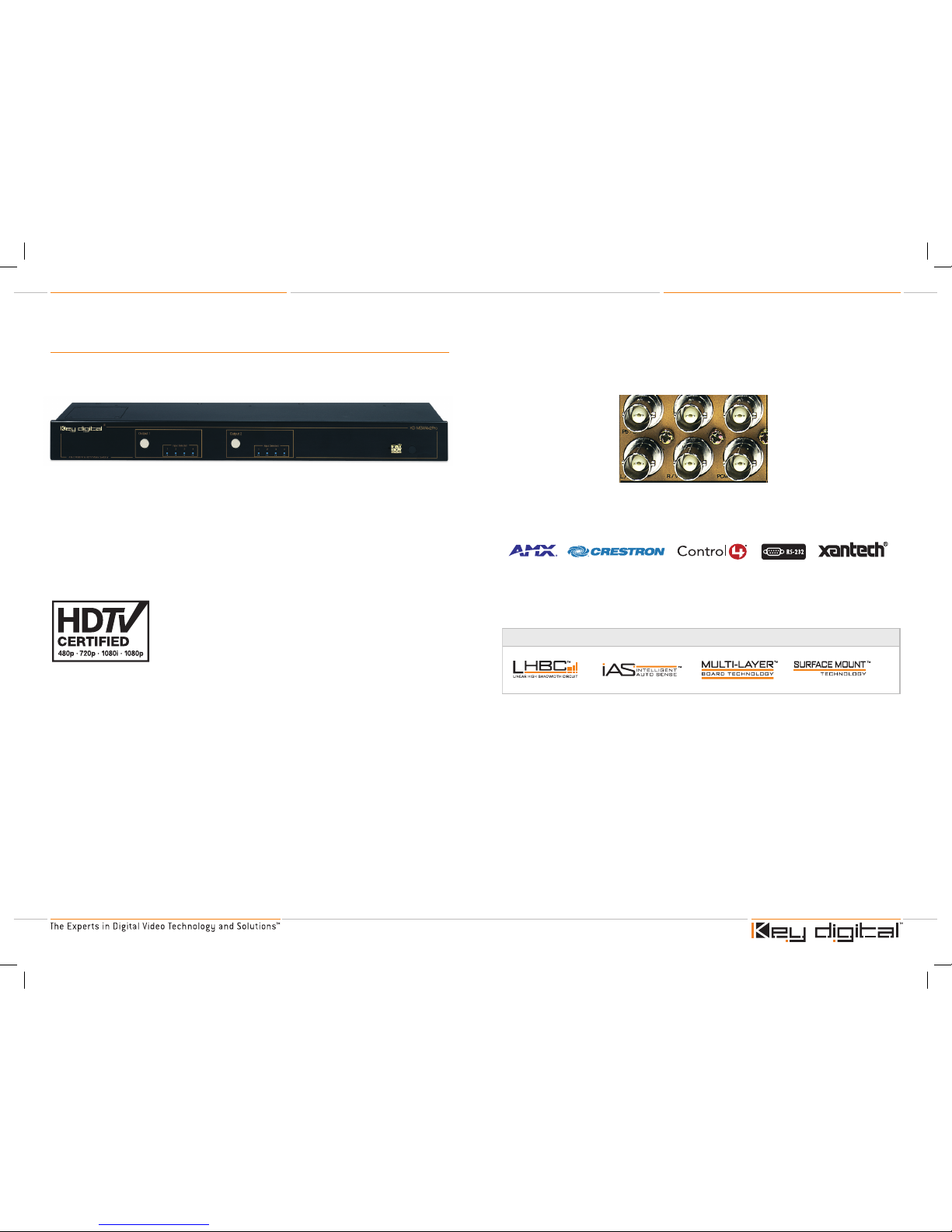
The KD-MSW4x2Pro uses BNC connectors for video and audio inputs and outputs, and supports
both component video (YPbPr) and RGBHV video formats. Along with the video, it concurrently
switches and distributes digital PCM, and analog stereo audio for YPbPr operation only.
The KD-MSW4x2Pro is simple to operate and control via front panel pushbuttons and LEDs,
IR (Infrared) remote control, IR Extender, wired IR, and is compatible via RS-232 with all control
systems.
The KD-MSW4x2Pro boasts a 300 MHz analog video bandwidth due in part to the following
custom and proprietary Key Digital™ technologies engineered into the product to ensure the
highest standard of picture quality:
Key Digital™ Exclusive Technologies Supported Technologies
MSW4x2Pro_Manual.indd 6-7 8/23/06 4:10:07 PM
KD-MSW4x2Pro Operating Instructions
Page 8
KD-MSW4x2Pro Operating Instructions
Page 9
Matrix Switching
The KD-MSW4x2Pro is a Matrix Switcher that accepts up to four inputs from source devices, and
can drive up to two displays.
A “Matrix Switcher” allows the user to select any input source device, and have it available on any
desired output (typically a display). For example, the user may choose to view a DVD player on the
display that is connected to Output 1, and view the satellite box on the display that is connected
to Output 2. A true matrix switcher, the KD-MSW4x2Pro provides the user with two degrees of
freedom:
The ability to select any particular input source device, namely the source devices connected to
Input 1, 2, 3, or 4
These input devices can be chosen separately for Output 1 and Output 2
Available as pre-wired output expansions: (4x2 base), 4x4, 4x6, and 4x8
Distribution Amplifier Application
If desired, the unit also acts as a distribution amplifier, simultaneously routing any single input to
both outputs.
›
›
›
Terminology
A/V
Audio/Video Used in reference to the audio and video signals typically
associated with a source device or display
B
Blue The "blue" video channel
BNC
connector
A BNC connector is professional studio-grade industry standard
video connector used for the video and audio inputs and outputs
of the KD-MSW4x2Pro
DVR
Digital Video Recorder For example, a TiVo box
G
Green The green video channel
H
Horizontal Horizontal video synchronizing signal
IR
Infrared IR, like the Infrared remote control. Simply point the front of an IR
remote control unit towards the IR sensor on the product to be
controlled.
L
Left The Left channel of an analog stereo pair, Left and Right
LED
LEDs (light-emitting diodes) are like small light bulbs that light up
to indicate a selection, and are used as status indicators
ms
Milliseconds Unit of time, in seconds/100; for example, the factory default for
Fade-to-Black video muting is 240 ms, which is equal to 240 x
10-3 (0.24) seconds
PCM,
digital
PCM
Pulse Code Modulation PCM is a sampling technique for digitizing analog signals,
especially audio signals. Used in this Operating Manual to refer to
digital audio.
R
Right Audio: The Right channel of an analog stereo pair, Left and Right
Red Video: The "red" video channel
RGBHV
"VGA"-like video Video signal wiring format using red (R), green (G), and blue (B)
signals. The horizontal (H) and vertical (V) signal s are used for
video synchronization. Sometimes the sync signals are embedded
in the green (G) channel, which frees-up the H&V connectors.
STB
Set Top Box For example, a Cable STB or Satellite STB
V
Vertical Vertical video synchronizing signal
VAC
Volts, AC Specifies the AC line voltage, such as nominally 120 volts in the US
YPbPr
Component Video Video signal wiring format using “luminance” (Y) and two color
signals (Pb and Pr). Typically the horizontal and vertical video
synchronizing signals are embedded in the Y channel.
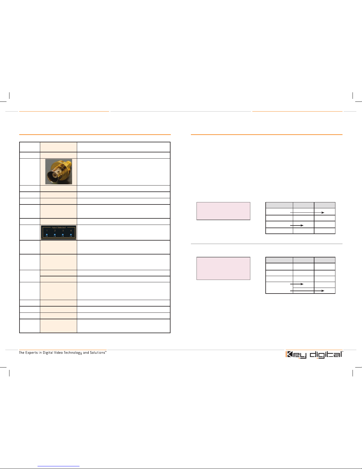
A "4x2" Matrix Switching Example:
Select Video Source #3 to Display 1
Select Source #1 to Display 2
Using a Matrix Switcher as a
Distribution Amplifier Example:
Select Video Source #4 to Display 1
Select Video Source #4 to Display 2
Video Source Display 1 Display 2
1 - Satellite STB
2 - DVR
3 - DVD Player
4 - Cable STB
Video Source Display 1 Display 2
1 - Satellite STB
2 - DVR
3 - DVD Player
4 - Cable STB
MSW4x2Pro_Manual.indd 8-9 8/23/06 4:10:09 PM
 Loading...