

Page 1
521 East 3rd Street, Mount Vernon, NY 10553
Phone :: 914.667.9700 Fax :: 914.668.8666
Web :: www.keydigital.com
KD-MSW4x2 Operating Instructions
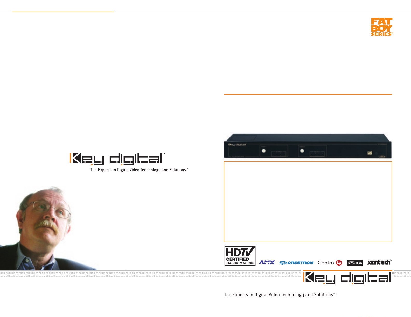
KD-MSW4x2
4 Inputs to 2 Outputs HDTV Matrix Switcher
Operating Instructions
Key Digital™, led by digital video pioneer Mike Tsinberg,
develops and manufactures high quality, cutting-edge
technology solutions for virtually all applications where
high quality video imaging is important. Key Digital™
is at the forefront of the video industry for Home
Theater Retailers, Custom Installers, System Integrators,
Broadcasters, Manufacturers, and Consumers. We
provide
know and help drive the technology, the industry, the
business, and all the latest up-and-coming standards.
But most of all, we know exactly what you need for your
unique application - the right solution.
total video system solutions because we
Rev 0 – July 2006
The Fat Boy Series KD-MSW4x2 by Key Digital™‚ is an analog HDTV 4-Input to 2-Output
matrix switcher and distribution amplifier. For each of the two displays connected to
its output, any of up to four source inputs can be separately and seamlessly switched
with the professional Fade-to-Black and Video Muting features. It supports both
component video (YPbPr) and RGBHV video formats; and S-Video and composite
video (CVBS), with adapters. Concurrent with the video, it switches and distributes
PCM coax digital audio, and analog stereo audio (no analog audio for RGBHV video).
With analog video bandwidths up to 300 MHz, the KD-MSW4x2 handles all HD and
SD resolutions (50 and 60 Hz) including 1080p/60, with no degradation in signal
quality. It is simple to operate and control via front panel pushbuttons with LEDs to
monitor the selections, IR remote control, IR Extender, wired IR, and is compatible via
RS-232 with all control systems.
Page 2
KD-MSW4x2 Operating Instructions
Page 2
KD-MSW4x2 Operating Instructions
Page 1
Table of Contents
Quick Setup Guide . . . . . . . . . . . . . . . . . . . . . . . . . . . . . . . . . . . . . . . . . . . . . . . . . . . . . . . . . . 1
Introduction . . . . . . . . . . . . . . . . . . . . . . . . . . . . . . . . . . . . . . . . . . . . . . . . . . . . . . . . . . . . . . . . 6
Terminology . . . . . . . . . . . . . . . . . . . . . . . . . . . . . . . . . . . . . . . . . . . . . . . . . . . . . . . . . . . . . . . . 8
Matrix Switching . . . . . . . . . . . . . . . . . . . . . . . . . . . . . . . . . . . . . . . . . . . . . . . . . . . . . . . . . . . . 6
What’s Included . . . . . . . . . . . . . . . . . . . . . . . . . . . . . . . . . . . . . . . . . . . . . . . . . . . . . . . . . . . . . 11
Quick Facts About the KD-MSW4x2 . . . . . . . . . . . . . . . . . . . . . . . . . . . . . . . . . . . . . . . . . . . . .12
Examine the Front and Rear Panels . . . . . . . . . . . . . . . . . . . . . . . . . . . . . . . . . . . . . . . . . . . . . .14
Connecting the Video and Audio Inputs and Outputs. . . . . . . . . . . . . . . . . . . . . . . . . . . . . . . . .16
Detailed Input/Output Descriptions . . . . . . . . . . . . . . . . . . . . . . . . . . . . . . . . . . . . . . . . . . . . . .19
Control Connections . . . . . . . . . . . . . . . . . . . . . . . . . . . . . . . . . . . . . . . . . . . . . . . . . . . . . . . . .21
Applying Power . . . . . . . . . . . . . . . . . . . . . . . . . . . . . . . . . . . . . . . . . . . . . . . . . . . . . . . . . . . . 23
Operation . . . . . . . . . . . . . . . . . . . . . . . . . . . . . . . . . . . . . . . . . . . . . . . . . . . . . . . . . . . . . . . . .24
IR Remote Control . . . . . . . . . . . . . . . . . . . . . . . . . . . . . . . . . . . . . . . . . . . . . . . . . . . . . . . . . . 26
RS-232 Commands and Protocol . . . . . . . . . . . . . . . . . . . . . . . . . . . . . . . . . . . . . . . . . . . . . . 29
Technical Specifications. . . . . . . . . . . . . . . . . . . . . . . . . . . . . . . . . . . . . . . . . . . . . . . . . . . . . . . 31
How to Contact Key Digital™ . . . . . . . . . . . . . . . . . . . . . . . . . . . . . . . . . . . . . . . . . . . . . . . . . . 35
Quick Setup Guide
If the user or installer is familiar with Video/Audio Matrix Switching and Distribution,
then the following Quick Setup Guide can be used as a shortcut.
to always follow all the detailed instructions provided in this entire Operating Manual
to properly hook-up, operate, and control the KD-MSW4x2 product.
Basics Facts About the KD-MSW4x2
The KD-MSW4x2 is a 4-Input to 2-Output video and audio matrix switcher and distribution
amplifier. Each of its two distinct outputs can be used to drive two separate displays and audio/
surround sound systems. One of up to four source input devices can be independently and
separately selected to drive each of the two displays and audio systems. The product provides
professional-grade switching, with the Fade-to-Black and Video Mute features, preventing image
glitches when switching between sources.
Typical source input devices that can be matrix switched with the KD-MSW4x2 include:
DVD players and changers
›
Cable TV, satellite, and terrestrial Set Top Boxes (STBs)
›
Digital Video Recorders (DVRs)
›
D-VHS, S-VHS and VHS VCR’s
›
Electronic game boxes
›
Personal Computers (PCs)
›
The KD-MSW4x2 handles all HD and SD resolutions, and is compatible with all standard analog
video signal formats, including:
1080p, 1080i, 720p, 576p, 576i, 540p, 480p, 480i
›
50 Hz or 60 Hz refresh rates
›
The KD-MSW4x2 performs no video or audio processing, and supports video bandwidths up to
300 MHz. Its output stage drives high-quality, equal-length video cables up to 300’ or more. The
output formats and resolutions are identical to those at the input to the unit.
The KD-MSW4x2 uses RCA jacks for video and audio inputs and outputs, and supports both
component video (YPbPr) and RGBHV video formats; as well as S-Video and composite video
(CVBS), with adapters. Along with the video, it concurrently switches and distributes PCM coax
digital audio, and analog stereo audio (for YPbPr operation only).
It is recommended
© 2006 Key Digital, Inc. All rights reserved.
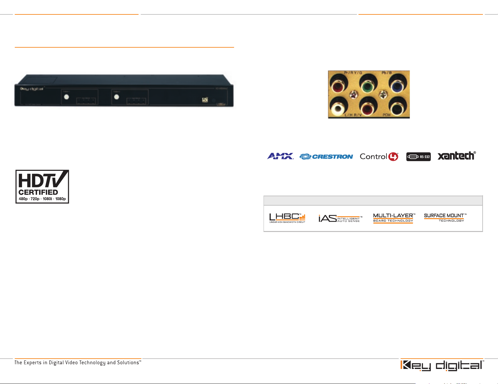
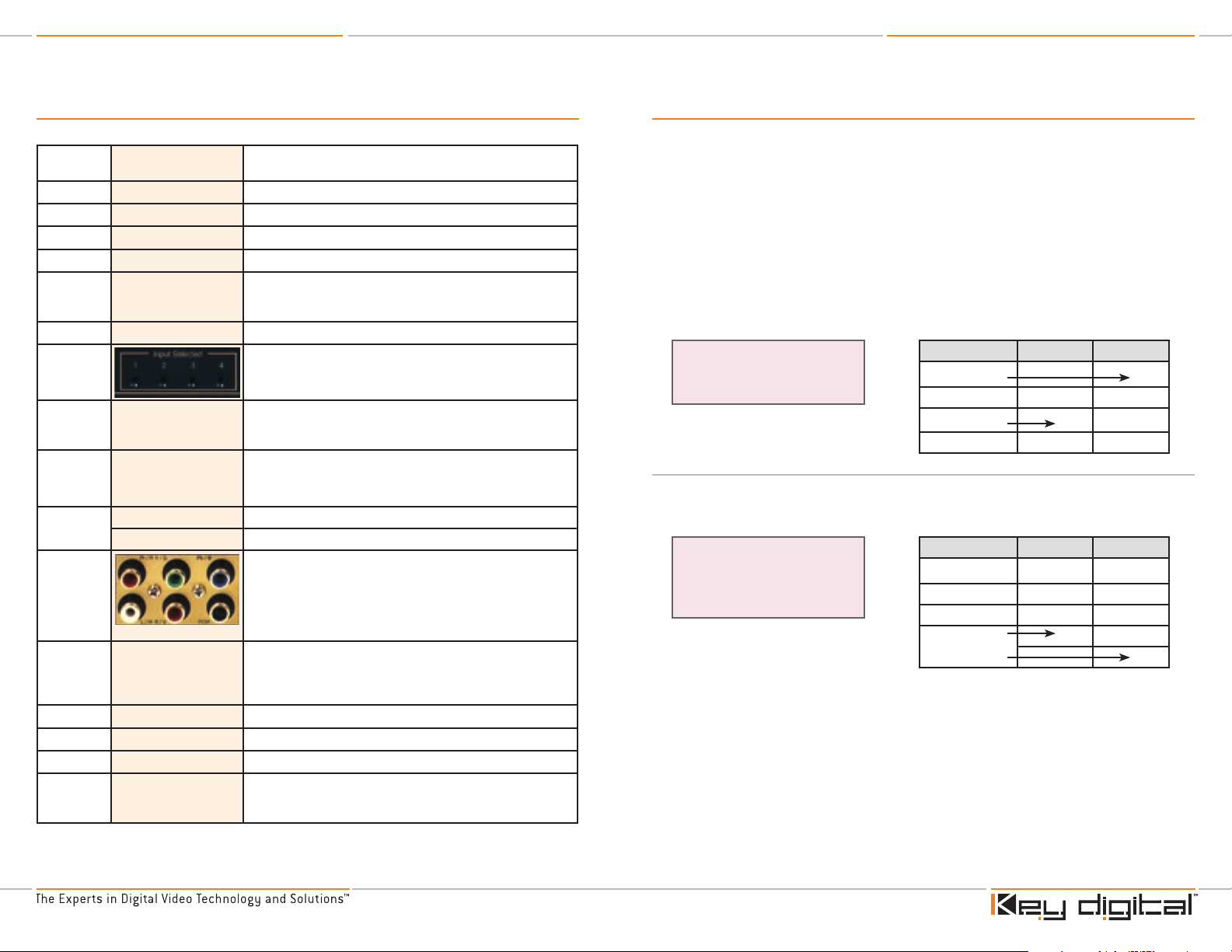
The KD-MSW4x2 has four (4) Input Ports and two (2) Output Ports. Each Input Port and Output
Port is comprised of six (6) color-coded RCA jacks:
3 analog video connectors (YPbPr or RGB, shared as Pr/R Y/G Pb/B)
›
2 analog audio connectors (Left and Right stereo pairs)
›
The analog audio input/output connectors also serve as the horizontal (H) and vertical (V) sync
›
for RGBHV signals
1 PCM digital coax audio connector
›
Page 3

KD-MSW4x2 Operating Instructions
Page 2
KD-MSW4x2 Operating Instructions
Page 3
Video
Audio
Component Video Applications
Inputs and Outputs
RGBHV Video Applications
Inputs and Outputs
Pr Y Pb
Left (L) Right (R) Digital
PCM
R G B
H V Digital
PCM
Component Video
RGBHV Video
Analog
Stereo
Audio
Digital
Audio
Digital
Audio
If video sync is
on Green (G), then
Analog Stereo Audio
is also supported
here in place of H&V
Inputs
Outputs
Power Supply
Wired IR
IR Extender
RS-232
1 2 1 23 4
Pushbutton to Select Input
Input Selected LEDs
IR Remote Sensor
Front and Rear Panels
Typical Input/Output Port
Quick Installation
CAUTION: Do not connect the external supply (provided) to
the back of the KD-MSW4x2 unit until ALL of your video and
audio connections are completed.
For proper operation of the high quality electrical circuits in the KD-MSW4x2 unit, do
NOT "daisy chain" inputs:
Each input of the KD-MSW4x2 has its own 75 Ω termination
➔
Do NOT feel a source to multiple KD-MSW4x2 inputs without proper
➔
distribution equipment
Connect up to four source devices to the Input Ports 1 - 4 on the rear panel
›
of the KD-MSW4x2 unit.
Connect two displays to the Output Ports 1 and 2 on the rear panel
›
of the KD-MSW4x2 unit.
Input/Output Ports and Formats
The output format = the format of the selected input source
›
Each Port supports:
›
YPbPr component video, analog stereo left and right audio, and digital PCM audio
➔
RGBHV video and digital PCM audio
➔
RGB video with sync on the green channel, analog stereo left and right audio, and digital PCM
➔
audio
S-Video and composite video (CVBS), with adapters
➔
Each connector can accommodate various signals, on a shared basis:
›
Red Connector: Pr/R
➔
Pr label is for component video
»
R label is for the red channel for RGBHV video
»
Green Connector: Y/G
➔
Y label is for component video
»
G label is for the green channel for RGBHV video
»
Blue Connector: Pb/B
➔
Pb label is for component video
»
B label is for the blue channel for RGBHV video
»
White Connector: L/H
➔
L label is for the left analog stereo audio channel
»
H label is for the horizontal sync for RGBHV video
»
Red Connector: R/V (Right analog stereo audio, or vertical sync for RGBHV video)
➔
R label is for the right analog stereo audio channel
»
Page 4
KD-MSW4x2 Operating Instructions
Page 4
KD-MSW4x2 Operating Instructions
Page 5
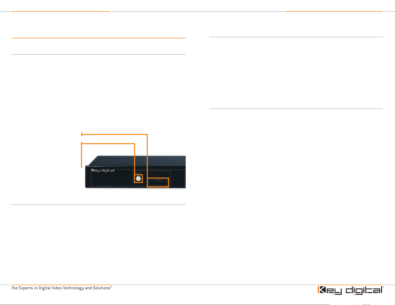
IR Remote Sensor
Use this front-panel pushbutton to
select any of the up to four source
input devices to drive the display and
audio system wired to Output 1.
Press the button and cycle through
Input 1, 2, 3, and 4.
Repeat for Output 2 using the
appropriate Output 2 pushbutton and
LEDs for monitoring the input selection.
Input 1, 2, 3, and 4 LED indicators
V label is for the vertical sync for RGBHV video
»
Black Connector: PCM
➔
For PCM digital coax audio
»
Control Connections
Decide how the KD-MSW4x2 will be controlled
›
If using an IR (Infrared) Extender, the wired IR, or an external Control System (via the RS-232 port
›
on the KD-MSW4x2), make the appropriate connections
Power
Use ONLY the external power supply provided with the KD-MSW4x2 unit. Use of any other
›
power supply VOIDS the Key Digital™ Warranty and may
potentially damage the unit and any associated equipment.
Connect the external power supply provided with the
›
KD-MSW4x2 to the jack on the rear panel of the unit.
Connect the power supply to an appropriate source of power,
›
such as from a wall outlet.
Operation
Follow all manufacturer instructions for the safe and proper operation of the source and display
›
products that have been connected to the KD-MSW4x2.
Using one of the convenient control options for the KD-MSW4x2, separately select source input
›
1, 2, 3, or 4 for output display 1, and source input 1, 2, 3, or 4 for output display 2.
Use the IR remote control with an extensive command and control capability.
›
See the description for the IR remote control provided later in this Operating Manual.
It is also possible under RS-232 control to allow any one of the four inputs to be switched and
›
distributed to both outputs [see the RS-232 Command List].
Additional Product Features
Several new features have been added to this generation of Key Digital™ switchers, called “Fade-toBlack” and “Video Mute.” Both of these features let the user switch like a pro, like in a live studio.
Fade-to-Black
The Fade-to-Black feature allows for switching between input/output combinations without the
usual visual signal noise, glitches, and sync roll that traditionally accompany switching between
video signals. The feature momentarily forces the video image to black as the desired source input
is selected for the chosen output. This feature is applied automatically and the fade time
interval is programmable via RS-232.
Video and Audio Mute
Video and Audio Mute enables the user to mute the audio and video signal (the display goes
to black) at the chosen output, using the RS-232 [see the RS-232 Command List] or IR remote
control. Using the IR remote control for Video and Audio Muting:
Activate Video & Audio Mute:
Deactivate Video & Audio Mute: R1 ‡ output (1~2) ‡ down arrow
R1 ‡ output (1~2) ‡ up arrow
Note: Since the KD-MSW4x2 Matrix Switcher does NOT perform video processing,
the output video format is the same as the input video format. This means that the
video resolution is not changed and also that form of video is input to the unit, for
example Component Video, the output will be in exactly the same format.
Page 5
KD-MSW4x2 Operating Instructions
Page 6
KD-MSW4x2 Operating Instructions
Page 7
Key Digital™ Exclusive Technologies Supported Technologies
Introduction
Thank you for purchasing the KD-MSW4x2 by Key Digital™, a state-of-the-art analog HDTV Fat Boy
Series 4-Input to 2-Output matrix switcher and distribution amplifier.
Each of its two distinct outputs can be used to drive two separate displays (and audio / surround
sound systems), even the most exotic high-end HDT V projectors on the market. One of up to four
source input devices (like DVD players, Set Top Boxes, etc.) can be independently and separately
selected to drive each display. Switch like a pro in the Studio, with the all-new “Fade-to-Black”
and “Video Muting” features that eliminate video “glitches” on the display when switching different
inputs. If desired, the unit functions as a distribution amplifier, simultaneously routing any single
input to both outputs. Also, the product is expandable.
The KD-MSW4x2 uses RCA jacks for video and audio inputs and outputs, and supports both
component video (YPbPr) and RGBHV video formats. Along with the video, it concurrently switches
and distributes digital PCM, and analog stereo audio for YPbPr operation only.
The KD-MSW4x2 is simple to operate and control via front panel pushbuttons and LEDs, IR
(Infrared) remote control, IR Extender, wired IR, and is compatible via RS-232 with all control
systems.
The KD-MSW4x2 is perfectly suited for studio, home theater, custom
installation, retail, and in fact any and all analog HD and SD applications.
With analog video bandwidths up to 300 MHz, it handles all HD and
SD resolutions (50 and 60 Hz) including 1080p/60, with no degradation
in video or audio signal quality. Since the KD-MSW4x2 performs no
video or audio processing, the video and audio signals remain pure and
untouched, and hence the quality of the output signals is the same as
the quality of the input signals.
Typical source input devices that can be matrix switched with the KD-MSW4x2 include:
DVD players
›
Cable TV, satellite, and terrestrial Set Top Boxes (STBs)
›
Digital Video Recorders (DVRs)
›
D-VHS, S-VHS and VHS VCR’s
›
Electronic game boxes
›
Personal Computers (PCs)
›
The KD-MSW4x2 boasts a 300 MHz analog video bandwidth due in part to the following custom
and proprietary Key Digital™ technologies engineered into the product to ensure the highest
standard of picture quality:
Page 6
KD-MSW4x2 Operating Instructions
Page 8
KD-MSW4x2 Operating Instructions
Page 9
Terminology
A/V
B
DVR
G
H
IR
L
LED
ms
PCM,
digital
PCM
R
RCA jack
RGBHV
STB
V
VAC
YPbPr
Audio/Video Used in reference to the audio and video signals typically
Blue The "blue" video channel
Digital Video Recorder For example, a TiVo box
Green The green video channel
Horizontal Horizontal video synchronizing signal
Infrared IR, like the Infrared remote control. Simply point the front of an IR
Left The Left channel of an analog stereo pair, Left and Right
LEDs (light-emitting diodes) are like small light bulbs that light up
Milliseconds Unit of time, in seconds/100; for example, the factory default for
Pulse Code Modulation PCM is a sampling technique for digitizing analog signals,
Right Audio: The Right channel of an analog stereo pair, Left and Right
Red Video: The "red" video channel
An RCA jack or what was called a “phono plug” is an industry
"VGA"-like video Video signal wiring format using red (R), green (G), and blue (B)
Set Top Box For example, a Cable STB or Satellite STB
Vertical Vertical video synchronizing signal
Volts, AC Specifies the AC line voltage, such as nominally 120 volts in the US
Component Video Video signal wiring format using “luminance” (Y) and two color
associated with a source device or display
remote control unit towards the IR sensor on the product to be
controlled.
to indicate a selection, and are used as status indicators.
Fade-to-Black video muting is 240 ms, which is equal to 240 x
10-3 (0.24) seconds
especially audio signals. Used in this Operating Manual to refer to
digital audio.
standard audio connector used for the audio inputs and outputs
of the KD-MSW4x2. The black connector jack [ “PCM”] is used
for the digital audio formats. Analog stereo audio uses both jacks,
where white = the left channel [“L”], and red = the right channel
[“R”]. The video inputs and outputs also use RCA connectors.
signals. The horizontal (H) and vertical (V) signals are used for
video synchronization. Sometimes the sync signals are embedded
in the green (G) channel, which frees-up the H&V connectors.
signals (Pb and Pr). Typically the horizontal and vertical video
synchronizing signals are embedded in the Y channel.
Matrix Switching
The KD-MSW4x2 is a Matrix Switcher that accepts up to four inputs from source devices, and can
drive up to two displays.
A “Matrix Switcher” allows the user to select any input source device, and have it available on any
desired output (typically a display). For example, the user may choose to view a DVD player on the
display that is connected to Output 1, and view the satellite box on the display that is connected to
Output 2. A true matrix switcher, the KD-MSW4x2 provides the user with two degrees of freedom:
The ability to select any particular input source device, namely the source devices connected to
›
Input 1, 2, 3, or 4
These input devices can be chosen separately for Output 1 and Output 2
›
A "4x2" Matrix Switching Example:
Select Video Source #3 to Display 1
Select Source #1 to Display 2
Distribution Amplifier Application
If desired, the unit also acts as a distribution amplifier, simultaneously routing any single input to
both outputs.
Using a Matrix Switcher as a
Distribution Amplifier Example:
Select Video Source #4 to Display 1
Select Video Source #4 to Display 2
Video Source Display 1 Display 2
1 - Satellite STB
2 - DVR
3 - DVD Player
4 - Cable STB
Video Source Display 1 Display 2
1 - Satellite STB
2 - DVR
3 - DVD Player
4 - Cable STB
Page 7

KD-MSW4x2 Operating Instructions
Page 10
KD-MSW4x2 Operating Instructions
Page 11
Pushbutton to Select Input
Input Selected LEDs
IR Remote Sensor
Convenient front-panel LED indicatiors display the selecte input,
for each of the two outputs
The KD-MSW4x2 allows the matrix-switched input/output combinations to be configured via the
front panel pushbuttons, with the user’s input selection displayed by front-panel LED indicators for
each of the two outputs. Switching can be accomplished conveniently in any of three ways:
Manually, using the front panel pushbuttons that cycle through the four inputs
›
Remotely, using the supplied IR remote control
›
A rear-panel IR Extender is also provided
➔
A rear-panel wired IR is also provided
➔
Using the RS-232 control, the unit is compatible with all Control Systems
›
Regardless of how the unit is controlled, the user’s input selection is confirmed on the front-panel
LED indicators for each of the two outputs.
What’s Included
The following contents are provided in the carton:
One KD-MSW4x2 unit
1.
Separate external 6-Volt power supply
2.
IR remote control with batteries included
3.
Operating Manual (Instructions)
4.
Warranty card
5.
CAUTION: When installing the KD-MSW4x2 unit, make all
video and audio hookups and connections before plugging in
the external power supply (provided). Do NOT apply power to
the unit until all video and audio connections have been made
to the KD-MSW4x2 unit from the “source” devices and to the
output displays and/or audio systems.
Use only the external power supply provided with the
KD-MSW4x2 unit or you VOID the Key Digital™ Warranty and
may potentially damage to the unit and associated equipment.
The KD-MSW4x2 Operating Manual
The successful system integration and operation of the KD-MSW4x2 4-to-2 HDT V Matrix Switcher
is very important to us at Key Digital™. Please follow all of the instructions provided here to ensure
proper operation of the product. Contact Key Digital™ immediately if any difficulties are incurred (see
the end of this Operating Manual for contact information).
Page 8
KD-MSW4x2 Operating Instructions
Page 12
KD-MSW4x2 Operating Instructions
Page 13
Quick Facts about the KD-MSW4x2
The KD-MSW4x2 by Key Digital‚ is an analog HDTV Fat Boy Series 4-Input to 2-Output matrix
switcher and distribution amplifier. It is perfectly suited for studio, home theater, custom installation,
retail, and in fact any and all analog HD and SD applications.
Typical Configuration: Analog HDTV
Connect four sources to the input of the KD-MSW4x2 (for example: a DVD player, Cable Set Top
›
Box, Satellite Set Top Box, and PC)
Connect two displays to the output of the KD-MSW4x2 (for example, a Plasma and an LCD
›
display)
Connect the audio outputs of the KD-MSW4x2 to surround sound or other audio systems, or to
›
the speakers in the displays
It is expandable
›
Matrix Switcher and Distribution Amplifier
For each of the two KD-MSW4x2 outputs that can be used to drive separate displays, one of the
›
four source inputs can be independently selected
For example, it’s as easy as 1, 2, 3:
›
Connect the video and audio from a DVD player, Cable Set Top Box, Satellite Set Top Box, and
1.
PC to the inputs of the KD-MSW4x2
Connect the video (and audio) outputs of the KD-MSW4x2 to two displays, a Plasma and an
2.
LCD (the audio may be separately connected to surround sound or other audio systems, or to
the speakers in the displays)
Use any of the control options on the KD-MSW4x2 to select the Cable Box to drive the Plasma
3.
and the DVD player to drive the LCD, or any other combination
It is also possible under RS-232 control to allow any one of the four inputs to be switched and
›
distributed to both outputs.
Professional Switching Features
Fade-to-Black: allows for switching between input/output combinations without the usual visual
›
signal noise, glitches, and sync roll that traditionally accompany switching between video signals
The feature momentarily forces the video image to black as the desired source input is
➔
selected for the chosen output
This feature is applied automatically
➔
Fade time inter val is programmable via the RS-232 [see the RS-232 Command List], and is
➔
equivalent to a “Video Mute” to force the video to black during switching
Formats
Video:
›
Supports component video (YPbPr) and RGBHV video formats
➔
Supports S-Video and composite video (CVBS), with adapters
➔
Output stage drives high-quality, equal-length video cables up to 300’ or more
➔
Audio:
›
Along with the video, the KD-MSW4x2 switches and distributes digital PCM, and analog
➔
stereo audio:
Digital PCM is available with either YPbPr or RGBHV video
›
Analog stereo audio is available with YPbPr video but not RGBHV video, unless the sync is on
›
green (G) channel
Uses RCA jacks for video and audio inputs and outputs
›
Resolution
Handles all HD and SD resolutions (50 and 60 Hz) including 1080p/60
›
Supports analog video bandwidths up to 300 MHz
›
The KD-MSW4x2 performs no video or audio processing:
›
The video and audio signals remain pure and untouched
➔
Introduces no degradation in video or audio signal quality
➔
Control
Simple to operate, control, and monitor via:
›
Front panel pushbuttons and LEDs
➔
IR remote control, with extensive commands and control
➔
IR Extender
➔
Wired IR
➔
All control systems (with RS-232)
➔
Video Mute: enables the user to mute the video signal (the display goes to black) at the chosen
›
output
Page 9

KD-MSW4x2 Operating Instructions
Page 14
KD-MSW4x2 Operating Instructions
Page 15
Inputs
Outputs
Power Supply
Wired IR
IR Extender
RS-232
1 2 1 23 4
Pushbutton to Select Input
Input Selected LEDs
IR Remote Sensor
Examine the Front and Rear Panels
Become familiar with the front and rear panels of the KD-MSW4x2 unit.
Front Panel
The front panel contains the pushbutton selection switches and associated input select LED
indicators for Output 1 and Output 2:
For each output, select source Input 1, 2, 3, or 4
›
The IR remote control sensor is also located on the front panel:
A clear line-of-site to the sensor is required when operating the IR remote control provided with
›
the unit
Each connector can accommodate various signals, on a shared basis:
›
Red Connector: Pr/R
➔
Pr label is for component video
»
R label is for the red channel for RGBHV video
»
Green Connector: Y/G
➔
Y label is for component video
»
G label is for the green channel for RGBHV video
»
Blue Connector: Pb/B
➔
Pb label is for component video
»
B label is for the blue channel for RGBHV video
»
White Connector: L/H
➔
L label is for the left analog stereo audio channel
»
H label is for the horizontal sync for RGBHV video
»
Red Connector: R/V (Right analog stereo audio, or vertical sync for RGBHV video)
➔
R label is for the right analog stereo audio channel
»
V label is for the vertical sync for RGBHV video
»
Black Connector: PCM
➔
For PCM digital coax audio
»
The following connectors are also provided on the rear panel:
›
RS-232 Connector
➔
IR Extender sensor
➔
Wired IR serial port
➔
External power supply connector
➔
Rear Panel
The rear panel contains 4 Input Ports and 2 Output Ports:
Each Port is comprised of 6 color-coded RCA connectors
›
Each Port can support:
›
YPbPr component video, analog stereo left and right audio, and
➔
digital PCM audio
RGBHV video and digital PCM audio
➔
RGB video with sync on the green channel, analog stereo left and right audio,
➔
and digital PCM audio
Page 10

KD-MSW4x2 Operating Instructions
Page 16
KD-MSW4x2 Operating Instructions
Page 17
Video
Audio
Component Video Applications
Inputs and Outputs
RGBHV Video Applications
Inputs and Outputs
Pr Y Pb
Left (L) Right (R) Digital
PCM
R G B
H V Digital
PCM
Component Video
RGBHV Video
Analog
Stereo
Audio
Digital
Audio
Digital
Audio
If video sync is
on Green (G), then
Analog Stereo Audio
is also supported
here in place of H&V
Connecting the Video and Audio Inputs and Outputs
Decide on a safe location to place or mount the KD-MSW4x2. Provide enough space for sufficient
airflow and ventilation, especially if the unit is left “On” most of the time.
Do not connect the external supply (provided) to the back
of the KD-MSW4x2 unit until ALL of your video and audio
connections are completed.
Test for proper operation of the unit, interconnections, and cables before final
installation of cables behind walls or ceilings. The output stage of the KD-MSW4x2
is capable of driving high-quality, equal-length video cables up to 300’ or more.
Connecting A/V Equipment
Connecting A/V equipment to the KD-MSW4x2 HDT V Matrix Switcher is straightforward and easily
accomplished via the ergonomic rear panel connector array. Because not all consumer equipment
marketed today uses RCA connector interfaces, it may be necessary to employ adapter plugs
and/or cable assemblies to interface these various devices to the unit.
The video signal format must be considered when making connections to the KD-MSW4x2 unit.
Simply match the A/V device’s output (namely YPbPr “Component” or RGBHV “VGA” video) to a
similar video signal output configuration on the KD-MSW4x2. S-Video and/or composite video
may also be interfaced with the unit, using appropriate adapters available separately.
The same consideration applies to the audio interfaces. Both analog and digital audio output
options are provided on the KD-MSW4x2. Use the appropriate format, such as analog audio when
connecting directly to the audio inputs of a video monitor; or digital audio, when connecting instead
to an A/V receiver having coaxial digital (PCM) interfaces for decoding surround sound signals.
CAUTION: The output stage of the KD-MSW4x2 can drive high-quality
length video cables up to 300' or more. Be sure to use high-quality
cables like those available through Key Digital™. Always ensure cables
for each output are equal in length for each video component.
CAUTION: For proper operation of the high quality electrical circuits in
the KD-MSW4x2 unit, do NOT "daisy chain" inputs:
Each input of the KD-MSW4x2 has its own 75 Ω termination
➔
Do NOT feel a source to multiple KD-MSW4x2 inputs without
➔
proper distribution equipment
CAUTION: Connecting digital PCM audio signals directly to the analog
audio input of a TV monitor, display, or other device can result in
severe damage to its speakers.
The 4 Input Ports and the 2 Output Ports are Configured Identically
The Port configurations are the same for the 4 Input Ports and the 2 Output Ports. Each Port is
comprised of six (6) color-coded RCA connectors:
Connect up to four video and audio sources to the RCA jack Input Ports of the KD-MSW4x2.
›
Digital PCM audio is available with either YPbPr or RGBHV video
➔
Analog stereo audio is available with YPbPr video but not RGBHV video, unless the sync is on
➔
green (G)
Connect up to two displays to the RCA jack Output Ports of the KD-MSW4x2. The audio
›
outputs from the product can be connected to the audio inputs of the display, or separate
surround sound or other audio systems.
Note: The left and right analog stereo audio interfaces also double as the horizontal and vertical sync signals
(respectively) for the RGB video interface.
Page 11

KD-MSW4x2 Operating Instructions
Page 18
KD-MSW4x2 Operating Instructions
Page 19
Audio
Audi
o
Audi
o
Audi
o
Satellite Box
Cable Box
DVD Player
TiVo
KD-MSW4x2
Plasma/LCD
*All Component sources can be
substituted with RGBHV sources
Componen
t
Componen
t
Componen
t
Componen
t
Componen
t
Audi
o
RS232 Control
Wired IR
Optical IR
Optical IR
Plasma/LCD
Componen
t
Audio
Zo
ne
2
Zo
ne
1
Key Digital® Exclusive Technologies Supported Technologies
Typical Application Example for the KD-MSW4x2 HDTV Matrix Switcher
Detailed Input/Output Descriptions
The interconnection of video and audio equipment in the various formats supported by the KDMSW4x2 unit is described here in detail. This section is particularly useful if some source devices
or displays are only available with S-Video or Component Video formats
For proper operation of the high quality electrical circuits in the KD-MSW4x2 unit,
do NOT “daisy chain” inputs:
Each input of the KD-MSW4x2 has its own 75 Ω termination
➔
Do NOT feed a source to multiple KD-MSW4x2 inputs without proper
➔
distribution equipment
High-quality Component Video (YPbPr) and “VGA” (RGBHV) Source Equipment
Some source equipment may have an analog video output that is called Component Video, a
3-wire video format with the video signals labeled YPbPr. Another common analog video output
format is RGB (like the “VGA” outputs on a computer), which typically has separate H&V sync
signals. The KD-MSW4x2 HDTV Matrix Switcher is the perfect choice for switching Component
Video and RGBHV Video source devices to displays with analog inputs.
Example: Connecting a digital TV set-top receiver with Component Video three-wire YPbPr or
“VGA” five-wire RGBHV video Outputs to the KD-MSW4x2 HDT V Matrix Switcher Inputs
YPbPr Component Video
Connect the three-wire green, blue and red YPbPr cables from the set-top receiver of choice, to the
green, blue, and red color-coded connectors of any one of the four Input Ports on the rear of the
KD-MSW4x2 unit. Connect the white and red analog stereo audio cables from the set-top receiver
to the white and red connectors of the same Input Port of the KD-MSW4x2 unit. If a digital audio
coaxial output is available on the set-top receiver, it can then connect to the black-coded PCM
connector on the KD-MSW4x2 unit.
Connect the green, blue, and red connectors from Output Ports 1 or 2 on the KD-MSW4x2 unit
to the corresponding component video jacks on the desired display. Connect the white and red
analog audio jacks from the same Output Port to the corresponding white and red audio jacks on
the audio system (which may be built into the display). If digital PCM audio is desired from the settop receiver, connect a cable from the black connector in the same chosen Output Port to the A/V
receiver's coaxial digital audio input.
CAUTION: To prevent damage to equipment, do NOT connect the KD-MSW4x2
digital PCM audio outputs to any analog audio inputs on a display or audio system!
Page 12

KD-MSW4x2 Operating Instructions
Page 20
KD-MSW4x2 Operating Instructions
Page 21
RGBHV
If the set-top receiver of choice employs RGBHV outputs, a 15-pin “breakout” adapter cable may
needed to implement the interface. In this instance connect the red, green and blue connectors
from this adapter cable to the red, green and blue connectors, again on any one of the four Input
Ports of the KD-MSW4x2 unit. Connect the black and yellow wires from the breakout cable to the
white (H) and red (V) connectors of the same Input Port of the KD-MSW4x2 unit.
Connect the RGBHV video signals from Output Ports 1 or 2 on the KD-MSW4x2 unit to the
corresponding RGBHV video jacks on the desired display. A second 15-pin breakout cable may be
required for certain sets.
It is not possible to use analog audio switching when in RGB video applications because the H&V
sync signals required for the RGB format occupy the port connectors typically used for the audio
signals. Digital PCM may be used for this application, as described above.
This same connection procedure described above applies to any other peripheral device
that one may wish to interface with a desired display medium, including DVD players and
game consoles.
Lower-quality S-Video (two-wire) or Composite Video (CVBS) Source Equipment
S-Video
For S-Video applications, a “breakout” adapter cable is required to connect a source device to the
KD-MSW4x2 unit. This cable is equipped with an S-Video (DIN) plug at one end and a pair of RCA
plugs at the other connected to white and yellow conductors. Connect the white (Y) conductor to
the green RCA connector of the selected Input Port, and connect the yellow (C) conductor to either
the blue or red RCA connector in the same input field. Connect the white and red analog stereo
audio connectors of the source device to the white and red connectors in the same Input Port of
the KD-MSW4x2 unit.
Connect the green RCA connector from Output Ports 1 or 2 on the KD-MSW4x2 unit to the white
(Y) conductor of a second S-video adapter cable. Connect the blue or red connector to the yellow
(C) conductor. Plug the other end of the adapter cable into the TV or monitor's S-video input.
Connect the white and red analog stereo audio cable connectors to the white and red connectors
of the same Output Port on the KD-MSW4x2 unit. Connect the other end of the audio cable pair to
the white and red analog audio input of the display.
Control Connections
Decide how the KD-MSW4x2 will be controlled. If using an IR (Infrared) Extender, the wired IR,
or an external Control System (via the RS-232 port on the KD-MSW4x2), make the appropriate
connections now.
RS-232
The KD-MSW4x2 HDTV Matrix Switcher is compatible with all Control Systems. Use the D-sub
9-pin connecter on the rear panel and an appropriate cable to attach the unit to an external Control
System. An RS-232 cable is not supplied* with the base KD-MSW4x2 unit. Carefully insert your
own RS-232 cable (9-pin) to the back of the unit, and to an appropriate PC or Control System.
Composite Video (CVBS) Connection
Connect the Composite Video connector (yellow) from a VCR or other source device to the green
RCA connector in the selected Input Port on the KD-MSW4x2 unit. Connect another composite
video cable from the green RCA connector from Output Ports 1 or 2 on the KD-MSW4x2 unit to the
TV or video monitor. Follow the instructions above for connecting analog audio.
If applicable, Key Digital™‚ Fat Boy KD-MSW4x2 expansion units come preconfigured from the factory with their own
RS-232 cable
Page 13

KD-MSW4x2 Operating Instructions
Page 22
KD-MSW4x2 Operating Instructions
Page 23
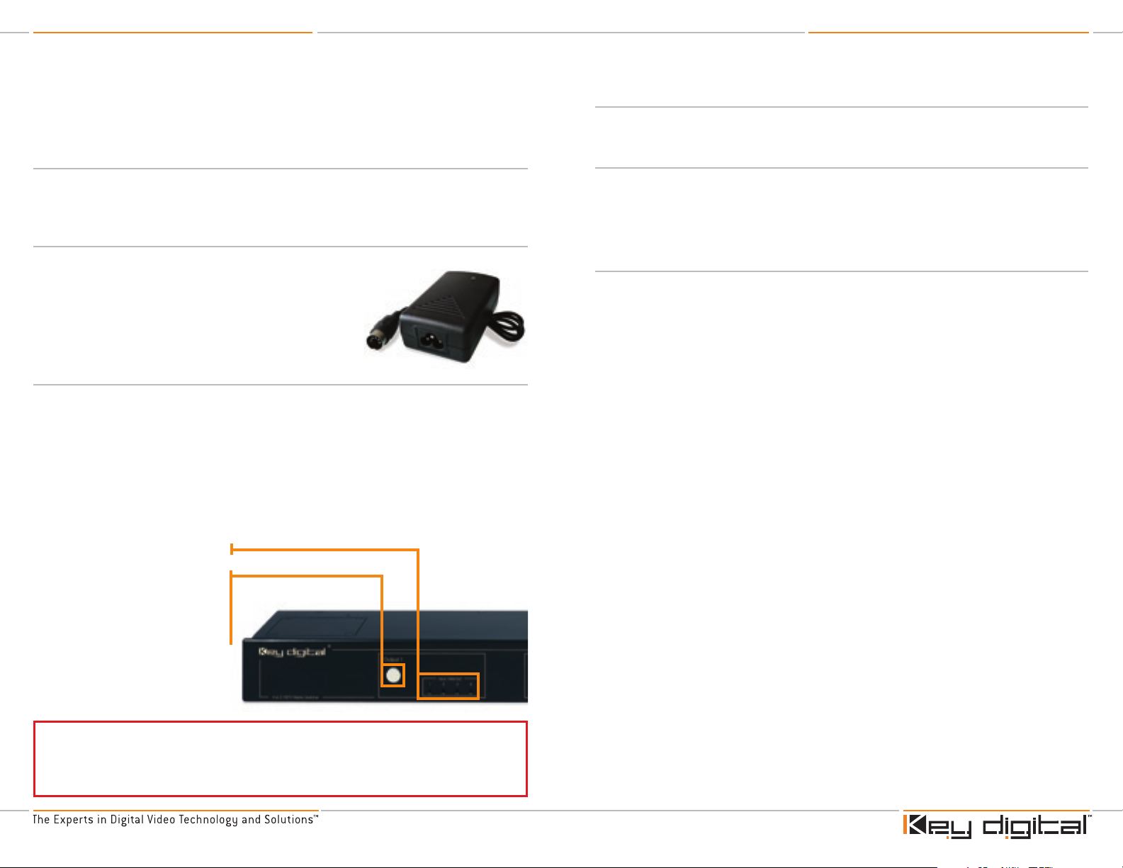
Carefully insert the Power Supply adapter plug here
IR Extender
A rear-panel IR sensor is provided, ideal to use with an IR Extender,
like one provided by Xantech. The rear panel IR sensor also supports
the IR remote control provided with the KD-MSW4x2 unit.
Mount the IR extender on the rear panel of the KD-MSW4x2 unit, or connect the wired serial connector cable to the
wired IR connector jack on the rear panel.
Wired IR
A rear-panel wired IR serial connector is provided for use with an IR Extender, like one provided by
Xantech. Connect the wired IR Extender to the 3.5 mm jack on the rear panel of the KD-MSW4x2
unit.
Applying Power
CAUTION: No other power supply adapter can be used
with the KD-MSW4x2 unit. Use only the Power Supply
provided in the carton! Using a power supply other than
the one provided by Key Digital“ with the unit VOIDS THE
WARRANTY, may cause damage to the unit and associated
equipment, and is a potential safety hazard.
Now that the A/V input and output interfaces are completed, it is recommended to double check all
cables and connections before applying power.
Always test all connections and final operation first, before sealing cables behind
walls or completing difficult wire routings.
To test connections before routing or hiding any wires behind walls or ceilings, use a reliable source
(like a DVD player) and display that is known to be functioning properly.
Once all the connections have been verified, plug the connector of the Power Supply into the
power supply input jack on the rear panel of the KD-MSW4x2 unit.
Next, plug the external Power Supply provided with the unit into an appropriate wall outlet or source
of AC power. The external power supply is rated: + 6V DC @ 5 Amps, 110-240 VAC, 50-60 Hz. For
added safety and protection it is recommended to use a good quality surge protector.
The KD-MSW4x2 unit has no physical On/Off switch, except on
the provided IR remote control.
Page 14
KD-MSW4x2 Operating Instructions
Page 24
KD-MSW4x2 Operating Instructions
Page 25
IR Remote Sensor
Use this front-panel pushbutton to
select any of the up to four source
input devices to drive the display and
audio system wired to Output 1.
Press the button and cycle through
Input 1, 2, 3, and 4.
Repeat for Output 2 using the
appropriate Output 2 pushbutton and
LEDs for monitoring the input selection.
Input 1, 2, 3, and 4 LED indicators
Operation
Matrix Switching
With all of the video and audio sources connected to the four Input Ports, and the displays and
audio systems connected to the two Output Ports of the KD-MSW4x2 unit, the matrix switcher is
ready to operate. The routing of video and audio signals from the available inputs to either output is
easily implemented using the front panel pushbuttons, and visually verifiable via the LED indicator
arrays.
The front panel of the unit provides the user with a visual representation of the two outputs.
Each of the two output sections consists of a large pushbutton switch and an array of four LED
indicators. Each of these appropriately numbered LED indicators corresponds to one of the four
available inputs.
For either display that is connected to the output of the KD-MSW4x2 unit, the desired source input
is switched by depressing the appropriate pushbutton until the LED indicator corresponding to the
chosen input is lit. The video and audio sources connected to that input are automatically switched
to the selected output. The unit also acts as a distribution amplifier, simultaneously routing a single
input to both outputs, by simply repeating the same procedure for both outputs.
Fat Boy Expansion Control
Fat Boy expansions have multiple KD-MSW4x2 units pre-wired from the factory. Each unit in the
expansion is individually addressable.
Configuring a particular unit with the desired input and output combination requires the following
successive steps:
Addressing desired Unit:
1.
Depress button 1 through 8 to select the desired unit
Addressing desired Output:
2.
Depress button ‘output 1’ (to select Output 1), or ‘output 2’ (to select Output 2)
Addressing desired Input:
3.
Depress numerical digits 1 to 4
Additional Product Features
Fade-to-Black
›
The Fade-to-Black feature allows for switching between input/output combinations without the
usual visual signal noise, glitches, and sync roll that traditionally accompany switching between
video signals. The feature momentarily forces the video image to black as the desired source
input is selected for the chosen output. This feature is applied automatically and the fade time
interval is programmable via RS-232 [see the RS-232 Command List].
Video Mute
›
Video Mute enables the user to mute the video signal (the display goes to black) at the chosen
output. Activated via IR remote control or RS-232 [see the IR remote control section of this
manual, and the RS-232 Command List for explicit instructions].
Distribution Amplifier
›
It is also possible under RS-232 control to allow any one of the four inputs to be switched and
distributed to both outputs.
Summary: Control and Monitoring
Select one of four input sources for each of the two outputs
›
Front-panel LEDs indicate the selected input, for each output
➔
Control via:
›
Front panel pushbuttons
➔
IR remote control
➔
Control all the features of the unit using the remote control
»
Power the KD-MSW4x2 On and Off
»
Requires a clear line-of-site between the IR remote control unit
»
and the front-panel IR sensor
IR Extender
➔
Wired IR
➔
All control systems (with RS-232)
➔
Power On/Off
›
Turn the KD-MSW4x2 On and Off. In the power-off mode, all front LEDs are Off and the video
outputs are muted.
Page 15

KD-MSW4x2 Operating Instructions
Page 26
KD-MSW4x2 Operating Instructions
Page 27
IR Remote Sensor
IR Extende
r
ON
Output Select
Video & Audio Mute
& Restore Keys
OFF
Numeric
Keypad
A/V Mute &
Unmute
Command Keys
Not Used
Not Used
First press either the
“Output 1” button to
select output 1, or the
“Output 2” button to
select output 2
Then press 1, 2, 3, or 4 to
direct the respective source
input device to that output
ON
Output Select
Video & Audio Mute
& Restore Keys
OFF
Numeric
Keypad
A/V Mute &
Unmute
Command Keys
Not Used
Not Used
1. FIRST SELECT
OUTPUT 1 OR 2
2. THEN DIRECT INPUT
1, 2, 3, OR 4 TO THAT
SELECTED OUTPUT
2.
1.
IR Remote Control
All the functions of the KD-MSW4x2
can be remotely accessed using the
IR remote control supplied with the
unit. The status-monitoring LEDs on
the KD-MSW4x2 front panel will light
to indicate the selections invoked by
the IR remote control, just like when
using the front-panel pushbutton
switches.
The KD-MSW4x2 4-to-2 HDT V
Matrix Switcher can be operated
remotely using the supplied
infrared (IR) remote control.
Remote Control Pushbuttons
Carefully install the batteries in the handheld remote control unit. Periodically replace batteries in
›
the handheld unit, as the operational distance of the remote control is affected by a weakened
power source.
Power “On” the Unit
To operate the KD-MSW4x2, be sure the unit is “On” (using the power supply provided with the
unit). The IR remote control has separate “On” and “Off” pushbuttons. In the power-off mode, all
front LEDs are Off and the video outputs are muted.
Matrix Switching with the IR Remote
The handheld IR remote control provides the same control functions as with the on-board
pushbutton switches. Follow the instructions below and simply select Input 1, 2, 3, or 4 for
Output 1 and Output 2.
NOTE: Be sure to select the video format
Press ‘R1’ then ‘7’ for RGBHV video
›
Press ‘R1’ then ‘8’ for YPbPr video
›
Press two digits on the IR remote control to perform the desired input and output switching function:
First, enter the desired video/audio output (1 or 2). Simply press the button ‘Output 1’ or ‘Output 2’.
›
Then, use the Numeric Keypad to enter the desired source input (1-4).
›
For example, to connect a DVD player connected on input 3 to be viewed on the display connected
to output 2, depress the keys ‘Output 2’ then ‘3’ on the IR remote control, in that order.
Note that a blue LED channel input indicator on the front panel of the KD-MSW4x2 will blink for the
selected output. Once the desired A/V input has been selected, this indicator blinks for three (3)
seconds to confirm the selection.
›
›
›
›
The IR remote control unit is based on Infrared technology, requiring a clear line-of-site from the
handheld control to the IR sensor located on the front panel of the KD-MSW4x2 unit.
The IR Extender sensor located on the rear panel can also be used to receive the IR remote
control signal, if an IR Extender is not connected or in use.
Always point the front of the remote control directly at the IR sensor located on the KD-MSW4x2.
The IR remote control may not operate properly if there are objects placed between it and the IR
sensors located on the KD-MSW4x2 front panel.
Page 16

KD-MSW4x2 Operating Instructions
Page 28
KD-MSW4x2 Operating Instructions
Page 29
Video and Audio Mute
Video Mute enables the user to mute the video signal (the display goes to black) at the chosen
output. Activated via IR remote control [or RS-232, see the RS-232 Command List].
Activate Video & Audio Mute:
Deactivate Video & Audio Mute: R1 ‡ output (1~2) ‡ down arrow
R1 ‡ output (1~2) ‡ up arrow
KD-MSW4x2 IR Remote Control Function Table
In addition to some of the functions described above, a complete list of all of the functions and
corresponding button sequences that can be executed from the IR remote control provided with
the KD-MSW4x2 are listed below:
Button Sequence Function
“Output 1” “1” Output 1 = Input 1
“Output 1” “2” Output 1 = Input 2
“Output 1” “3” Output 1 = Input 3
“Output 1” “4” Output 1 = Input 4
“Output 2” “1” Output 2 = Input 1
“Output 2” “2” Output 2 = Input 2
“Output 2” “3” Output 2 = Input 3
“Output 2” “4” Output 2 = Input 4
“Output 1” “U1” Output 1 Audio Mute
“Output 1” “U2” Output 1 Audio Restore (unmute)
“Output 2” “U1” Output 2 Audio Mute
“Output 2” “U2” Output 2 Audio Restore (unmute)
“R1” “Output 1” “Up” Output 1 Video and Audio Mute
“R1” “Output 1” “Down” Output 1 Video and Audio Restore (unmute)
“R1” “Output 2” “Up” Output 2 Video and Audio Mute
“R1” “Output 2” “Down” Output 2 Video and Audio Restore (unmute)
“R1” “U4” “Up” All Outputs Video and Audio Mute
“R1” “U4” “Down” All Outputs Video and Audio Restore (unmute)
“R1” “7” All video outputs set to RGBHV
“R1” “8” All video outputs set to YPrPb
“R1” “9” Front buttons disabled
“R1” “0” Front buttons enabled
RS-232 Commands and Protocol
The KD-MSW4x2 4-to-2 HDTV Matrix Switcher can also be remotely controlled via its RS-232 port
by systems such as Crestron, AMX, ELAN, and Control4, utilizing industry standard commands
PROTOCOL:
4800 Baud rate
›
8 data bits
›
1 Stop bit
›
No parity
›
RS-232 Cable
Carefully insert an RS-232 cable (9-pin) to the back of the unit, and to an appropriate PC
or Control System.
An RS-232 cable is not supplied with the KD-MSW4x2 unit.
The RS-232 Command List for the KD-MSW4x2 HDTV Switcher is as follows:
I/O switching command:
1.
CCxy
x = output position (1...2), y = input position (1...4)
Status command:
2.
CCww
Both commands give the following response:
a) UUy1y2y
b) Y1y2y3y4 – input states (1...4)
Address command:
3.
CCA<number (1~9)>
Note: Since both commands are of a defined length, no terminator is required
CCA9 : Selects default KD-MSW4x2 unit (non addressable)
CCA1~8 : Selects the KD-MSW4x2 unit corresponding to that predetermined
numerical address
Example:
CCA5 sets the address to “5”
The user must then press “5” to select/change a different source input on that unit
IR 5
‡‘output 1’ ‡3 links output 1 to input 3
Page 17

KD-MSW4x2 Operating Instructions
Page 30
KD-MSW4x2 Operating Instructions
Page 31
Video Mute command:
4.
IR : R1
R1
‡ output 1-2 ‡ Up arrow : Enable Mute
‡ output 1-2 ‡ Down arrow : Disable Mute
Example:
R1
Fade to Black interval set up command:
5.
Period that will be muted is twice the interval
CCi<number(0~9)>
CCI0 : No mute
CCI1 : 28 ms mute
CCI2 : 40 ms mute
CCI3 : 80 ms mute
CCI4 : 120 ms mute
CCI5 : 160 ms mute
CCI6 : 240 ms mute
CCI7 : 320 ms mute
CCI8 : 400 ms mute
‡ output 1 ‡ Up arrow : output 1 is muted
Note: R1‡ U4 ‡ Up arrow mutes every output
RS-232: CCm<number(1~3)> : Enable mute
CCn<number(1~3)> : Disable mute
CCI9 : 600 ms mute
Power On/Off
6.
s : Power OFF the KD-MSW4x2 unit
q : Power ON the KD-MSW4x2 unit
Output set up command:
7.
IR: R1
R1
RS-232 : CCOR : RGBHV mode
‡ 7 : RGBHV mode
‡ 8 : Component mode
CCOC : Component mode (factory default)
Factory default command:
8.
CCF0 : Resets memory
Inputs for every output = 1
Mute Interval = 240 ms
IR Remote Control commands:
9.
I :Disable IR Remote Control
u :Enable IR Remote Control
Front Panel Pushbutton commands:
10.
d : Disable front panel pushbutton controls
e : Enable front panel pushbutton controls
Switching any input to both outputs commands (Distribution Amplifier mode):
11.
z<number(1~4)> : Switches both outputs to any one input temporarily; can be restored
to original selection
z0 : Restores the original input-output configuration
Example:
z3 : Switches both outputs to input 3
TECHNICAL SPECIFICATIONS
Model #: KD-MSW4x2
4 Inputs to 2 Outputs HDTV Matrix Switcher
The Fat Boy Series KD-MSW4x2 by Key Digital™‚ is an analog HDTV 4-Input to 2-Output matrix
switcher and distribution amplifier.
Matrix Switching
Supports Video and Audio
›
Four (4) Input Ports and two (2) Output Ports provided
›
Matrix switch one of up to four inputs to either of two outputs
›
For each of the two outputs that can be used to drive separate displays, one of the four
➔
source inputs can be independently selected
Also acts as a distribution amplifier, simultaneously routing any individual input to both outputs
›
Using RS-232 control
➔
Expandable
›
Professional Switching Features
Fade-to-Black: allows for switching between input/output combinations without the usual
›
visual signal noise, glitches, and sync roll that traditionally accompany switching between video
signals
The feature momentarily forces the video image to black as the desired source input is
➔
selected for the chosen output
This feature is applied automatically
➔
Fade time inter val is programmable via the RS-232, and is equivalent to a “Video Mute” to
➔
force the video to black during switching
See the RS-232 Command List
»
Video Mute: enables the user to mute the video signal (the display goes to black) at the chosen
›
output
Input/Output Ports and Formats
The output format = the format of the selected input source
›
Each Input and Output Port is comprised of six (6) color-coded RCA jacks:
›
3 analog video connectors
➔
2 analog audio connectors
➔
The analog audio input/output connectors also serve as the horizontal and vertical sync
»
for RGBHV signals
1 PCM digital coax audio connector
›
Page 18

KD-MSW4x2 Operating Instructions
Page 32
KD-MSW4x2 Operating Instructions
Page 33
Each Port supports:
›
YPbPr component video, analog stereo left and right audio, and digital PCM audio
➔
RGBHV video and digital PCM audio
➔
RGB video with sync on the green channel, analog stereo left and right audio, and digital PCM
➔
audio
S-Video and composite video (CVBS), with adapters
➔
Each connector can accommodate various signals, on a shared basis:
›
Red Connector: Pr/R
➔
Pr label is for component video
»
R label is for the red channel for RGBHV video
»
Green Connector: Y/G
➔
Y label is for component video
»
G label is for the green channel for RGBHV video
»
Blue Connector: Pb/B
➔
Pb label is for component video
»
B label is for the blue channel for RGBHV video
»
White Connector: L/H
➔
L label is for the left analog stereo audio channel
»
H label is for the horizontal sync for RGBHV video
»
Red Connector: R/V (Right analog stereo audio, or vertical sync for RGBHV video)
➔
R label is for the right analog stereo audio channel
»
V label is for the vertical sync for RGBHV video
»
Black Connector: PCM
➔
For PCM digital coax audio
»
Resolution
The output resolution = the resolution of the selected input source
›
Handles all HD and SD resolutions (50 and 60 Hz) including 1080p/60
›
Supports analog video bandwidths up to 300 MHz
›
Performs no video or audio processing:
›
Introduces no degradation in video or audio signal quality
➔
Compatible Video Signals
Compatible with all standard analog video signal formats that use 50 Hz or 60 Hz refresh rates,
›
including:
1080p, 1080i, 720p, 576p, 576i, 540p, 480p, 480i
➔
Video Characteristics
Output stage drives high-quality, equal-length video cables up to 300’ or more
›
1V p-p @ 75 ohms, terminated
›
Composite video sync on “Y” input (YPbPr)
›
Video bandwidth:
›
-3 dB @ 300 MHz
➔
Linear phase pass-band
➔
Unity video gain
›
Input terminations: for proper operation of the high quality electrical circuits in the KD-MSW4x2
›
unit, do NOT “daisy chain” inputs:
Each input of the KD-MSW4x2 has its own 75 ohm termination
➔
Do NOT feed a source to multiple KD-MSW4x2 inputs without proper distribution equipment
➔
Analog Audio Characteristics
Left and Right stereo on two color-coded RCA connectors
›
High-impedance (1K ohm) line level inputs
›
Analog Audio Muting provided
›
Analog Audio is not supported for RGBHV video applications:
›
Connectors are used for H&V
➔
Digital Audio Characteristics
Standard digital PCM coax format on one color-coded RCA connector
›
Control and Monitoring
Select one of four input sources for each of the two outputs
›
Front-panel LEDs indicate the selected input, for each output
➔
Control via:
›
Front panel pushbuttons
➔
IR remote control, with extensive commands and control
➔
IR Extender
➔
Wired IR
➔
All control systems (with RS-232, cable not supplied)
➔
Connectors
Each Input and Output Port is comprised of six (6) color-coded RCA jacks
➔
RS-232C: D-sub 9-pin
➔
5-pin power connector for external AC-DC power supply input
➔
3.5 mm jack for serial, wired IR input
➔
Page 19

KD-MSW4x2 Operating Instructions
Page 34
KD-MSW4x2 Operating Instructions
Page 35
Mechanical
Size: 16” (L) x 4” (W) x 1.7” (H)
›
Weight: 5 lbs.
›
Enclosure Type: Metal
›
Rack Mount Size: 1 U
›
Power Requirements
External power supply provided
›
+ 6V DC @ 5 Amps, 110-240 VAC, 50-60 Hz
›
CAUTION: No other power supply adapter can be used
with the KD-MSW4x2 unit. Use only the Power Supply
provided in the carton! Using a power supply other than
the one provided by Key Digital™ with the unit VOIDS THE
WARRANTY, may cause damage to the unit and associated
equipment, and is a potential safety hazard.
How to Contact Key Digital
™
Repairs and Warranty Service
Should your KD-MSW4x2 4-to-2 HDTV Matrix Switcher require warranty service, please contact
›
Key Digital™ to obtain a Returned Materials Authorization (RMA) number
Please contact us at either:
›
➔
Phone:
➔
E-mail:
1-914-667-9700 ext 215
rma@keydigital.com
Technical Support
For technical questions about using our products, please contact us at either:
›
➔
Phone:
➔
E-mail:
1-914-667-9700 ext 301
tech@keydigital.com
Customer Support
For customer support questions about using our products, please contact us at either:
›
➔
Phone:
➔
E-mail:
1-914-667-9700 ext 223
customersupport@keydigital.com
Warranty
All Key Digital™ products are built to high manufacturing standards and should provide years of
trouble-free operation. They are backed by a limited two-year parts and labor warranty.
Page 20

KD-MSW4x2 Operating Instructions
Page 36
KD-MSW4x2 Operating Instructions
Page 37
Installation Notes Installation Notes
 Loading...