

Page 1
4 Inputs to 2 Outputs POH/HDBaseT/HDMI/VGA
Multi-View Seamless Presentation Matrix Switcher.
Includes 1 Power over HDBaseT/HDMI Rx Extender.
Screen Modes
KD-MLV4x2Pro
Operating Instructions
The Experts in Digital Video Technology and Solutions
™
Page 2

4
Always follow the instructions provided in this Operating Manual.
Table of Contents
Quick Setup Guide .......................................................... 2
Application Examples ........................................................ 3
Connections, Buttons and LEDs ................................................ 4
Front Panel Operation ........................................................ 8
IR Remote Control.......................................................... 10
Web Control Interface ....................................................... 12
Custom Layout Examples .................................................... 17
RS-232 and TCP-IP Commands and Protocol..................................... 20
Window Transparency and Border Settings ....................................... 23
Specifications ............................................................. 24
Important Product Warnings & Safety Instructions: ................................. 25
How to Contact Key Digital
®
.................................................. 26
Warranty Information ........................................................ 26
Introduction
Key Digital’s KD-MLV4x2Pro is a seamless multi-format video matrix with UHD/4K resolution
up-scaling, multi-view window processing, audio de-embedding, independent audio from
video matrix selection, and HDCP 2.2 compliancy. The HDMI and HDBaseT output are
independent in full-screen and quad screen modes. KD-X222PO Rx HDBaseT extender
receiver is included and powered from the matrix.
KD-MLV4x2Pro is designed to fit a wide variety of professional video installation and live-
event needs. It is ideal for digital signage, video wall, conference & board room, huddle
spaces, home theater, and bar/restaurant applications.
Page 3

1
Key Features
› Multi-View Window Processing:
Create & store custom multi-view layouts, recall custom
presets in 1080p (2K) Multi-view mode
»
Quadrant Mode (4K or 2K):
Independent outputs in four equally-sized windows
»
Multi-view Mode (2K):
Linked/mirrored outputs in customized screen layout
› Seamless Switching:
Uninterrupted screen transitions during source selections
› Independent Matrix Switching:
In full-screen and quadrant modes, linked/mirrored in
multi-view mode
› Image Layering:
Stack images with customizable priority settings
› Window Transparency and Border:
View content through each other and choose window
bezel width and coloring
› Multi-format Switch:
»
Input:
2 HDMI, 2 HDMI or Analog video, all with external audio
»
Output:
1 HDMI and 1 HDBaseT output. Rx unit included.
› HDBaseT Built-In:
Included KD-X222PORx unit is powered by at KD-MLV4x2Pro
› Signal Extension:
» Up to 200 feet @ 1080p/60, 1080p/24, 1080i, 720p with third-party CAT5e/6
» Up to 125 feet @ 4096x2160 30Hz [4:4:4] 8bit with third-party CAT5e/6
› Ultra HD/4K Up-scaling:
Outputs independently upscale to 4096x2160 30Hz [4:4:4] 8bit in
4K Quadrant mode
› HDCP 2.2 Licensing:
Fully licensed and compatible with HDCP 2.2
› Resolution Support:
Supports SD, HD, and VESA input resolutions up to 1080p /
1920x1200 on HDMI and analog video Inputs. Outputs fixed to 1080p or 4K.
› Audio De-Embedding:
Audio from the selected input can be de-embedded through the Coax
digital (PCM) output in addition to the HDMI output
› Dolby Digital & DTS Audio:
Supports 2-channel and multi-channel audio
formats up to 5.1 Dolby
®
/ DTS™ lossless compressed digital surround sound
› Independent Video & Audio: Listen to any audio source while in quadrant or multi-view modes
› Deep Color Support:
Up to 12 bits/color
› Analog to Digital Video Conversion:
Analog video input ports support VGA / DB15 or
Component / YPbPr signal types
› Full Buffer System
™
:
Manages TMDS re-clocking / signal re-generation, HDCP authentication
to source & display, and EDID Control handshake
› EDID:
Internal library with 5 default EDID configurations for input, in addition to native EDID
data for any Output / Display
› TMDS Re-clocking: Support for long HDMI connectivity using Key Digital
®
HDMI cables
› Control:
Front panel buttons, IR, RS-232, TCP/IP and Web Control
› Web Control Interface:
Reduces installation time and provides basic and advanced video
and audio setup
› Control System Support:
Compatible with Compass Control®, AMX®, Control4®, Crestron®,
KNX
®
, RTI®, Savant, URC®, Honeywell®, HAI®, Leviton®, etc.
› Key Digital
®
App Ready:
Can be controlled over TCP/IP via Key Digital® App
Accessories
› Power Supply: KDPS60W12VQ, 12V/5A, screw-in type
› IR Remote Control: KD-RMMLV
› Rack ears / Operating Instructions / Warranty Card
Page 4
2
Quick Setup Guide
1. Begin with the main unit, Rx unit, and all input/output devices turned off and
power cables removed
2. Connect Video and Audio Sources to the desired KD-MLV4x2Pro input ports
3. Connect HDMI output ports to a display/sync device using Key Digital HDMI cables and audio
devices to the audio outputs
4. Connect the Rx unit’s HDMI output a display/sync device, and use a CAT5e/6 cable to
interconnect the Rx and KD-MLV4x2Pro’s HDBaseT ports.
5. Connect power to the KD-MLX4x2Pro and power on, then repeat for source devices,
then display devices.
6. Choose desired screen layout via front panel buttons, IR, web control interface, RS-232 or TCP/IP
» a. Some features not available in all layout and control types. Please refer to following
sections for more information on controllability and setup for each control type.
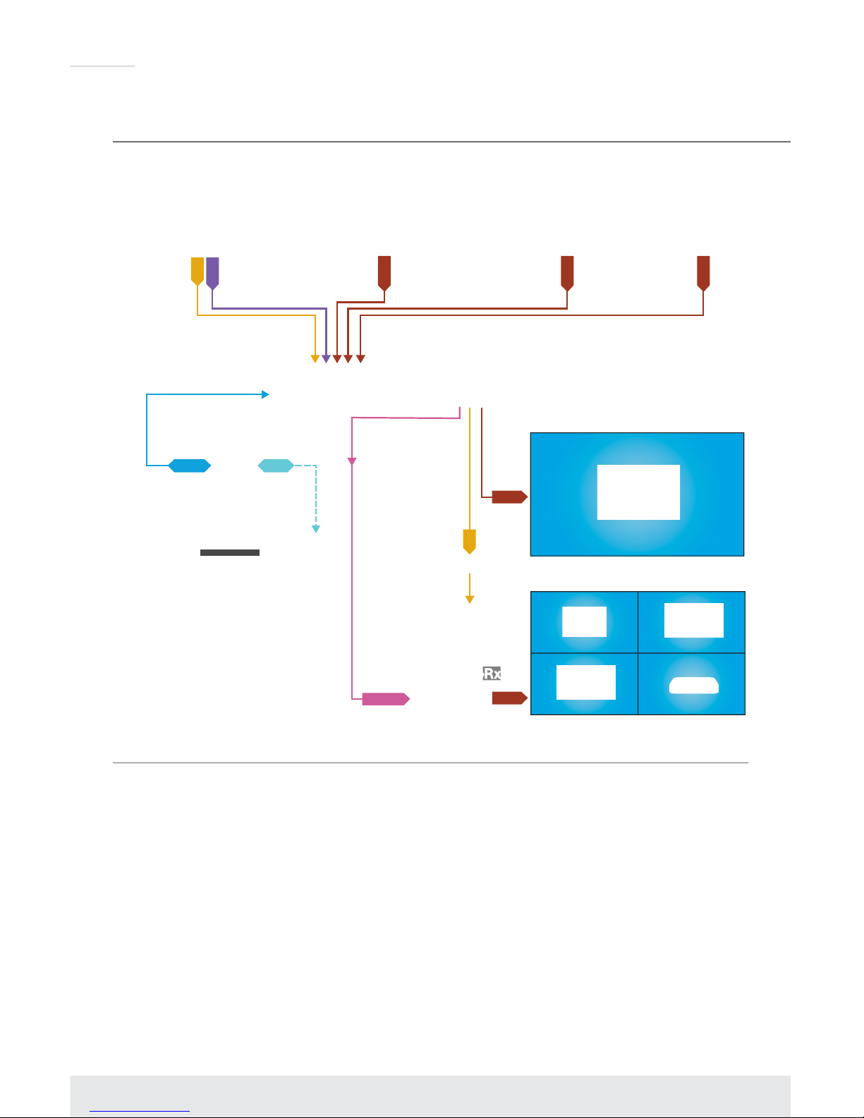
Application Examples
Display 1: Fullscreen Mode
Display 2: Quadrant Mode
Signage PC 1
Mac Mini
Digital Signage
VGA Laptop
VGA
L/R
HDMI
HDMI
HDMI
Signage PC 2
HDMI
HDMI
L/R
HDMI
Network
Router
Master Controller
RJ45 WiFi
RS-232
Network
Router
RJ45 WiFi
Satellite/Cable
Game 1
KD-ProCL1
Key Digital
®
App
KD-MLV4x2Pro
KD-MC1000
KD-X222PO
KD-AMP220
2 Ch Amplifier
CAT5e/6
KD-MLV4x2Pro
Digital Signage
Page 5
3
IR Emitter Control
When using an IR Emitter / IR Extender (sold separately), the IR Emitter must be mounted over
the IR Sensor on the front of the KD-MLV4x2Pro. One end of the cable is connected to the IR
Receiver/ Master Controller / IR Extender / IR Connecting Block, while the other end is mounted
over the IR Sensor of the KD-MLV4x2Pro.
Serial IR Control
As a more robust alternative to optical IR, KD-MLV4x2Pro may also be controlled via hard-wired
IR. Use a 3.5mm Male Mono plug with the IR Signal carried on the tip of the connector.
Rack Mounting
Secure the rack ears to each side of the KD-MLV4x2Pro with the supplied hardware then fasten
the unit to the rack rails with the included machine screws.
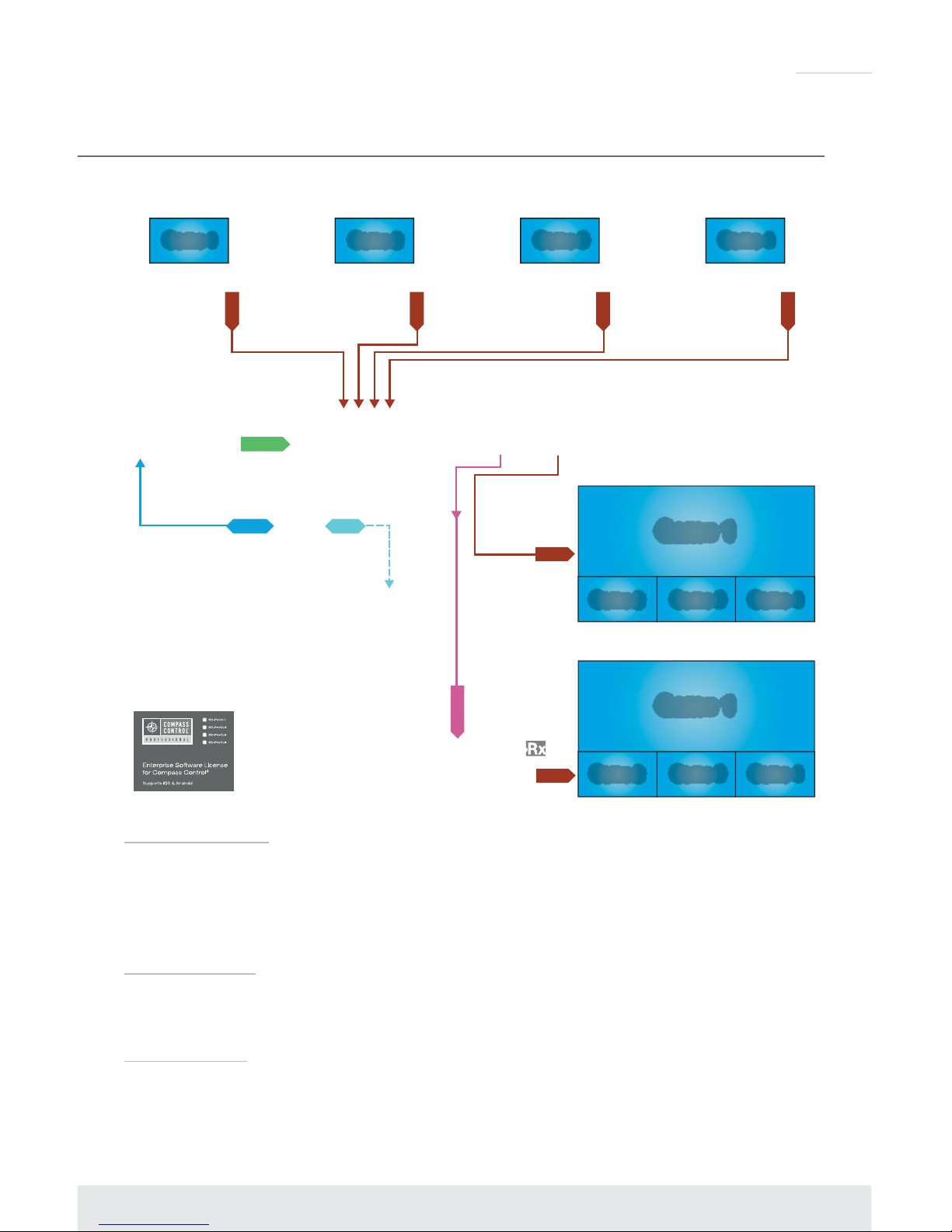
Display 1: MultiView Mode
Display 2: MultiView Mode
HDMI
HDMI
HDMI
HDMI
HDMI
Master Controller
RS-232
Network
Router
RJ45 WiFi
Satellite/Cable
Game 1
Satellite/Cable
Game 2
Satellite/Cable
Game 3
Satellite/Cable
Game 4
Game 1
Game 2 Game 3 Game 4
Game 1
Game 2 Game 3 Game 4
KD-ProCL1
KD-MLV4x2Pro
KD-MC1000
HDMI
KD-X222PO
CAT5e/6
Bar/Restaurant
Page 6
4
Connections, Buttons and LEDs
Rear Panel Connections:
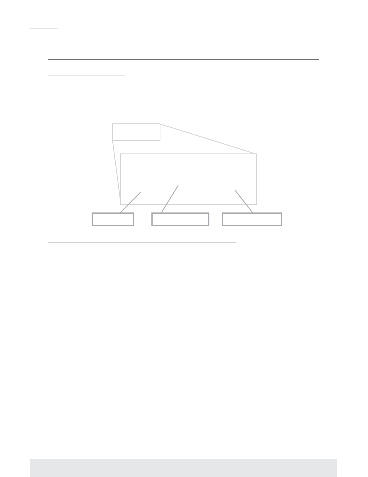
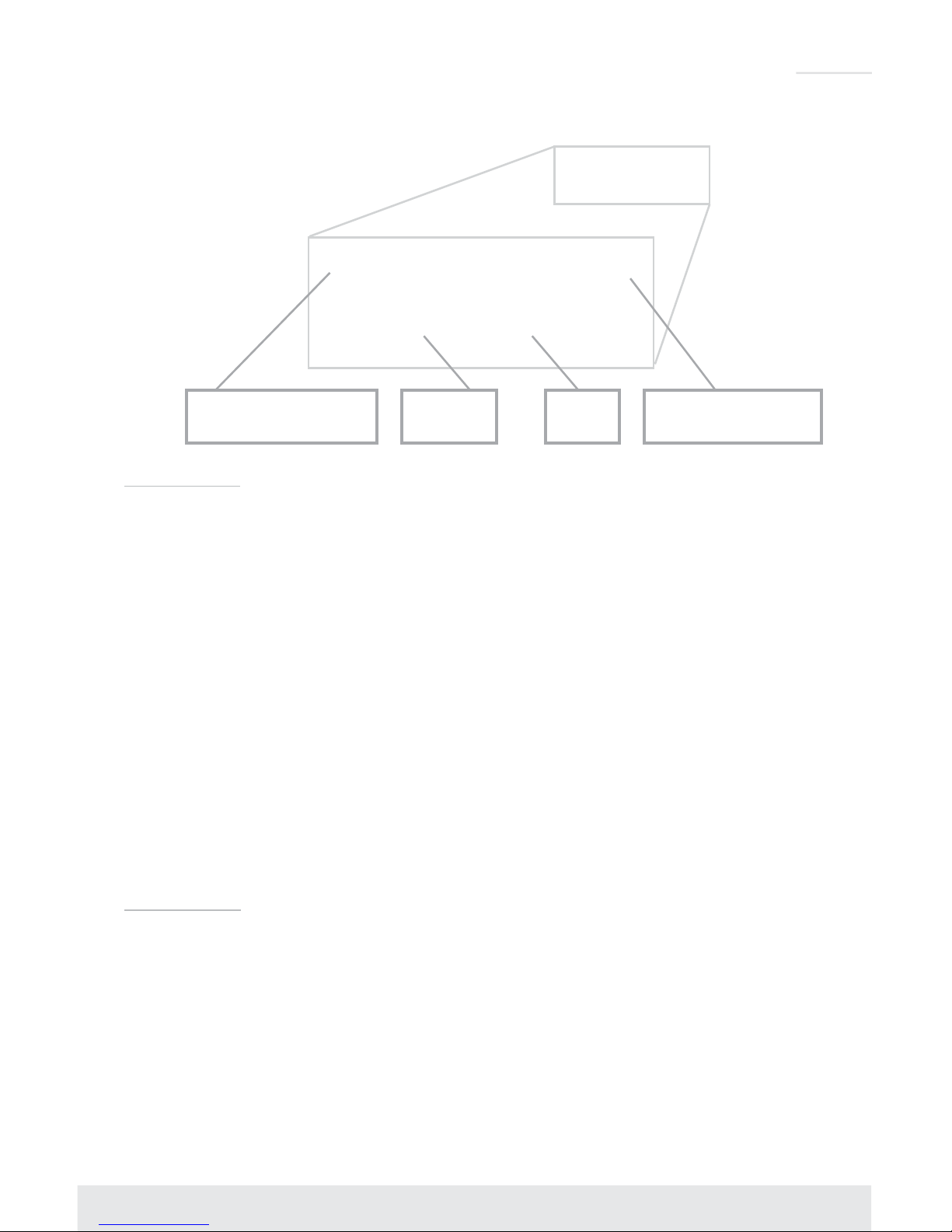
All connections to the KD-MLV4x2Pro are found on the rear panel of the unit. Refer to the
illustrations below for port assignments while making connections:
HDMI Input Analog L/R Input VGA / DB15 Input
Input Connections are located on the left side of the back panel
› HDMI Inputs (4 total)
» Compliant with HDCP 2.2
» Maximum input resolution = 1080p@60fps
» Does not support CEC
» Supports 2ch and surround audio formats up to Dolby/DTS 5.1ch
» Active link (voltage + data) status with connected source can be viewed with RS-232 or
TCP/IP terminal
› VGA / DB15 Inputs (4 total)
» Supports either VGA or Component video signals
» Component Video input type must be specified via RS-232 or TCP-IP command, if desired
» Default analog video input type is VGA
» VGA / DB15 supported input resolutions: 640x480@60/75, 800x600@56/60/75,
1024x768@60/75, 1280x768@60/75, 1366x768@60/75, 1280x1024@60/75,
1440x900@60/75, 1600x900@60, 1600x1200@60, 1920x1080@60, 1920x1200@60
» Component / YPbPr supported input resolutions: 480i@30, 576i@25, 480p@60, 576@50,
720p@50/60, 1080i@25/30, 1080p@50/60
› Analog L/R Inputs (4 total)
» 3.5mm stereo connector
» Sampling frequency = 48KHz, 24Bits
Page 7
5
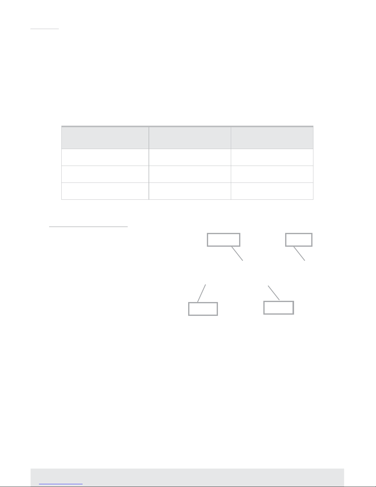
HDMI
Output
HDBaseT
Output
Coaxial PCM Digital
Audio Output
Analog L/R Balanced/
Unbalanced Output
Video Outputs
› HDMI Output (1 total)
» Supports either 1080p@60 fps or 4096x2160 30Hz [4:4:4] 8bit
» 4096x2160 resolution supported in 4K Quadrant mode only
» Does not support CEC, 3D, ARC, Ethernet over HDMI
» Active link (voltage + data) with connected output device can be viewed with RS-232 or
TCP/IP terminal
› HDBaseT Output/Tx (1 total)
» Native integration with KD-X222PO Rx (included)
» Provides power to KD-X222PO Rx via HDBaseT
» Sends HDMI video & audio of selected source, as well as IR or RS-232 connected into IR/
RS-232 pass-through port to KD-X222PO Rx
» Integrates with third-party HDBaseT Rx built-in on compliant devices such as monitors and
projectors.
» Compatibility is not guaranteed with third-party devices
» Active link (voltage + data) with connected output device can be viewed with RS-232 or
TCP/IP terminal
Audio Outputs
› Analog L/R Balanced/Unbalanced (1 per output)
» 6-Pin Terminal Block
» Pin assignment:
» Pin 1 = Left +
» Pin 2 = Left ground
» Pin 3 = Left –
» Pin 4 = Right +
» Pin 5 = Right ground
» Pin 6 = Right –
Page 8
6
› Coaxial PCM Digital (1 per output)
» RCA connector, SPDIF format
› Audio outputs provide de-embedded audio output from selected HDMI input source
› There are no volume or tone control features, only muting control of the external audio outputs via
RS-232 and TCP/IP
› There are no format conversion features. Audio must be configured in the source.
For example, in order to achieve 2ch analog audio output, the selected HDMI input source audio
format must be 2ch.
Audio Input
Signal Format
Audio L/R
Output
Digital Audio
Output
2CH PCM Pass-through Pass-through
Multi-Channel PCM MUTE MUTE
DOLBY/DTS MUTE Pass-through
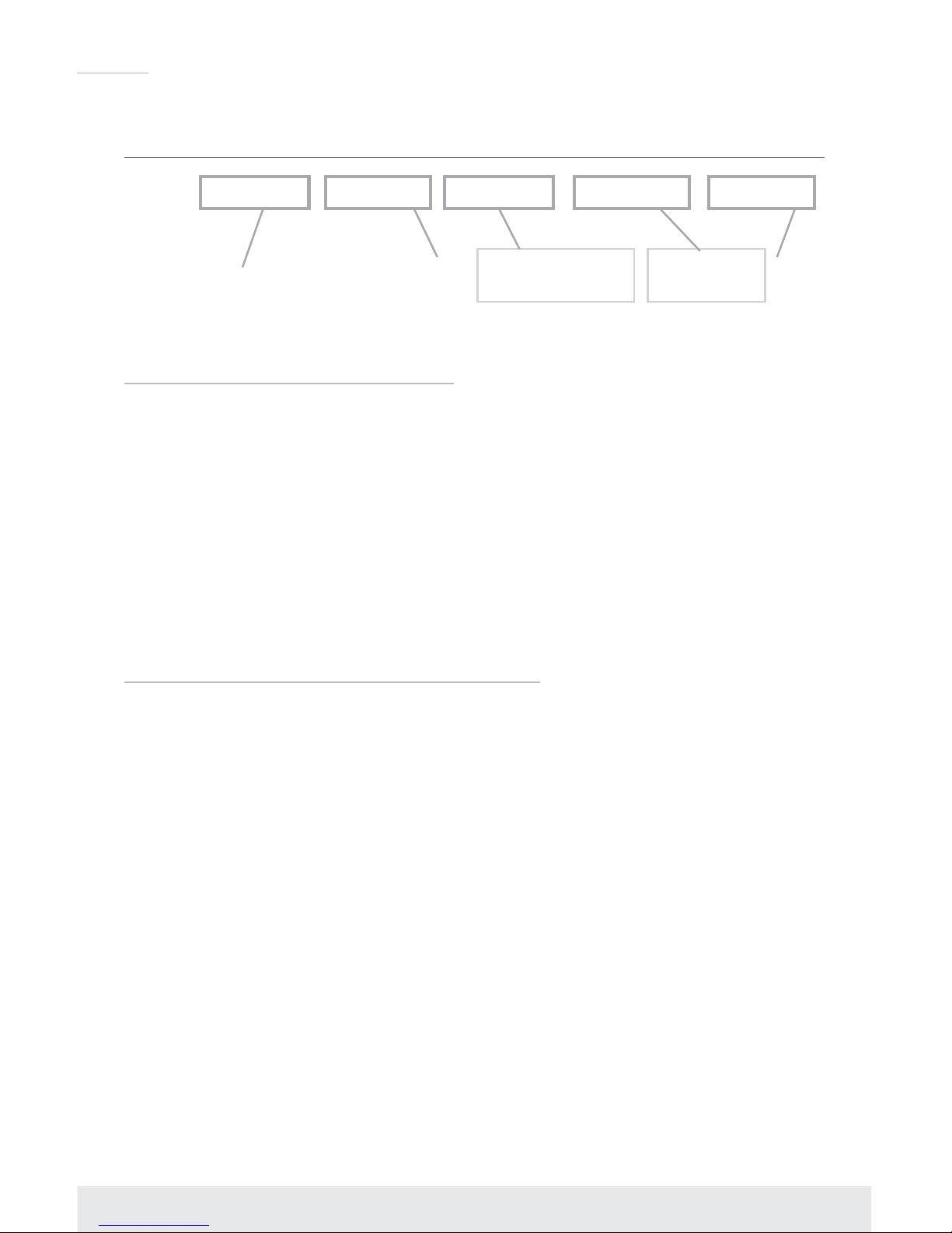
Control and Power Ports
PowerSerial IR
RS-232
TCP/IP
› KD-MLV4x2Pro Control Ports
» Serial IR and RS-232 on a 6-Pin Terminal Block
» Advanced control possible via RS-232 and TCP/IP. Basic control via IR
» Pin out of Serial IR / RS-232 Main Unit Control
» Pin 1 = IR In
» Pin 2 = IR Ground
» Pin 3 = N/C
» Pin 4 = RS-232 Tx
» Pin 5 = RS-232 Ground
» Pin 6 = RS-232 Rx
» For TCP/IP control, connect an Ethernet cable from a network router or directly from a PC
» The TCP/IP port is used for control and firmware updates
» Refer to the RS-232 and TCP/IP Commands and Protocol section for complete code-
set
Page 9

7
» A Network Setup Tutorial video is available at: https://youtu.be/AMC7KvPPJsg
» The default TCP-IP address of the KD-MLV4x2Pro unit is
192.168.1.239
» The default port number is
23
.
IR/RS232 Switch
HDBaseT IR/RS-232
pass-through port
› HDBaseT IR/RS-232 pass-through port
» Supports bi-directional control with KD-X222PO Rx
» Choose IR or RS-232 via slide Switch
» Pin out (KD-MLV4x2Pro):
» Pin 1 = RS-232 Tx / IR Out
» Pin 2 = Ground
» Pin 3 = RS-232 Rx / IR In
» Pin out (Rx unit):
» Pin 1 = IR In
» Pin 2 = IR Ground
» Pin 3 = 5V (IR sensor power)
» Pin 4 = RS-232 Tx / IR Out
» Pin 5 = Ground
» Pin 6 = RS-232 Rx
› IR Accessory Wiring
» IR Emitter:
» IR Signal = Dashed
» Ground = Solid
» IR Sensor:
» a. IR Signal = White
» b. Ground = Black
» c. Sensor Power = Red
Page 10
8
Front Panel Operation
Mode Select Input SwapLCD Screen HDMI/VGA Input Select
The front-panel of KD-MLV4x2Pro features 3 sets of buttons:
HDMI / VGA input-type select (2 buttons)
› Enables selection of the HDMI digital video input or VGA analog video input for the specified
source
» Note: Selection of VGA or Component video input type for the Analog Video input must be
done by RS-232 or TCP-IP
› To select HDMI or VGA input type:
» 1. Press either HDMI or VGA, as desired
» 2. Using the Output 1 row of buttons, press the desired input number that you’d like to
apply the setting to
» 3. Confirmation of your selection is shown on the LCD screen
» a. Example: When input 1 input-type has been set to VGA, the LCD screen will show
[A/V SOURCE ] INPUT 1 = VGA
Matrix switching source select (2 rows of 6 buttons)
› Enables selection of any input source (1-4) for the respective output, or to enter 4K Quadrant or
2K Quadrant modes
» 2K QV mode divides the image into 4 equally-sized quadrants
» 4K QV mode divides the image into 4 equally-sized quadrants
» The overall image is 4K, making each quadrant a full-1080p resolution
› The selected source is indicated by a blue fill of the respective button
› If any 4K or 2K QV quadrant modes are chosen, the Matrix switching source select buttons will
not be illuminated for the respective output
› Confirmation of your matrix switching selection and respective input-type for selected source is
shown (in parenthesis) on the LCD screen:
» OUT 1: IN 1 (HDMI)
» OUT 2: IN 2 (VGA)
› Confirmation of 4K quadrant mode and respective input-type for sources (in parenthesis) is shown
on the LCD screen:
» OUT 1: 4K QV (HVHH)
» OUT 2: IN 2 (VGA)
Page 11

9
1080p(2K) Multi-View mode select (5 buttons) and Input Swap (1 button)
› Pressing any of the 5 Multi-View mode select buttons will activate both outputs to
simultaneously enter the selected screen layout
»
IMPORTANT:
Selecting 2K Multi-View mode results in linking of the two KD-MLV4x2Pro
outputs (showing same image at the same time).
› The 5 layouts are, by default:
»
1. Quadrant
»
2. Top
»
3. Bottom
»
4. Left
»
5. Right
› If desired, the layouts can be over-written via the Web Control Interface, RS-232, or TCP-IP, by
saving to the KD-MLV4x2Pro’s preset bank
› Resetting the KD-MLV4x2Pro to factory default will restore these 5 layouts in the preset bank as
layouts 1-5, respectively.
› The
Input Swap
button serves 2 purposes:
» 1. If used in standard 4x2 matrix, full-screen mode, pressing Input Swap will simultaneously
and synchronously switch both outputs:
» 2. If used in Multi-View mode, pressing Input Swap rotates source content of the 4 inputs
through the 4 windows:
› Confirmation of 2K multi-view mode and respective input-type for sources (in parenthesis) is
shown on the LCD screen:
» OUT 1: 2K MV (VHHH)
» OUT 2: 2K MV (VHHH)
Factory Default Reset via the Front panel
To reset the unit to Factory Default settings, simultaneously press and hold the HDMI Input-Type
Select button and Input Swap button for approximately 10 seconds
› Default Settings:
» Unit Address is 00
» Output 1 is set to Input 1
» Output 2 is set to Input 1
» EDID to all inputs is Default 2 (1080p, 2ch audio)
» All other internal parameters set to default
Page 12
10
IR Remote Control
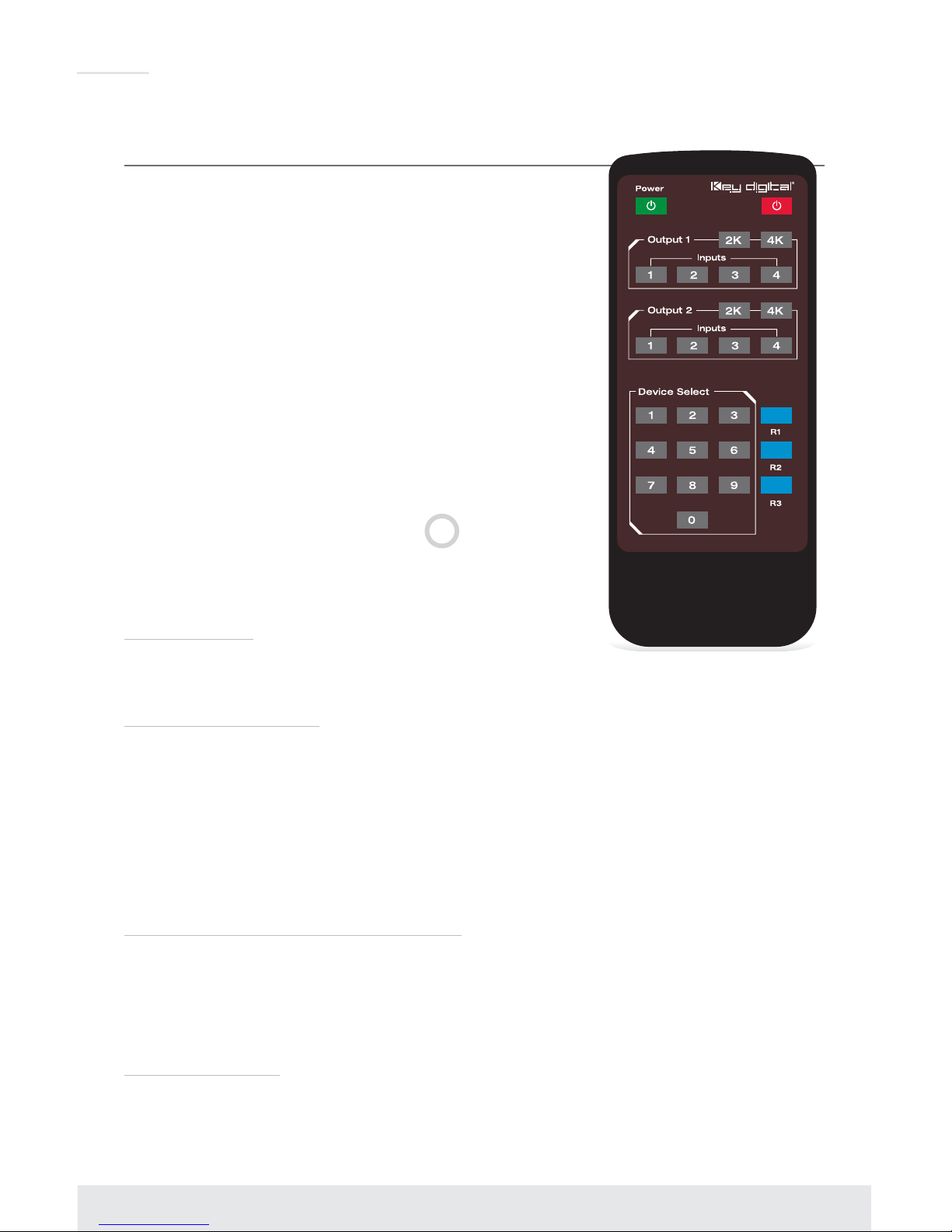
The IR Remote Control included with KD-MLV4x2Pro provides
convenient but limited control of the switching features and unit setup.
There are 3 main groups of controls:
› Group for output 1 source and 2K / 4K output resolution select
› Group for output 2 source and 2K / 4K output resolution select
› Group for device select buttons
› Additionally, there are discrete power on and off buttons and
function buttons R1, R2, and R3.
» The remote is powered by a CR2025 type battery
» The circular IR sensor accepts control signals from the
remote control. The sensor is located in the center of the
front panel.
Switching via IR
To execute a switching command, press the desired source select
button within the desired output button group.
Multi-View Modes via IR
1080p (2K) Multi-View presets can be called using the IR remote by pressing the following remote
button sequence:
› R1, 0-9
»
1-9
= Desired preset, where 1-5 are, be default, Quadrant, Top, Bottom, Left, Right.
» All presets may be overwritten using the Web Control Interface, RS-232,
or TCP-IP terminal
»
0
= Input Swap
Quad-View/Multi-View Audio Select via IR
You may select the desired audio source if in Quad or Multi-View modes with the following twobutton remote sequence:
› R3, A
»
A
= Input Select button from Output 1 or Output 2 button group
EDID Control via IR
KD-MLV4x2Pro has a built-in library of 5 EDID settings and the ability to copy EDID data from any
output specified via IR, RS-232, and TCP-IP. EDID Control setup via RS-232 and TCP-IP can be
found in the RS-232 Commands and Protocol TCP-IP Setup and Control sections.
Page 13
11
Set to Default EDID
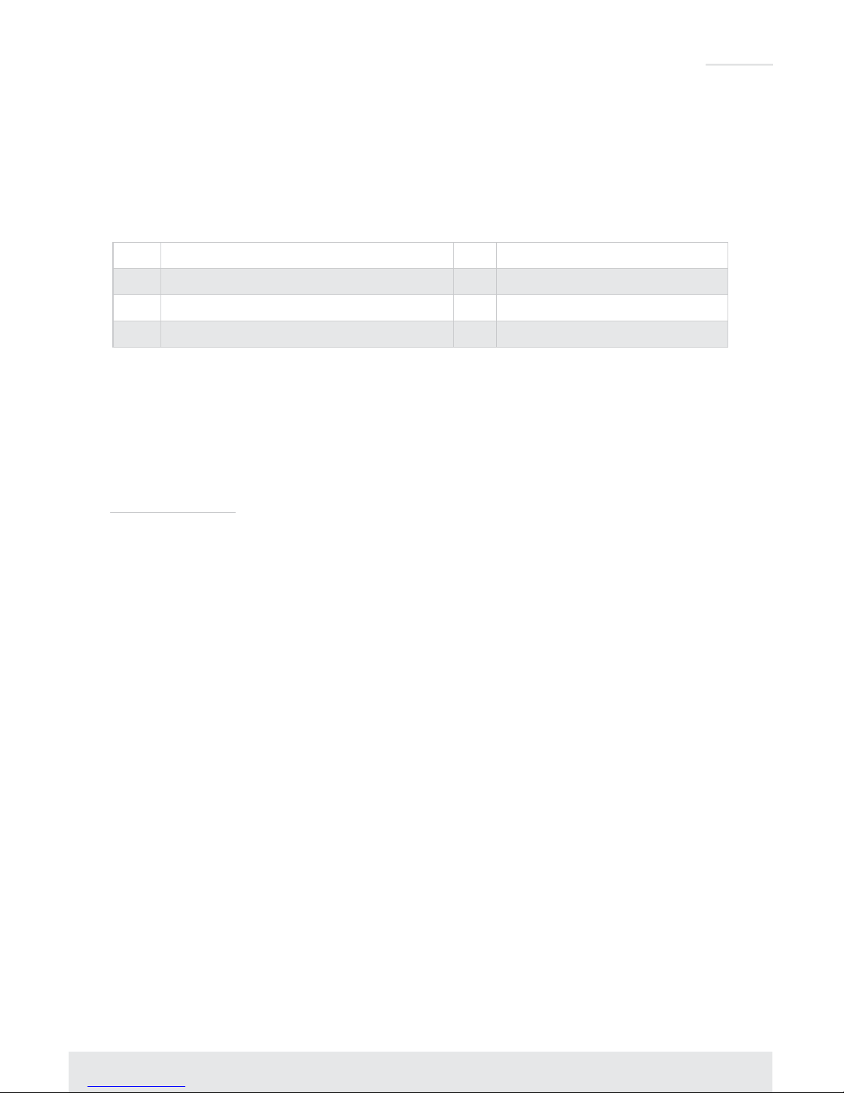
› To change the EDID settings for a particular input via IR, press the following buttons on the IR
remote control: R2, R1, R3, A, X
»
A
= Desired Input to provide EDID for. Chosen using the Input Select button from Output2
button group.
»
X
= Desired Default EDID, chosen from the below table:
No EDID Description No EDID Description
1
1080i, 2CH AUDIO
4
1920x1080 DVI
2
1080p, 2CH AUDIO (DEFAULT)
5
1920x1200 DVI
3
1280x1024 DVI
Copy EDID from Output
To copy EDID from Output “B” to input “A”, press the following buttons on the remote control:
R2, R1, R3, A, B
»
A
= Desired Input to provide EDID for. Chosen using the Input Select button from the
Output2 button group.
»
B
= Desired output to copy EDID from. Chosen using the Output1 button group.
Addressing via IR
To apply a two-digit address to your KD-MLV4x2Pro unit, press the following buttons on the
remote control:
R3, R1, R2, X1, X2
. X1 and X2 are chosen using the Device Select number pad.
» 00 is the default unit address
If a unit address other than 00 is applied, all commands via IR will require an address prefix, XX.
The address prefix is entered using the Device Select buttons. RS-232 and TCP-IP codes also
require an address prefix if an address other than 00 is applied. More information is available in
the RS-232 and TCP-IP Commands and Protocol section.
Page 14

12
Web Control Interface
The KD-MLV4x2Pro Web Control Interface provides basic and advanced setup and control
features for video, audio, and network.
To use the Web Control Interface, setup the KD-MLV4x2Pro on your Local Area Network by
connecting a network wire to the TCP-IP port located on the far-right of the back panel.
» The default TCP-IP address of the KD-MLV4x2Pro unit is
192.168.1.239
» The default port number is
23
.
You can connect to the KD-MLV4x2Pro unit on a 192.168.1.1 type router, or using a network
cable directly from your computer.
The TCP-IP address and port number of the KD-MLV4x2Pro unit can be adjusted to
accommodate your LAN’s setting. The settings are adjusted via Web Control Interface, RS-232,
or TCP/IP.
See the RS-232 and TCP-IP Commands and Protocol section for more information.
To enter the Web Control Interface, ensure that your computer is on the same network as
the KD-MLV4x2Pro or use a network cable with your computer’s network setting adjusted
to 192.168.1.xxx, open your web browser, and enter the IP address of the KD-MLV4x2Pro in
the web address cell.
192.168.1.239
KD-MLV4x2Pro
Admin Login Page
» Default password: admin
» Password may be changed in the Network Setup section of the Web Control Interface
Page 15
13
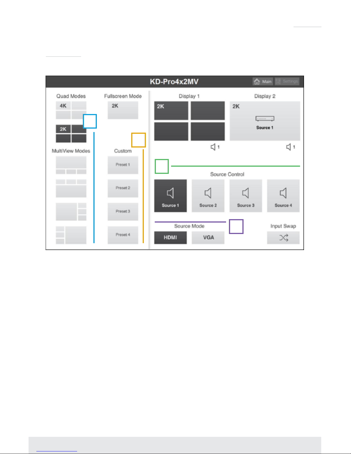
Basic Video
A
B
D
C
The Basic Video setup page enables selection of the following:
› A. Entering Quad and Multi-View modes and choosing desired layout from default presets.
» Enter Multi-View mode affects both outputs and loses independence of each output.
» The default Multi-View presets are unit presets 1-5 which can be written over manually in the
Advanced Video setup screen, or by RS-232 or TCP/IP terminal
» To swap windows, press the Input Swap button on the bottom right of the screen and each
window will rotate counter-clockwise
› B. Independent matrix switching control for outputs 1 or 2
› C. Choosing user defined manual presets 1-4, which are unit presets 6, 7, 8, and 9 respectively
and can be defined and stored in the Advanced Video setup screen or by RS-232 or TCP/IP
› D. Input type (HDMI or VGA) for Inputs 1 and 2
Page 16

14
Basic Audio
The Basic Audio setup page enables selection of the following:
› A. Input type (HDMI or external 3.5mm Stereo analog) of each audio source
› B. Selection of desired audio source for Output 1 or Output 2, independently.
Advanced Video
Page 17

15
The Advanced Video setup page enables creation of custom screen layouts and preset creation.
To create custom layouts in the Web Control Interface, the following tools are given:
› A. Window location and sizing control using 1080p (2K) Multi-view Mode Configuration tool
» An X/Y axis is used, enabling control of each pixel of the 1920x1080 screen
»
X0 / X1 range = 0 - 1919
»
Y0 / Y1 range = 0 - 1079
»
X0
= Desired location of Top-Left handle of window, from Left to Right horizontally
across the screen
»
Y0
= Desired location of Top-Left handle of window, from Top to Bottom vertically
across the screen
»
X1
= Desired location of Bottom-Right handle of window, from Left to Right horizontally
across the screen
»
Y1
= Desired location of Bottom-Right handle of window, from Top to Bottom vertically
across the screen
› B. Image priority layering using Bring to Front (Layer Setting) tool
» Available layer settings are 1-4
» 1 = Top layer / front
» 4 = Bottom layer / back
› C. Save or Apply custom layouts to presets
» Use the drop down menu to choose the desired 1080p (2K) Multi-View Custom preset
» Press the
Apply button
if you wish to set the KD-MLV4x2Pro unit’s outputs to the selected
screen layout
» Press the
Save button
if you wish to write the entered values of the Advanced Video section
to the selected screen layout using the dropdown menu.
» 1. NOTE: Saving to “Preset Quad”, “Preset Down”, “Preset Up”, “Preset Right”, or
“Preset Left” will affect the unit’s default presets called on the front panel. To restore the
default presets, a factory default setting must be applied.
» 2. Use the Window Location and Sizing Control and Image Priority Layering tools
(A and B in the previous image, respectively) to configure desired screen layout, then
press the
Save button
Page 18
16
Network Setup
A
B
D
C
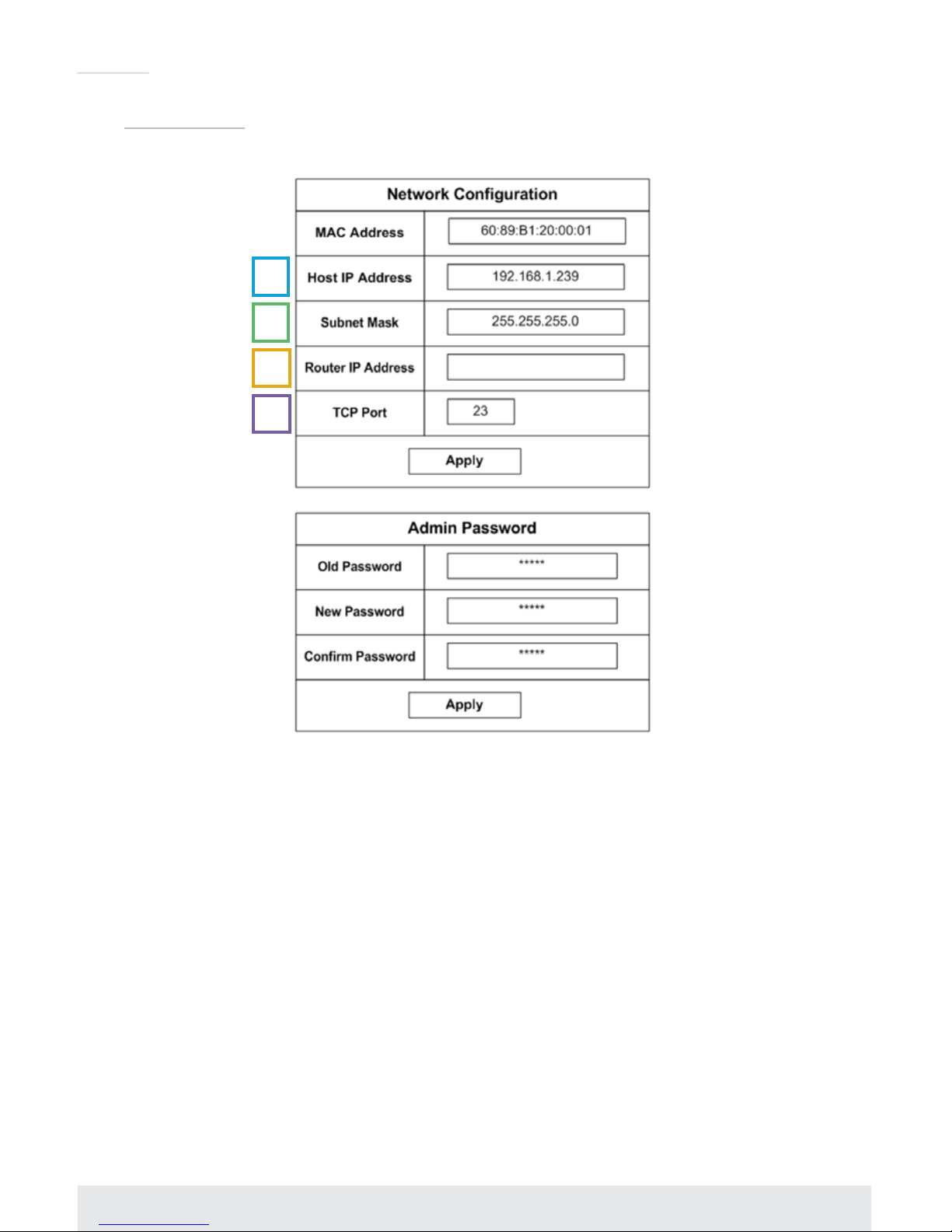
After connecting to KD-MLV4x2Pro by using a 192.168.1.xxx type network or using a crossover
cable, you can adjust and view the unit’s TCP-IP settings using the Web Control Interface.
› A. Host IP Address is the IP address that you’d like to apply to the connected KD-MLV4x2Pro
unit.
› B. Subnet mask can be adjusted to accommodate your network’s subnet
› C. Router IP Address is the IP address of the network router, AKA the Default Gateway of the
network that the KD-MLV4x2Pro is/will be on
› D. TCP Port is set to 23 by default, however it is fully adjustable, up to 9999
192.168.1.1
Page 19

17
Custom Layout Examples
To help gain comfort and familiarity with the Advanced Video setup tool, please review and
practice the follow examples.
Example 1: Full-sized background image with 3-small layered and fanned windows
Screen:
Setup:
Page 20

18
Example 2: Image layering with proportionate size decrease
Screen:
Setup:
Page 21

19
Example 3: Full-sized background window with small, right-stacked windows and
transparency applied
Note: Currently, transparency settings are only able to be applied via RS-232 or TCP-IP terminal.
See the RS-232 Commands and Protocol and Window Transparency and Border settings section
for more information.
» Example 3 depicts a 25% transparency setting applied to inputs
» In addition to transparency, a custom border may be applied to each window via RS-232
or TCP-IP terminal.
Screen:
Setup:
Page 22
20
RS-232 and TCP-IP Commands and Protocol
RS-232 Protocol:
The KD-MLV4x2Pro provides access to all functions when used with an RS-232 control system.
› Baud Rate = 57600 bits per second
› Data Bits = 8
› Stop Bits = 1
› Parity = None
› Flow Control = None
› Carriage Return: Required
› Line Feed: Required
› Commands are not case-sensitive.
Spaces shown below may be excluded.
› Carriage return and line feed is required at the end of each string.
TCP/IP Setup:
› The default TCP-IP address is 192.198.1.239
» You can connect to the unit on a 192.168.1.xxx type network, or using a crossover cable
» If you are not using a 192.168.1.1 type network, you can adjust the TCP-IP address and
port number settings via RS-232 to your desired network setup, and then connect to the
unit.
› The default TCP-IP port number is 23
› Control commands are exactly the same via TCP-IP as they are via RS-232
Response from Help command
–
List and description of all available RS-232 / TCP-IP commands:
KD-MLVX4x2Pro>h
-------------------------------------------------------------------------
-- Key Digital Systems HELP --
-------------------------------------------------------------------------
-- KD-MLV4x2Pro System Address = 00 F/W Version : 1.05 --
-- --
-- Azz : All Commands start by Prex System Address zz, if [01-99] --
-- H : Help --
-- STA : Show Global System Status --
-- --
-- Video Input Setup Command ( xx=[01~04], y=[1~2] ) --
-- SPI xx VS y : Set Input xx by Video Source y [1=HDMI, 2=VGA] --
-- SPIA VS y : Set All Input by Video Source y [1=HDMI, 2=VGA] --
-- SPI xx AS y : Set Input xx by Audio Source y [1=HDMI, 2=Ext. Audio] --
-- SPIA AS y : Set All Input by Audio Source y [1=HDMI, 2=Ext. Audio]--
-- SPI xx VT y : Set VGA Input xx by Video Type y [1=VGA, 2=YPbPr] --
-- SPIA VT y : Set All VGA Input by Video Type y [1=VGA, 2=YPbPr] --
-- --
-- Video Output Setup Command --
-- ( xx=[01~02], yy=[01~06,05=4K, 06=2K QUAD Multiview], z=[1~2] )--
-- SPO xx SI yy : Set Output xx to Video Input yy --
-- SPOA SI yy : Set All Outputs to Video Input yy --
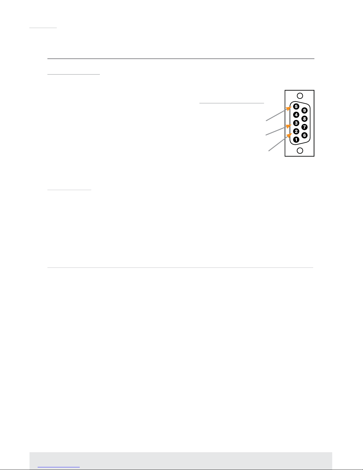
Pin 5 – Ground
Pin 3 – Receive
Pin 2 – Transmit
RS-232 cable pin out
Page 23

21
-- SPO xx ON/OFF : Set Output xx ON or Set Output xx OFF --
-- SPOA ON/OFF : Set All Outputs ON or Set All Outputs OFF --
-- SPO xx DBG ON/OFF: Set Outputs xx Debug Mode ON/OFF --
-- SPOA DBG ON/OFF : Set Outputs xx Debug Mode ON/OFF --
-- SPO MV z : Set Outputs by z [1=Normal, 2=Mutliview Mode] --
-- --
-- Audio Output Setup Commands: ( xx=[01~02], [E=Enable, D=Disable] ) --
-- SPO xx SA yy : Set Output xx Audio by Input yy [yy=01~04] in M/V --
-- SPOA SA yy : Set All Output xx Audio by Input yy [yy=01~04] in M/V--
-- SPO xx HA E/D : Set HDMI Audio Output xx E/D --
-- SPOA HA E/D : Set All HDMI Audio Outputs E/D --
-- SPO xx DA E/D : Set External Digital PCM Output xx E/D --
-- SPOA DA E/D : Set All External Digital PCM Outputs E/D --
-- --
-- Multiview Mode Setup Command ( z=[1~9] ) --
-- [1=QUAD, 2=DOWN, 3=UP, 4=RIGHT, 5=LEFT, 6~9=MANUAL1~4] --
-- SPM VIS : Set Input Swap --
-- SPM VSS z : Save User Screen Mode to z, (z=[1~9]) --
-- SPM VSM z : Set Predened Screen Mode z at 2K Multiview Mode --
-- --
-- Multiview Screen Manual Setup Command --
-- ( vv=[01~04], aaaa=[0000~1919], bbbb=[0000~1079] ) --
-- ( cccc=[0000~1919], dddd=[0000~1079], z=[0~9] ) --
-- SPM vv XY aaaa.bbbb.cccc.dddd : Set Start of X/Y-axis by aaaa/bbbb- and End of X/Y-aixs by cccc/dddd on the Output Screen for Input vv--
-- SPM TY z : Set Transparency by z [0=00%, 1=25%, 2=50%, 3=75%] --
-- SPM BLW z : Set Border Line Width by z [0=None, 1~9Pixels] --
-- SPM BLC rrr.ggg.bbb : Set Border Line Color by RED/GREEN/BLUE --
-- ( rrr=[001~255], ggg=[001~255], bbb=[001~255] ) --
-- SPM PT abcd : Set Priority of Inputs by abcd [1234~4321] --
-- --
-- EDID Setup Command ( xx=[01~04], yy=[01~02], zz=[01-05] ) --
-- SPCEDID xx H yy : Copy EDID from Ouput yy to Input xx --
-- SPCEDIDA H yy : Copy EDID from Ouput yy to All Inputs --
-- SPCEDID xx D zz : Copy EDID from Default EDID zz to Input xx --
-- SPCEDIDA D zz : Copy EDID from Default EDID zz to All Inputs --
-- DEFAULT EDID 01 : HDMI Video 1080i@60, Audio 2CH PCM --
-- DEFAULT EDID 02 : HDMI Video 1080p@60, Audio 2CH PCM --
-- DEFAULT EDID 03 : DVI Video Max. 1280x720@60, No Audio --
-- DEFAULT EDID 04 : DVI Video Max. 1280x1024@60, No Audio --
-- DEFAULT EDID 05 : DVI Video Max. 1920x1080@60, No Audio --
-- --
-- System Control Setup Commands: --
-- SPCFB E/D : Set Front Panel Buttons E/D (E=Enable,D=Disable) --
-- SPCFD ON/OFF : Set Front LCD Backlight and LEDs ON/OFF --
-- SPCDF : Reset to Factory Defaults --
-- SPCDF00 : Reset to Factory Defaults Except of Network Setting --
-- --
-- Network Setup, ( xxx=[000-255], zzzz=[0001~9999] ) --
-- SPCETIPA xxx.xxx.xxx.xxx : Set Host IP Address to xxx.xxx.xxx.xxx --
-- SPCETIPM xxx.xxx.xxx.xxx : Set Net Mask to xxx.xxx.xxx.xxx --
Page 24

22
-- SPCETIPR xxx.xxx.xxx.xxx : Set Route IP Address to xxx.xxx.xxx.xxx --
-- SPCETIPP zzzz : Set TCP/IP Port to zzzz --
-- --
-- System Address Setup Command: xx = [00-99], 00 = Single --
-- SPCAxx : Set System Address to xx --
Response from Help command
– Current settings and/or status of unit:
KD-MLVX4x2Pro>sta
-------------------------------------------------------------------------
-- Key Digital Systems STATUS --
-------------------------------------------------------------------------
-- KD-MLVX4x2Pro System Address = 00 F/W Version : 1.05 --
-- --
-- RS232 : Baud Rate=57600bps, Data=8bit, Parity=None, Stop=1bit --
-- Front Panel Button : Enable --
-- Front LCD Display Backlight : ON --
-- --
-- Network Setting(Telnet Server) Status --
-- MAC Address = 60:89:b1:20:00:01 --
-- Host IP Address = 192.168.001.239 --
-- Net Mask = 255.255.255.000 --
-- Router IP Address = 192.168.001.001 --
-- TCP Port = 0023 --
-- --
-- Video Input Status --
-- 01: EDID = DEFAULT02, Link = ON , Video = HDMI , Audio = HDMI --
-- 02: EDID = DEFAULT02, Link = ON , Video = HDMI , Audio = HDMI --
-- 03: EDID = DEFAULT02, Link = ON , Video = HDMI , Audio = HDMI --
-- 04: EDID = DEFAULT02, Link = ON , Video = HDMI , Audio = HDMI --
-- --
-- Video Output Status --
-- 01: Input = 01(2K Full Screen ), Link = ON , Output = ON --
-- 02: Input = 01(2K Full Screen ), Link = ON , Output = ON --
-- --
-- Audio Output Status --
-- 01: Input = 01, HDMI = Enable , External PCM = Enable , Debug = OFF --
-- 02: Input = 01, HDMI = Enable , External PCM = Enable , Debug = OFF --
-- --
-- Multiview Mode Status --
-- Predened Screen Mode = QUAD --
-- Transparency = 00% , Border Line = 0, Priority = 1234 --
-- --
-- Multiview Screen Manual Setup Command --
-- 01: SX = 0000, SY = 0000, EX = 0959, EY = 0539, Priority = 1 --
-- 02: SX = 0960, SY = 0000, EX = 1919, EY = 0539, Priority = 2 --
-- 03: SX = 0000, SY = 0540, EX = 0959, EY = 1079, Priority = 3 --
-- 04: SX = 0960, SY = 0540, EX = 1919, EY = 1079, Priority = 4 --
Page 25
23
Window Transparency and Border Settings
In addition to the possible custom settings applied using the Advanced Video screen of the Web
Control Interface, window transparency and border settings can be applied to all windows in 4K or
2K Quadrant Modes, as well as 2K Multi-View mode.
At the time of introduction, window Transparency and Border settings can only be applied / viewed
via RS-232 or TCP-IP terminal. Please see the RS-232 and TCP-IP Commands and Protocol
section for additional information
Transparency
While in 4K or 2K Quadrant Modes, as well as 2K Multi-View mode, transparency can be applied
to the source windows, allowing windows in the back (ie. Layer 4) to be viewable through windows
in the front (ie. Layer 2, 3, or 4) of a custom layout.
› Transparency settings are not independent for each window.
› The possible transparency setting applied to each window is 0%, 25%, 50%, and 75%
› The RS-232 / TCP-IP command to apply transparency is as follows:
»
SPM TY z
› Set Transparency by z [0=00%, 1=25%, 2=50%, 3=75%]
Window Border
KD-MLV4x2Pro enables a border-line / bezel to be applied and customized if desired. The borderline width and color of the border-line can be specified
› The RS-232 / TCP-IP command to apply border-line width is as follows:
»
SPM BLW z
› Set Border Line Width by z [0=None, 1~9Pixels]
› The RS-232 / TCP-IP command to apply the desired color to the border-line is as follows:
»
SPM BLC rrr.ggg.bbb
» Set Border Line Color by RED/GREEN/BLUE
» (rrr=[001~255], ggg=[001~255], bbb=[001~255]
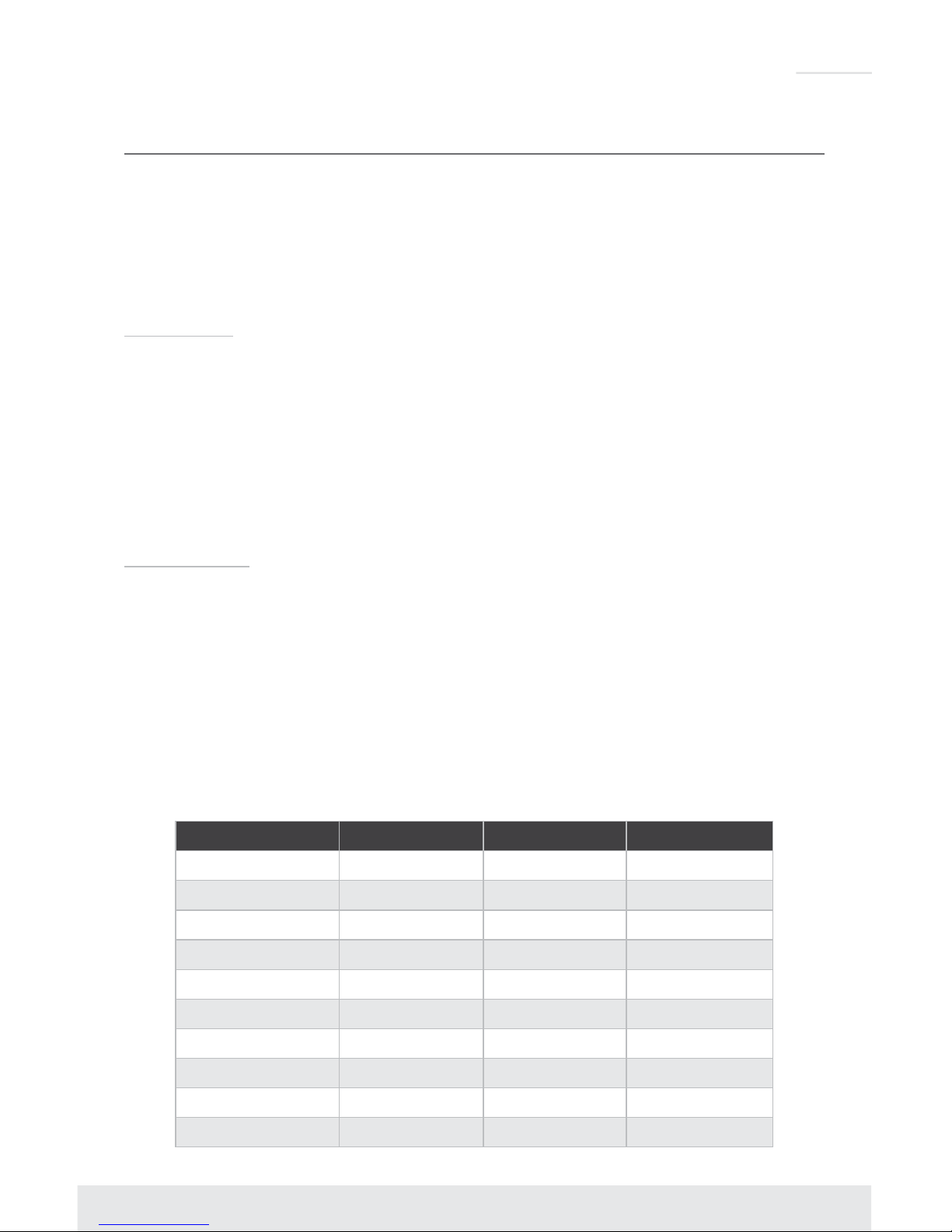
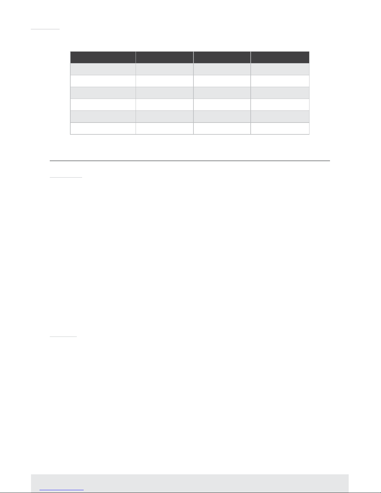
› Color-picker reference values:
Color rrr value ggg value bbb value
Red 255 0 0
Orange 255 165 0
Gold 255 215 0
Light Blue 173 216 230
White 255 255 255
Black 0 0 0
Purple 128 0 128
Navy Blue 0 0 128
Royal Blue 65 105 255
Yellow 255 255 0
Page 26
24
Color rrr value ggg value bbb value
Teal 0 128 128
Blue 0 0 255
Brown 139 68 19
Maroon 128 0 0
Silver 192 192 192
Green 0 128 0
Specifications
Technical:
» Inputs: 4 HDMI connectors, Type A, 19 pin female; 2 HD analog video 15-pin female,
4 analog audio connector, 3.5mm stereo female
» Outputs: 1 HDMI connector, Type A, 19 pin female; 1 HDBaseT RJ45 female; 2 digital
coaxial audio on RCA connector, female, follows SPDIF format IEC 60958; 2 Analog
balanced/unbalanced 6-pin terminal block
» TMDS Bandwidth: 9 Gb/s total
» Deep Color Support: Supports digital video formats in Deep Color Mode up to 8 bits/color
with all HDMI and HDCP technologies
» Link: Single Link
» DDC Signal (Data): Input DDC signal – 5 Volts p-p (TTL)
» HDMI Video/Audio Signal: 1.2 Volts p-p
» DDC Communication: EDID And HDCP buffering between source and display
» Wired IR: Modulated IR signal input, 0-5V TTL or -10 to +10V, 3.5mm mono female
connector with signal on tip
» Power: External power supply; 12V/3A
General:
» Regulation: CE, RoHS, WEEE
» Enclosure: Black metal
» Rack Mount: 1U, full rack-width (rack ears included)
» Accessories: Rack Ears
» Product: 17.25” x 8.875” x 1.75”; Weight: 6.5 lbs
» Packaging: 18.5” x 13” x 3.5”; Weight: 8.8 lbs
Page 27
25
Important Product Warnings:
1. Connect all cables before providing power to the unit.
2. Test for proper operation before securing unit behind walls or in hard to access spaces.
3. If installing the unit into wall or mounting bracket into sheet-rock, provide proper screw support
with bolts or sheet-rock anchors.
Safety Instructions:
Please be sure to follow these instructions for safe operation of your unit.
1. Read and follow all instructions.
2. Heed all warnings.
3. Do not use this device near water.
4. Clean only with dry cloth.
5. Install in accordance with the manufacturer’s instructions.
6. Do not install near any heat sources such as radiators, heat registers, stoves, or other
apparatus (including amplifiers) that produce heat.
7. Only use attachments/accessories specified by the manufacturer.
8. Refer all servicing to qualified service personnel. Servicing is required when the device has
been damaged in any way including:
» Damage to the power supply or power plug
» Exposure to rain or moisture
Power Supply Use:
You MUST use the Power Supply provided with your unit or you VOID the
Key Digital® Warranty and risk damage to your unit and associated equipment.
Page 28

26
How to Contact Key Digital
®
System Design Group (SDG)
For system design questions please contact us at:
› Phone: 914-667-9700
› E-mail: [email protected]
Customer Support
For customer support questions please contact us at:
› Phone: 914-667-9700
› E-mail: [email protected]
Technical Support
For technical questions about using Key Digital® products, please contact us at:
› Phone: 914-667-9700
› E-mail: [email protected]
Repairs and Warranty Service
Should your product require warranty service or repair, please obtain a
Key Digital® Return Material Authorization (RMA) number by contacting us at:
› Phone: 914-667-9700
› E-mail: [email protected]
Feedback
Please email any comments/questions about the manual to:
› E-mail: [email protected]
Warranty Information
All Key Digital® products are built to high manufacturing standards and should provide years of
trouble-free operation. They are backed by a Key Digital Limited 3 Year Product Warranty Policy.
http://www.keydigital.com/warranty.htm
Page 29
Key Digital®, led by digital video pioneer Mike Tsinberg,
develops and manufactures high quality, cutting-edge
technology solutions for virtually all applications where
high-end video and control are important. Key Digital
®
is at the forefront of the video industry for Home Theater
Retailers, Custom Installers, System Integrators,
Broadcasters, Manufacturers, and Consumers.
Key Digital® Systems :: 521 East 3rd Street :: Mount Vernon, NY 10553
Phone : 914.667.9700 Fax : 914.668.8666 Web : www.keydigital.com
Rev 0 – Aug 2017
 Loading...