

Page 1
Rev 0 – Dec 2017
KD-MAX8x8
8x8 Audio Matrix Switcher with built-in Audio DSP
Operating Instructions
Key Digital®, led by digital video pioneer Mike Tsinberg,
develops and manufactures high quality, cutting-edge
technology solutions for virtually all applications where
high-end video and control are important. Key Digital
is at the forefront of the video industry for Home Theater
Retailers, Custom Installers, System Integrators,
Broadcasters, Manufacturers, and Consumers.
Key Digital® Systems :: 521 East 3rd Street :: Mount Vernon, NY 10553
Phone : 914.667.9700 Fax : 914.668.8666 Web : www.keydigital.com
®
The Experts in Digital Video Technology and Solutions
™
Page 2
4 1
Table of Contents
Introduction ................................................................ 1
Connections, Buttons and LEDs ................................................ 2
Application Example ......................................................... 5
Quick Setup Guide .......................................................... 6
Settings and Adjustments via Remote ............................................ 6
RS-232 and TCP/IP Commands . . . . . . . . . . . . . . . . . . . . . . . . . . . . . . . . . . . . . . . . . . . . . . . . 9
Expansion Configurations .................................................... 12
Specifications ............................................................. 13
Important Product Warnings & Safety Instructions .................................. 14
®
How to Contact Key Digital
Warranty Information ........................................................15
Note: Please visit www.keydigital.com for the latest product documentation and software
downloads. Product features and specifications are subject to change without notice.
.................................................. 15
Introduction
Key Digital® KD-MAX8x8 is an 8x8 matrix of analog and digital audio. Inputs and outputs support
balanced or unbalanced analog audio on a 6-pin phoenix connector while digital PCM audio
up to 5.1 channels is supported on RCA connectors. Analog and digital outputs may listen to
independent selections of the connected audio sources and each output features a digital signal
processor for volume, muting, 3-band EQ, balance, and delay. Systems greater than 8x8 may be
achieved using multiple units.
Key Features
› Multi-format Audio Multiplexing: DSP per output for independent matrix selection
» Analog to Analog Matrix with DSP
» Digital to Analog Matrix with DSP
» Digital to Digital Matrix
» Analog to Digital Matrix
› Audio DSP: Variable level settings for volume, muting, 3-band EQ, balance, and lip-sync delay
per balanced output
› Audio Delay: Variable level set from 0ms to 170ms
› Audio Conversion: Analog to digital. Digital to analog
› Balanced or Unbalanced: Input audio type may be specified per input
› Lossless Compressed Digital Audio: Dolby
› Long Cable Runs: Enabled by balanced audio connection, signals may be run up to 1,000 ft.
› Expansion Configurations: Custom configurations available for incrementally expansion using
multiple units
» Up to 8 sources/inputs with up to 64 zones/outputs
» Up to 16 sources/inputs with up to 64 zones/outputs
» Up to 24 sources/inputs with up to 32 zones/outputs
» Up to 32 sources/inputs with up to 32 zones/outputs
› Control Integration: TCP/IP, RS-232, and USB with full bi-directional operation, front panel push
buttons and LEDs, front/rear optical IR, serial IR,
› Control System Support: Key Digital
ready. Fully controllable by all IR, RS-232, and TCP/IP supported control systems via open API:
®
AMX
, Crestron®, Control4®, KNX®, RTI®, Savant, URC®, Leviton® etc.
› Key Digital
Digital
®
App Ready: Scan & detect population for pre-built GUI and TCP/IP control via Key
®
App
Accessories
› Power supply: +12V/2A (25W), model KD-PS12V2ASC
› IR Remote control, model KD-REMOTEHM88
› (17) 6-position terminal block
› Rack mount ears
Rack Mounting
› Secure the included rack ears to each side of KD-MAX8x8 with the supplied hardware, then
fasten the unit to the rack rails with appropriate machine screw.
®
and DTS surround up to 5.1ch pass-thru
®
App ready, Compass Control® Pro ready, KD-Wizard®
Page 3
2 3
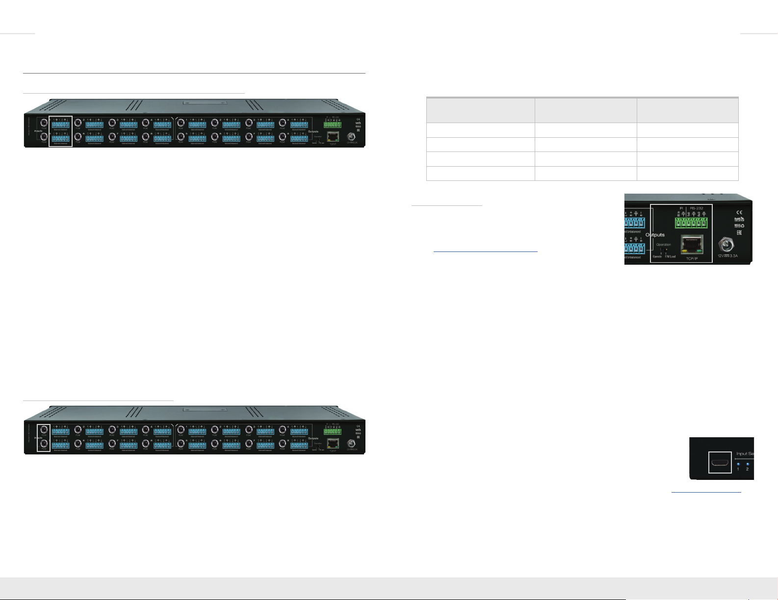
Connections, Buttons and LEDs
Balanced/Unbalanced Analog Audio Inputs and Outputs
› Each output and input features one analog audio connector on 6-pin phoenix connector for
balanced or unbalanced audio
› Pin assignment for Analog Audio connections:
» Left + is Pin 1; Left Ground is Pin 2; Left - is Pin 3
» Right + is Pin 4; Right Ground is Pin 5; Right - is Pin 6
› Unbalanced audio is the default type for each input, and should be connected using the positive
(+) and ground pins.
› Each input and accepts/drives audio signals up to 2VRMS with a sampling rate of 48KHz
› Each output features an assortment of DSP controls including Volume, Muting, 3-band EQ, and
Lip-sync delay.
› There are no down/up conversion capabilities. For example, a 2ch analog audio input cannot be
converted to 5.1 surround.
› Microphone inputs are not directly supported. To integrate microphones, please use external
powered mixer.
› Each input may be individually set so that analog is the associated type.
» If the associated input type is set to analog, the output selecting the source will output the
analog feed on both the analog and PCM output connectors.
» The default association type for each input is “both”:
» Analog In to Analog Out
» PCM In to PCM Out
PCM Digital Audio Inputs and Outputs
› Each output and input channel features one digital audio on an RCA connector
› Compatible with SPDIF format IEC 60958 supporting 2CH PCM, Dolby 5.1ch, DTS 6.1ch
› Compatible with sampling rates up to 192KHz
› Each input may be individually set so that analog is the associated type.
» If the associated input type is set to analog, the output selecting the source will output the
analog feed on both the analog and PCM output connectors.
» The default association type for each input is “both”:
» Analog In to Analog Out
» PCM In to PCM Out
› There are no DSP features on the digital audio inputs or outputs. However, muting settings do
apply.
› There are no down/up conversion capabilities:
Audio Input
Signal Format
Audio L/R
Output
Digital Audio
Output
2CH PCM Pass-through Pass-through
Multi-Channel PCM MUTE MUTE
DOLBY/DTS MUTE Pass-through
HD Audio MUTE MUTE
Unit Control Ports
› MAIN Control Port
» 6-Pin Terminal Block for IR and RS-232
» RS-232 and TCP/IP commands may be found in the
RS-232 & TCP/IP Commands section
» Pin out:
» Pin 1 = IR Signal
» Pin 2 = IR Ground
» Pin 3 = RS-232 Tx Data
» Pin 4 = RS-232 Ground
» Pin 5 = RS-232Rx Data
» Pin 6 = Ground (optional)
› TCP/IP Control Port
» Default static IP address is 192.168.1.239
» Connect an Ethernet cable from the KD-MAX8x8 to a network router or connect a straight-
through cable directly from a PC
› Firmware Mode Switch
» Should remain in Operation setting unless instructed by Key Digital technical support
» If changing position of switch, do so only with unit not powered
» Not every firmware update requires the switch to be set to the F/W Load position
» If set to F/W Load, all front LEDs will be illuminated, indicating that
unit is in bootloader mode and awaiting a firmware load.
› Micro USB (front panel)
» Typically used for unit configuration, control, and firmware updates
» It is most commonly used with KD-Wizard
®
software downloaded at www.keydigital.com
Page 4

4 5
Ethernet
x2
RS-232
IR/RS232
KD-MAX8x8
WiFi Router
RJ45
RJ45
WiFi
Enterprise Software License
for Compass Control
®
Pro
Supports iOS & Android
KD-ProCL8
KD-ProCL6
KD-ProCL4
KD-ProCL1
KD-ProCL1
KD-MC1000
Master Controller
Zone 1
KD-AMP220
Input Control
Vol
Mic
Mute
Line BassL/R PCM
1
2
Treble
KD-AMP220
Zone 5
KD-AMP220
Input Control
Vol
Mic
Mute
Line BassL/R PCM
1
2
Treble
KD-AMP220
Zone 2
KD-AMP220
Input Control
Vol
Mic
Mute
Line BassL/R PCM
1
2
Treble
KD-AMP220
Zone 6
KD-AMP220
Input Control
Vol
Mic
Mute
Line BassL/R PCM
1
2
Treble
KD-AMP220
Zone 3
KD-AMP220
Input Control
Vol
Mic
Mute
Line BassL/R PCM
1
2
Treble
KD-AMP220
Zone 7
KD-AMP220
Input Control
Vol
Mic
Mute
Line BassL/R PCM
1
2
Treble
KD-AMP220
Zone 4
KD-AMP220
Input Control
Vol
Mic
Mute
Line BassL/R PCM
1
2
Treble
KD-AMP220
Zone 8
KD-AMP220
Input Control
Vol
Mic
Mute
Line BassL/R PCM
1
2
Treble
KD-AMP220
Digital Media Streamer
Blu-Ray
Cable
Satellite
Media Server
DVD
Apple TV
L/R
L/R
PCM
PCM
PCM
PCM
PCM
PCM
Sat Radio
PCM / L/R
Buttons and LEDs
› 8 output buttons on the front panel
» Pressing an output button will select the input
» A blue LED indicates selected input for each output
› Output MUTE is indicated by the outermost (1, 2, 7, 8) LEDs illuminated,
while the inner LEDs (3, 4, 5, 6) are NOT illuminated
› Output OFF is indicated when the innermost (3, 4, 5, 6) LEDs are illuminated,
while the outermost (1, 2, 7, 8) are NOT illuminated
› Factory default reset is achieved by simultaneously holding the input select buttons 1&8
for 10 seconds
» The matrix reboots after reset. The LEDs will ramp until reboot has completed
Application Example
Page 5

6 7
1 2 3
4 5 6
7 8 9
0
All Mute
Volume
Mute
Audio ModeVideo Mode
Balance LipSync
Bass Middle Treble
Restore
All Restore
R1 R2
R3 R4
Power Off
Power On
www.keydigital.com
Tone Controls
Quick Setup Guide
1. Begin with the KD-MAX8x8 and all Input/Output devices turned off and power cables removed
2. Connect analog audio sources to the desired 6-pin phoenix terminals and/or digital audio
sources to the desired PCM inputs
3. Connect the analog audio output amplifiers/receivers via the analog 6-pin phoenix terminals
and digital destinations via the PCM outputs
4. Connect power to the KD-MAX8x8, followed by all other input and output devices and turn
them on
5. If balanced audio input type is required for any of the analog inputs, set the desired input via
the IR remote control using command sequence R2, XX, Audio Mode, 3. Note that XX is the
desired input number (01 – 08).
6. Operate KD-MAX8x8 switcher via the front panel buttons, IR remote, serial IR or RS-232
control
7. See TCP/IP and RS-232 Commands or Settings and Adjustments via Remote sections for
more adjustments options
Settings and Adjustments via Remote
Many initial installation steps may be configured using the factory remote control. Other advanced
settings may be configured using USB and software downloaded from www.keydigital.com
Input Associated Audio Type
» IR Button Sequence = R2, XX, Video Mode, Y
» XX = Input # [01-08]
» Y = Audio Type [1 = Analog, 2 = PCM, 3 = Analog to Analog,
PCM to PCM]
Analog Input Audio Type
» IR Button Sequence = R2, XX, Audio Mode, Y
» XX = Input # [01-08]
» Y = Audio Type [1 = L+/R+, 2 = L-/R-, 3 = Balanced, 4 = N/C]
Matrix Switching Command (Associated Audio)
» IR Button Sequence = Audio Mode, X, Y
» X = Output # [1-8]
» Y = Input # [1-8]
Output Mute/Un-mute
» IR Button Sequence = R1, X, Mute/Restore
» X = Output # [1-8]
Output Volume Up/Down
» IR Button Sequence = R1, X, Volume, Up/Down
» X = Output # [1-8]
Output Volume Level
» IR Button Sequence = R1, X, Volume, YY
» X = Output # [1-8]
» YY = Volume Level [00-99]
Set Unit Static IP Address to xxx.xxx.xxx.xxx
» IR Button Sequence = R3, Bass, XXX, Video Mode, XXX, Video Mode, XXX,
Video Mode, XXX
Set Unit Default Gateway/Router IP Address to xxx.xxx.xxx.xxx
» IR Button Sequence = R3, Treble, XXX, Video Mode, XXX, Video Mode, XXX,
Video Mode, XXX
» Default IP address is 192.168.1.239, with default port 23 and default gateway 192.168.1.1
» Please see the IR Remote Command List section for additional commands
Apply New Network Configuration
» IR Button Sequence = R3, All Restore
IR Remote Command List
IR Control is possible using remote model KD-REMOTEHM88 (included). Use the numerical
keypad for X, Y, and Z values below.
Advanced unit setup should be completed in the KD Wizard software found on
www.keydigital.com
Command Sequence
Input Setup
Parameters XX = input # (01-08)
Input associated input type R2, XX, Video Mode, Y
Y = 1 (Analog) / 2 (PCM) / 3 (both)
Set analog input type R2, XX, Audio Mode, Y
Y = [1 = L+/R+, 2 = L-/R-, 3 = Balanced, 4 = N/C]
Audio Output Setup
Parameters XX = 01 – 08
YY = 01 – 99, Up, Down
Set Output X to Association Input Y Audio Mode, X, Y
X = Output #[1-8]
Y = Input #[1-8]
Set analog + digital output XX = Analog input YY R1, XX, Video Mode, YY
Set analog + digital output XX = PCM input YY R1, XX, R2, YY
Set PCM output XX = PCM input YY R1, XX, R3, YY
Set ALL output Mute/Unmute All Mute/All Restore
Set output XX ON/OFF R1, XX, R4, 1/0
Page 6

8 9
Output DSP
Parameters X = 1 – 8, 01-08
YY = 00 – 99*, Up, Down
*unless otherwise noted
Set output X to volume YY R1, X, Volume, YY
Set output X balance YY R1, X, Balance, YY (00 – 40, 20 is default)
Set output X Bass YY R1, X, Bass, YY (00 – 24, 12 is default)
Set output X Mid YY R1, X, Middle, YY (00 – 24, 12 is default)
Set output X Treble YY R1, X, Treble, YY (00 – 24, 12 is default)
Set output X Delay YY R1, X, LipSync, YY (00 – 99, 00 is default)
Set output X Mute/Unmute R1, X, Mute/Restore
Network Setup
Parameters XX = 000 - 255
YY = 0001 - 9999
Set Host IP Address to xxx.xxx.xxx.xxx R3, Bass, XXX, Video Mode, XXX, Video Mode, XXX, Video
Mode, XXX
Set Net Mask to xxx.xxx.xxx.xxx R3, Middle, XXX, Video Mode, XXX, Video Mode, XXX,
Video Mode, XXX
Set Router IP Address to xxx.xxx.xxx.xxx R3, Treble, XXX, Video Mode, XXX, Video Mode, XXX,
Video Mode, XXX
Set TCP/IP Port to zzzz R3, Volume, XXXX
Apply New Network Config R3, All Restore
RS-232 and TCP/IP Commands
KD-MAX8x8 allows control over serial interface for bi-directional
communication.
Use pins 3, 4, 5 for RS-232 communication.
In addition to RS-232, the serial interface may also be accessed
using a TCP/IP connection.
» Default IP address is 192.168.1.239, with default port 23
Connection Protocol:
» Baud Rate = 57,600 bits per second
» Data Bits = 8
» Stop Bits = 1
» Parity = None
» Flow Control = None
» Carriage Return: Required
Notes
» Commands are not case-sensitive
» Spaces are shown for clarity; commands should NOT have any spaces
» After a new command is received, a prompt should be sent back
Response from Help command
KD-MAX8x8> H
-------------------------------------------------------------------------
-- Key Digital Systems HELP --
-------------------------------------------------------------------------
-- KD-MAX8x8 System Address = 00 F/W Version : 1.0 --
-- --
-- PN : Power On --
-- PF : Power Off --
-- Azz : All Commands start by Prex System Address zz, if [01-99]--
-- H : Help --
-- STA : Show Global System Status --
-- --
-- Audio Input Setup Command ( xx=[01~08,A] A=All, y=[1~2] ) --
-- SPIxx AS y : Set Analog Input xx by y [1=L+/R+, 2=L-/R-, 3=Balanced]--
-- SPIxx AA y : Set Audio Association of Input xx by y --
-- y [1=Analog, 2=PCM, 3=Both(Analog->Analog, PCM->PCM)] --
-- SPIxx WN cccccccccccccccc : Save Name of Input xx --
-- SPIxx RN : Read Name of Input xx --
-- --
-- Audio Output Setup Command ( xx=[01~08,A=All], yy=[01~08] ) --
-- SPOxx SI yy : Set Output xx to Association Input yy --
-- SPOxx SA yy : Set Output xx to Analog Input yy --
-- SPOxx SP yy : Set Output xx to PCM Input yy --
-- SPOxx SB yy : Set PCM Output xx to PCM Input yy --
-- SPOxx D E/D : Set Output xx Disconnection Enabled/Disabled --
-- SPOxx WN cccccccccccccccc : Save Name of Output xx --
-- SPOxx RN : Read Name of Output xx --
-- --
–
Returns entire API in readable format:
Page 7

10 11
-- Audio DSP Setup Command ( xx=[01~08,A] A=All ) --
-- SPOxx AV yy : Set Output xx Audio Volume to yy, yy=[00-99],U,D--
-- SPOxx AB yy : Set Output xx Audio Balance to yy, yy=[00-40],U,D--
-- SPOxx AL yy : Set Output xx Audio Bass Gain to yy, yy=[00-24],U,D--
-- SPOxx AM yy : Set Output xx Audio Middle Gain to yy, yy=[00-24],U,D--
-- SPOxx AH yy : Set Output xx Audio Treble Gain to yy, yy=[00-24],U,D--
-- SPOxx AD yy : Set Output xx Audio Delay to yy, yy=[00-99],U,D--
-- SPOxx A E/D/T : Set Output xx Audio Mute Enabled/Disabled/Toggle --
-- --
-- Network Setup Command ( xxx=[000-255], zzzz=[0001~9999] ) --
-- SPCETIPA xxx.xxx.xxx.xxx : Set Host IP Address to xxx.xxx.xxx.xxx --
-- SPCETIPM xxx.xxx.xxx.xxx : Set Net Mask to xxx.xxx.xxx.xxx --
-- SPCETIPR xxx.xxx.xxx.xxx : Set Route IP Address to xxx.xxx.xxx.xxx --
-- SPCETIPP zzzz : Set TCP/IP Port to zzzz --
-- SPCETIPB : Apply New Network Cong --
-- --
-- System Control Setup Command ( xx=[01-99], z=[0-4] ) --
-- SPC NI xx : Set Number of Inputs for Expansion Matrix Switch --
-- SPC NO xx : Set Number of Ouptus for Expansion Matrix Switch --
-- SPC EX xx : Set Unit Number for Expansion Matrix Switch --
-- SPCFB E/D : Set Front Panel Button E/D (E=Enable,D=Disable) --
-- SPC RSB z : Set RS232 Baud Rate to z bps --
-- [0:57600, 1:38400, 2:19200, 3:9600, 4:4800] --
-- SPCDF : Reset to Factory Default All --
-- --
-- System Address Setup Command ( xx = [00-99], 00 = Single ) --
-- SPCAxx : Set System Address to xx --
-------------------------------------------------------------------------
Status Command (STA)
KD-MAX8x8> STA
-------------------------------------------------------------------------
-- Key Digital Systems STATUS --
-------------------------------------------------------------------------
-- KD-MAX8x8 System Address = 00 F/W Version : 1.0 --
-- --
-- Expansion Matrix Switch : Input = 08, Output = 08, Unit Number = 0 --
-- --
-- RS232 : Baud Rate=057600bps, Data=8bit, Parity=None, Stop=1bit --
-- Front Panel Button : Enabled
--
-- --
-- Network Setting(Telnet Server) Status --
-- MAC Address = 60:89:B1:14:00:02 --
-- Host IP Address = 192.168.001.239 --
-- Net Mask = 255.255.000.000 --
-- Router IP Address = 192.168.001.001 --
-- TCP port = 23 --
-- --
-- Audio Input Status --
-- 01: Analog Input = Unbalanced L+/R+ --
-- 02: Analog Input = Unbalanced L+/R+ --
-- 03: Analog Input = Unbalanced L+/R+ --
-- 04: Analog Input = Unbalanced L+/R+ --
-- 05: Analog Input = Unbalanced L+/R+ --
-- 06: Analog Input = Unbalanced L+/R+ --
– Returns unit and system status in readable format:
-- 07: Analog Input = Unbalanced L+/R+ --
-- 08: Analog Input = Unbalanced L+/R+ --
-- --
-- Audio Output Status --
-- 01 : Analog Out = Analog In 03, PCM Out = PCM In 03 --
-- V=99, B=20, L=18, M=12, T=12, LP=33, Mute=ON , Out=Enabled --
-- 02 : Analog Out = PCM In 07, PCM Out = PCM In 07 --
-- V=99, B=20, L=18, M=10, T=16, LP=00, Mute=ON , Out=Enabled --
-- 03 : Analog Out = Analog In 05, PCM Out = PCM In 05 --
-- V=99, B=20, L=12, M=12, T=12, LP=40, Mute=ON , Out=Enabled --
-- 04 : Analog Out = Analog In 01, PCM Out = PCM In 01 --
-- V=99, B=23, L=12, M=12, T=12, LP=00, Mute=ON , Out=Enabled --
-- 05 : Analog Out = Analog In 08, PCM Out = PCM In 08 --
-- V=99, B=20, L=10, M=12, T=12, LP=00, Mute=ON , Out=Enabled --
-- 06 : Analog Out = Analog In 07, PCM Out = PCM In 07 --
-- V=99, B=20, L=12, M=12, T=12, LP=00, Mute=ON , Out=Enabled --
-- 07 : Analog Out = Analog In 02, PCM Out = PCM In 02 --
-- V=99, B=20, L=12, M=12, T=12, LP=00, Mute=ON , Out=Enabled --
-- 08 : Analog Out = Analog In 08, PCM Out = PCM In 08 --
-- V=99, B=20, L=12, M=10, T=12, LP=03, Mute=ON , Out=Enabled --
-------------------------------------------------------------------------
Page 8

12 13
8x64 system (8 Units)
Inputs 1-8 Outputs 1-8
Outputs 9-16
Outputs 17-24
Outputs 25-32
Outputs 33-40
Outputs 41-48
Outputs 49-56
Outputs 57-64
Expansion Configurations
Expansion systems may be achieved through a combination of hardware and software setup.
There is no digital expansion or ribbon cable. Expansion systems are only possible with analog
audio.
Sources are shared across multiple units via jumping bare copper CAT5e/6 cables from one unit to
the next.
Please contact a Key Digital Sales or System Design Group team member for further information:
Key Digital Sales
› Phone: 914-667-9700
› E-mail: sales@keydigital.com
System Design Group (SDG)
› Phone: 914-667-9700
› E-mail: sdg@keydigital.com
Specifications
Technical:
» Input (each): Balanced/unbalanced line level audio on 6-pin terminal block. Accepts 2VRMS
line audio input with a sampling rate of 48KHz
» Input (each): RCA female for digital audio following SPDIF format (IEC 60958). Supports
sampling rate up to 192KHz
» Output (each): Balanced/unbalanced line level audio on 6-pin terminal block. Drives 2VRMS
line audio input with a sampling rate of 48KHz
» Output (each): RCA female for digital audio following SPDIF format (IEC 60958). Supports
sampling rate up to 192KHz
» K-Factor: 0.22% @ optimal EQ » Video Isolation (Crosstalk): -45dB @ 5MHz
» Analog Audio Max Input Level: 4dBu on 50kΩ, AC coupling
» Analog Audio Max Output Level: 4dBu on 150kΩ, DC coupling
» Audio Bandwidth: 20Hz to 20kHz @ 0dBu
» TND + Noise: 0.33% @0dBu @ 1kHz » PCM Max Input Level: 1Vpp on 75Ω, AC coupling
» PCM Max Output Level: 1Vpp on 75Ω, DC coupling
» Wired IR: modulated IR signal input, 0-5V TTL or -10 to +10V
» Power: 12V/2A (25W) AC Power Supply with Grounded, 2.1mm ID DC Power Jack with
Screw In Type.
General:
» Regulation: CE, RoHS, WEEE
» Rack Mount: 1U, 1 Rack Width (rack ears included)
» Enclosure: Black Metal
» Product Dimensions: 17.5” x 7” x 1.75”
» Shipping Carton Dimensions: 23.5” x 11” x 4.5”
» Product Weight: 6 lb
» Shipping Weight: 9 lb.
Page 9

14 15
Important Product Warnings:
1. Connect all cables before providing power to the unit.
2. Test for proper operation before securing unit behind walls or in hard to access spaces.
3. If installing the unit into wall or mounting bracket into sheet-rock, provide proper screw support
with bolts or sheet-rock anchors.
Safety Instructions:
Please be sure to follow these instructions for safe operation of your unit.
1. Read and follow all instructions.
2. Heed all warnings.
3. Do not use this device near water.
4. Clean only with dry cloth.
5. Install in accordance with the manufacturer’s instructions.
6. Do not install near any heat sources such as radiators, heat registers, stoves, or other
apparatus (including amplifiers) that produce heat.
7. Only use attachments/accessories specified by the manufacturer.
8. Refer all servicing to qualified service personnel. Servicing is required when the device has
been damaged in any way including:
» Damage to the power supply or power plug
» Exposure to rain or moisture
Power Supply Use:
You MUST use the Power Supply provided with your unit or you VOID the
Key Digital® Warranty and risk damage to your unit and associated equipment.
How to Contact Key Digital
®
System Design Group (SDG)
For system design questions please contact us at:
› Phone: 914-667-9700
› E-mail: sdg@keydigital.com
Customer Support
For customer support questions please contact us at:
› Phone: 914-667-9700
› E-mail: customersupport@keydigital.com
Technical Support
For technical questions about using Key Digital® products, please contact us at:
› Phone: 914-667-9700
› E-mail: tech@keydigital.com
Repairs and Warranty Service
Should your product require warranty service or repair, please obtain a
Key Digital® Return Material Authorization (RMA) number by contacting us at:
› Phone: 914-667-9700
› E-mail: rma@keydigital.com
Feedback
Please email any comments/questions about the manual to:
› E-mail: customersupport@keydigital.com
Warranty Information
All Key Digital® products are built to high manufacturing standards and should provide years of
trouble-free operation. They are backed by a Key Digital Limited 3 Year Product Warranty Policy.
http://www.keydigital.com/warranty.htm
Page 10

16 17
 Loading...