

Page 1
Rev 0 – July 2017
Key Digital®, led by digital video pioneer Mike Tsinberg,
develops and manufactures high quality, cutting-edge
technology solutions for virtually all applications where
high-end video and control are important. Key Digital
is at the forefront of the video industry for Home Theater
Retailers, Custom Installers, System Integrators,
Broadcasters, Manufacturers, and Consumers.
®
KD-IP922ENC
Enterprise AV™ over IP Encoder, supports 4K, 2 PoE ports LAN Switch, HDMI
Pass-through, Audio In, Audio De-Embedding with Lip-Sync & DSP, KVM/USB
KD-IP922DEC
Enterprise AV™ over IP Decoder, supports 4K, 2 PoE ports LAN Switch,
Local HDMI Switching, Audio De-Embedding, Video Wall Processing, KVM/USB
Operating Instructions
KD-IP922ENC KD-IP922DEC
Key Digital® Systems :: 521 East 3rd Street :: Mount Vernon, NY 10553
Phone : 914.667.9700 Fax : 914.668.8666 Web : www.keydigital.com
The Experts in Digital Video Technology and Solutions
™
Page 2
4 1
Network Switcher 8x24 KD-HD8x8Lite
Network Switcher 8x16 Network Switcher
Main RescanSwitchers
Presets
Detailed
Switchers
SOURCES
ShiftPass-thru
1
DirecTV 1
3
DirecTV 2
5
DirecTV 3
7
DirecTV 4
9
DirecTV 5
11
Menu
13
Promo
15
Cable 1
2
DirecTV 1
4
DirecTV 2
6
DirecTV 3
8
DirecTV 4
10
DirecTV 5
12
Menu
14
Promo
16
Cable 1
DISPLAYS
Assign to All
1
East 1
3
West 1
5
North 1
7
Bar 1
2
East 2
4
West 2
6
North 2
8
Bar 2
3 4
3 4
11 8
1 2
Network Switcher 8x16
Main Switchers Presets Detailed Help
Switchers
Product Catalog
The Experts in Digital Video Technology and Solutions
™
www.keydigital.com
Table of Contents
Introduction ..............................................................1
Considerations and Preparations..............................................5
Connections, LEDs, and Controls .............................................9
Rack Mounting KD-IP922 ..................................................13
EDID and Hot Plug Detection Control .........................................14
Dual Network Switch Systems...............................................15
Unit and System Setup using KD-Wizard Software ...............................16
Video Wall Processing .....................................................22
TCP/IP, RS-232, and IR Control..............................................24
KeyCode Open API Specification.............................................31
Specifications ...........................................................36
Important Product Warnings & Safety Instructions ................................37
How to Contact Key Digital
Warranty Information ......................................................38
®
................................................38
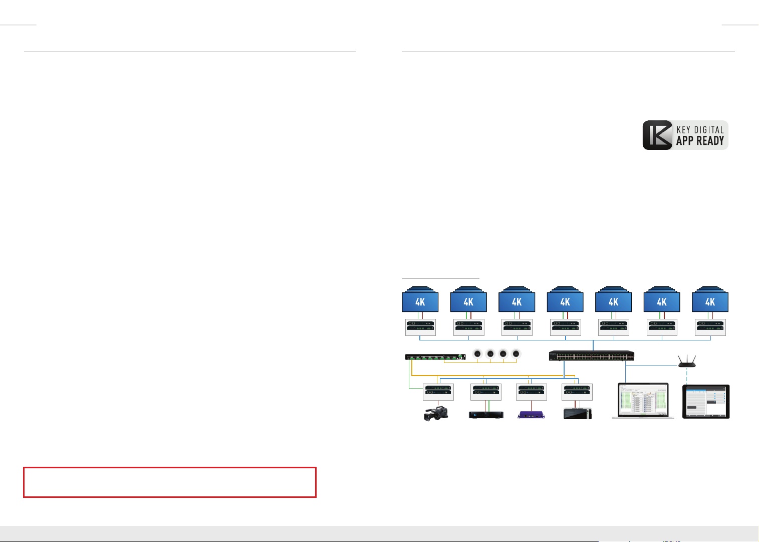
Introduction
Enterprise AV™ Over IP Solutions - Key Digital’s Enterprise AV™
over IP Encoders and Decoders create expandable HDMI over IP
systems that can be scaled to fit any commercial installation:
› Digital Video Matrix
› Digital Video Distribution System
› Digital Video Switcher
› Video Wall Controller
› Digital Video Extender
› KVM Matrix
› Master Controller
Add Encoder units to your system to integrate each video source/input and Decoder units for
each video display/output. The I/O amounts are completely flexible with Enterprise AV with
1024 maximum sources and an unlimited amount of displays.
Digital Video Matrix
RS232
HDMI
KD-IP922DEC
Audio Amplifier
De-Embedded Audio
RS232
HDMI
Camera
x6
RS232
HDMI
KD-IP922DEC
KD-IP922ENCKD-IP922ENC
x6
HDMI IR/RS232
RS232
HDMI
KD-IP922DEC
KD-IP922ENC
HDMI
x6
RS232
KD-IP922DEC
TCP/IP
HDMI
x6
Managed Gigabit Switch
KD-IP922ENC
USB
HDMI
PCCable/Satellite Digital Signage
RS232
KD-IP922DEC
TCP/IP
HDMI
x6
TCP/IP
System Setup
Enterprise AV Utility
RS232
HDMI
KD-IP922DEC
x6
WiFi
1
DirecTV 1
IP: 192.168.202.20
DirecTV 3
3
IP: 192.168.202.22
DirecTV 5
5
IP: 192.168.202.21
DirecTV 7
7
IP: 192.168.202.21
9
DirecTV 9
IP: 192.168.202.20
11
DirecTV 11
IP: 192.168.202.22
13
Menu 2
IP: 192.168.202.21
15
Cable 2
IP: 192.168.202.21
RS232
KD-IP922DEC
WiFi Router
System Control
Network Switcher 8x16
Shift Shift Assign to AllPass-thru
2
1
DirecTV 2
East 1
IP: 192.168.202.21
IP: 192.168.202.20
DirecTV 4
4
3
East 2
IP: 192.168.202.21
IP: 192.168.202.20
6
DirecTV 6
5
East 3
IP: 192.168.202.21
IP: 192.168.202.20
8
7
DirecTV 8
East 4
IP: 192.168.202.21
IP: 192.168.202.20
10
DirecTV 10
IP: 192.168.202.21
12
Menu 1
IP: 192.168.202.21
14
Cable 1
IP: 192.168.202.21
16
Cable 3
IP: 192.168.202.21
Main RescanSwitchers Presets Detailed
Key Digital® App
HDMI
x6
DISPLAYSSOURCES
53
2
West 1
IP: 192.168.202.21
53
West 2
4
IP: 192.168.202.21
53
6
West 3
IP: 192.168.202.21
211
8
West 4
IP: 192.168.202.21
Always follow the instructions provided in this Operating Manual.
Please check the Key Digital Website for the most up-to-date Manual.
© 2017 Key Digital, Inc. All rights reserved.
Page 3
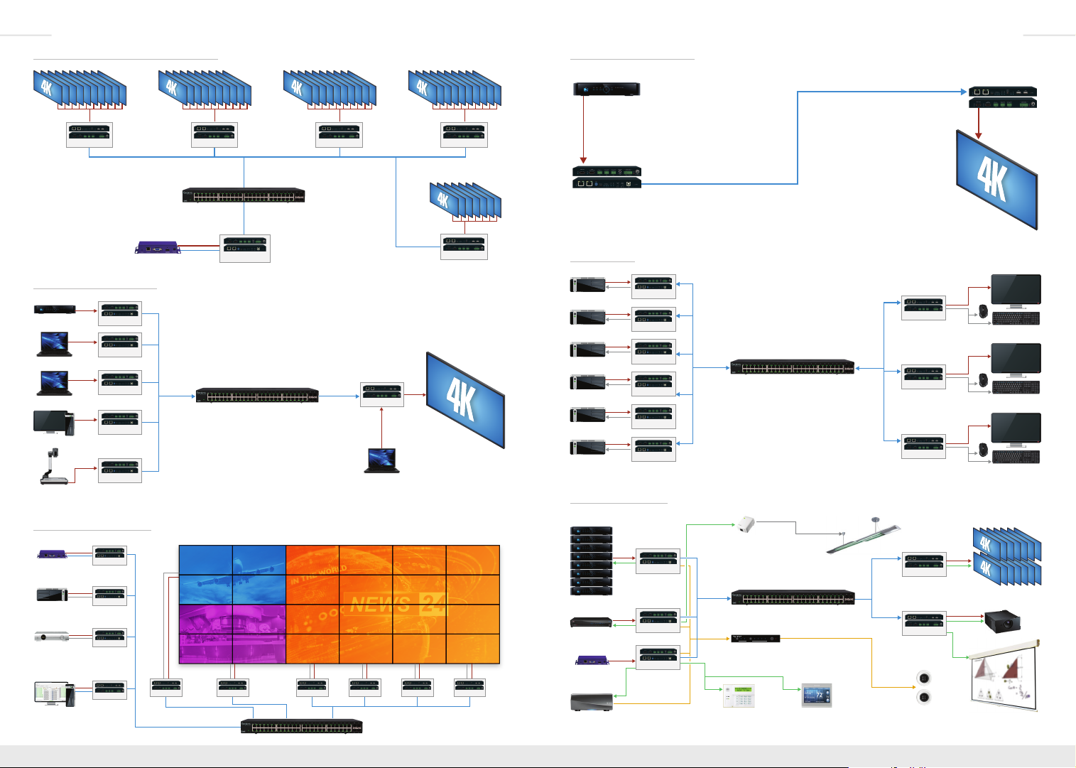
2 3
Digital Signage
Managed Gigabit Switch
Motorized Screen
Digital Video Distribution System
HDMI
KD-IP922DEC
x10
HDMI
KD-IP922DEC
Managed Gigabit Switch
HDMI
TCP/IP
Digital Video Switcher
Laptop 1
Laptop 2
Document
Camera
HDMI
HDMI
HDMI
HDMI
HDMI
KD-IP922ENC
KD-IP922ENC
KD-IP922ENC
KD-IP922ENC
KD-IP922ENC
TCP/IP TCP/IP
Cable/Satellite
Dedicated PC
Video Wall Controller
HDMI
TCP/IP
HDMI
USB
HDMI
IR/RS232
HDMI
TCP/IP
KD-IP922ENC
KD-IP922ENC
KD-IP922ENC
KD-IP922DEC
TCP/IP
RS232
KD-IP922DEC
HDMI
x4
Digital Signage
Signage PC 1
Cable/Satellite
Enterprise AV Utility
Operator Station
(PC)
x10
TCP/IP
KD-IP922ENC
Managed Gigabit Switch
HDMI
RS232
KD-IP922DEC
x4
RS232
KD-IP922DEC
HDMI
KD-IP922DEC
HDMI
x4
TCP/IP
x10
TCP/IP
KD-IP922DEC
Laptop 3 (Local)
HDMI
RS232
KD-IP922DEC
Digital Video Extender
HDMI
HDMI
HDMI
KD-IP922DEC
TCP/IP
HDMI
KD-IP922DEC
Cable/Satellite
TCP/IP
x10
HDMI HDMI
Up to 330 ft / 100 m @ 4K
KD-IP922ENC
x7
KVM Matrix
HDMI
USB
PC 1
HDMI
USB
PC 2
HDMI
USB
PC 3
HDMI
USB
PC 4
HDMI
USB
PC 5
HDMI
USB
PC 6
KD-IP922ENC
KD-IP922ENC
KD-IP922ENC
KD-IP922ENC
KD-IP922ENC
KD-IP922ENC
TCP/IP
KD-IP922DEC
Managed Gigabit Switch
KD-IP922DEC
KD-IP922DEC
KD-IP922DEC
HDMI
USB
Operator Station 1
HDMI
USB
Operator Station 2
HDMI
USB
Operator Station 3
Master Controller
Satellite (8)
HDMI
IR
KD-IP922ENC
x8
Cable
HDMI
KD-IP922ENC
IR
Digital Signage
HDMI
RS232
KD-IP922DEC
x4
x4
RS232
KD-IP922DEC
HDMI
Music Streamer
x4
Audio
HDMI
KD-IP922ENC
IR
RS232
Lighting
Audio
Input Control
Managed Gigabit Switch
KD-AMP220
KD-AMP220
1
2
Mic
Line BassL/R PCM
Treble
Mute
Vol
DSP + Amplifier
TCP/IP
RS232 RS232
Dimmable Lights
TCP/IP
KD-IP922DEC
KD-IP922DEC
Speakers
HDMI
IR/RS232
x14
HDMI
IR/RS232
5V Voltage
Trigger
Displays (14)
Projector
Page 4
4 5
Network Switcher 8x24 KD-HD8x8Lite
Network Switcher 8x16 Network Switcher
Main RescanSwitchers
Presets
Detailed
Switchers
SOURCES
ShiftPass-thru
1
DirecTV 1
3
DirecTV 2
5
DirecTV 3
7
DirecTV 4
9
DirecTV 5
11
Menu
13
Promo
15
Cable 1
2
DirecTV 1
4
DirecTV 2
6
DirecTV 3
8
DirecTV 4
10
DirecTV 5
12
Menu
14
Promo
16
Cable 1
DISPLAYS
Assign to All
1
East 1
3
West 1
5
North 1
7
Bar 1
2
East 2
4
West 2
6
North 2
8
Bar 2
3 4
3 4
11 8
1 2
Network Switcher 8x16
Main Switchers Presets Detailed Help
Switchers
Product Catalog
The Experts in Digital Video Technology and Solutions
™
www.keydigital.com
Key Features
› Enterprise AV Over IP: Utilizes a managed gigabit network switch to enable video
distribution, matrix switching, and extension.
› Video Wall Processing: Encoder + Decoder systems create video walls with up
to 10V and 10H monitors
› HDCP 2.2: Compliancy up to HDCP 2.2 and backward compliant
› 4K/Ultra HD Resolution: Support for 4096x2160 or 3840x2160 24/25/30Hz at 4:4:4/8 Bit
or 60Hz at 4:2:0/8 Bit
› Signal Extension: Up to 330 ft. / 100 m @ 4K 24/25/30(4:4:4)/60(4:2:0) into network switch
or point-to-point
› Power over Ethernet: Does not require power supply when integrated with compatible PoE
network switch
› Dual LAN: Enable system expansion beyond a 48 port system
› Redundant Power Supply: Added reliability for non-PoE integration
› Audio De-Embedding: Audio from the HDMI input is de-embedded through Analog L/R
Balanced/Unbalanced phoenix terminal to enable external audio connectivity with audio
distribution systems and amplifiers
› Audio DSP: Volume, muting, 3-band EQ, and lip-sync delay controllable on
audio de-embed port
› HDMI Pass-Through: Enables connection to local monitor or additional devices up to 75 ft.
®
› HDMI
and HDCP Licensing: Fully licensed and compatible with HDCP 2.2 and HDMI
latest technology such as 4K/UHD 4:2:0/8bit at 60f/s
› Control: 3 multi-function ports controllable via KeyCode open API, as Compass Control
master controller, or as control extension via IP
› USB 2.0: Supports synchronous and isochronous connections
› EDID Control: Internal library features 15 default EDID configurations and native EDID data
from Output/Display devices connected to Decoder
› Hot Plug Detection Control: Enables integrator to choose if active signal voltage is forced
to connected input devices
› Full Buffer System
™
: Manages TMDS re-clocking / signal re-generation, HDCP
authentication with source & display, EDID Control handshake, and Hot Plug control
› IR Sensor: Sensor powering via +5V IR In port collects line-of-sight IR from remote(s)
without external IR connecting block
› Up/Down IR: Two channels of IR enable control to/from devices connected to Encoder and
Decoder units
› RS-232: Bi-Directional control to/from Encoder and Decoder unit on Phoenix connector
› RS-232/TCP-IP Control Mode: Provides control of unit as well as connectivity status
› Lossless compressed digital audio: Support for Dolby
®
Atmos
, and DTS-HD Master Audio
®
TrueHD, Dolby® Digital Plus, Dolby
™
› I2C Communication: EDID and HDCP authentication to Display and Source
› Control System Support: Controllable by all IR, RS-232 & TCP/IP supported control
systems via open API: Compass Control
®
URC
, Leviton® etc.
› Key Digital
®
App Ready:
Can be controlled over TCP/IP via Key Digital® iOS App
®
, AMX®, Control4®, Crestron®, KNX®, RTI®, Savant,
› Data Stream Bandwidth: < 900Mbps
› Latency: <40ms at 4K. Less at lower resolution.
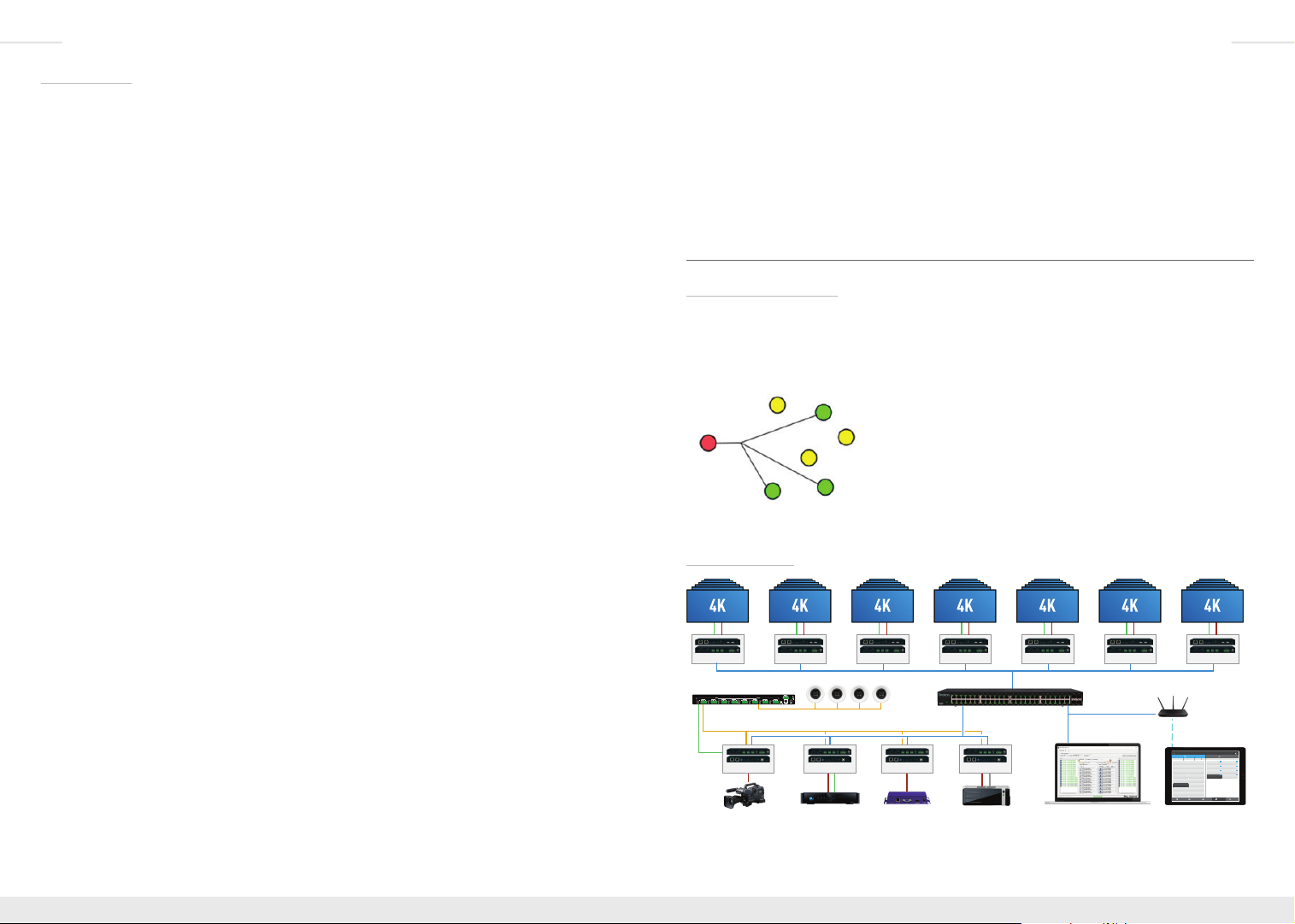
Considerations and Preparations
Technology Overview:
Key Digital’s Enterprise AV over IP products enable distribution, switching, and extension
of HD Video and other media using managed network switches as the central hub of the
system.
Enterprise AV utilizes multicasting technology to broadcast (encode) the source media (ie HD
video, audio, IR and RS-232 control, USB) to connected
network devices. Decoders receive the desired source by
setting a Group ID that corresponds with the ID of the desired
encoder.
The network switch must support IGMP v2 (Internet Grouping
Management Protocol) and 8K Jumbo Frame in order to
®
undesired decoder or interrupting other non-Enterprise AV network devices.
System Design:
RS232
HDMI
KD-IP922DEC
Audio Amplifier
De-Embedded Audio
RS232
HDMI
Camera
RS232
HDMI
x6
KD-IP922DEC
KD-IP922ENCKD-IP922ENC
HDMI IR/RS232
Enterprise AV is different from traditional fixed-chassis video matrixing systems (ie 4x4, 8x8,
16x16). For each video source/input, add an Encoder unit. For each video display/output,
prevent a broadcasted signal from being received at an
RS232
HDMI
x6
KD-IP922DEC
KD-IP922ENC
HDMI
RS232
HDMI
x6
KD-IP922DEC
RS232
HDMI
x6
KD-IP922DEC
x6
TCP/IP
TCP/IP
Managed Gigabit Switch
TCP/IP
System Setup
KD-IP922ENC
USB
HDMI
PCCable/Satellite Digital Signage
Enterprise AV Utility
RS232
HDMI
KD-IP922DEC
x6
1
DirecTV 1
IP: 192.168.202.20
DirecTV 3
3
IP: 192.168.202.22
DirecTV 5
5
IP: 192.168.202.21
DirecTV 7
7
IP: 192.168.202.21
9
DirecTV 9
IP: 192.168.202.20
11
DirecTV 11
IP: 192.168.202.22
13
Menu 2
IP: 192.168.202.21
15
Cable 2
IP: 192.168.202.21
RS232
KD-IP922DEC
WiFi Router
WiFi
System Control
Network Switcher 8x16
Shift Shift Assign to AllPass-thru
2
1
DirecTV 2
East 1
IP: 192.168.202.21
IP: 192.168.202.20
DirecTV 4
4
3
East 2
IP: 192.168.202.21
IP: 192.168.202.20
6
DirecTV 6
5
East 3
IP: 192.168.202.21
IP: 192.168.202.20
8
7
DirecTV 8
East 4
IP: 192.168.202.21
IP: 192.168.202.20
10
DirecTV 10
IP: 192.168.202.21
12
Menu 1
IP: 192.168.202.21
14
Cable 1
IP: 192.168.202.21
16
Cable 3
IP: 192.168.202.21
Main RescanSwitchers Presets Detailed
Key Digital® App
HDMI
x6
DISPLAYSSOURCES
53
2
West 1
IP: 192.168.202.21
53
West 2
4
IP: 192.168.202.21
53
6
West 3
IP: 192.168.202.21
211
8
West 4
IP: 192.168.202.21
Page 5
6 7
add a Decoder unit. Up to 1024 encoders can be integrated with an unlimited amount of
displays.
For example, if your system requires 4 video sources to be distributed to 42 displays, you
may build a system using (4) KD-IP9222ENC, (42) KD-IP9222DEC, and the appropriate
IGMP network switch.
You must ensure that all units are fully configured before connecting all units to your network
switch. Refer to the Unit and System Setup using KD Wizard Utility section for more
information.
Product Compatibility:
Key Digital Enterprise AV product family consists of many different models. Not all models
are compatible together.
Model Function Max Video
Rack Mount Note
Res
KD-IP922ENC Encoder (Tx) UHD/4K KD-RKSMS12 Not compatible
KD-IP922DEC Decoder (Rx)
with KD-IP1080/
KD-IP120 systems
KD-IP1080Tx Encoder (Tx) 1080p KD-RK120PLT Not compatible
KD-IP1080Rx Decoder (Rx)
KD-IP120Tx Encoder (Tx) 1080p KD-RK120PLT
with KD-IP922
systems
KD-IP120Rx Encoder (Tx)
KD-IP120POETx Decoder (Rx)
KD-IP120POERx Decoder (Rx)
KD-IP922ENC + KD-IP922DEC systems are not compatible with
KD-IP1080Tx + KD-IP1080Rx systems
Choosing the right network equipment:
Enterprise AV requires a Full Gigabit network switch with IGMP v2 (Internet Group
Management Protocol), and 8K Jumbo Frame support.
An up to date list of verified network switches is available on all Enterprise AV product pages
the Key Digital web page:
http://www.keydigital.com/Items.asp?ItemCode=KDIP922ENC&Company=KEY
Choosing the right control interface for Enterprise AV
Enterprise AV has a variety of control options, ensuring that the right interface is presented to
the end-user.
PC software
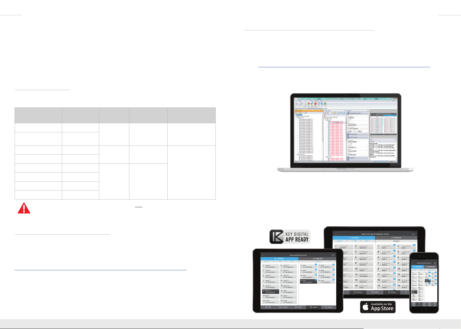
» The KD Wizard software is downloaded from Enterprise AV product pages:
http://www.keydigital.com/Items.asp?ItemCode=KDIP922ENC&Company=KEY
» The software can be used for control and configure Enterprise AV systems
» Screen layout presets can be called or customized to provide a user-friendly interface
that does not give access to system configuration options.
Key Digital App
» The Key Digital app for iOS devices is downloaded from Apple’s App Store
» The Key Digital app provides video switching control, preset creation, displays the
friendly names defined in system setup, and even has demo systems for a test drive.
» The Key Digital app offers control of other Key Digital App Ready devices
» Once launched, the Key Digital app auto-scans to find the Enterprise AV systems on
the local area network
Page 6
8 9
Compass Control® Pro
» The most modern professional control system in the market and the native choice for
controlling Enterprise AV systems
» In addition to Enterprise AV, control audio, video, automation, climate, lighting, shade,
security devices and more within a single app.
» Custom naming of inputs and outputs and status-indicating graphical element provide
a rich user environment
» Drag and drop modular or fully custom GUI programming
» iOS and Android controllers communicate with Key Digital MC gateway via IP for
control of Enterprise AV system. Email tech@keydigital.com for model information on
the gateway
Third-Party Control Systems
» Enterprise AV is fully controllable by RS-232 supported control systems with the use of
a Key Digital control gateway. Email tech@keydigital.com for model information on the
gateway
» Enterprise AV systems use the same switching command as all Key Digital matrix
switches:
» SPOxxSIyy
There are many other methods to control your Enterprise AV system. See the TCP/IP, RS232, and IR Control section for more information.
Connections, LEDs, and Controls
IMPORTANT: Please ensure that each unit has been configured properly
one-at-a-time before connecting multiple units to your network switch.
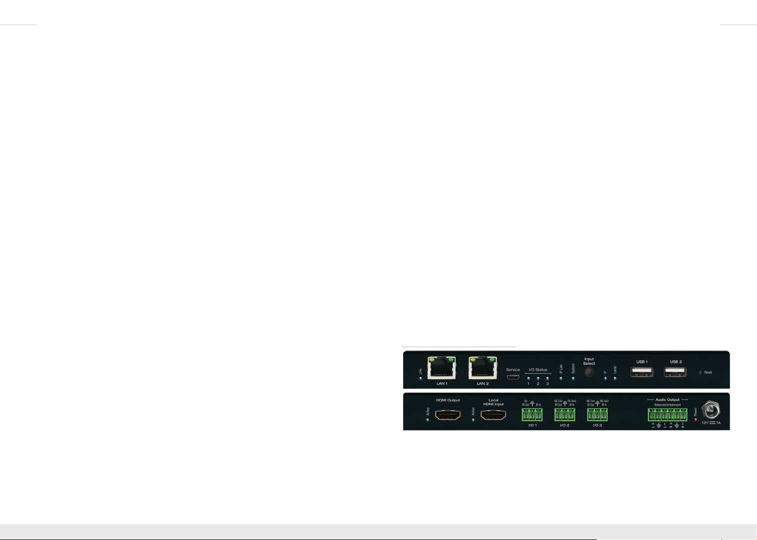
KD-IP922ENC Encoder Unit:
HDMI Input
» Used to connect video source
» Compatible with latest HDMI technologies and resolutions up to 4096x2160 or
3840x2160 24/25/30Hz at 4:4:4/8 Bit or 60Hz at 4:2:0/8 Bit with HDR10
» Supports audio formats up to Dolby® TrueHD, Dolby® Digital Plus, Dolby Atmos®,
and DTS-HD Master Audio™
» Supports HDCP2.2
» LED light illuminated when active HDMI signal link (TMDS) from source is present
HDMI Pass-through
» Used to connect local video monitor, audio systems, etc
» Same supported video and audio formats as HDMI Input connection
» Audio corresponds with current Audio Select source (see External Audio Input below)
» LED light illuminated when active voltage link (HPD) from connected display/output
device is present
Multifunction I/O’s
» Supports four usage modes:
» Control gateway for Enterprise AV Over IP system
» Compass Control Master Controller
» Third-party control via KeyCode Open API
» Control extension via IP
» Configurable as IR sensor, IR input, IR emitter, RS-232, voltage trigger, or voltage
sensor. Some limitations apply per port. See KeyCode Open API Specification section
for more information
» I/O Status lights blink as voltage passes through the I/O ports
Page 7
10 11
External Audio Input
» Used to integrate external analog audio sources
» 3.5mm stereo connection
» Each Encoder can select either HDMI audio or the external audio input via toggle
switch or TCP/IP or RS-232 commands.
» Audio Select switch determines audio source upon unit boot up. Newly received
commands or toggles of Audio Select switch will override current setting
» It is not possible to input both (HDMI + External) audio connections to the Enterprise
AV system
Audio Output
» Used to integrate with peripheral amplifiers and audio distribution systems
» Balanced/Unbalanced 6-pin phoenix terminal
» Features variable volume, muting, bass, mid, treble, and lip-sync level adjust
controllable via TCP/IP or RS-232 command strings
Power
» Redundant power connection for backup in case PoE network switch is not used or
PoE port fails
» 12V/1A (12W) screw-type power supply included
» PoE supported on either LAN port
» OK to connect external power supply plus PoE
LAN Ports
» Used to connect with Network Switch (WiFi not supported) and peripheral devices
needing network connectivity and/or TCP/IP control
» Default IP Address = 192.168.1.100
» May be used with Key Digital Wizard software for unit configuration
» Supports 10/100BaseT up to 100Mbps
» Act as an unmanaged network switch
» Support IGMP with connection IGMP supported network switch
» Respective LED blinks during active network communication
» See Key Digital’s Verified Network Switch document for list of network switches
verified to support Enterprise AV HD Over IP systems
EDID Control Rotary
» Used to select the desired EDID handshake provided to the connected video source
» See EDID and Hot Plug Detection Control section for more information
» Service Micro USB
» Used as primary unit configuration method and for firmware updates.
» Not used for USB data or KVM
IP LED
» Indicates healthy audio/video system status
» Encoder: At least one Decoder partner is viewing signal
» Steady blink during boot up
System LED
» Indicates healthy control system status
» Steady blink during bootloader mode and firmware updates
Forced HPD Switch
» Used to activate voltage from the HDMI input connection regardless of a connected
sync device.
» See EDID and Hot Plug Detection Control section for more information
USB-B
» Used to connect USB Host / Computer
» Not used for connecting USB endpoints (ie keyboard, mouse)
» USB input/output relationship automatically follows video input/output relationship
Reset Pin
» Press and hold for 5 seconds to reset unit to factory default settings, indicated by blink
System LED
» IP Address = 192.168.1.100
» Selected audio source = Corresponds with Audio Select switch
» Group ID = 0000
» Control mode = Control gateway for Enterprise AV Over IP system
KD-IP922DEC Decoder Unit:
HDMI Output
» Used to connect video display
» LED light illuminated when active voltage from display (HPD) is present
» Local HDMI Input
» Used to connect video source for local presentation, etc
» Same supported video and audio formats as KD-IP922ENC HDMI Input connection
Page 8

12 13
» Selectable via Input Select button or via TCP/IP or RS-232 command
» LED light illuminated when active HDMI signal link (TMDS) from source is present
Audio Output
» Variable settings are independent of KD-IP922ENC
» Features variable volume, muting, bass, mid, treble, and lip-sync level adjust
controllable via TCP/IP or RS-232 command strings
LAN Ports
» Default IP Address = 192.168.2.100
IP LED
» Indicates healthy audio/video system status
» Decoder: Successful connection with selected Encoder
» Steady blink during boot up
System LED
» Indicates healthy control system status
» Steady blink during bootloader mode and firmware updates
USB-A Ports
» Used for connecting USB endpoints (ie keyboard, mouse)
» Not used to connect USB Host / Computer
» Supports connectivity to USB hubs but may not exceed 15 endpoint devices
» USB input/output relationship automatically follows video input/output relationship
Reset Pin
» Press and hold for 10 seconds to reset unit to factory default settings:
» IP Address = 192.168.2.100
» Selected video input source = Must be established
Rack Mounting KD-IP922
Key Digital KD-SMS16 is a universal rack shelf that can holds up to 16 KD-IP922 units
utilizing the side mounting screws.
KD-SMS16 supports any Key Digital unit with side mounting screw spacing of 2.912”,
2.582”, or 2.252”.
Page 9

14 15
EDID and Hot Plug Detection Control
EDID Control
EDID authentication is provided from the Encoder units to the connected input/source device.
The EDID file (AKA handshake) is selected using the EDID Control rotary and provides a list
of compatible video and audio formats as well as digital data informed the video source what
is should output. Most sources will comply with a new EDID file without a power-cycle, but
each source may behave differently.
Default EDID Control Table, selected via EDID Control rotary
Position EDID Description EDID Control Rotary
0
1
2
3
4
5
6
7
8
9
A
B
C
D
E
F
Copy EDID from CAT5e/6 Output
1080i, 2CH AUDIO
1080i, DOLBY/DTS 5.1
1080i, HD AUDIO
1080p, 2CH AUDIO
1080p, DOLBY/DTS 5.1
1080p, HD AUDIO
4Kx2K@30, 2CH AUDIO
4Kx2K@30, DOLBY/DTS 5.1
4Kx2K@30, HD AUDIO
4Kx2K@60, 2CH AUDIO
4Kx2K@60, DOLBY/DTS 5.1
4Kx2K@60, HD AUDIO
1280x720p@60 DVI (no audio)
1920x1080@30 DVI (no audio)
3840x2160p@30 DVI (no audio)
Dual Network Switch Systems
You may utilize the dual LAN ports of KD-IP922ENC units to create an expanded system
using two network switches.
This presents a huge cost-savings as compared to systems requiring expensive custom and
card-slot based network switches.
To build an expanded system, connect each KD-IP922ENC LAN port to each network
switches.
There is no need to use the link ports on the network switch. The KD-IP922ENC will serve as
the network bridge between the two switches.
Remember that each encoder unit will occupy 2 total ports on your network switches. The
formula for calculating your possible Encoders and Decoders is:
(Encoders*2) + Decoders = Net Switch Ports
Example:
4 Encoders would allow for up to 88 Decoders if using two 48 port network switches.
(4*2) + 88 = 96
Forced Hot Plug Detection
Hot Plug Detection (HPD) may be forced on the Encoder unit in order to provide connected
devices with necessary voltage to inform the device that a partner (ie display) is connected
and active. If the Forced HPD switch is set to OFF, HPD signals from the output to the input
device will pass as normal. In cases of many layers of connectivity, HPD may be lost leading
to no signal at the display. In those cases, fix the switch to Forced HPD ON.
Page 10

16 17
Other common configurations that can be achieved due to the dual LAN port feature include:
› 8 video sources may have up to 80 displays/outputs if using two 48 port network switches
» (8*2) + 80 = 96
› 16 video sources may have up to 64 displays/outputs if using two 48 port network switches
» (16*2) + 64 = 96
› 24 video sources may have up to 48 displays/outputs if using two 48 port network switches
» (24*2) + 48 = 96
› 32 video sources may have up to 32 displays/outputs if using two 48 port network switches
» (32*2) + 32 = 96
Larger systems are possible with Enterprise AV using 10G and 100G SFP network switches.
Unit and System Setup using KD-Wizard Software
› IMPORTANT:
Digital’s Verified Network Switch document. Document is found on the KD-IP922 product
pages: http://www.keydigital.com/Items.asp?ItemCode=KDIP922ENC&Company=KEY
› Organize and label all units before configuring
1. Download, install, and open Key Digital® Wizard software
2. Connect USB from PC to Encoder #1
3. Press USB Device to begin scan for connected unit
Configure units after properly configuring your network switch according to Key
4. Properties Window
» a) FW Version and Release Date text will be RED if a newer firmware is available
» b) Update firmware by expanding Firmware Update workspace and select Update
Firmware button
» c) Firmware Update dialog popup will show progress. Close dialog popup after
completion.
Note: KD-IP922ENC and KD-IP922DEC feature two firmware types and two buttons
for updating firmware. Be sure to update both firmware files
1.0.8
» d) Set desired Device name with up to 16 characters (ie “DirecTV 1”, “Conf Projector”)
» i) Do not use special characters such as !, @, $, ?
» e) Set desired System Group ID according to desired Input (encoder) or Output
(decoder) number assignment for unit within virtual matrix system
Page 11

18 19
» g) After all property updates are entered, press Update button in Unit Information
workspace
5. Repeat for each unit
Note: For advanced configuration of features such as audio, control, and video wall
please visit product pages for the latest guides:
http://www.keydigital.com/Items.asp?ItemCode=KDIP922ENC&Company=KEY
» f) Enter Network Settings workspace to set desired IP settings
» i) IP Address is static IP assigned to unit
» ii) Gateway is IP address of router
6. Virtual Matrix System Configuration
» a) Connect all units to network switch via LAN port
» b) Hardwire PC computer to the Enterprise AV network and turn off WiFi antenna
» c) Press Network Scan
» d) In Network Devices window, all detected Encoders and Decoders will appear
Page 12

20 21
» ii) Beneath ALL UNITS, each unit will be individually itemized in case a replacement
» e) Choose CONFIGURATION » NEW SWITCHER
» i) Enter desired system file name
» ii) Recommended Starting Group ID is 1 (group ID for first Encoder)
» (1) If multiple switcher systems exist on the same network, they should have
unit is being inserted to existing system and it requires the loaded file.
unique starting Group ID
» iii) Enter desired number of Input and Outputs according to the number of physical
units currently connected
» (1) System file is easily updated if additional units will be added/removed in
All Un its: D emo _23x23
the future
» iv) Press OK to advance to IP System Editor window
» f) Drag scanned devices from Network Devices window to the desired Input / Output
assignment in the IP System Editor window
7. Future software updates will include automatic unit and virtual matrix configuration
» g) After providing all Input/Output assignment, press Link button to finalize assignments
» h) Press Save button
» i) Press Load button to the virtual matrix file
» i) At top of Device list (default) you may select ALL UNITS for automatic loading to
each encoder and decoder, one-by-one.
» (1) The process is long, but requires only one button press for entire system.
Page 13

22 23
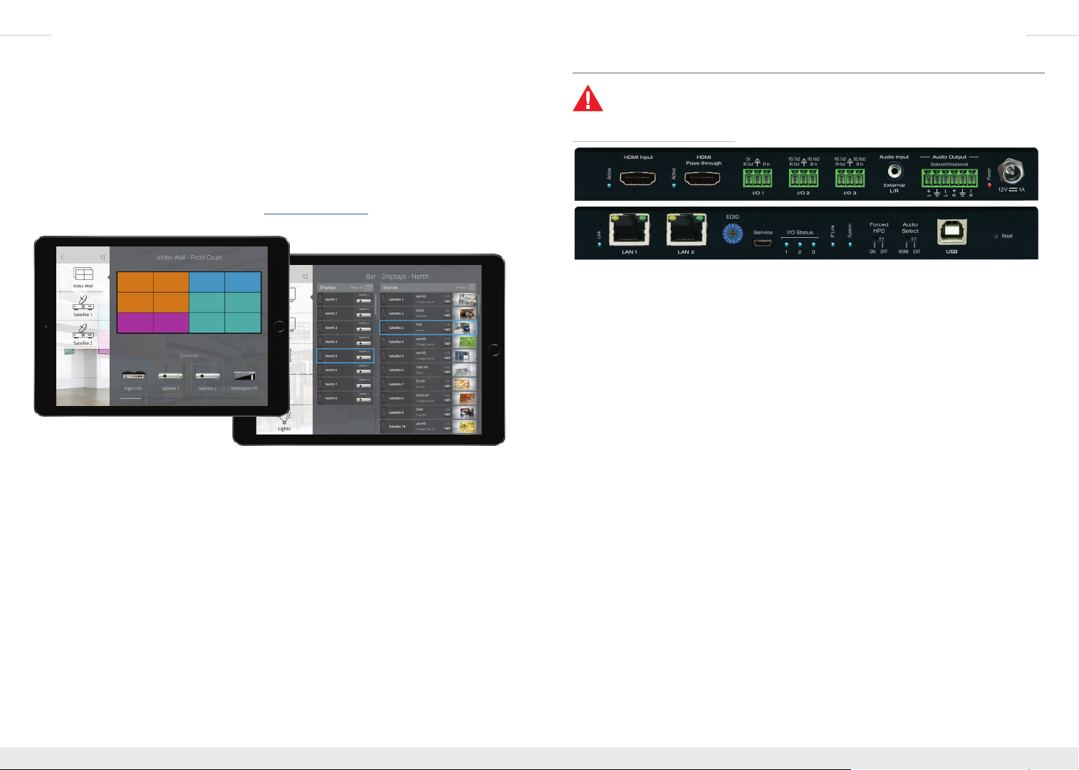
Video Wall Processing
KD-IP922DEC decoders may be used to build video walls up to 10 displays wide and 10
displays high (10x10). A KD-IP922DEC unit is needed at each display.
› Configuring each Decoder’s Video Wall settings is achieved via TCP/IP, RS-232, or using the
KD-Wizard software. Video wall settings will remain if Video Wall mode is toggled.
› Video walls are created by specifying the following:
» Video Wall ID
» Number of vertical displays
» Number of horizontal displays
» Position of the display within the configuration
» Position begins at 1
» Position moves from left to right, top to bottom. Just like reading an English
language book
› KD-IP922 systems support advanced video wall assignment options to enable building of
advanced GUI control layouts:
» Video Walls must be assigned a unique ID number
» This is helpful for controlling specific video walls when multiple walls are installed
on site
» Decoders may be given a Main and Sub video wall assignment
» This is helpful for breaking up a large video wall into smaller video wall segments
» All displays within a main video wall must be assigned the same Main Group ID
Example: 4Vx6H main video wall containing two 2Vx2H and one 4Vx4H sub video walls
› For the Main Wall:
» Video Wall ID = 01
» Number of horizontal displays = 6
» Number of vertical displays = 4
» Position of each display = 001 ~ 024
› For the sub video walls within the main video wall:
» Number of horizontal displays = 2
» Number of vertical displays = 2
» Position of each display = 001 ~ 004
»
A. Commands to configuring video wall
» With Video Wall mode enabled, each decoder is informed of the number of horizontal
and vertical displays in the overall video wall, the ID assignment of the video wall, and
the decoder’s position within the video wall
B. Commands for bezel adjustment
» KD-IP922DEC can perform automatic bezel adjustment based on the each display’s
overall dimensions (including bezel) and screen dimensions
C. Commands for fine tuning
» If needed, KD-IP922DEC can also move the image up, down left or right
» Horizontal or Vertical Zoom may also be applied
D. Commands for screen rotation
» Images may be rotated 0°, 180°, and 270°
Page 14

24 25
TCP/IP, RS-232, and IR Control
KD-IP922 systems may be controlled via TCP/IP, RS-232, or IR:
» Each KD-IP922 unit may receive system commands (ie. matrix switching)
» Each KD-IP922 unit may receive unit-specific commands (ie. audio DSP and video wall
commands)
» Any unit-specific command received is forwarded to the appropriate unit
As with other Key Digital products, a full
the Enterprise AV system) and
Status
RS-232 connection protocol:
» Baud Rate = 57600 bits per second
» Data Bits = 8
» Stop Bits = 1
» Parity = None
» Flow Control = None
» Carriage Return: Required
» Line Feed: Required
Control notes:
» Commands are not case-sensitive
» Spaces are shown for clarity; commands should NOT have any spaces
» Carriage return and line feed is required at the end of each string
» If a new command is received, a confirmation is transmitted from the unit
Help Command (H) returns entire API in readable format:
-------------------------------------------------------------------------
-- Key Digital Systems HELP --
-------------------------------------------------------------------------
-- KD-IP922ENC F/W Version : BV1.00, MV1.00, AV1.00 --
-- --
-- PN : Power On --
-- PF : Power O --
-- H : Help --
-- STA : Show Global System Status --
-- STPIxx : Show Video Input xx Status --
-- STPIxxxx : Show Video Input xxxx Status --
-- STPOxx : Show Video Output xx Status --
-- STPOxxxx : Show Video Output xxxx Status --
-- --
-- Video Output Setup Command ( xxxx=[0~1024], yyyy=[1~1024] ) --
-- SPO xxxx SI yyyy : Set Output xxxx to Video Input yyyy --
-- SPO xx yy : Set Output xx to Video Input yy --
-- xxByy. : Set Output xx to Video Input yy --
Help
(set/listing of all possible commands to send
(get/feedback of current system status) is possible.
-- Bxxyy : Set Output xx to Video Input yy --
-- SPO xxxx SIU : Set Output xxxx Video Input Up --
-- SPO xxxx SID : Set Output xxxx Video Input Down --
-- SPOASI yyyy : Set All Outputs to Video Input yyyy --
-- SPO A yy : Set All Outputs to Video Input yyyy --
-- yyAll. : Set All Outputs to Video Input yy --
-- SPOASIU : Set All Outputs to Video Input Up --
-- SPOASID : Set All Outputs to Video Input Down --
-- SPOAPT : Set All Outputs to Pass Through --
-- SPO xxxx VM E/D : Set Output xxxx Video Mute Enabled/Disabled --
-- SPO xxxx ON/OFF : Set Output xxxx ON/OFF --
-- SPO xxxx DBG ON/OFF : Set Output xxxx Debug Mode ON/OFF --
-- SPOA VM E/D : Set All Outputs Video Mute Enabled/Disabled --
-- SPOA ON/OFF : Set All Outputs ON/OFF --
-- SPOA DBG ON/OFF : Set All Outputs Debug Mode ON/OFF --
-- --
-- Video Wall Setup Command xxxx=[0~1024], yyyy=[0~9999] ) --
-- SPO xxxx VWE/D : Set Video Wall E=Enable/D=Disable --
-- SPO xxxx VID yy : Set Group ID of Video Wall --
-- SPO xxxx MWH yy : Set Number of Horizontal Main Display y=[1~10] --
-- SPO xxxx MWV yy : Set Number of Vertical Main Display y=[1~10] --
-- SPO xxxx MWP yyy : set Position of Main Display yyy=[1~100] --
-- SPO xxxx SWH yy : Set Number of Horizontal Sub Display y=[1~10] --
-- SPO xxxx SWV yy : Set Number of Vertical Sub Display y=[1~10] --
-- SPO xxxx SWP yyy : set Position of Sub Display yyy=[1~100] --
-- SPO xxxx BWL yyyy : Set Bezel Width(mm) by yyyy=[1~9999] --
-- SPO xxxx BHL yyyy : Set Bezel Height(mm) by yyyy=[1~9999] --
-- SPO xxxx SWL yyyy : Set Screen Width(mm) by yyyy=[1~9999] --
-- SPO xxxx SHL yyyy : Set Screen Height(mm) by yyyy=[1~9999] --
-- SPO xxxx MSL yyy : Move Screen Position to Left yyy=[0~480] --
-- SPO xxxx MSR yyy : Move Screen Position to Right yyy=[0~480] --
-- SPO xxxx MSU yyy : Move Screen Position to Up yyy x=[0~270] --
-- SPO xxxx MSD yyy : Move Screen Position to Down yyy=[0~270] --
-- SPO xxxx SUH yyyy : Scale Up Horizontal Screen by yyyy=[0~9999] --
-- SPO xxxx SUV yyyy : Scale Up Verical Screen by yyyy=[0~9999] --
-- SPO xxxx SRR y : Set Screen Rotation by y=[0:0’, 1:180’, 2:270’] --
-- --
-- IP922ENC Audio Setup Command ( xxxx=[0~1024,A] A=All ) --
-- SPE xxxx AS y : Set Input xxxx Audio Source to y [1=HDMI, 2=EXT.] --
-- SPE xxxx AV yy : Set Input xxxx Audio Volume to yy=[00-99],U,D --
-- SPE xxxx AB yy : Set Input xxxx Audio Balance to yy=[00-40],U,D --
-- SPE xxxx AL yy : Set Input xxxx Audio Bass to yy=[00-24],U,D --
-- SPE xxxx AM yy : Set Input xxxx Audio Middle to yy=[00-24],U,D --
-- SPE xxxx AH yy : Set Input xxxx Audio Treble to yy=[00-24],U,D --
-- SPE xxxx AD yy : Set Input xxxx Audio Delay to yy=[00-99],U,D --
-- SPE xxxx A E/D : Set Input xxxx Audio Mute E=Enabled/D=Disabled --
-- --
Page 15

26 27
-- IP922DEC Audio Setup Command ( xxxx=[0~1024,A] A=All ) --
-- SPD xxxx AV yy : Set Output xxxx Audio Volume to yy=[00-99],U,D --
-- SPD xxxx AB yy : Set Output xxxx Audio Balance to yy=[00-40],U,D --
-- SPD xxxx AL yy : Set Output xxxx Audio Bass to yy=[00-24],U,D --
-- SPD xxxx AM yy : Set Output xxxx Audio Middle to yy=[00-24],U,D --
-- SPD xxxx AH yy : Set Output xxxx Audio Treble to yy=[00-24],U,D --
-- SPD xxxx AD yy : Set Output xxxx Audio Delay to yy=[00-99],U,D --
-- SPD xxxx A E/D : Set Output xxxx Audio Mute Enabled/Disabled/Toggle --
-- --
-- IP922DEC Video Setup Command ( xx/xxx/xxxx=[0000~1024,A] A=All ) --
-- SPD xxxx VS y : Set Output xxxx Video Source to y [1=IP, 2=Local] --
-- --
-- Network Setup Command ( xxx=[000-255], zzzz=[0001~9999], y=[1~3] ) --
-- SPCETIPA xxx.xxx.xxx.xxx : Set Host IP Address to xxx.xxx.xxx.xxx --
-- SPCETIPM xxx.xxx.xxx.xxx : Set Net Mask to xxx.xxx.xxx.xxx --
-- SPCETIPR xxx.xxx.xxx.xxx : Set Route IP Address to xxx.xxx.xxx.xxx --
-- SPCETIPP zzzz : Set TCP/IP Port to zzzz --
-- SPCETDCP E/D : Set DHCP E=Enable/D=Disable --
-- SPCETIPB : Apply New Network Cong --
-- SPCETLN1 y : Set LAN Port1 by y [1=1G-BaseT, 2=100BaseT, 3=Auto] --
-- SPCETLN2 y : Set LAN Port2 by y [1=1G-BaseT, 2=100BaseT, 3=Auto] --
-- --
-- Control I/O Port Setup Command ( x=[0~3], y=[0~9], z=[0001-9999] ) --
-- SPB x CM y : Set Control Mode of I/O Port x=[1~3] by y --
-- [1=IP922 Control, 2=Compass Control, 3=Open API, 4=Control Ext.] --
-- SPB x PC y : Set Port Conguration of I/O Port x=[1~3] by y --
[0=None, 1=IR IN, 2=IR OUT, 3=RS232, 4=TRIGGER IN, 5=TRGGER OUT] --
-- SPB 1 IRS y : Set IR Source by y [1=IR Sensor, 2=Serial IR ] --
-- SPB x RSB y : Set RS232 Baud Rate of I/O Port x=[2~3] by y bps --
-- [0=115200, 1=57600, 2=38400, 3=19200, 4=9600, 5=4800]--
-- SPB x RSL y : Set RS232 Data Length of I/O Port x=[2~3] by y=[7~8] --
-- SPB x RSP y : Set RS232 Parity Bit of I/O Port x=[2~3] by y=[0~2] - [0=None, 1=Odd, 2=Even] --
-- SPB x RSS y : Set RS232 Stop Bit of I/O Port x=[2~3] by y=[0~2] --
-- SPB x OSL y : Set Output Level of I/O Port x by y [1=MIN ~ 7=MAX] --
-- SPB x TCP zzzz : Set TCP Port of I/O Port x[0=I/O Port Cfg.] by zzzz--
-- SPB x IGD zzz : Set IR IN/RS232 RxD Group ID of I/O Port x by zzz --
-- SPB x OGD zzz : Set IR OUT/RS232 TxD Group ID of I/O Port x by zzz --
-- --
-- System Control Setup Command ( xx=[0000-1024], y=[1~4], z=[0-4] ) --
-- SPC DN cccccccccccccccc : Set Device Name --
-- SPC SID xxxx : Set System ID xxxx for Multicast,[0000=Unicast] --
-- SPCFB E/D : Set Panel Button E/D (E=Enable,D=Disable) at IP922DEC--
-- SPCDF : Reset to Factory Default All --
-------------------------------------------------------------------------
Status command (STA) returns current state and settings of the unit:
-------------------------------------------------------------------------
-- Key Digital Systems STATUS --
-------------------------------------------------------------------------
-- KD-IP922ENC F/W Version : BV1.00, MV1.00, AV1.00 --
-- --
-- Device Name = IP922ENC0001 , System ID = 0001 --
-- Power = ON, Fanel Button = Enable, Forced HPD = OFF --
-- --
-- Network Setting Status --
-- MAC Address = 60:89:B1:90:00:01 --
-- Host IP Address = 192.168.001.100 --
-- Net Mask = 255.255.000.000 --
-- Router IP Address = 192.168.001.001 --
-- TCP Port = 0023, DHCP = Disable, Link = ON --
-- LAN1 = AUTO, LAN2 = AUTO --
-- --
-- Control I/O Ports Status --
-- Main : TCP = 4580 --
-- I/O1: CM=IP922 , CFG=IR IN ,OSL=7, RS=57600-8-0-1 , IRS=1 --
-- TCP=4581, IGD=0001, OGD = 0002 --
-- I/O2: CM=IP922 , CFG=NONE ,OSL=7, RS=57600-8-0-1 , IRS=2 --
-- TCP=4582, IGD=0003, OGD=0004 --
-- I/O3: CM=IP922 , CFG=RS232 ,OSL=7, RS=57600-8-0-1 , IRS=2 --
-- TCP=4583, IGD=0005, OGD=0006 --
-- --
-- IP922ENC Video/Audio Status --
-- 0001: DN=IP922ENC0001 , MAC=60:89:B1:90:00:01, GID=0001, LINK=ON --
-- IP=192.168.001.101 , VA=HDMI , HPD=ON ,HCP=ON , AUD=2CH PCM --
-- AS=HDMI, AV=99, AB=20, AL=12, AM=12, AH=12, AD=00, MUTE=OFF --
-- 0002: DN=IP922ENC0002 , MAC=60:89:B1:90:00:01, GID=0002, LINK=ON --
-- IP=192.168.001.102 , VA=HDMI , HPD=ON ,HCP=ON , AUD=2CH PCM --
-- AS=HDMI, AV=99, AB=20, AL=12, AM=12, AH=12, AD=00, MUTE=OFF --
-- 0003: DN=IP922ENC0003 , MAC=60:89:B1:90:00:01, GID=0003, LINK=ON --
-- IP=192.168.001.103 , VA=HDMI , HPD=ON ,HCP=ON , AUD=2CH PCM --
-- AS=HDMI, AV=99, AB=20, AL=12, AM=12, AH=12, AD=00, MUTE=OFF --
-- 0004: DN=IP922ENC0004 , MAC=60:89:B1:90:00:01, GID=0004, LINK=ON --
-- IP=192.168.001.104 , VA=HDMI , HPD=ON ,HCP=ON , AUD=2CH PCM --
-- AS=HDMI, AV=99, AB=20, AL=12, AM=12, AH=12, AD=00, MUTE=OFF --
-- --
-- IP922DEC Video/Audio/Video Wall Status --
-- 0001: DN=IP922DEC0001 , MAC=60:89:B1:92:00:01, GID=0001, LINK=ON --
-- IP=192.168.002.101, IN=0001, OUT=ON , HPD=ON ,HCP=ON , DG=ON --
-- AV=99, AB=20, AL=12, AM=12, AH=12, AD=00, MUTE=OFF --
-- VW=OFF, VID=00, MWH=01, MWV=01, MWP=001, SWH=01, SWV=01 --
-- SWP=001, BWL=0001, BHL=0001, SWL=0001, SHL=0001, MSL=000 --
-- MSR=000, MSU=000, MSD=000, SUH=0000, SUV=0000, SRR=0 --
Page 16

28 29
-- 0002: DN=IP922DEC0002 , MAC=60:89:B1:92:00:02, GID=0002, LINK=ON --
-- IP=192.168.002.102, IN=0002, OUT=ON , HPD=ON ,HCP=ON , DG=ON --
-- AV=99, AB=20, AL=12, AM=12, AH=12, AD=00, MUTE=OFF --
-- VW=OFF, VID=00, MWH=01, MWV=01, MWP=001, SWH=01, SWV=01 --
-- SWP=001, BWL=0001, BHL=0001, SWL=0001, SHL=0001, MSL=000 --
-- MSR=000, MSU=000, MSD=000, SUH=0000, SUV=0000, SRR=0 --
-- 0003: DN=IP922DEC0003 , MAC=60:89:B1:92:00:03, GID=0003, LINK=ON --
-- IP=192.168.002.103, IN=0003, OUT=ON , HPD=ON ,HCP=ON , DG=ON --
-- AV=99, AB=20, AL=12, AM=12, AH=12, AD=00, MUTE=OFF --
-- VW=OFF, VID=00, MWH=01, MWV=01, MWP=001, SWH=01, SWV=01 --
-- SWP=001, BWL=0001, BHL=0001, SWL=0001, SHL=0001, MSL=000 --
-- MSR=000, MSU=000, MSD=000, SUH=0000, SUV=0000, SRR=0 --
-- 0004: DN=IP922DEC0004 , MAC=60:89:B1:92:00:04, GID=0004, LINK=ON --
-- IP=192.168.002.104, IN=0004, OUT=ON , HPD=ON ,HCP=ON , DG=ON --
-- AV=99, AB=20, AL=12, AM=12, AH=12, AD=00, MUTE=OFF --
-- VW=OFF, VID=00, MWH=01, MWV=01, MWP=001, SWH=01, SWV=01 --
-- SWP=001, BWL=0001, BHL=0001, SWL=0001, SHL=0001, MSL=000 --
-- MSR=000, MSU=000, MSD=000, SUH=0000, SUV=0000, SRR=0 --
-------------------------------------------------------------------------
IR Control is possible using remote model KD-REMOTEHM88 (sold separately)
Use the numerical keypad for X, Y, and Z values below. X, Y, and Z values may be up to four
button presses.
All unit setup should be completed in the KD Wizard software found on
www.keydigital.com
Command Sequence
Audio Input Setup
Set Analog Input x by y [1=Unbalanced, 2=Balanced] R2, X, Audio Mode, Y
Output Video Setup
Set Output x to Video Input y R1, X, X, X, X, Video Mode, Y, Y, Y, Y
Set Output x Video Input Up R1, X, X, X, X, Video Mode, UP
Set Output x Video Input Down R1, X, X, X, X, Video Mode, DOWN
Set All Outputs to Video Input y R1, Video Mode, Y, Y
Set All Outputs to Video Input Up R1, Video Mode, UP
Set All Outputs to Video Input Down R1, Video Mode, DOWN
Set Analog Input xx by y [1=Unbalanced, 2=Balanced] R2, X, Audio Mode, Y
Set Output x to Video Input y R1, X, Video Mode, Y
Set Output x Video Input Up R1, X, Video Mode, UP
Set Output x Video Input Down R1, X, Video Mode, DOWN
Set All Outputs to Video Input y R1, Video Mode, Y,
Set All Outputs to Video Input Up R1, Video Mode, UP
Set All Outputs to Video Input Down R1, Video Mode, DOWN
Set All Outputs to Pass Through R1, Video Mode, Audio Mode
Set Output x Video Mute Enabled/Disabled R1, X, Video Mode, Mute/Restore
Set Output x ON/OFF R1, X, Video Mode, R2, Restore/Mute
Set Output x Debug Mode ON/OFF R1, X, Video Mode, R3, Restore/Mute
Set All Outputs Video Mute Enabled/Disabled R1, Video Mode, Restore/Mute
Set All Outputs ON/OFF R1, Video Mode, R2, Restore/Mute
Set All Outputs Debug Mode ON/OFF R1, Video Mode, R3, Restore/Mute
Audio Output Setup
Set Analog De-Embed Source to y [1=HDMI, 2=EXT.
AUDIO L/R]
Set Output x Audio Volume to yy yy=[00-99] R1, X, Volume, Y, Y
Set Output x Audio Balance to yy, yy=[00-40],U,D
R2, Audio Mode, Y
Page 17

30 31
Set Output x Audio Volume Up R1, X, Volume, UP
Set Output x Audio Volume Down R1, X, Volume, DOWN
Set Output x Audio Bass Freq. to yy, yy=[00-24],U,D R1, X, Bass, Y, Y
Set Output x Audio Middle Freq. to yy, yy=[00-24],U,D R1, X, Middle, Y, Y
Set Output x Audio Treble Freq. to yy, yy=[00-24],U,D R1, X, Treble, Y, Y
Network Setup
Set Output x Audio Delay to yy yy=[00-99],U,D R1, X, LipSync, Y, Y
Set Output x Audio Mute Enabled/Disabled R1, X, Mute/Restore
Set Host IP Address to xxx.xxx.xxx.xxx R3, Bass, X, X, X, Video Mode, X, X, X,
Video Mode, X, X, X, Video Mode, X, X, X
Set Net Mask to xxx.xxx.xxx.xxx R3, Middle, X, X, X, Video Mode, X, X, X,
Video Mode, X, X, X, Video Mode, X, X, X
Set Router IP Address to xxx.xxx.xxx.xxx R3, Treble, X, X, X, Video Mode, X, X, X,
Video Mode, X, X, X, Video Mode, X, X, X
Set TCP/IP Port to zzzz R3, Volume, X, X, X, X
Apply New Network Config R3, All Restore
Set LAN Port1 by y [1=1G-BaseT, 2=100BaseT,
3=Auto]
Set LAN Port2 by y [1=1G-BaseT, 2=100BaseT,
3=Auto]
Set Group ID xxxx for Multicast, [0000=Unicast] R4, Video Mode, X, X, X, X
Set Front Panel Button E/D (E=Enable,D=Disable) xxxx R4, R2, Mute (Disable), R4, R2, Restore
Set RS232 Baud Rate to z bps [0=115200, 1=57600,
2=38400, 3=19200, 4=9600]
Rest Unit to Factory Default R4, R3, R2, R1, All Restore
R3, 1, Audio Mode, X
R3, 2, Audio Mode, X
(Enable)
R4, R2, Bass, Z
Multi-Function I/O Ports
The three multi-function I/O ports can be configured as IR sensor, IR input, IR emitter,
RS-232, voltage trigger, or voltage sensor. However, there are limitations per port:
I/O Port IR Sensor IR Input IR Emitter Serial RS-232 Trigger
1 Yes Ye s Yes No Ye s
2 No Ye s Yes Yes Yes
3 No Ye s Yes Yes Yes
I/O port configurations:
›
IR sensor
» Compatible port: I/O Port 1
» Used for IR input or IR learning
» Supported signal level: 0V – 5V
» Supported IR frequency: 20kHz – 60kHz
» IR Sensor (included) pinout:
Pin # (Phoenix) Wire Color Wire Signal
1 Red Power 5V
2 Black Ground
3 White IR Signal
Note:
Unit must be set to Compass
®
Control
Master Controller mode
if you wish to learn IR remote
› Hardwired IR input
» Compatible ports: 1, 2, and 3
» Supports serial (hardwired) IR input with modulated IR signal
» Supported signal level: 0V – 12V
» Supported IR frequency: 20kHz – 100kHz
» NOTE: Supports maximum of one (1) IR input at any time (sensor and hardwired)
Page 18

32 33
› IR output
» Compatible ports: 1, 2, and 3
» Supported signal level: 0V – 11.4V
» Supported IR frequency: 20kHz – 100kHz
› RS-232
» Compatible ports: 2 and 3
» Supported output signal level: 0V – 11.4V
» Supported input signal level: -12V – 12V
» Does not support H/W Flow Control
» Maximum baud rate is 115200bps
» Supports up to 2 real-time ports
› Voltage Trigger:
» Compatible ports: 1, 2, and 3
» Supported signal level:
» Low: 0V (ground) fixed
» High: 3.3V – 11.4V
» Does not support relay or contact closure functionality
» Does not support extension of digital data
› Voltage Sensor
» Compatible ports: 1, 2, and 3:
» Supported signal level:
» Low: -12V – 2V
» High: 2V – 12V
» Uninterrupted voltage sensing updated every 5ms
» Voltage trigger is very low bandwidth. Does not support extension of digital data.
KeyCode Open API Specification
If a KD-IP922ENC or KD-IP922ENC port is configured for use in KeyCode Open API mode,
the device will listen on a dedicated TCP port for that particular I/O port.
The user application can then make a TCP connection to that port and send to and/or
receive data from that I/O port.
The default TCP port 4580 is used for I/O port configuration commands. The Configuration
port assignment is flexible, and can be adjusted using the SetTCPC:<TCP port#>\r.
Separate TCP ports are used for I/O port traffic data. IP Port number assignments for I/O
ports are flexible, and assigned using the SetTCPP:<port#>,<TCP port#>\r.
It is recommended that TCP Port assignments always be be no lower than 1024.
All I/O port traffic is limited to only one TCP connection at a time.
Available TCP Ports
TCP Port Usage
4580 I/O Configuration Port
4581 Port 1 Traffic Data
4582 Port 2 Traffic Data
4583 Port 3 Traffic Data
Command Protocol
› All commands/responses are in ASCII text and are terminated with a (\r) carriage return.
› All commands written in the following format:
»
COMMAND:<port#>,[<parameter 1>[,<parameter 2>,]…]\r
› Here COMMAND is the command name and <port#> is the I/O port number from 1 to 3.
<parameter> will vary depending on the command.
» For example, to set port 1 to IR sensor mode, the command is
»
SetIRL:1\r
› All commands are case sensitive
› All commands do not include “<”, and “>” characters
› All commands contain no spaces
Page 19

34 35
Configuration Commands
Command Parameter Description Usage
SetIRL:
<port#>
<port#>: Multi-function I/O port
number
Set I/O Port to IR Sensor
Mode
Ex: SetIRL:1\r
SetIRO:
<port#>
SetIRIN:
<port#>
SetRS:
<port#>,
<br>,
<char length>,
<stop bit>,
<parity>,
<timeout>
<port#>: Multi-function I/O port
number
<port#>: Multi-function I/O port
number
<port#>: Multi-function I/O port
number
<br>: I/O Port baud rate. Ranges
from 4800 and 115200.
<char length>: 5- 5 bits, 6- 6 bits,
7- 7 bits 8- 8 bits
<stop bit>: 1- 1 bit, 2- 1.5 bit,
Set I/O Port to Emitter Mode
Ex: SetIRO:3\r
Set I/O Port to IR Input Mode
Ex: SetIRIN:3\r
Set I/O Port to RS-232 Mode
Ex: SetRS:2,57600,8,1,0,6000\r
3- 2 bit
<parity>:Parity of RS. 0- no
parity, 1- odd, 2- even, 3-mark,
4- space, 5- multidrop
<timeout>: Time in milliseconds
that the I/O port will be open.
More info in the notes section.
SetTR:
<port#>,
<time interval>
<port#>: Multi-function I/O port
number
<time interval>: Frequency in
Set I/O Port to Trigger Mode
Ex: SetTR:3,1000\r
milliseconds that the I/O port will
return current voltage state. More
info in the notes section.
SetTCPC:
<tcp port#>
<TCP port#>: Desired TCP port
number for configuration port
Sets the configuration port for
KD-CX800
Ex: SetTCPC:4766\r
SetTCPP:
<port#>,<TCP
port #>
<port#>: I/O port (1 – 3)
<TCP port#>: Desired TCP port
number
Sets the TCP port number for
specified I/O port
Ex:
SetTCPP:1,4767
TRO:
<port#>,
<level>
GetRS:
<port#>
<port#>: Multi-function I/O port
number
<level>: HIGH, LOW
<port#>: Multi-function I/O port
number
Set I/O Port Trigger Output High
or Low
Ex: TRO:2,HIGH
Get I/O Port RS-232
Configuration
Ex: GetRS:3\r
GetTR:
<port#>
TRIN:
<port#>
GetCFG:
<port#>
<port#>: Multi-function I/O port
number
<port#>: Multi-function I/O port
number
<port#>: Multi-function I/O port
number
Get I/O Port Trigger State
Ex: GetTR:2\r
Get I/O Port Trigger Input Level
Ex: TRIN:3\r
Get I/O Port Configuration
Ex: GetCFG:1\r
Parameters
All parameters that may be part of a configuration command or a control or
configuration response.
Command Field Parameter Possible Value
<port> Port number 1: KD-CX800 I/O Port 1.
2: KD-CX800 I/O Port 2.
3: KD-CX800 I/O Port 3.
<br> RS-232 baud rate Baud rates supported by
KD-CX800 RS-232 mode are:
2400, 4800, 9600, 19200,
38400, 57600,115200.
<char length> RS-232 character length 5:
Character length is 5 bits.
6:
Character length is 6 bits.
7:
Character length is 7 bits.
8:
Character length is 8 bits.
Page 20

36 37
<stop bit> RS-232 stop bit setting 1:
1 stop bit.
1.5:
1.5 stop bits.
2:
2 stop bits.
<parity> RS-232 parity type PAR_NONE:
No parity.
PAR_ODD:
Odd parity.
PAR_EVEN:
Even parity.
PAR_MARK:
Parity force to 1(Mark).
PAR_SPACE:
Parity force to 0(Space).
PAR_MULTIDROP:
Multidrop mode.
<time interval> /
<timeout>
This value sets the time interval /
timeout value for a port timer.
From 0 to 65535 milliseconds
-For Trigger usage, time interval is the
frequency that the port will return its
current sensed voltage state.
-For RS-232 usage, timeout is the
amount of time in milliseconds that Rx
data is stored in the buffer
<TCP port> TCP port number From 0 to 65535
<port level> Trigger port level LEVEL_HIGH:
I/O port trigger input pin is
high state.
LEVEL_LOW:
I/O port trigger input pin is low
state.
<set level> Trigger level to set HIGH:
Change I/O port trigger output
pin to high state.
LOW:
Change I/O port trigger output
pin to low state.
<CFG_RSP> Standard configuration command
response
See table below:
Responses”
<port mode> Port mode IRL:
I/O port is IR Sensor mode.
IRIN:
I/O port is Serial IR Input
mode.
IROUT:
I/O port is IR Output mode.
RS:
I/O port RS-232 mode.
TR:
IO port is Trigger Input/output
mode.
Possible Responses
Response Meaning
ERR_OK Command executed successfully
ERR_CMD Command not recognized
ERR_PORT I/O Port doesn’t match the command received
ERR_PARAM Bad parameter in command
ERR_MODE I/O Port doesn’t match the command received
ERR_CONF Port not configured for KeyCode Open API Mode
LEVEL_HIGH Trigger Input High Level
LEVEL_LOW Trigger Input Low Level
“Possible
Page 21

38 39
Specifications
Technical:
» Inputs ENC (Each): 1 HDMI, 1 External Audio, 3 Multifunction Control (IR, Bi-Directional
RS-232, Trigger), 2 TCP/IP, 1 USB B
» Outputs ENC (Each): 1 HDMI, 1 Analog Audio
» Inputs DEC (Each): 1 HDMI, 3 Multifunction Control (IR, Bi-Directional RS-232, Trigger),
2 TCP/IP, 2 USB A
» Outputs DEC (Each): 1 HDMI, 1 Analog Audio
» DDC Signal (Data): 5 Volts p-p (TTL)
» HDMI Video/Audio Signal: Input Video Signal: 1.2 Volts p-p
» HDMI Connector: Type A, 19 Pin Female
» Audio Connector: Balance/Unbalanced 6-Pin Phoenix, 3.5mm Stereo
» RJ45 Connector: Shielded TCP/IP 1G/100 BaseT, PoE
» Control Connectors: 3-Pin Phoenix
General:
» Regulation: CE, RoHS, WEEE
» Enclosure: Black Metal
» Power: KD-PS12V1ASC, 12V/1A, 100-240VAC, 50-60Hz, Interchangeable head,
screw-in connector
» Product Dimensions: 6.25” x 1.1” x 3.1”
» Packaging Dimensions: 9.8” x 4.5” x 3.35”
» Product Weight: 0.9 lb
» Shipping Weight: 1.5 lb
Important Product Warnings:
1. Connect all cables before providing power to the unit.
2. Test for proper operation before securing unit behind walls or in hard to access spaces.
3. If installing the unit into wall or mounting bracket into sheet-rock, provide proper screw
support with bolts or sheet-rock anchors.
Safety Instructions:
Please be sure to follow these instructions for safe operation of your unit.
1. Read and follow all instructions.
2. Heed all warnings.
3. Do not use this device near water.
4. Clean only with dry cloth.
5. Install in accordance with the manufacturer’s instructions.
6. Do not install near any heat sources such as radiators, heat registers, stoves, or other
apparatus (including amplifiers) that produce heat.
7. Only use attachments/accessories specified by the manufacturer.
8. Refer all servicing to qualified service personnel. Servicing is required when the device has
been damaged in any way including:
» Damage to the power supply or power plug
» Exposure to rain or moisture
Power Supply Use:
You MUST use the Power Supply provided with your unit or you VOID the
Key Digital® Warranty and risk damage to your unit and associated equipment.
Page 22

40 41
How to Contact Key Digital
®
System Design Group (SDG)
For system design questions please contact us at:
› Phone: 914-667-9700
› E-mail: sdg@keydigital.com
Customer Support
For customer support questions please contact us at:
› Phone: 914-667-9700
› E-mail: customersupport@keydigital.com
Technical Support
For technical questions about using Key Digital® products, please contact us at:
› Phone: 914-667-9700
› E-mail: tech@keydigital.com
Repairs and Warranty Service
Should your product require warranty service or repair, please obtain a
Key Digital® Return Material Authorization (RMA) number by contacting us at:
› Phone: 914-667-9700
› E-mail: rma@keydigital.com
Feedback
Please email any comments/questions about the manual to:
› E-mail: customersupport@keydigital.com
Warranty Information
All Key Digital® products are built to high manufacturing standards and should provide years
of trouble-free operation. They are backed by a Key Digital Limited 3 Year Product Warranty
Policy. http://www.keydigital.com/warranty.htm
 Loading...