

Key Digital KD-IP120TX, KD-IP120POETX, KD-IP120RX, KD-IP120POERX Operating Instructions Manual
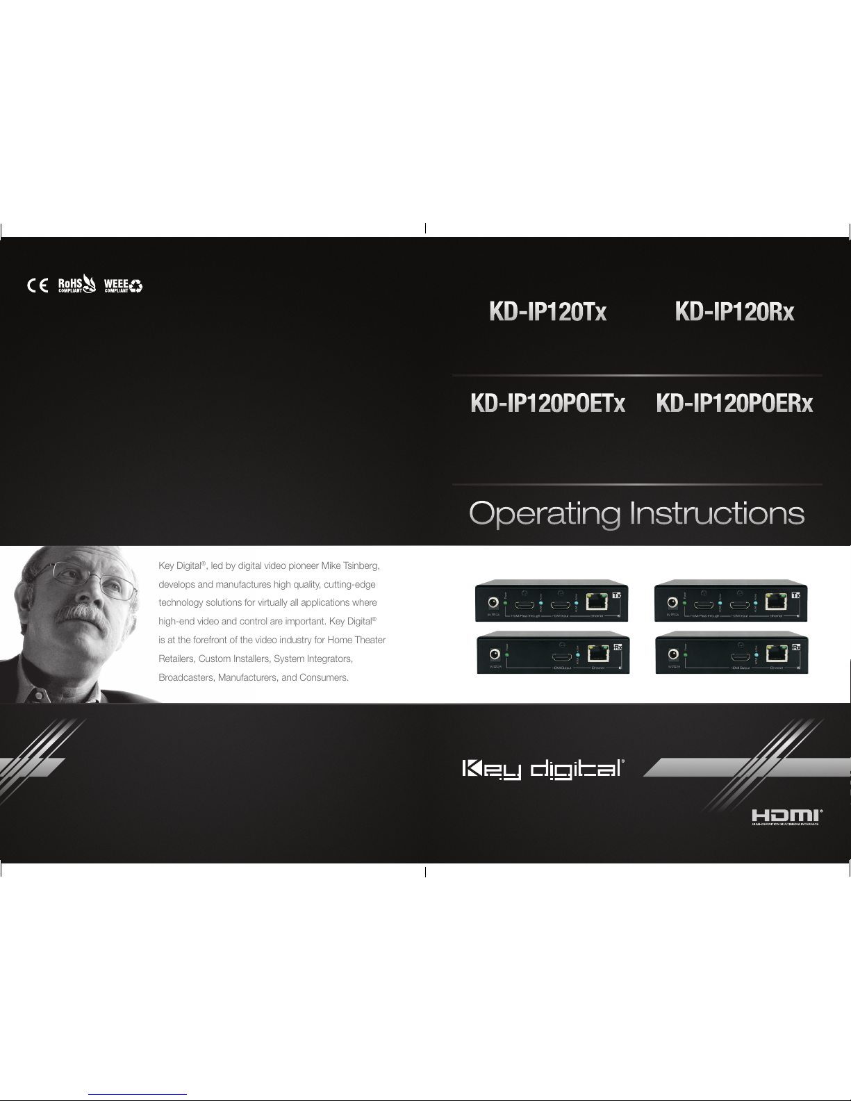
Key Digital®, led by digital video pioneer Mike Tsinberg,
develops and manufactures high quality, cutting-edge
technology solutions for virtually all applications where
high-end video and control are important. Key Digital
®
is at the forefront of the video industry for Home Theater
Retailers, Custom Installers, System Integrators,
Broadcasters, Manufacturers, and Consumers.
The Experts in Digital Video Technology and Solutions
™
KD-IP120Tx
HDMI over IP Transmitter Extender,
supports HDMI Pass-through
KD-IP120POETx
HDMI over IP Transmitter Extender
with Power Over Ethernet,
supports HDMI Pass-through
KD-IP120Rx
HDMI over IP Receiver Extender
KD-IP120POERx
HDMI over IP Receiver Extender
with Power Over Ethernet
Operating Instructions
Rev 0 – May 2016
KD-IP120Tx
KD-IP120Tx
KD-IP120POETx
KD-IP120POERx
Key Digital® Systems :: 521 East 3rd Street :: Mount Vernon, NY 10553
Phone : 914.667.9700 Fax : 914.668.8666 Web : www.keydigital.com
KD-IP120_Manual.indd 2-3 5/3/16 4:52 PM

4 1
Introduction
Key Digital’s HDMI over IP, KD-IP120 & KD-IP120POE, is an expandable HDMI
system where video inputs and video outputs may be scaled to fit any installation.
Add up to 1024 Tx units and an unlimited number of Rx units for the ultimate
custom video solution.
Key Features
› HDMI Pass-through:
Tx unit support HDMI Pass-through to receive video or extract audio
on the transmit side
› Custom System:
Add Tx and Rx extenders to an existing system to expand it up to
1024 Tx units and unlimited amount of Rx units
› Resolution Support:
Supports up to 1080p@60 (2.25Gbps) and compatible
with DVI1.0/HDMI1.3b/HDCP1.x
› Audio Format:
Supports 2ch PCM at 44.1/48kHz
› A/V Bitrate:
Supports Stream Bitrate up to 15Mbps.
› Signal Extension:
Up to 400ft. @ 1080p@60 (2.25Gbps) using CAT5e/6 UTP/STP cable
› KD-IP120POE:
Carry power to Tx and Rx units with a Power Over Ethernet enabled Smart
Managed Switch.
› Web Control Interface:
Reduces installation time and provides basic video setup.
› Full Buffer System
™
:
Manages TMDS re-clocking / signal re-generation, HDCP
authentication to source & display, and EDID Control handshake
› EDID:
EDID libraries readily available to provide the best setup per source
› TMDS re-clocking:
Support for long HDMI connectivity using Key Digital® HDMI cables
› Deep Color Support:
Up to 12 bits/color
› Licensing:
Fully licensed and compatible with all HDMI and HDCP technologies
› Control:
UDP and Web Broswer Control through PC. Control System via Compass Control
MC gateway.
› Major Control System Support:
Compass Control®, AMX®, Control4®, Crestron®, Extron,
Leviton
®
, RTI®, Savant, URC®, etc.
Accessories
› Power Supply: KDPS5V2ASC, 5V/2A, Screw-in type
*Power Supply Not Included with KD-IP120POE*
› Shelf-mount L brackets
› Operating Instructions
Table of Contents
Table of Contents .........................................................4
Introduction ..............................................................1
Recommended Equipment ..................................................2
Quick Setup Guide ........................................................2
Connections .............................................................4
KD-IP120 Tool ............................................................7
Web Interface ...........................................................10
Protocol: RS-232 and TCP/IP Commands......................................11
Specifications ...........................................................12
System Examples ........................................................14
Important Product Warnings & Safety Instructions: ...............................16
How to Contact Key Digital .................................................17
Warranty Information ......................................................17
Always follow the instructions provided in this Operating Manual.
Please check the Key Digital Website for the most up-to-date Manual.
© 2016 Key Digital, Inc. All rights reserved.
KD-IP120_Manual.indd 4-1 5/3/16 4:52 PM
2 3
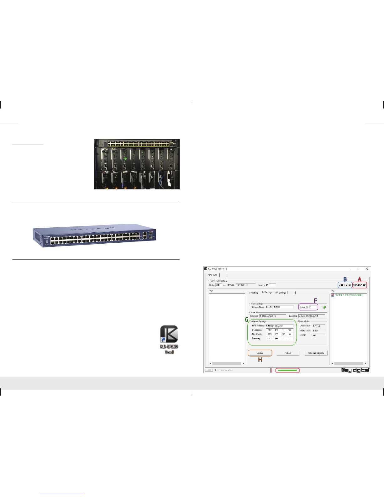
» a. Set the KD-IP120 unit to a specific IP Address.
**Please be aware that IP Addresses cannot clash for all KD-IP120 Units. Please
keep track of IP Address for setup**
» b. Assign a Group ID for every Tx unit and number it as source input number
**Please be aware that Group ID’s cannot clash for Tx Units. Each Tx Unit must
have a unique Group ID. Treat Group ID as Source Input Number. Rx Unit Group
ID’s are not relevant to setup**
» c. The Device Name may be changed to a friendly readable name.
Example, “Rx_Display1” or “Tx_AppleTV”. Don’t forget to label the physical unit to
keep track of it with the copy of the Group ID for Tx Units.
» d. Click Update and the KD-IP120 unit will receive new settings and
reboot (Indicator H)
9. After it resets, disconnect the KD-IP120 unit and repeat Step #7, Step #8, and Step #9
for the remainder units that are not configured yet.
10. Refer to the KD-IP120 Tool section for more information on the below.
After all units are configured, all KD-IP120 units may be assigned to specific zones and
sources in the system while in the Switching tab. Connect HDMI sources to the desired
KD-IP120 Tx units and the HDMI displays to the desired KD-IP120 Rx units. Power may
also be applied.
11. Using the KD-IP120 Tool software, click Network Scan (Indicator A) and all inputs/
outputs will be visible.
12. Set up is complete and switching controls may be done by selecting an output number
and then an input number.
Setup of Tx unit
› Warranty Card
Rack Mounting
› Use KD-RK120PLT (sold separately) to
rack-mount up to 8 KD-IP120 units.
› Units can be secured with the connections
facing outward or inward.
Recommended Equipment
An Ethernet switch with Internet Group Management Protocol (IGMP) is recommended
to maximize the performance of the system. Please check the Key Digital Website for an
updated list of supported IGMP Ethernet Switches.
Quick Setup Guide
One unit at a time, follow the below steps for initial configuration of your Tx and Rx units.
1. Begin with the KD-IP120 Tx/RX units, all input/output devices, and Smart Managed
Switch powered off and power cables removed.
2. Connect power to the Smart Managed Switch. Do not power on Tx/Rx units at once
prior to setup.
3. Connect an Ethernet cable from the PC to the Smart Managed Switch.
4. Ensure proper setup of network router: Using the PC, open the Smart Managed
Switch web portal control and configure the switch by enabling IGMP. Using the PC,
open the Smart Managed Switch web portal control and configure the switch by
enabling IGMP properly.
5.
Download the KD-IP120 Tool software from the Key Digital website
under KD-IP120 product page.
6. Using the PC, run the KD-IP120 Tool application.
7. Connect only one KD-IP120 unit to the Smart Managed Switch and
connect it to power, then click Network Scan (Indicator A). Please wait
until the green loading bar is complete before proceeding (Indicator I).
This process will make it easy to keep track of Rx and Tx locations.
8. Double click on the device, Tx or Rx, and the properties should appear (Indicator G)
KD-IP120_Manual.indd 2-3 5/3/16 4:52 PM
 Loading...