

Key Digital KD-IP1080Tx, KD-IP922DEC, KD-IP922ENC, KD-IP1080Rx, KD-IP120Tx User Manual
...
Verified Network Switches for use with
Key Digital Enterprise AV – HD over IP Systems
Supported Models:
4K Systems:
KD-IP922ENC, KD-IP922DEC
1080p Systems:
KD-IP1080Tx, KD-IP1080Rx
KD-IP120Tx, KD-IP120Rx, KD-IP120POETx, KD-IP120POERx
Important Note:
Setup is different for 4K (KD-IP922) and 1080p (KD-IP1080, KD-IP120) systems.
There are separate setup instructions for each where applicable.
1. Supported Models and System Facts Pg. 2
2. Network Switch Requirements for Enterprise AV Pg. 3
3. Verified Network Switches Table Pg. 4
4. Araknis Setup for 1080p Systems Pg. 6
5. Araknis Setup for 4K Systems Pg. 11
6. Cisco Setup for 1080p Systems Pg. 16
7. Cisco Setup for 4K Systems Pg. 24
8. D-Link Setup for 4K and 1080p Systems Pg. 38
9. Engenius IGMP Setup for 1080p Systems Pg. 46
10. Linksys IGMP Setup for 1080p Systems Pg. 50
11. Linksys IGMP Setup for 4K Systems Pg. 56
12. Netgear IGMP Setup for 4K and 1080p Systems Pg. 65
13. Pakedge S3 IGMP Setup for 4K and 1080p Systems Pg. 70
14. Pakedge SX Series IGMP Setup for 4K and 1080p Systems Pg. 75
15. Titan Networx IGMP Setup for 1080p Systems Pg. 80
16. Wifi Router Setup and Requirements Pg. 88
1 | P a g e
Stream Resolution
Bandwidth
4K @ 60Hz/30Hz
≤ 850 Mbps
1080p @ 60Hz
≤ 250 Mbps
1080i / 720p @ 60Hz
≤ 125 Mbps
Stream Resolution
Bandwidth
1080p @ 60Hz
≤ 15 Mbps
1080i / 720p @ 60Hz
≤ 12 Mbps
480p @ 60Hz
≤ 4 Mbps
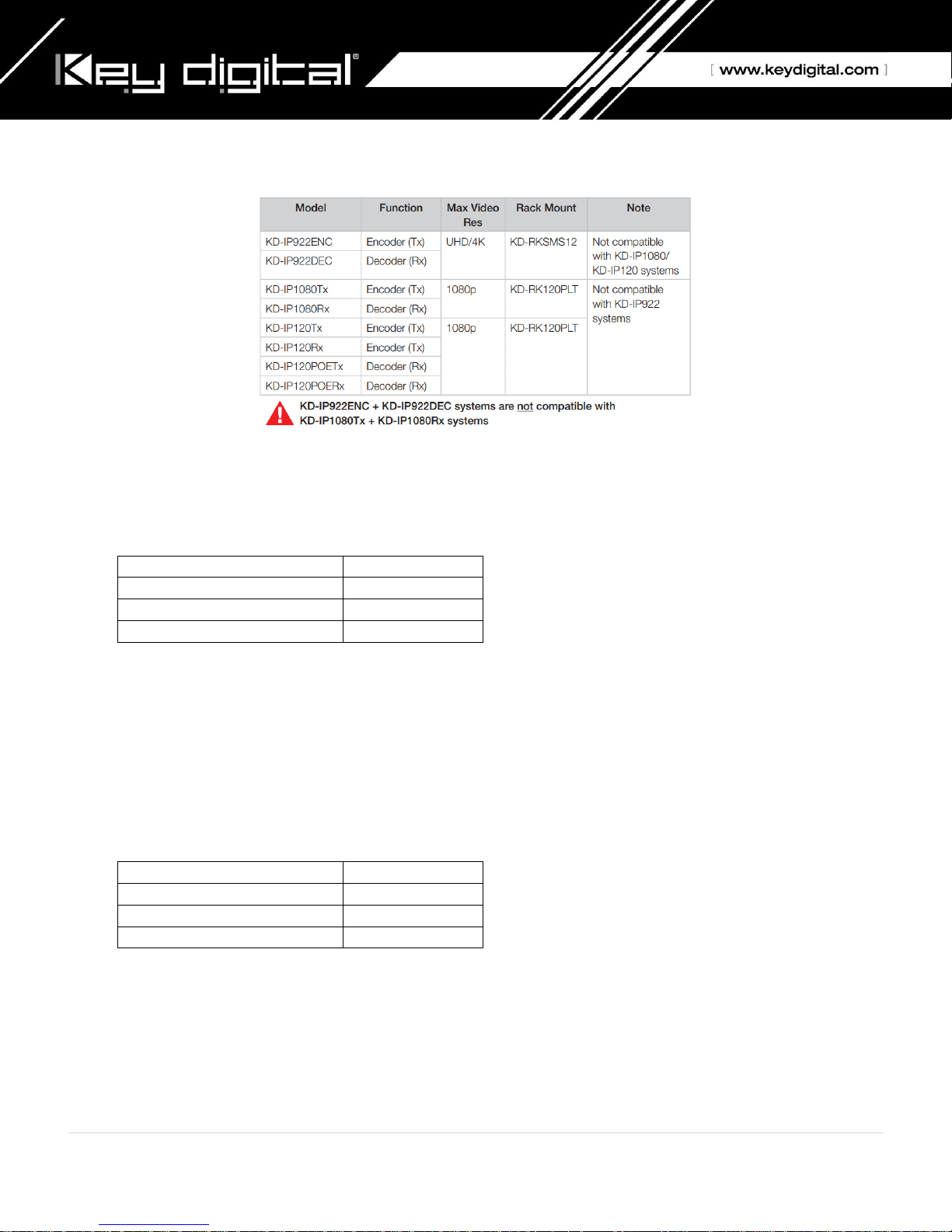
Supported Models:
Key Digital Enterprise AV product family consists of many different models. Not all models are compatible together
System Facts
KD-IP922 models (4K System)
Video Compression Standard: Motion JPEG 2000
Data Stream Bandwidth: < 900 Mbps
Latency: ≈ 40ms @4K. Less at lower resolutions.
PoE Power Consumption: ≤ 9 Watts per unit
Required network cabling: CAT6 UTP/STP, CAT6A, CAT7
KD-IP1080, KD-IP120 models (1080p System)
Video Compression Standard: H.264
Data Stream Bandwidth: < 15 Mbps
Latency: ≈ 400ms @1080p. Less at lower resolutions.
PoE Power Consumption: ≤ 6 Watts per unit
Required network cabling: CAT5e UTP/STP, CAT6 UTP/STP, CAT6A, CAT7
2 | P a g e

Feature
4K System (KD-IP922 models)
1080p System
(KD-IP1080, KD-IP120 models)
IGMP v2
X
X (for non-video preview systems)
IGMP v3
X (for video preview systems)
Bandwidth
1Gbps
100BaseT
8K Jumbo Frame
X PoE
Optional
Optional (excl KD-IP120PoE models)
Network switch Requirements for Enterprise AV
Key Digital’s Enterprise AV is an HDMI over IP system that utilizes multicasting technology to broadcast streams
throughout the network.
Enterprise AV requires a network switch with IGMP (Internet Group Management Protocol) support in order to
direct traffic of the broadcasted streams, ensuring that only the desired decoders receive the stream from the
selected encoder.
For 1080p systems (KD-IP1080, KDIP120 models) that plan to use the video preview feature of the Key Digital App,
IGMP v3 must be enabled. For 1080p or 4K systems that will not use the video preview feature, IGMP v2 is enabled.
KD-IP922 systems require the following IP addresses to be reserved. They cannot be assigned to KD-IP922 units:
192.168.1.1, 192.168.1.50, 192.168.1.90, 192.168.1.100, 192.168.1.150, 192.168.1.200
3 | P a g e

Brand
Model
Port
Number
PoE
KD Lab Verified
KD-IP1080/120
KD Lab Verified
KD-IP922
Araknis
AN-210-SW-R-8-
POE
8
YES
AN-210-SW-F-8-
POE
8
YES
AN-210-SW-R-16-
POE
16
YES
AN-210-SW-F-16-
POE
16
YES
AN-210-SW-R-24-
POE
24
YES
AN-210-SW-F-24-
POE
24
YES
YES
YES
AN-210-SW-F-48-
POE
48
YES
AN-310-SW-R-8
8
AN-310-SW-F-8
8
AN-310-SW-R-16
16
AN-310-SW-F-16
16
AN-310-SW-R-24
24
AN-310-SW-F-24
24 YES
AN-310-SW-R-8-
POE
8
YES
AN-310-SW-F-8-
POE
8
YES
AN-310-SW-R-16-
POE
16
YES
AN-310-SW-F-16-
POE
16
YES
AN-310-SW-R-24-
POE
24
YES
AN-310-SW-F-24-
POE
24
YES
AN-310-SW-F-48-
POE
48
YES
Cisco
SF500-48
48 YES
Catalyst 3850
Series
YES YES
Verified Network Switches
4 | P a g e

Brand
Model
Port
Number
PoE
KD Lab Verified
KD-IP1080
KD Lab Verified
KD-IP922
D-Link
DGS-3630-52PC
52
Yes YES
DGS-3630-52TC
52
DGS-3630-28PC
28
YES
DGS-3630-28SC
28
DGS-3630-28TC
28
Engenius
EGS5212P
8
YES
EGS7228FP
24
YES
EGS7252FP
24
YES
EWS1200D-10T
10
EWS1200D-28T
24
EWS1200D-52T
48
EWS5912FP
8
YES
EWS7928P
24
YES
EWS7928FP
24
YES
EWS7952FP
48
YES
YES
Linksys
LGS552P
52
YES
YES
YES
LGS528P
28
YES
YES
LGS326P
26
YES
YES
LGS318P
18
YES
YES
LGS326MP
26
YES
YES
YES
LGS326P
26
YES
LGS326
26
LGS318P
18
YES
LGS318
18
LGS308MP
8
YES
LGS308P
8
YES
LGS308
8
5 | P a g e

Brand
Model
Port
Number
PoE
KD Lab Verified
KD-IP1080
KD Lab Verified
KD-IP922
Netgear
GS716T
16
GS724T
24
GS748T
48 YES
GS752TP
48
YES
YES
GS728TP
28
YES
Pakedge
S3L-24P
24
YES
YES
YES
SX-8EP
8
SX-8P
8
YES
YES
YES
SX-24
24
SX-24P8
24
YES (8)
SX-24P16
24
YES
(16)
SX-24P
24
YES
(24)
Titan
Networx
TNSS2400P
24
YES
YES
6 | P a g e

IGMP Setup Guide: Araknis
1080p Systems (KD-IP1080, KD-IP120)
1. Before Araknis network switch is configured Key Digital KD-IP120/KD-IP1080 HDMI switch set must be
connected to all HDMI sources/displays/network switches, and configured using Key Digital KD-IP120 Key
Digital Management Software latest version; refer to Key Digital KD-IP120/KD-IP1080 configuration manual.
2. Power-up all the system components. Using Key Digital KD-IP120 Key Digital Management Software, switch
All Outputs -> Through at switching page.
3. IMPORTANT: Disconnect all the DHCP devices like routers, servers from the Araknis network switch.
4. Locate a pinhole “RESET” button at the front panel left bottom corner of your Araknis network switch. Using
a paper clip press and hold a reset button for more than 10 seconds and then release. Wait while the device
is restarted and ready to use (about 5min).
5. IMPORTANT: At this point all the displays should be displaying distorted randomly flashing video images.
6. Connect your PC to the Araknis network switch directly using a network cable.
7. If you have not done yet, configure your PC’s IP address to the same range as the switch (default
192.168.20.xxx).
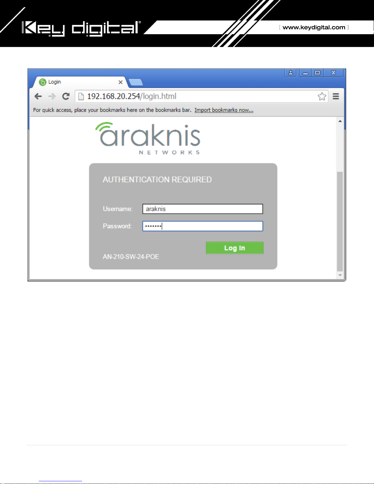
8. Enter the switch’s IP address (default is 192.168.20.254) in your browser and press ENTER.
9. Enter user name and password (default is “araknis” for both). Then click Log In.
7 | P a g e

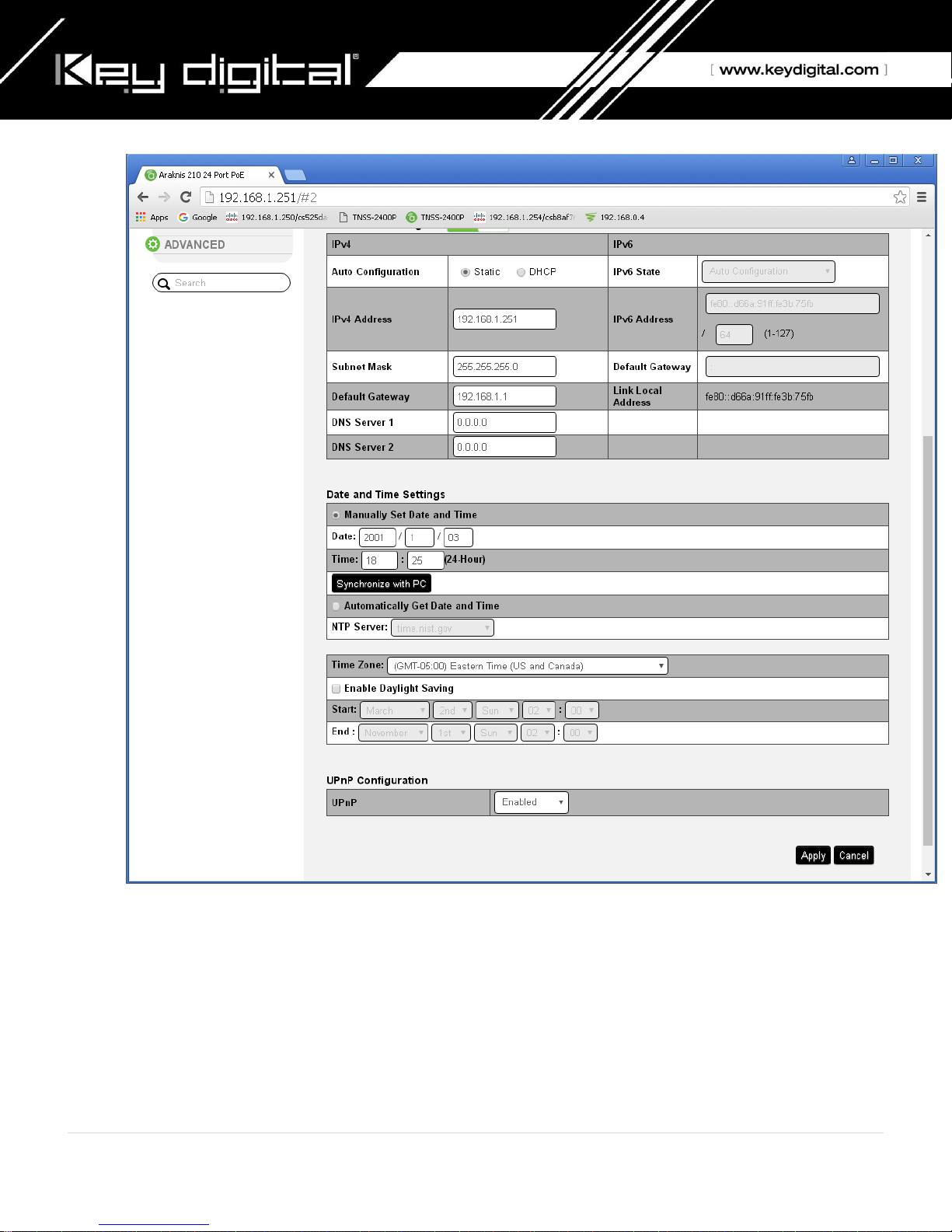
10. Navigate to Settings -> System. Under IP Address Settings elect Static. Change an IP address to
192.168.1.251, Subnet Mask to 255.255.255.0, Default Gateway to 192.168.1.1 (in this case), and at the
bottom click Apply. If you are setting up multiple network switches it is recommended to set first one to
192.168.1.251, second to 192.168.1.252, and so on, and each switch must be set individually same way as
described below.
8 | P a g e
11. Page will refresh. Configure your PC’s IP address to the same range as the switch (default 192.168.1.xxx).
Enter the switch’s IP address (default is 192.168.1.251) in your browser and press ENTER.
12. Make sure the settings remain as above.
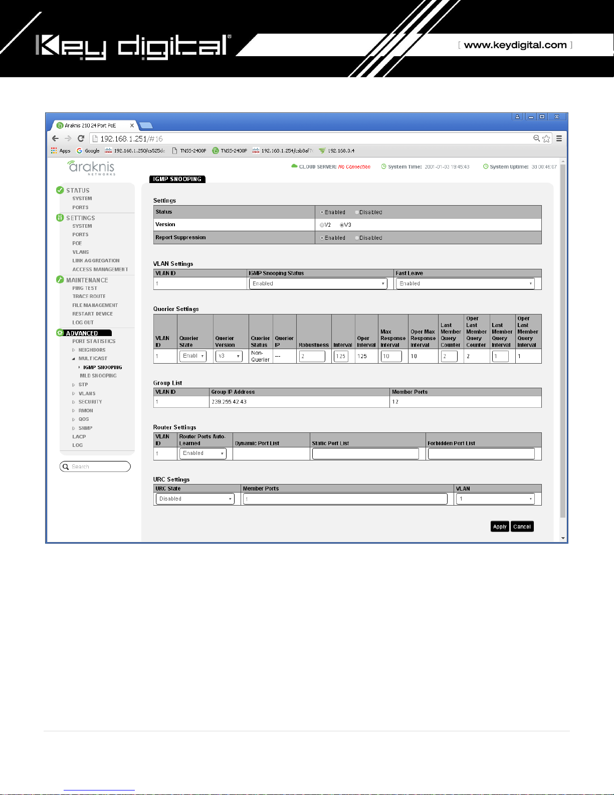
13. Navigate to Advanced -> Multicast -> IGMP Snooping. Under Settings select Enable for Status, V3 for
Version, and Enable for Report Suppression. Under VLAN Settings / VLAN ID 1 select Enable for IGMP
Snooping Status and Enable for Fast Leave. Under Querier Settings / VLAN ID 1 select Enable for Querier
State, V3 for Querier Version and make sure all other setting are exactly as shown below. Click Apply.
9 | P a g e
14. IMPORTANT: At this point all the displays should be displaying stable running video from the selected
sources. If you do not have them displaying properly, than network switch is configured incorrectly.
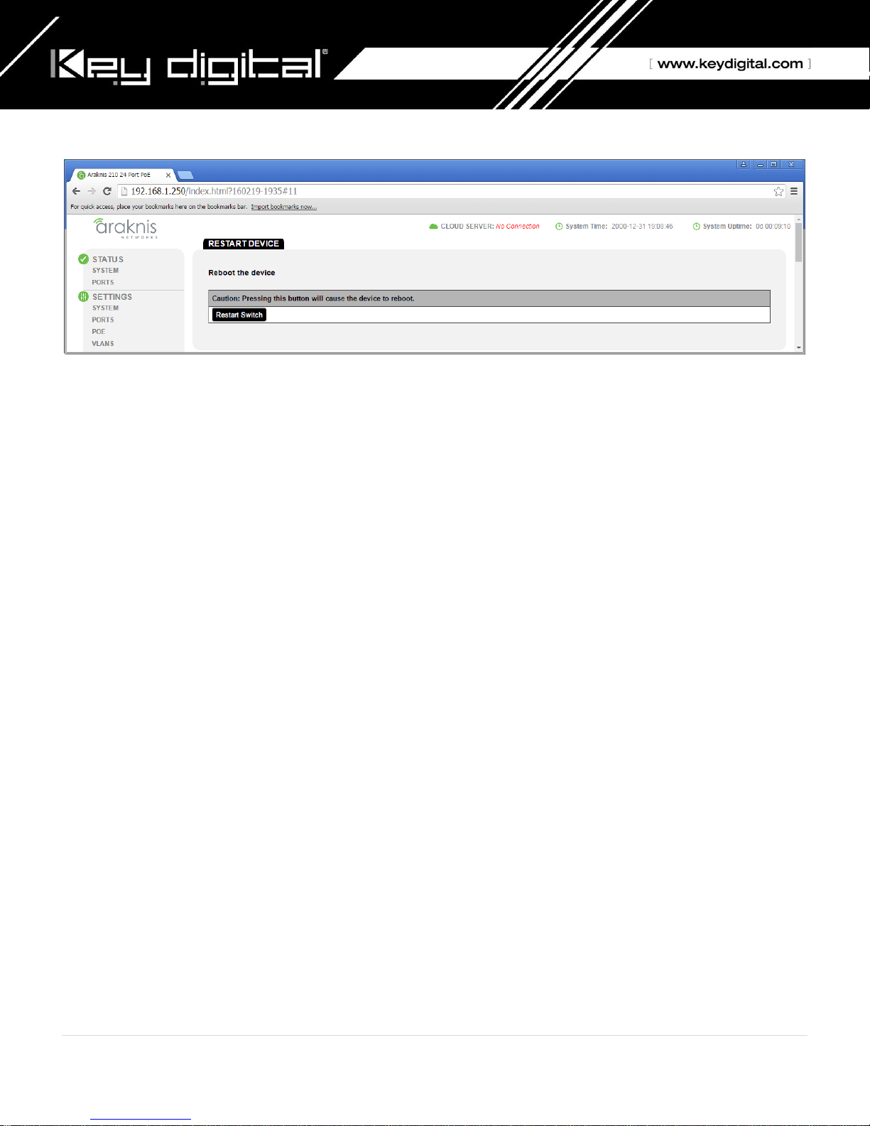
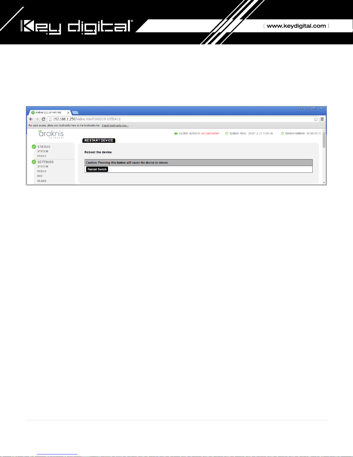
15. Navigate to Maintenance -> Restart Device and click Restart Switch. After switch is rebooted and back to
normal log in again, check all the settings again.
10 | P a g e
16. IMPORTANT: Now you can connect back you DHCP equipment (routers, servers and so on).
17. Power down Araknis network switch and power it up back again. Wait for the whole system to start and
until you can see video on your displays.
18. Log in to your Araknis network switch again and make sure that IGMP settings are intact.
19. Rescan your components with Key Digital KD-IP120 Key Digital Management Software and make sure HDMI
video switch is functional.
20. At this point your Araknis network switch is set and ready to use.
11 | P a g e

IGMP Setup Guide: Araknis
4K Systems (KD-IP922)
1. Before Araknis network switch is configured Key Digital KD-IP120/KD-IP1080 HDMI switch set must be
connected to all HDMI sources/displays/network switches, and configured using Key Digital KD-IP120 Key
Digital Management Software latest version; refer to Key Digital KD-IP120/KD-IP1080 configuration manual.
2. Power-up all the system components. Using Key Digital KD-IP120 Key Digital Management Software, switch
All Outputs -> Through at switching page.
3. IMPORTANT: Disconnect all the DHCP devices like routers, servers from the Araknis network switch.
4. Locate a pinhole “RESET” button at the front panel left bottom corner of your Araknis network switch. Using
a paper clip press and hold a reset button for more than 10 seconds and then release. Wait while the device
is restarted and ready to use (about 5min).
5. IMPORTANT: At this point all the displays should be displaying distorted randomly flashing video images.
6. Connect your PC to the Araknis network switch directly using a network cable.
7. If you have not done yet, configure your PC’s IP address to the same range as the switch (default
192.168.20.xxx).
8. Enter the switch’s IP address (default is 192.168.20.254) in your browser and press ENTER.
9. Enter user name and password (default is “araknis” for both). Then click Log In.
12 | P a g e
10. Navigate to Settings -> System. Under IP Address Settings elect Static. Change an IP address to
192.168.1.251, Subnet Mask to 255.255.255.0, Default Gateway to 192.168.1.1 (in this case), and at the
bottom click Apply. If you are setting up multiple network switches it is recommended to set first one to
192.168.1.251, second to 192.168.1.252, and so on, and each switch must be set individually same way as
described below.
13 | P a g e

11. Page will refresh. Configure your PC’s IP address to the same range as the switch (default 192.168.1.xxx).
Enter the switch’s IP address (default is 192.168.1.251) in your browser and press ENTER.
12. Make sure the settings remain as above.
13. Navigate to Advanced -> Multicast -> IGMP Snooping. Under Settings select Enable for Status, V2 for
Version, and Enable for Report Suppression. Under VLAN Settings / VLAN ID 1 select Enable for IGMP
Snooping Status and Enable for Fast Leave. Under Querier Settings / VLAN ID 1 select Enable for Querier
State, V2 for Querier Version and make sure all other setting are exactly as shown below. Click Apply.
14 | P a g e

14. Enter Settings -> Ports and set Jumbo Frame size to 9216 bytes, enabling the required 8K jumbo frame
support feature.
15 | P a g e
15. IMPORTANT: At this point all the displays should be displaying stable running video from the selected
sources. If you do not have them displaying properly, then network switch is configured incorrectly.
16. Navigate to Maintenance -> Restart Device and click Restart Switch. After switch is rebooted and back to
normal log in again, check all the settings again.
17. IMPORTANT: Now you can connect back you DHCP equipment (routers, servers and so on).
18. Power down Araknis network switch and power it up back again. Wait for the whole system to start and
until you can see video on your displays.
19. Log in to your Araknis network switch again and make sure that IGMP settings are intact.
20. Rescan your components with Key Digital KD-IP120 Key Digital Management Software and make sure HDMI
video switch is functional.
21. At this point your Araknis network switch is set and ready to use.
16 | P a g e

IGMP Setup Guide: Cisco SF500-48
1080p Systems (KD-IP1080, KD-IP120)
Note: Compatible with KD-IP1080, KD-IP120 Enterprise AV Systems Only
1. Before Cisco network switch is configured Key Digital KD-IP120/KD-IP1080 HDMI switch set must be
connected to all HDMI sources/displays/network switches, and configured using Key Digital KD-IP120 Key
Digital Management Software latest version.
2. Power-up all the system components. Using Key Digital KD-IP120 Key Digital Management Software, switch
All Outputs -> Through at switching page.
3. IMPORTANT: Disconnect all the DHCP devices like routers, servers from the Cisco network switch.
4. Locate a pinhole “RESET” button at the front panel left bottom corner of your Cisco network switch. Using a
paper clip press and hold a reset button for more than 10 seconds and then release. Wait while the device
is restarted and ready to use (about 5min).
5. IMPORTANT: Make sure the green “SYSTEM”LED next to the pinhole “RESET” button is flashing.
6. IMPORTANT: At this point all the displays should be displaying distorted randomly flashing video images.
7. Connect your PC to the Cisco network switch directly using a network cable.
8. If you have not done yet, configure your PC’s IP address to the same range as the switch (default
192.168.1.xxx).
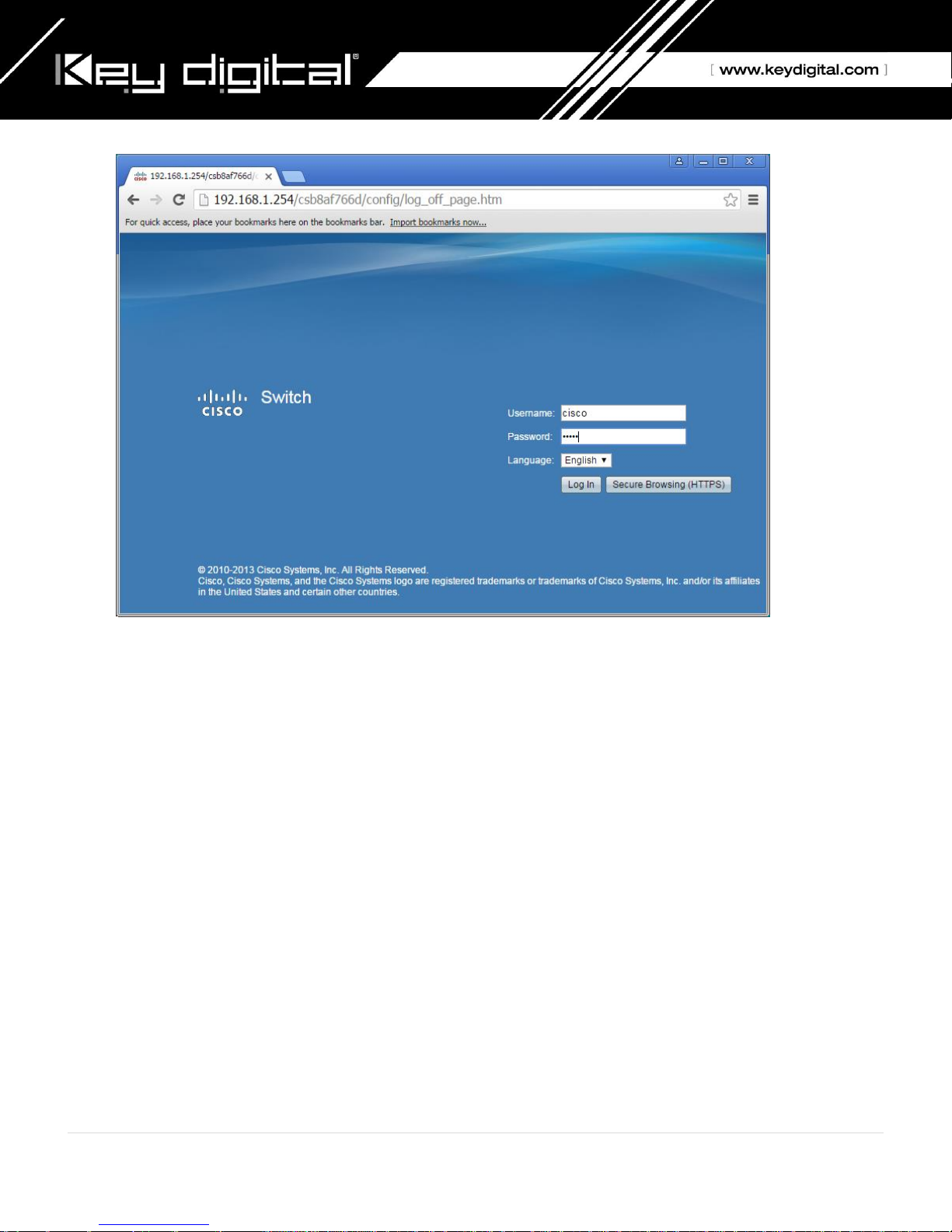
9. Enter the switch’s IP address in your browser and press ENTER (check the user manual for a default IP
address - it is usually 192.168.1.254).
10. Enter user name and password (check the user manual for a default user name and password; it is usually
“cisco” for both). Then click Log In.
17 | P a g e
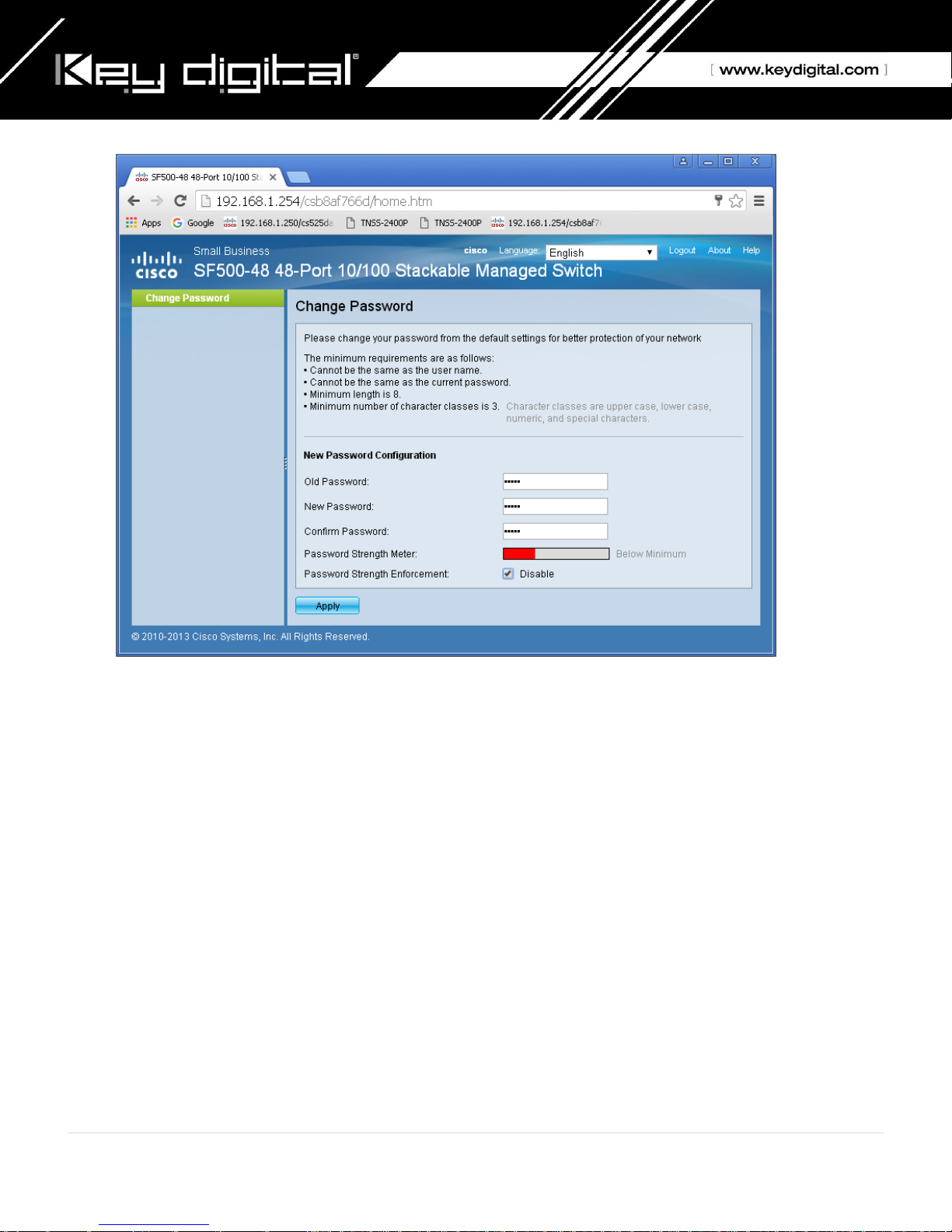
11. Change Password screen will appear. Enter old and then new password two times as at the picture below
and click Apply.
18 | P a g e
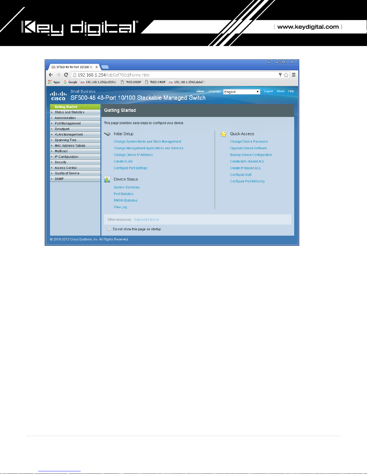
12. Getting Started screen will appear.
19 | P a g e
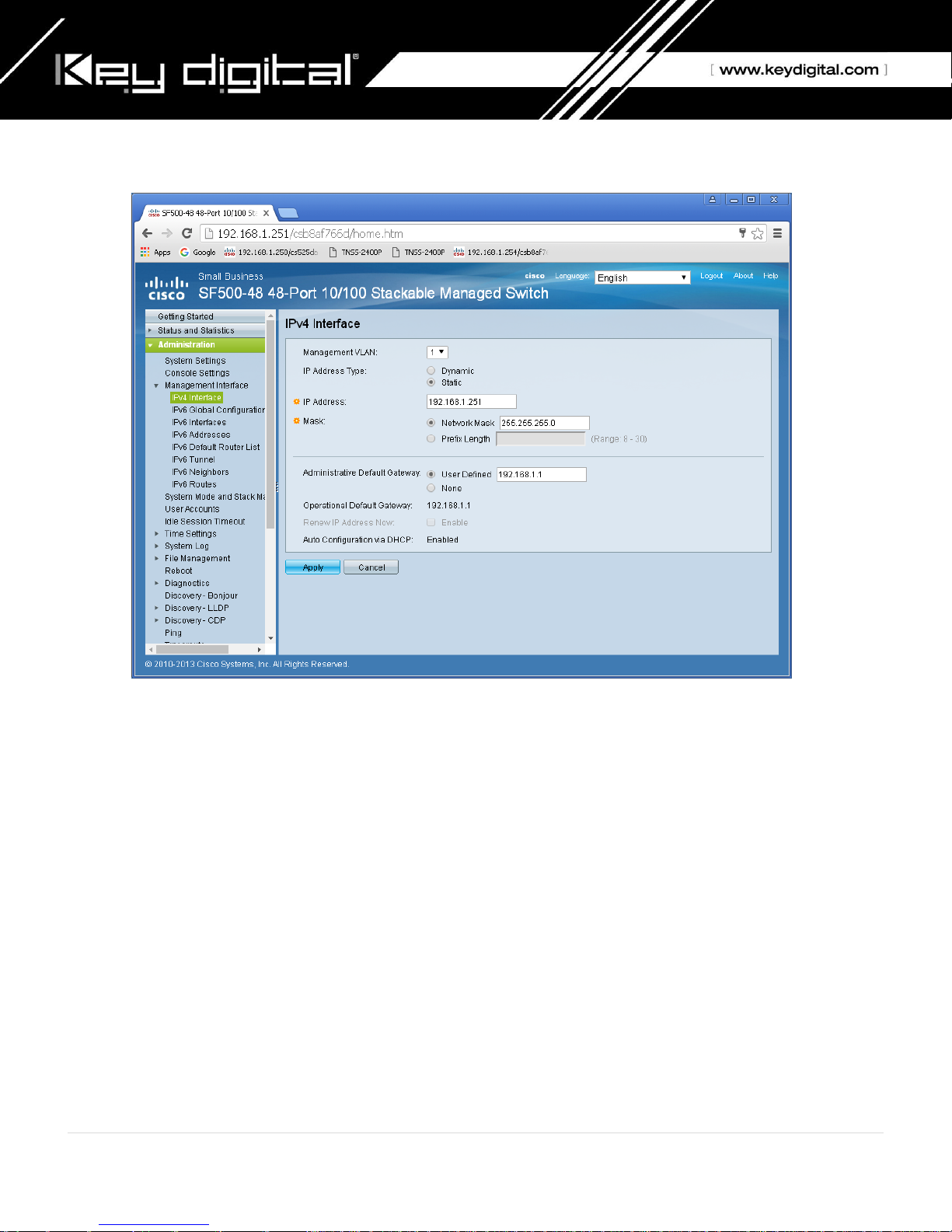
13. Navigate to Administration -> Management Interface -> IPv4 Interface. Select “1” under Management
VLAN. Select Static for IP Address Type. Change an IP address to 192.168.1.251. If you are using multiple
network switches it is recommended to set first one to 192.168.1.251, second to 192.168.1.252, and so on.
Leave Network Mask as 255.255.255.0, set Administrative Default Gateway as User Defined and enter
your router IP address (in this case: 192.168.1.1), then click Apply.
14. Click OK to confirm.
20 | P a g e
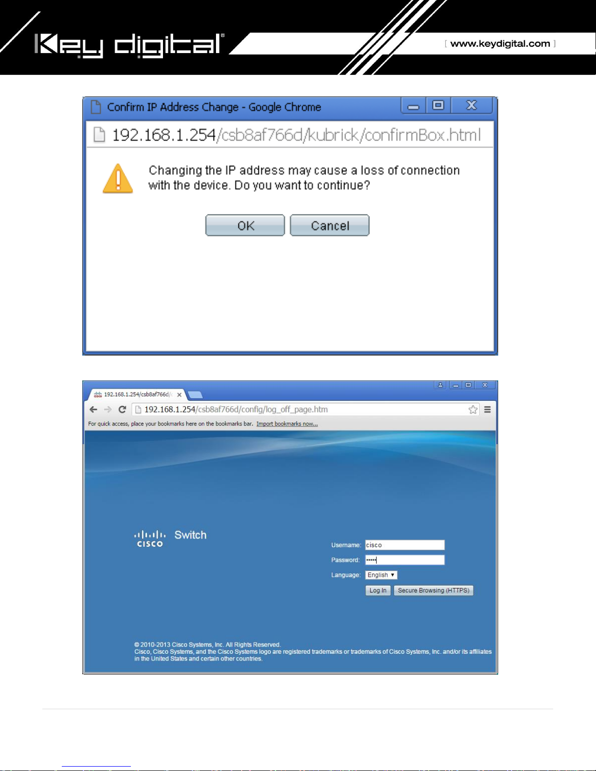
15. Log in again using new password and new IP address.
21 | P a g e
16. Confirm all the administration page settings as at the picture below.
17. Navigate to Multicast -> Properties. Check Enable box next to the Bridge Multicast Filtering Status box.
Make sure the other settings are exactly as shown below. Then click Apply.
22 | P a g e
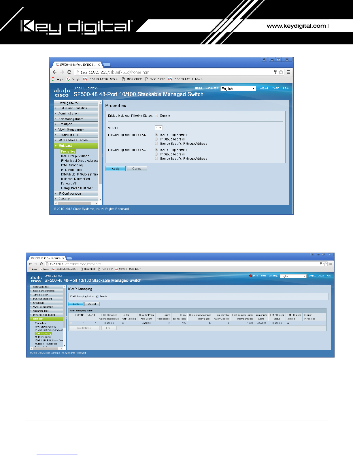
18. Navigate to Multicast -> IGMP Snooping. Check the IGMP Snooping Status: Enable box and click Apply.
19. Click on a radio button on the left and then click Edit. New window will appear.
23 | P a g e
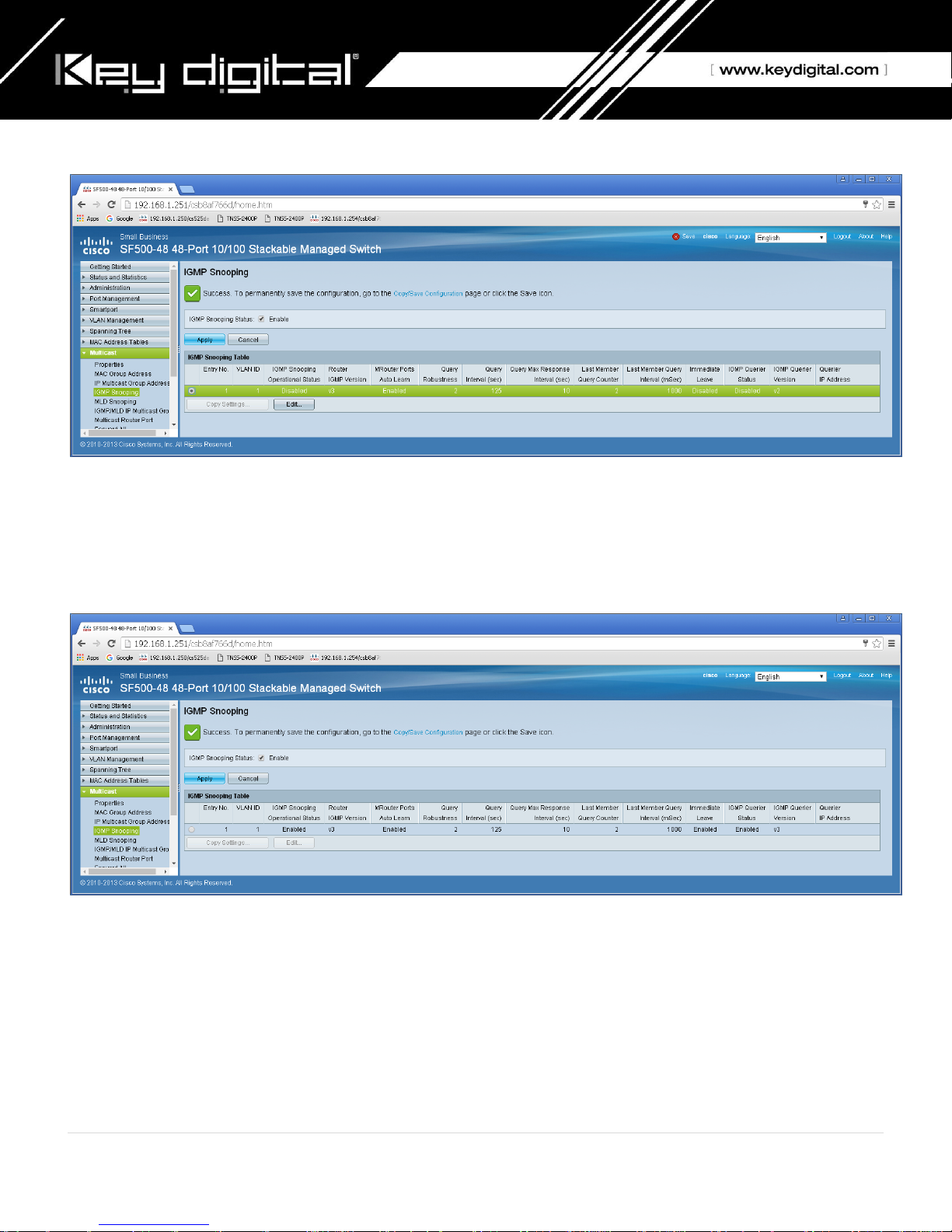
20. Click on a radio button on the left and then click Edit. New window will appear. Select “1” for VLAN ID.
Check Enable box under IGMP Snooping Status. Check Enable box under Immediate Leave. Check Enable
box under IGMP Querier Status. Select User Defined next to Administrative Querier Source IP Address:
and select 192.168.1.1. For IGMP Querier Version: select IGMPV3. Then click Apply and Close. Make sure
all the setting are exactly as shown at the picture below.
21. IMPORTANT: At this point all the displays should be displaying stable running video from the selected
sources. If you do not have them displaying properly, than network switch is configured incorrectly.
22. On the top of the page click on flashing “x Save”. For Source File Name: select Running configuration. For
Destination File Name: select Startup configuration. Check the selections and make sure they are exactly
as shown below. Click Apply.
24 | P a g e
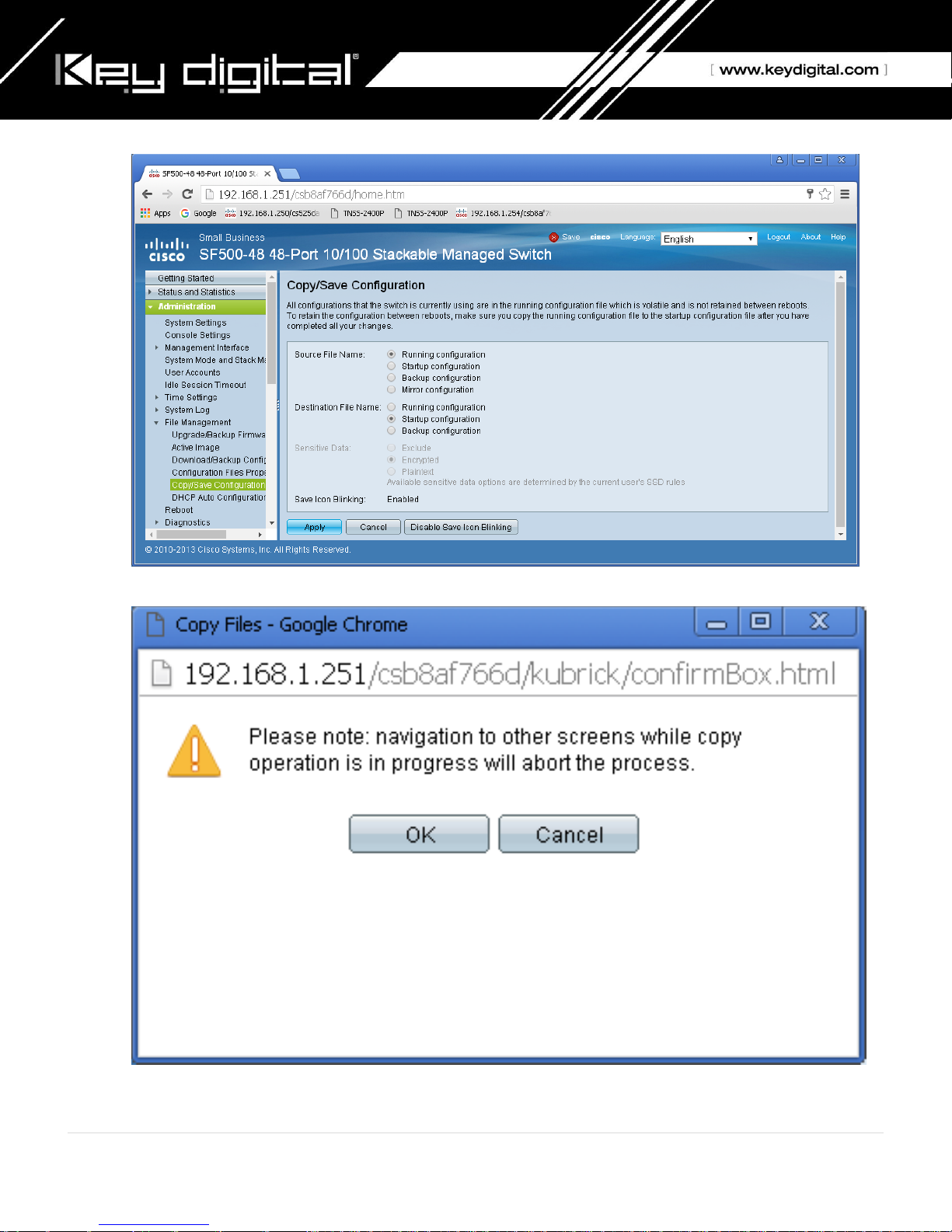
23. Click Apply to confirm.
24. Click Done.
25 | P a g e

25. IMPORTANT: Now you can connect back you DHCP equipment (routers, servers and so on).
26. Power down Cisco network switch and power it up back again. Wait for the whole system to start and until
you can see video on your displays.
27. Log in to your Cisco network switch again and make sure that IGMP settings are intact:
28. Rescan your components with Key Digital KD-IP120 Key Digital Management Software and make sure HDMI
video switch is functional.
29. At this point your Linksys network switch is set and ready to use.
26 | P a g e
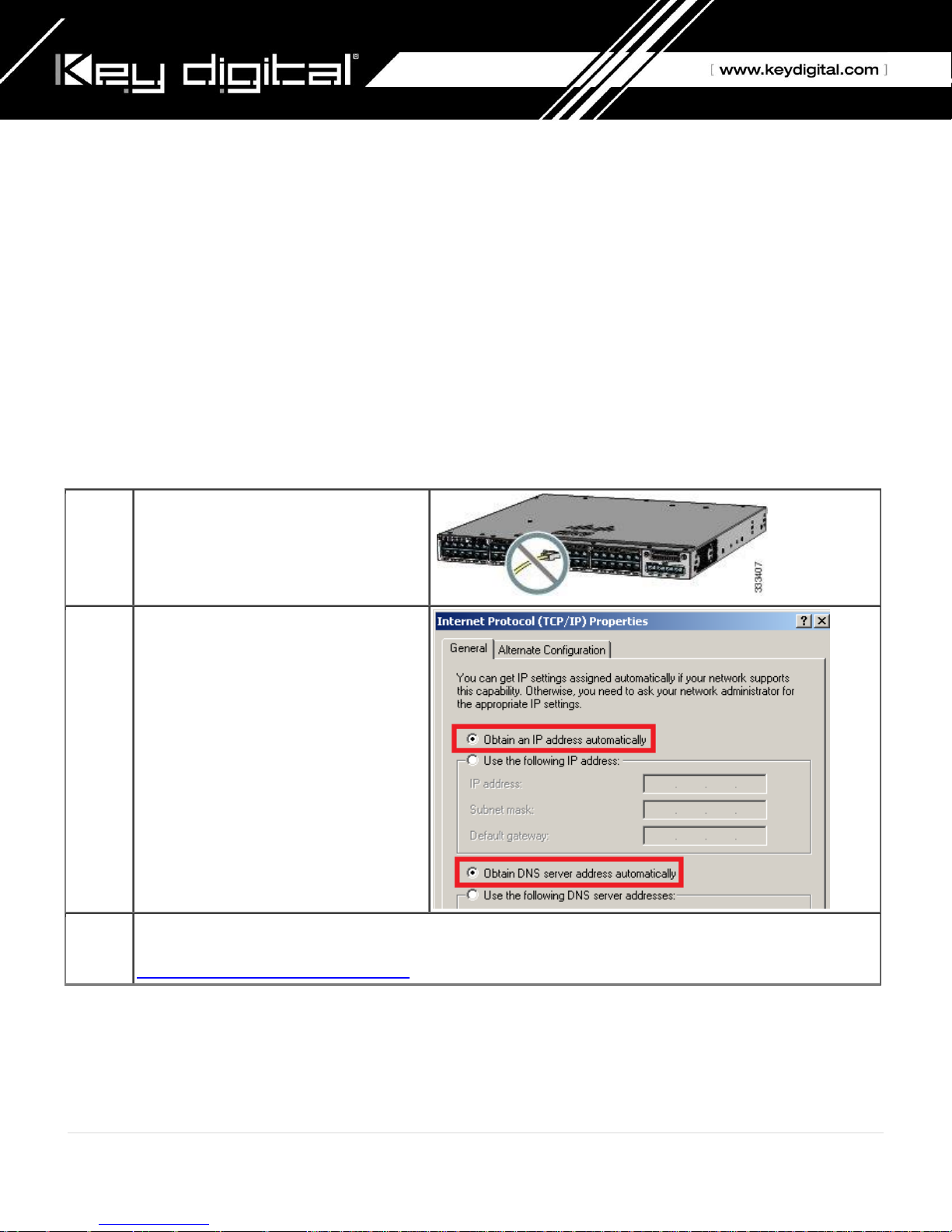
Step 1
Make sure that nothing is connected to
the switch.
Step 2
During Express Setup, the switch acts as
a DHCP server. If your PC or laptop has a
static IP address, temporarily change
your PC or laptop settings to DHCP.
Note. Do not connect LAN cable from
your PC or laptop to Cisco’s switch until
Step 7.
Step 3
Install the power supply modules. See the “Power Supply Installation” chapter in the Catalyst 3850 Switch
Hardware Installation Guide for instructions.
http://www.cisco.com/go/cat3850_hw
IGMP Setup Guide: Cisco C3850 Series
4K Systems (KD-IP922)
Cisco Catalyst 3850 series
This guide describes how to use Express Setup to initially configure your Catalyst 3850 switch. We have modified
original Express Setup guide from Cisco to help out you install it easily. For more installation and configuration
information, see the Catalyst 3850 documentation on Cisco.com.
Running Express Setup & Configuration Setup for KD-IP922
Use Express Setup to enter the initial IP information. This action enables the switch to connect to local routers and
the Internet. You can access the switch through the IP address for further configuration.
Note : Even you already finish Express Setup on your switch, please check every step one by one.
27 | P a g e
 Loading...