

Key Digital KD-HDMS5X11, KD-HDMS2X14, KD-HDMS3X13, KD-HDMS4X12, KD-HDMS6X10 Setup Manual
...
Key Digital® Hercules Series™ KD-HDMS8x8 is a HDMI Matrix Switcher capable of switching
up to 8 HDMI/DVI Video Sources/Inputs to 8 independent Zones/Outputs via HDMI and CAT5.
Features card slot architecture providing flexible Input/Output configurations.
KD-HDMS8X8
8 Inputs to 8 Outputs HDMI Matrix Switcher
Also Available in Configurable Models Below:
KD-HDMS1X15, 2X14, 3X13, 4X12, 5X11, 6X10, 7X9
KD-HDMS15X1, 14X2, 13X3, 12X4, 11X5, 10X6, 9X7
Set Up Guide

Page 2
Table of Contents
About KD-HDMS8X8. . . . . . . . . . . . . . . . . . . . . . . . . . . . . . . . . . . . . . . . . . . . . . . . . . . . . . . . . 2
Connections, LCD and Button Map . . . . . . . . . . . . . . . . . . . . . . . . . . . . . . . . . . . . . . . . . . . . . . 3
Application Example . . . . . . . . . . . . . . . . . . . . . . . . . . . . . . . . . . . . . . . . . . . . . . . . . . . . . . . . . 5
Quick Setup Guide . . . . . . . . . . . . . . . . . . . . . . . . . . . . . . . . . . . . . . . . . . . . . . . . . . . . . . . . . . 6
IR Remote Command List . . . . . . . . . . . . . . . . . . . . . . . . . . . . . . . . . . . . . . . . . . . . . . . . . . . . .12
RS-232 Control Codes . . . . . . . . . . . . . . . . . . . . . . . . . . . . . . . . . . . . . . . . . . . . . . . . . . . . . . .12
Specifications . . . . . . . . . . . . . . . . . . . . . . . . . . . . . . . . . . . . . . . . . . . . . . . . . . . . . . . . . . . . . .16
Important Product Warnings & Safety Instructions . . . . . . . . . . . . . . . . . . . . . . . . . . . . . . . . . . .18
How to Contact Key Digital
®
. . . . . . . . . . . . . . . . . . . . . . . . . . . . . . . . . . . . . . . . . . . . . . . . . . . .19
Warranty Information . . . . . . . . . . . . . . . . . . . . . . . . . . . . . . . . . . . . . . . . . . . . . . . . . . . . . . . . .19
About KD-HDMS8X8
Description
» HDMI Matrix Switcher capable of switching up to 8 HDMI/DVI Video Sources/Inputs to 8
independent Zones/Outputs via HDMI and CAT5. Custom configurable to 1x15, 2x14, 3x13,
4x12, 5x11, 6x10, 7x9, 9x7, 10x6, 11x5, 12x4, 13x3, 14x2 and15x1 combinations.
Key Features
» Full switching of 3 independent matrixes: Video, Audio and Control
» Supports all SD, HD, and VESA (VGA, SVGA, XGA, WXGA, SXGA, UXGA) resolutions
up to 1080p (60Hz & 50Hz)
» SD & HD: 480i, 480p, 720p, 1080i, 1080p
» VESA / VGA (RGBHV): From 640x480p up to 1920x1200p
» Full support for HDMI
®
1.3a/b with HDCP, 3D Ready, 4K Resolution Support
» Supports lossless compressed digital audio (Dolby
®
TrueHD, Dolby® Digital Plus
and DTS
™
-HD Master Audio)
» Internal EDID Library features 8 default EDID configurations in addition to native
EDID data from any Output/Display
Key Benefits
» Transmits 1080p/60Hz resolution up to 140 ft, 1080p/24, 1080i, 720p and 480i/p resolutions
up to 270 ft, when used with KD-BBRX receiver Baluns
» Video, Audio, IR and RS-232 distribution via a single CAT5 cable
» Fully automatic CAT5 cable equalization, with optional manual calibration
» 16 active outputs (8 HDMI/DVI and 8 CAT5) enables flexible integration
» Full Audio control per output for volume, treble, bass, balance, and lip-sync from analog or
2ch. PCM HDMI digital sources
© 2010 Key Digital, Inc. All rights reserved.
Page 3
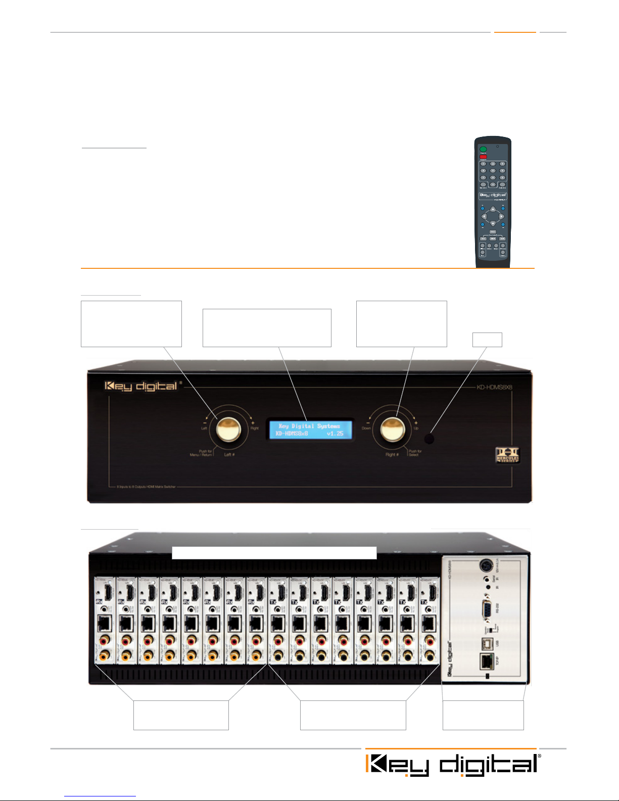
Connections, LEDs and Button Map
Front Panel
Main Control Panel
Please see p. 4 for
detailed description
Input Cards 1-8 (KD-HDUIC)
Please see p. 4 for
detailed description
Looking at the rear panel, card slots are numbered from left to right
Output Cards 1-8 (KD-HDUOC)
Please see p. 4 for
detailed description
LCD Screen
Displays Menu selections, Input and
Output information, system settings and
status information
Right Selector
Use to access sub-menus
within the Main Menu.
(see pg.8 for complete
operating instructions)
Left Selector
Use to access Main Menu
and select sub-menu choices.
(see pg.7 for complete
operating instructions)
IR Eye
Rear Panel
» Serial IR, Optical IR, Front Panel Control, Discrete Remote Codes, RS-232 and TCP/IP.
Supports major control systems such as AMX
®
, Colorado vNet®, Control4®, Crestron®, RTI®,
Savant, Universal
®
, Xantech
®
Accessories
» External +12V/8.33A (100W) Power Supply – KD-PS12V8A
» IR Remote control with two batteries
» Operating Instructions
» HDMI Cable Clips (16)
» 6ft USB Data Cable
Page 4
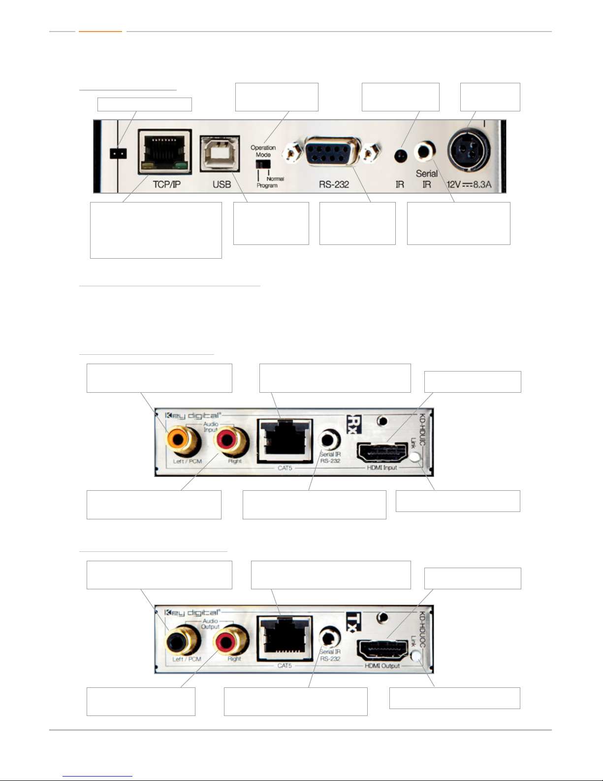
Main Control Panel
Rx Input Card (KD-HDUIC)
Tx Output Card (KD-HDUOC)
HDMI Input and Output Numbering
The KD-HDMS8x8 in its default configuration contains 8 Input cards and 8 Output cards. The Input
cards are addressed from 01-08, and the Output cards from 01-08.
Power
12V/8.33A (100W)
Power Supply
Rear IR Eye (Receiver)
Rear IR receiver for
remote control
Operation Mode Switch
Switch to “Program” mode
when updating firmware
For manufacturers use only
Serial IR
To Input from Control interface
for controlling unit via Serial IR
and IR routing
RS-232
The main RS-232/DB9
port for interfacing with
a control system.
USB
The USB port is for
software upgrades only.
It is not used for control
interface.
TCP/IP
This is the main TCP/IP port for interfacing
with control systems. It supports the same
control commands as the RS-232 port
and it can support TCP/IP to RS-232
conversion & routing and TCP/IP to serial
IR conversion & routing.
Serial IR / RS-232
Use the KD-HDMS as a Control Router for
devices integrated into your system
Serial IR / RS-232
Use the KD-HDMS as a Control Router for
devices integrated into your system
Left Analog Audio / PCM Audio Input
Supports Left channel Analog Audio Input or
use for Coaxial Digital Audio Input
Left Analog Audio / PCM Audio Output
Send Left channel Analog Audio or Coaxial
Digital Audio to your Display or other devices
CAT5 Input
Integrate a remote source by using the KD-BBTX
Transmit Balun to feed the CAT5 inputs
CAT5 Output
Use the KD-BBRX Receive Balun to carry Video,
Audio, and Control to your Display (or other) devices
Right Analog Audio Input
Supports Right channel Analog Audio Input
Right Analog Audio Output
Send Right channel Analog Audio
to your Receiver or other devices
Link LED
Indicates that input connection is stable
Link LED
Indicates that output connection is stable
HDMI Input
To Input source components
HDMI Output
To Output to Display
Page 5
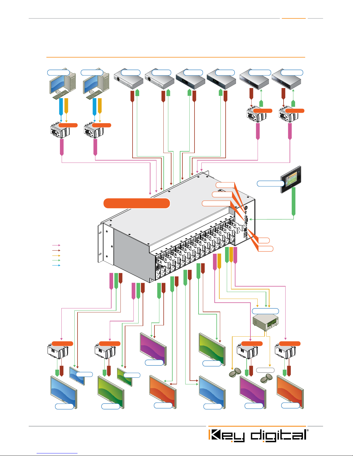
Application Example
DVI Video*
DVI Video*
L/R/PCM
L/R/PCM
CAT5/5e/6
L/R/PCM
CAT5/5e/6
CAT5/5e/6
CAT5/5e/6
CAT5/5e/6
L/R/PCM
CAT5/5e/6
CAT5/5e/6
CAT5/5e/6
Speakers
HDMI
HDMI
Blu-Ray
Satellite 1
Desktop PC Desktop PC
Display 8Display 4
Control System
DVI
HDMI/DVI
Audio
CAT5/6/7
IR/RS-232
IR
HDMI
HDMI
Blu-Ray
IR
IR
HDMI
IR
HDMI
IR
HDMI
IR
IR/RS-232
IR/RS-232 & TCP/IP
IR
HDMI
IR
HDMI
IR
HDMI
IR
IR/RS-232
IR/RS-232
HDMI
HDMI
IR/RS-232
HDMI
IR/RS-232
HDMI
IR/RS-232
HDMI
IR/RS-232
HDMI
Display 7
Display 3
Display 2
Display 5
Display 1 Display 6
Display 2a
Display 1a
(mirrored)
(mirrored)
Satellite 2 Cable 1 Cable 2
KD-BBTXKD-BBTX
KD-BBTX KD-BBTX
KD-BBRXKD-BBRXKD-BBRXKD-BBRX
KD-HDMS8X8
Transmits:
»1080p/60Hz resolution up to 140 ft
»1080p/24, 1080i, 720p and 480i/p resolutions up to 270 ft
» When used with KD-BBRX Receiver Baluns
RS232 Control
Serial IR
USB
TCP/IP
Optical IR
Surround Rcvr.
*To connect DVI use HDMI to DVI adapters
270’
180’
200’
150’

Page 6
Quick Setup Guide
Initial Setup & Operation for HDMI via Front Panel
The KD-HDMS8x8 is set by default to HDMI Input. To change these default settings please see
“Initial Setup & Operation via CAT5 Baluns” section below.
1. Insert HDMI cables into card slots 1 through 16
» Slots 1-8 are labeled Rx, and are Input Card Slots 1-8.
» Slots 9-16 are labeled Tx, and are Output Card Slots 1-8.
» Connect your source components to the Input cards
» Connect your displays to the Output cards
» Power up all sources and displays
2. Establish an HDMI Handshake for Each Source
» Push the left selector to access the Main Menu choices
» Using the left selector, scroll to the “7-EDID Setup” Menu
» Press the right selector to navigate to the EDID sub-menus
» With the left selector, scroll to the Input source you wish to copy the EDID to
» Using the right selector, scroll to the HDMI or CAT5 Output you wish to establish an HDMI
handshake for, or select a Default EDID 01-08 from the EDID library (see pg.10)
» Press the right selector to set the Handshake for that combination
» Continue this procedure for all Inputs
» The EDID control and HDMI input set up is stored in a non-volatile memory back up and is
only required during initial set up or when a new display or source is added to the system.
» Establish a default handshake for ALL Inputs:
» Using the ‘7-EDID Setup’ Menu, select ‘ALL Inputs’ and scroll to the Output number
you wish to copy the EDID from (HDMI, CAT5 or a Default EDID setting) and press
the right selector
3. Switching via Front Panel
» Push the left selector to access the Main Menu choices
» Using the left selector, scroll to the “1-Video Switch” Menu
» Press the right selector to navigate to the Video Switch sub-menus
» Using the left selector, scroll to the Output you wish to select
» Using the right selector, scroll to the Input you wish to select
» Finally, press the right selector to make the switch
4. Sending your output via KD-BBRX CAT5 Receive Balun(s)
» Both HDMI and CAT5 Outputs are active on all Output Card Slots, therefore no configuration
is necessary to activate the CAT5 Output for each Tx Card Slot.
5. Sending your source via KD-BBTX CAT5 Transmit Balun(s)
» Set dipswitch #2 of the KD-BBTX Balun to “DDC” in order to establish a proper HDMI
handshake
» Configure the appropriate Input Card Slot to activate its CAT5 input using the
“6-Video Input Setup”
 Loading...