

Key Digital KD-HDMS5X11, KD-HDMS2X14, KD-HDMS3X13, KD-HDMS4X12, KD-HDMS6X10 Setup Manual
...Page 1
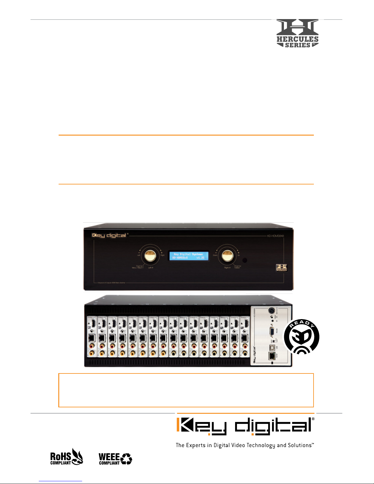
Key Digital® Hercules Series™ KD-HDMS8x8 is a HDMI Matrix Switcher capable of switching
up to 8 HDMI/DVI Video Sources/Inputs to 8 independent Zones/Outputs via HDMI and CAT5.
Features card slot architecture providing flexible Input/Output configurations.
KD-HDMS8X8
8 Inputs to 8 Outputs HDMI Matrix Switcher
Also Available in Configurable Models Below:
KD-HDMS1X15, 2X14, 3X13, 4X12, 5X11, 6X10, 7X9
KD-HDMS15X1, 14X2, 13X3, 12X4, 11X5, 10X6, 9X7
Set Up Guide
Page 2

Page 2
Table of Contents
About KD-HDMS8X8. . . . . . . . . . . . . . . . . . . . . . . . . . . . . . . . . . . . . . . . . . . . . . . . . . . . . . . . . 2
Connections, LCD and Button Map . . . . . . . . . . . . . . . . . . . . . . . . . . . . . . . . . . . . . . . . . . . . . . 3
Application Example . . . . . . . . . . . . . . . . . . . . . . . . . . . . . . . . . . . . . . . . . . . . . . . . . . . . . . . . . 5
Quick Setup Guide . . . . . . . . . . . . . . . . . . . . . . . . . . . . . . . . . . . . . . . . . . . . . . . . . . . . . . . . . . 6
IR Remote Command List . . . . . . . . . . . . . . . . . . . . . . . . . . . . . . . . . . . . . . . . . . . . . . . . . . . . .12
RS-232 Control Codes . . . . . . . . . . . . . . . . . . . . . . . . . . . . . . . . . . . . . . . . . . . . . . . . . . . . . . .12
Specifications . . . . . . . . . . . . . . . . . . . . . . . . . . . . . . . . . . . . . . . . . . . . . . . . . . . . . . . . . . . . . .16
Important Product Warnings & Safety Instructions . . . . . . . . . . . . . . . . . . . . . . . . . . . . . . . . . . .18
How to Contact Key Digital
®
. . . . . . . . . . . . . . . . . . . . . . . . . . . . . . . . . . . . . . . . . . . . . . . . . . . .19
Warranty Information . . . . . . . . . . . . . . . . . . . . . . . . . . . . . . . . . . . . . . . . . . . . . . . . . . . . . . . . .19
About KD-HDMS8X8
Description
» HDMI Matrix Switcher capable of switching up to 8 HDMI/DVI Video Sources/Inputs to 8
independent Zones/Outputs via HDMI and CAT5. Custom configurable to 1x15, 2x14, 3x13,
4x12, 5x11, 6x10, 7x9, 9x7, 10x6, 11x5, 12x4, 13x3, 14x2 and15x1 combinations.
Key Features
» Full switching of 3 independent matrixes: Video, Audio and Control
» Supports all SD, HD, and VESA (VGA, SVGA, XGA, WXGA, SXGA, UXGA) resolutions
up to 1080p (60Hz & 50Hz)
» SD & HD: 480i, 480p, 720p, 1080i, 1080p
» VESA / VGA (RGBHV): From 640x480p up to 1920x1200p
» Full support for HDMI
®
1.3a/b with HDCP, 3D Ready, 4K Resolution Support
» Supports lossless compressed digital audio (Dolby
®
TrueHD, Dolby® Digital Plus
and DTS
™
-HD Master Audio)
» Internal EDID Library features 8 default EDID configurations in addition to native
EDID data from any Output/Display
Key Benefits
» Transmits 1080p/60Hz resolution up to 140 ft, 1080p/24, 1080i, 720p and 480i/p resolutions
up to 270 ft, when used with KD-BBRX receiver Baluns
» Video, Audio, IR and RS-232 distribution via a single CAT5 cable
» Fully automatic CAT5 cable equalization, with optional manual calibration
» 16 active outputs (8 HDMI/DVI and 8 CAT5) enables flexible integration
» Full Audio control per output for volume, treble, bass, balance, and lip-sync from analog or
2ch. PCM HDMI digital sources
© 2010 Key Digital, Inc. All rights reserved.
Page 3
Page 3
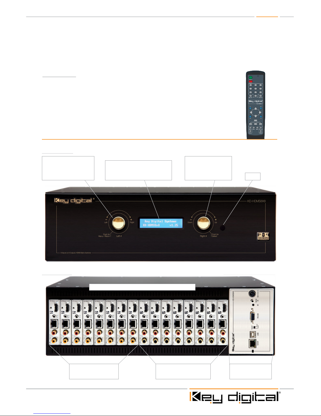
Connections, LEDs and Button Map
Front Panel
Main Control Panel
Please see p. 4 for
detailed description
Input Cards 1-8 (KD-HDUIC)
Please see p. 4 for
detailed description
Looking at the rear panel, card slots are numbered from left to right
Output Cards 1-8 (KD-HDUOC)
Please see p. 4 for
detailed description
LCD Screen
Displays Menu selections, Input and
Output information, system settings and
status information
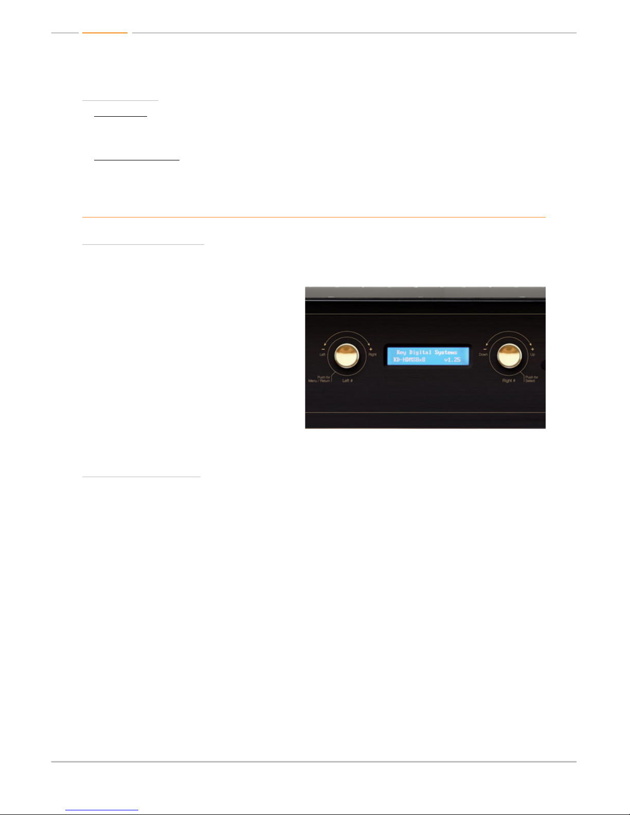
Right Selector
Use to access sub-menus
within the Main Menu.
(see pg.8 for complete
operating instructions)
Left Selector
Use to access Main Menu
and select sub-menu choices.
(see pg.7 for complete
operating instructions)
IR Eye
Rear Panel
» Serial IR, Optical IR, Front Panel Control, Discrete Remote Codes, RS-232 and TCP/IP.
Supports major control systems such as AMX
®
, Colorado vNet®, Control4®, Crestron®, RTI®,
Savant, Universal
®
, Xantech
®
Accessories
» External +12V/8.33A (100W) Power Supply – KD-PS12V8A
» IR Remote control with two batteries
» Operating Instructions
» HDMI Cable Clips (16)
» 6ft USB Data Cable
Page 4
Page 4
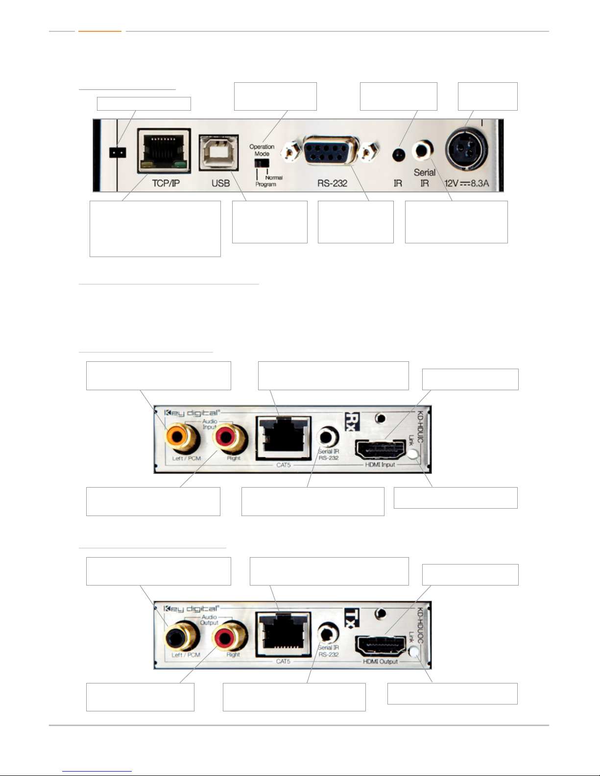
Main Control Panel
Rx Input Card (KD-HDUIC)
Tx Output Card (KD-HDUOC)
HDMI Input and Output Numbering
The KD-HDMS8x8 in its default configuration contains 8 Input cards and 8 Output cards. The Input
cards are addressed from 01-08, and the Output cards from 01-08.
Power
12V/8.33A (100W)
Power Supply
Rear IR Eye (Receiver)
Rear IR receiver for
remote control
Operation Mode Switch
Switch to “Program” mode
when updating firmware
For manufacturers use only
Serial IR
To Input from Control interface
for controlling unit via Serial IR
and IR routing
RS-232
The main RS-232/DB9
port for interfacing with
a control system.
USB
The USB port is for
software upgrades only.
It is not used for control
interface.
TCP/IP
This is the main TCP/IP port for interfacing
with control systems. It supports the same
control commands as the RS-232 port
and it can support TCP/IP to RS-232
conversion & routing and TCP/IP to serial
IR conversion & routing.
Serial IR / RS-232
Use the KD-HDMS as a Control Router for
devices integrated into your system
Serial IR / RS-232
Use the KD-HDMS as a Control Router for
devices integrated into your system
Left Analog Audio / PCM Audio Input
Supports Left channel Analog Audio Input or
use for Coaxial Digital Audio Input
Left Analog Audio / PCM Audio Output
Send Left channel Analog Audio or Coaxial
Digital Audio to your Display or other devices
CAT5 Input
Integrate a remote source by using the KD-BBTX
Transmit Balun to feed the CAT5 inputs
CAT5 Output
Use the KD-BBRX Receive Balun to carry Video,
Audio, and Control to your Display (or other) devices
Right Analog Audio Input
Supports Right channel Analog Audio Input
Right Analog Audio Output
Send Right channel Analog Audio
to your Receiver or other devices
Link LED
Indicates that input connection is stable
Link LED
Indicates that output connection is stable
HDMI Input
To Input source components
HDMI Output
To Output to Display
Page 5
Page 5
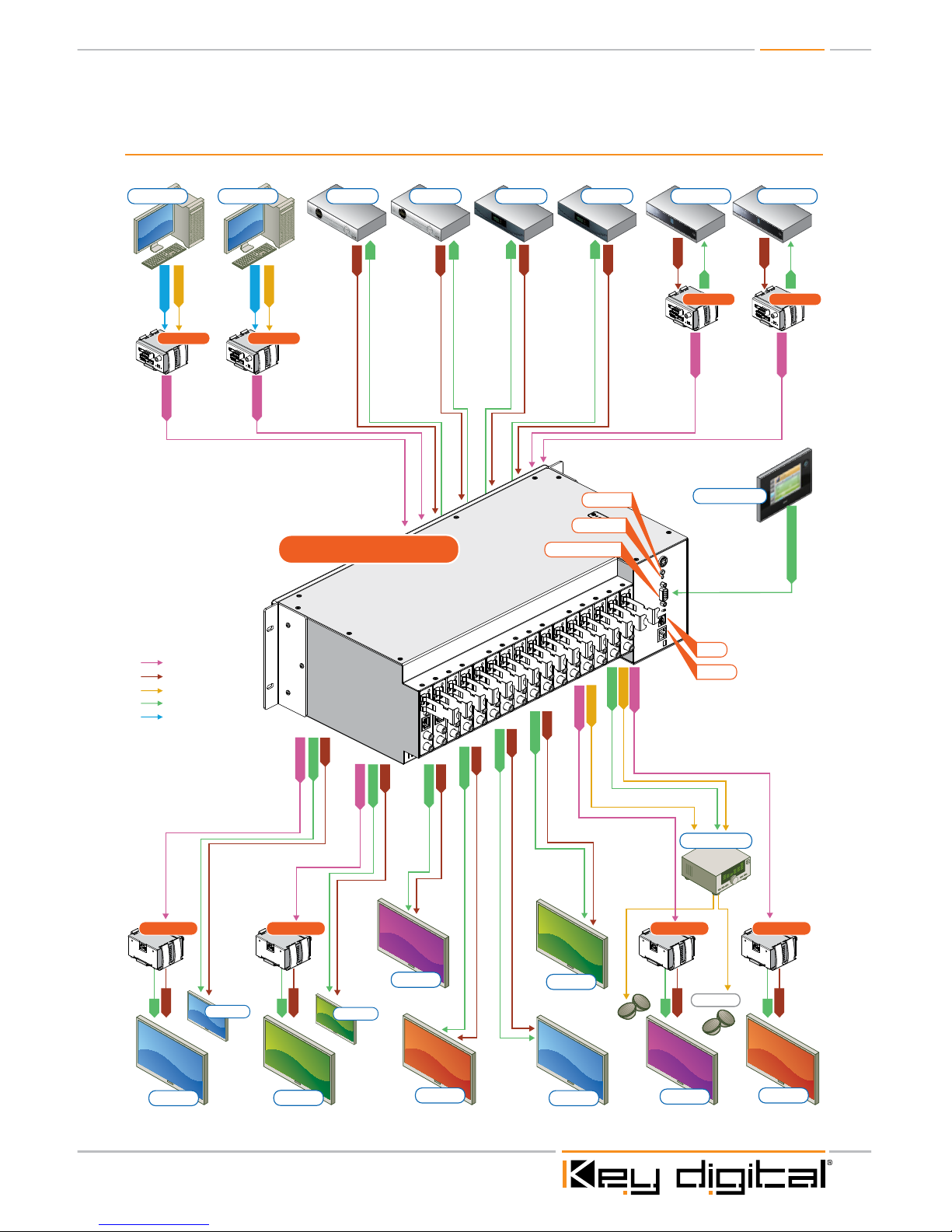
Application Example
DVI Video*
DVI Video*
L/R/PCM
L/R/PCM
CAT5/5e/6
L/R/PCM
CAT5/5e/6
CAT5/5e/6
CAT5/5e/6
CAT5/5e/6
L/R/PCM
CAT5/5e/6
CAT5/5e/6
CAT5/5e/6
Speakers
HDMI
HDMI
Blu-Ray
Satellite 1
Desktop PC Desktop PC
Display 8Display 4
Control System
DVI
HDMI/DVI
Audio
CAT5/6/7
IR/RS-232
IR
HDMI
HDMI
Blu-Ray
IR
IR
HDMI
IR
HDMI
IR
HDMI
IR
IR/RS-232
IR/RS-232 & TCP/IP
IR
HDMI
IR
HDMI
IR
HDMI
IR
IR/RS-232
IR/RS-232
HDMI
HDMI
IR/RS-232
HDMI
IR/RS-232
HDMI
IR/RS-232
HDMI
IR/RS-232
HDMI
Display 7
Display 3
Display 2
Display 5
Display 1 Display 6
Display 2a
Display 1a
(mirrored)
(mirrored)
Satellite 2 Cable 1 Cable 2
KD-BBTXKD-BBTX
KD-BBTX KD-BBTX
KD-BBRXKD-BBRXKD-BBRXKD-BBRX
KD-HDMS8X8
Transmits:
»1080p/60Hz resolution up to 140 ft
»1080p/24, 1080i, 720p and 480i/p resolutions up to 270 ft
» When used with KD-BBRX Receiver Baluns
RS232 Control
Serial IR
USB
TCP/IP
Optical IR
Surround Rcvr.
*To connect DVI use HDMI to DVI adapters
270’
180’
200’
150’
Page 6

Page 6
Quick Setup Guide
Initial Setup & Operation for HDMI via Front Panel
The KD-HDMS8x8 is set by default to HDMI Input. To change these default settings please see
“Initial Setup & Operation via CAT5 Baluns” section below.
1. Insert HDMI cables into card slots 1 through 16
» Slots 1-8 are labeled Rx, and are Input Card Slots 1-8.
» Slots 9-16 are labeled Tx, and are Output Card Slots 1-8.
» Connect your source components to the Input cards
» Connect your displays to the Output cards
» Power up all sources and displays
2. Establish an HDMI Handshake for Each Source
» Push the left selector to access the Main Menu choices
» Using the left selector, scroll to the “7-EDID Setup” Menu
» Press the right selector to navigate to the EDID sub-menus
» With the left selector, scroll to the Input source you wish to copy the EDID to
» Using the right selector, scroll to the HDMI or CAT5 Output you wish to establish an HDMI
handshake for, or select a Default EDID 01-08 from the EDID library (see pg.10)
» Press the right selector to set the Handshake for that combination
» Continue this procedure for all Inputs
» The EDID control and HDMI input set up is stored in a non-volatile memory back up and is
only required during initial set up or when a new display or source is added to the system.
» Establish a default handshake for ALL Inputs:
» Using the ‘7-EDID Setup’ Menu, select ‘ALL Inputs’ and scroll to the Output number
you wish to copy the EDID from (HDMI, CAT5 or a Default EDID setting) and press
the right selector
3. Switching via Front Panel
» Push the left selector to access the Main Menu choices
» Using the left selector, scroll to the “1-Video Switch” Menu
» Press the right selector to navigate to the Video Switch sub-menus
» Using the left selector, scroll to the Output you wish to select
» Using the right selector, scroll to the Input you wish to select
» Finally, press the right selector to make the switch
4. Sending your output via KD-BBRX CAT5 Receive Balun(s)
» Both HDMI and CAT5 Outputs are active on all Output Card Slots, therefore no configuration
is necessary to activate the CAT5 Output for each Tx Card Slot.
5. Sending your source via KD-BBTX CAT5 Transmit Balun(s)
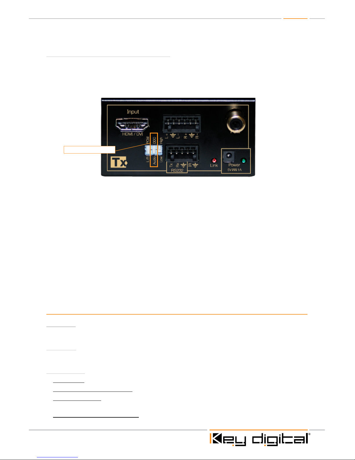
» Set dipswitch #2 of the KD-BBTX Balun to “DDC” in order to establish a proper HDMI
handshake
» Configure the appropriate Input Card Slot to activate its CAT5 input using the
“6-Video Input Setup”
Page 7
Page 7
Initial Setup & Operation via CAT5 Baluns
When using Key Digital Baluns (RX/TX) you must use the following procedure to correctly format
both the baluns and HDMS8x8 matrix switcher for correct operation.
» NOTE: Slots 1-8 are inputs, slots 9-16 are outputs.
» The KD-BBTX Dipswitch #2 MUST be set to the DDC position.
½ IMPORTANT: Make sure that you power up all baluns, sources and displays.
Confirm that you have an active connection on the Balun indicated by the solid
red “LINK” LED.
1. By default, the KD-HDMS8x8 is configured to accept a direct HDMI connection. When using
a KD-BBTX, you MUST change the input mode from HDMI to CAT5 to enable the switcher to
“see” the CAT5/Balun input. Select “6-Video Input Setup” from the main menu. Press the right
selector to navigate to the sub-menus. Using the left selector, scroll to the Input number you
wish to change. Using the right selector, scroll to select “CAT5” and press the right selector to
enter your choice.
2. Repeat procedure for any other input where a KD-BBTX is being used.
3. Once you have correctly configured the inputs to accept either HDMI and/or CAT5/Balun, you
need to establish the correct HDMI “handshake”.
4. See previous section on establishing an HDMI handshake.
Front Panel Menu Selection Controls:
Power On
½ The unit will power up with a push on either the left or right Selector.
Power Off
½ The unit will power off through IR, Remote, RS-232 or TCP/IP commands only.
Left Selector
½ Main Menu: To access the Main Menu push this selector once.
½ To Select Main Menu Options: Turn selector left or right to select Menu Options 1-9
½ Sub-Menu values: Turn this selector to scroll through the sub-menu selections. There will be left
and right sub-menu choices. Use the left selector to change left side options
½ To Go-Back to a previous menu: from whatever menu you are presently in you may return to the
previous menu by pressing this selector once. You will return to the menu you were previously in.
Dispwitch # - Select DDC
Page 8
Page 8
Right Selector
½ Sub-Menu: After selecting a specific Main Menu (1-9) option with the left selector, press the right
selector to select its Sub-Menu. You will be taken to the sub-menu for the main menu option you
had previously selected.
½ Sub-Menu values: Turn this selector to scroll through the sub-menu selections. Use the right
selector to change right side options. After a sub-menu choice has been made, push this
selector once to enter it. The display will blink to acknowledge your choice.
Menu Tree on LCD Display
Main Menu Selections:
Using the left selector, choose from the following Main Menu options;
1. Video Switch
2. Audio Switch
3. Volume Control
4. Audio Output Set Up
5. Audio Input Set Up
6. Video Input Set Up
7. EDID Set Up
8. TCP/IP Set Up
9. Factory Default
Using the right selector, push to enter the submenu for any of the selected main menu options above;
Sub-Menu Selections:
1. “Video Switch” options:
» Output 01–08
» All Outputs
Use the left selector to choose these.
For each Output number selected, ‘01-08’ and ‘All’, there are Input sub-menu choices;
» Input 01–08
Use the right selector to choose these and push to confirm your choice for both
Select an Output number with the left selector and then select an Input number you wish to feed
that output by turning the right selector. Push the right selector to select that combination. The
display will blink to acknowledge your choice. This will immediately switch your Output to the Input
selected.
2. “Audio Switch” options:
» Output 01-08 plus All Outputs
Use the left selector to choose these.
For each Output number selected, ’01-08’ and ‘All’, there are Audio sub-menu choices:
Page 9

Page 9
» HDMI
» External Analog
» External Digital
» CAT5
Use the right selector to choose these and push to confirm choice.
These correspond to which Audio signal type will be passed to the selected Output number from
your previously selected Input number.
3. “Volume Control Set Up” options:
» Output 01-08 plus All Outputs
Use the left selector to choose Output number desired.
Use the right selector to choose Volume level desired (00-99) and push to confirm choice.
Continue for all Outputs you wish to change
4. “Audio Output Set Up” options:
» Output 01-08 plus All Outputs
Use the left selector to choose these.
For each Output number selected, ’01-08’ and ‘All’, there are Audio Output sub-menu choices:
» Digital
» Analog
Use the right selector to choose these and push to confirm choice.
These correspond to the RCA connectors only and choose which format will be passed to the
Output selected.
5. “Audio Input Set Up” options:
» Input 01-08 plus All Inputs
Use the left selector to choose these.
For each Input selected, ’01-08’ and ‘All’, there are Audio Input sub-menu choices;
» Digital
» Analog
Use the right selector to choose these and push to confirm choice.
These correspond to the RCA connectors only and choose which format will be accepted by the
Input selected.
6. “Video Input Set Up” options:
» Input 01-08 plus All Inputs
Use the left selector to choose these.
For each Input selected, ‘01-08’ and ‘All’, there are Video Input type sub-menu choices:
» HDMI
» CAT5
Use the right selector to choose these and push to confirm choice.
Page 10

Page 10
7. “EDID Set Up” options:
» Input 01-08 plus All Inputs
Use the left selector to choose these.
For each Input selected, ’01-08’ and ‘All’, there are EDID Set Up sub-menu choices:
» HDMI Output 01 through 08
» CAT5 Output 01 through 08
» For each Input (source) selected with the left selector there is a choice to copy the EDID
information from either the HDMI or CAT5 connected Output (display) using the right
selector depending on which is connected. Both HDMI and CAT5 Inputs will receive the
copied EDID information.
» The Default choices (listed below) copy the EDID from a stored library of EDID configurations
to the selected Input card across both HDMI and CAT5 Inputs.
» Default EDID 1 – (1080i 2CH PCM)
» Default EDID 2 – (1080p 2CH PCM)
» Default EDID 3 – (1080i PCM, DTS/DOLBY. not including HD audio)
» Default EDID 4 – (1080p PCM, DTS/DOLBY. not including HD audio)
» Default EDID 5 – (1080i every audio including HD audio)
» Default EDID 6 – (1080p every audio including HD audio)
» Default EDID 7 – (3D 1080p 2CH PCM)
» Default EDID 8 – (3D 1080p every audio including HD audio)
Use the right selector to choose these and push to confirm choice. You will receive a “Completed”
message when successful, or a “Failed” message if unsuccessful.
8. “TCP / IP” options:
» IP address
» Sub net Mask
» Port
½ The default IP address is; ‘192.168.000.233’ This can be changed to accommodate your
particular configuration or controller.
½ The default Sub net mask is ‘255.255.255.000’ and may also be changed to accommodate your
particular configuration.
½ The default Port number is ‘23’
Select the TCP/IP option by pressing the right selector. Highlight the group of numbers you wish to
change by turning the left selector. Change the group of numbers using the right selector. Continue
this procedure until all numbers are chosen. Press the right selector to enter the changes. You may
then press the left selector to return to the previous menu if desired.
9. “Factory Default” options:
This option will return the unit to its Factory Default settings. Please see the list of default settings
below. When this menu option is chosen, you will be presented with a choice of EDID’s from the
default EDID library. Choose one of these default EDID’s (typically default 1-1080i 2Ch PCM) using
the left selector, then press the right selector to confirm. The unit will then reset to the default
configuration including the EDID you have chosen.
Page 11
Page 11
Factory Default Settings:
» Video = HDMI
» Input = 1
» Input Audio = Analog
» Output Audio = Analog
» Audio = HDMI
» Port = HDMI
» Output Volume = 50
» Output Bass = 12
» Output Middle = 12
» Output Treble = 12
» Output Balance = 20
» Output Delay = 00
» EDID = Choice of default EDID library 01-08
(see menu 7-EDID Set Up for a list of default EDID choices pg.10)
» TCP / IP = 192.168.0.233
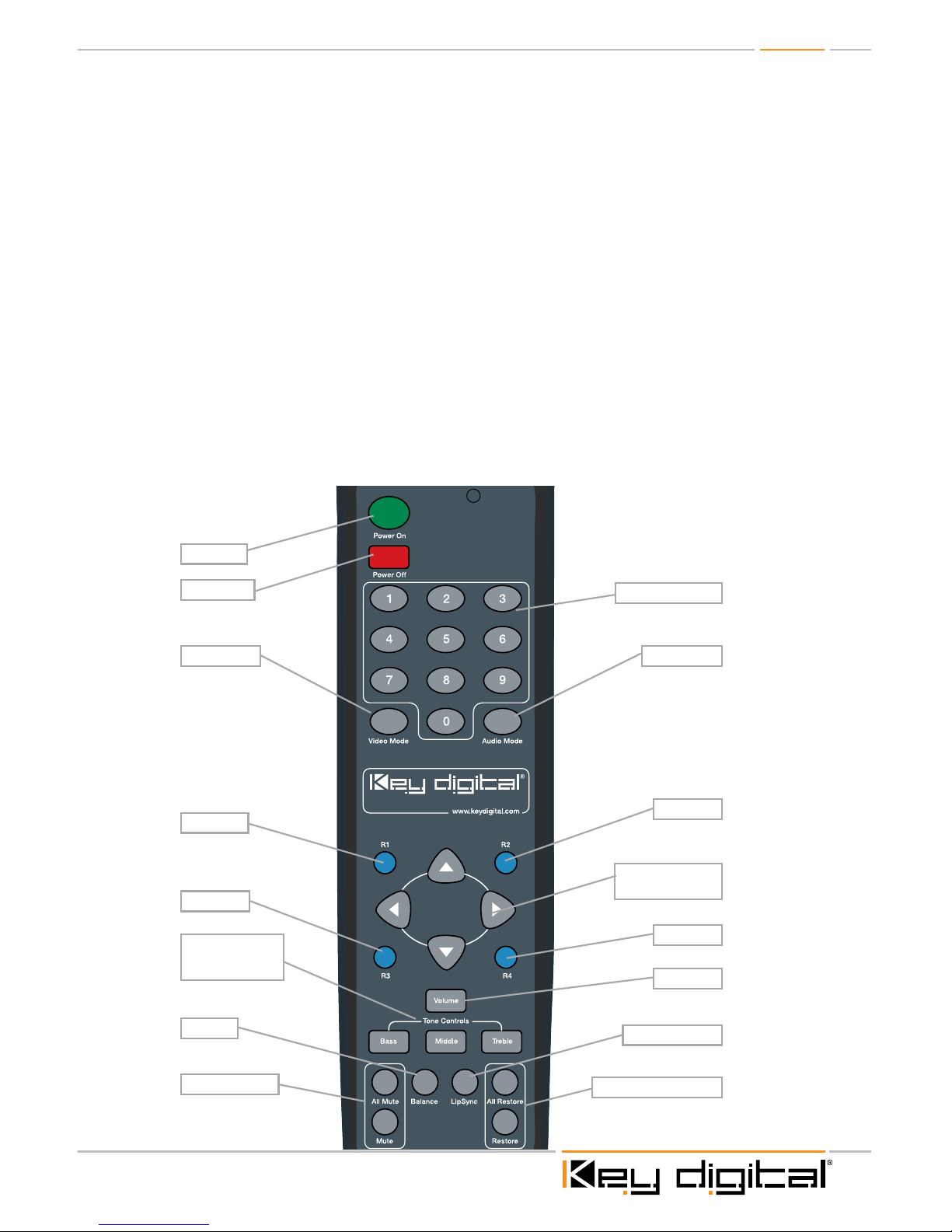
Power On
Power OFF
R1 Button
R2 Button
R3 Button
All Mute / Mute
Balance
Tone Controls:
Bass, Middle,
Treble
LipSync (Delay)
All Restore / Restore
Arrow Up, Down,
Left, Right
R4 Button
Volume
Numeric Keypad
Video Mode Audio Mode
Page 12
Page 12
KD-HDMS8x8 IR Remote Command List
Below are listed some of the most common remote commands. A complete list of all IR Remote
commands can be found at the Key Digital website www.keydigital.com
The following commands assume an 8x8 configuration.
» XX = Output Card Number (Range 01~08) [Outputs 1-8]
» YY = Input Card Number (Range 01~08) [Inputs 1-8]
» ZZ = Numeric Keypad Number (Range 00~99)
» Arrows = Up – Down – Left - Right
» Power On = “Power On”
» Power Off = “Power Off”
Switching Commands
Switch Input to Output:
» To Switch Output and Input cards by numeric keypad:
“R1 – XX – Video Mode – YY”
» Example: To switch Input 3 to Output 2 press; “R1–02–VideoMode–03
Switch Audio Output Source Type:
» To Switch Audio source of Output Card by numeric keypad:
“R1 – XX – Audio Mode – ZZ”
» Where ZZ is: 01 = HDMI
02 = RCA COAX SPDIF
03 = RCA ANALOG
04 = CAT5 AUDIO
» Example: To switch the audio source for output 2 to CAT5 press; “R1–02–AudioMode–04”
Front Panel Commands Using Remote
The Remote can be used to navigate through the front LCD display options.
½ Use the Left and Right Arrow keys to choose options normally made by rotating the Left Selector.
½ Use the Up and Down Arrow keys to choose options normally made by rotating the Right Selector.
½ Use the ‘R2’ button to enter choices normally made by pushing the Right Selector.
½ Use the ‘R4’ button to enter choices normally made by pushing the Left Selector.
RS-232 Control Codes
» Baud Rate: 57600
» Data Bits: 8
» Parity: None
» Stop Bits: 1
» Flow Control: None
» Carriage Return: Required
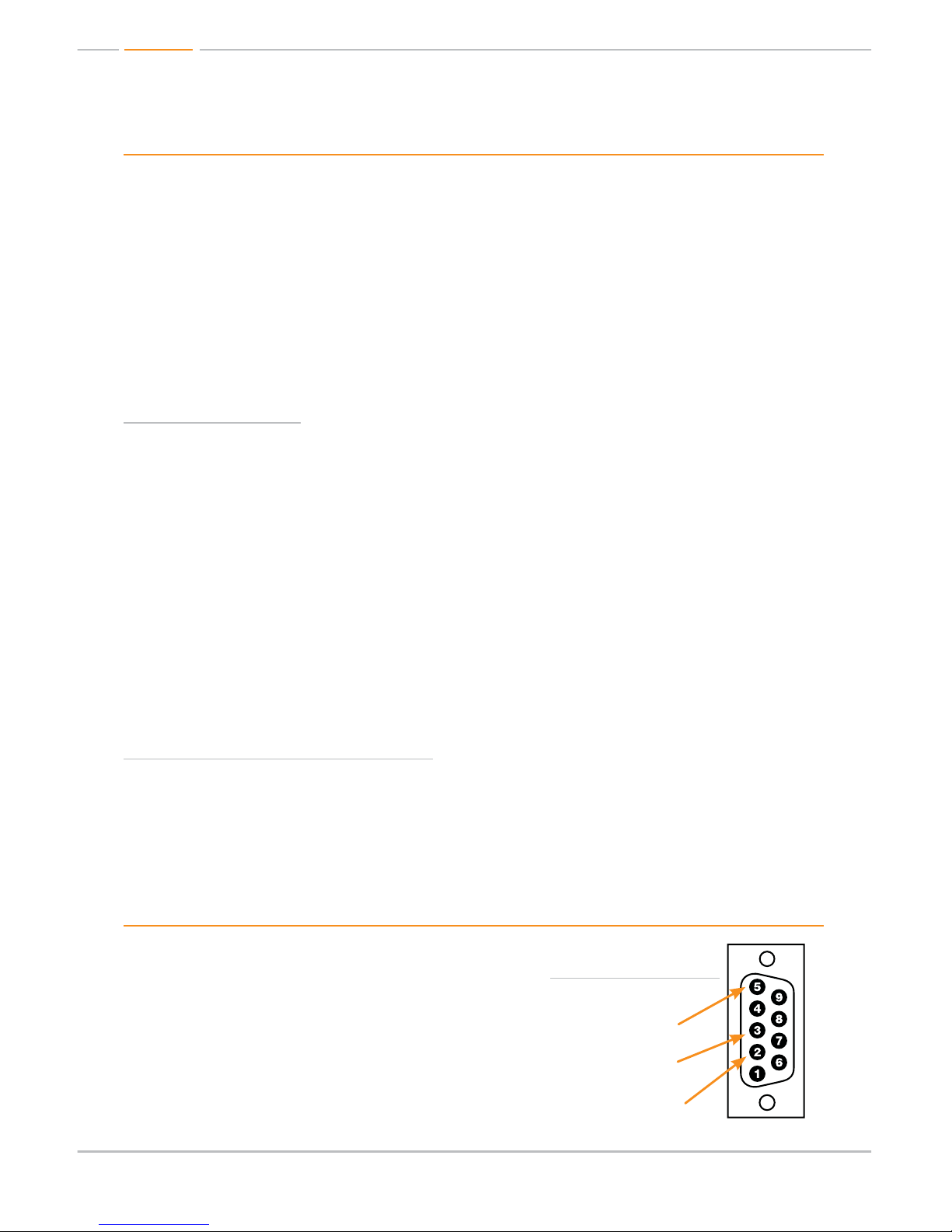
Pin 5 – Ground
Pin 3 – Receive
Pin 2 – Transmit
RS-232 cable pin out
Page 13
Page 13
Initial Setup & Operation via RS-232
A complete list of RS-232 Commands can be found at Key Digitals website: www.keydigital.com
1. Insert HDMI cables into card slots 1 through 8
» Slots 1-8 are labeled Rx, and are Input Card Slots.
» Slots 9-16 are labeled Tx, and are Output Card Slots.
2. If integrating your source via KD-BBTX CAT5 Transmit Balun(s)
» Set dipswitch # 2 of the KD-BBTX balun to “DDC” in order to establish a proper HDMI
handshake
» Configure the appropriate Input Card Slot to activate its CAT5 input using ‘SP I xx V y’ RS-
232 command.
» Where xx = Card Slot # of desired Input
» Where y = 1 or 2 (1 = HDMI, 2 = CAT5).
» Note: The default input configuration is “1” for HDMI.
3. If integrating your output via KD-BBRX CAT5 Receiver Balun(s)
» Both HDMI and CAT5 Outputs are active on Output Card Slots, therefore no configuration is
necessary to active the CAT5 Output for each Tx Card Slot.
4. Establish an HDMI Handshake for Each Source
» Copy EDID to Rx Card (xx) from Tx Card (yy) using ‘SP C EDID xx H/C/D yy’
» Where xx = Card Slot # of desired Input (01-08)
» Where H = HDMI, C = CAT5 or D = Default EDID Library (01-08)
» Where yy = Card Slot of # of desired Output (if H or C) (01-08)
» -------------------OR---------------------
» Where yy = Default EDID library # (01-08 ) (if D) *see Default EDID list pg.10
5. Matrix Switching via RS-232
» Use RS-232 command “SP Oxx SI yy”
» xx = Card Slot # of desired Output
» yy = Card Slot # of desired Input
½ NOTE: Spaces between RS-232 commands are shown for clarity only. Actual RS-232
commands do not need any spaces between characters.
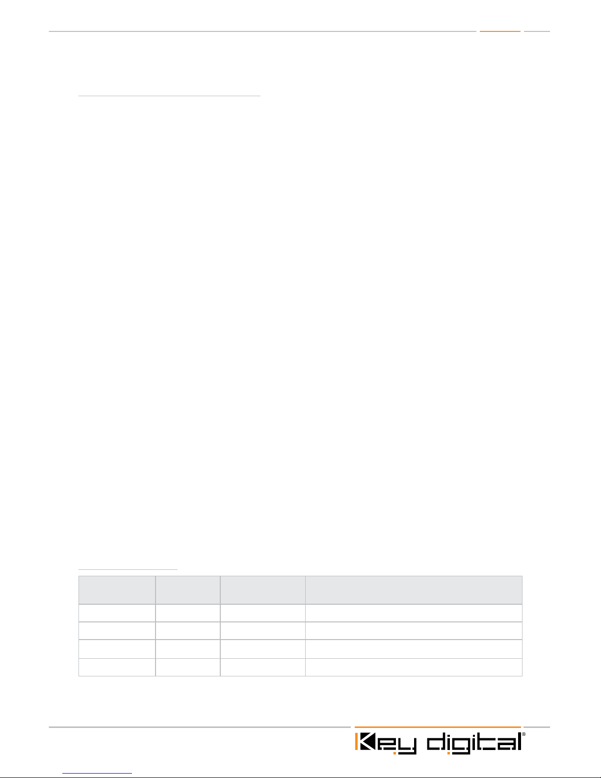
RS-232 Commands
Command
Name
Command Value Description
Status STA Gives full listing of Unit’s Status
Help H Gives full listing of RS-232 Commands
Power Off PF
Power On PN
Page 14
Page 14
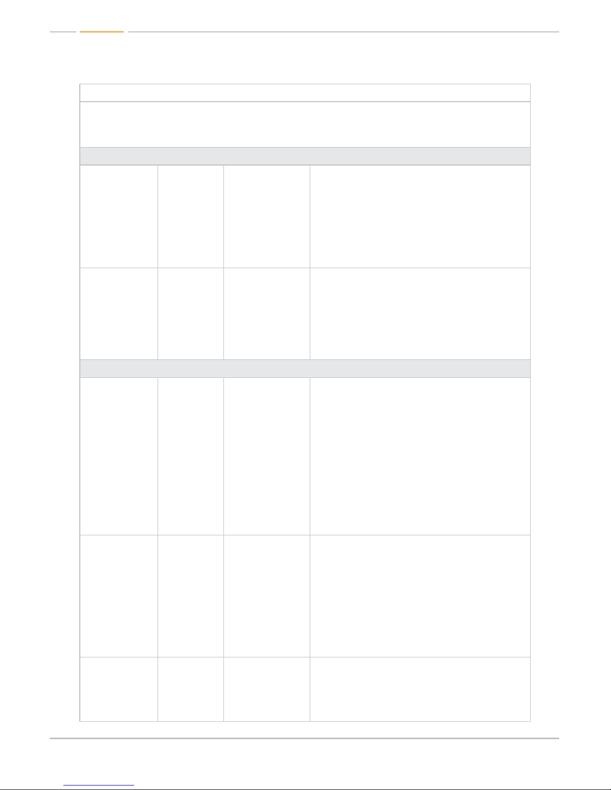
Input and Output numbers assume an 8x8 configuration.
Values for Commands:
Inputs: yy = 01-08 or A = All, U = Up, D = Down
Outputs: xx = 01-08 or A = All, U = Up. D = Down
System Input Setup Commands, xx = [01-08, A], (A=All):
Set Video Input
port
SPIxxVy xx = Input number
y = Input type
(1-HDMI, 2-CAT5)
To set which Video input type will be active by
specific input number.
Example: To set input 2 to HDMI, issue the
command; ‘SPI02V1’
Example: To set input 2 to CAT5 issue the
command: ‘SPI02V2’
Example: To set ALL inputs to HDMI issue the
command: ‘SPIAV1’
Set RCA Audio
Input type
SPIxxRCAy xx = Input number
y = RCA Audio
type (1-Analog,
2-Digital)
To set which Audio input type will be active.
Example: To set RCA input number 2 to Analog,
issue the command: ‘SPI02RCA1’
Example: To set ALL RCA inputs to Analog, issue
the command; ‘SPIARCA1’
Example: To set RCA input number 2 to Digital,
issue the command; ‘SPI02RCA2’
System Output Setup Commands, xx = [01-08, A], (A=All):
Set Output to
Video Input
SPOxxSIyy xx = Output
number (01-08)
yy = Input number
(01-08) or [U, D]
(U=Up, D=Down)
To switch Video Inputs to an Output.
Example: To switch Video at input 2, to output 6,
issue the command; ‘SPO06SI02’
Example: To step through each input going
up through the inputs, issue the command;
‘SPO01SI(U)’, each time this command is issued, the
selected output (1 in this case) will step through the
inputs in ascending order starting with the presently
selected input.To step through the inputs in
descending order from the presently selected input,
use ‘SPO01SI(D)’. (Do not add parentheses).
*NOTE: the above parameters are for an 8x8
configuration.
Set Output to
Audio Input
SPOxxSAyy xx = Output
number
yy = choice of
Audio Input type
desired, routed to
that Output.
(01-HDMI,
02-EXT PCM,
03- EXT ANALOG,
04-CAT5)
To set which Audio format is routed to which Output.
Example: To set output 6 to rout External Analog
Audio, issue the command;
‘SPO06SA03’
NOTE: This command must be issued in concert
with the above switching command for Video only.
Set Output
Volume
SPOxxAVyy xx = Output
number 01-08
or A (for All)
yy = Volume value
00-99
To set the Output Volume per Output number 01-08
or ALL outputs.
Example: To set Output 6 to 60, issue the
command; ‘SPO06AV60’ “
Page 15
Page 15
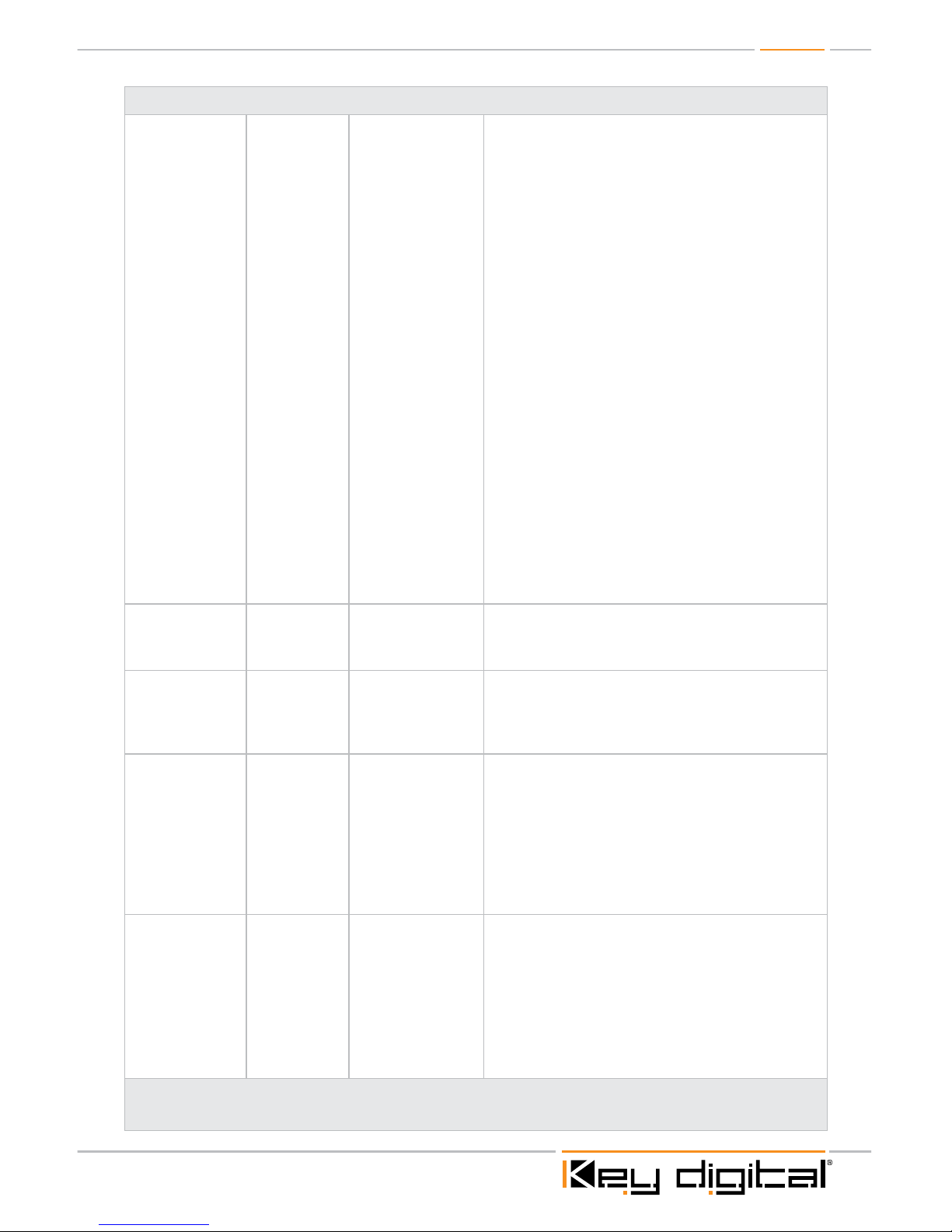
System Control Setup Commands:
Copy EDID
information to Rx
card slot, from
Tx card slot yy
via HDMI/CAT5/
or use Default
EDID library
SP C EDID
xx H/C/D yy
xx = Input card
number (01-08),
H = HDMI,
C = CAT5,
D = Default EDID
library
yy = (01-08),
01-08 Output card
number when ‘H’
/ ‘C’ is selected
–OR(01-08) Default
EDID library when
‘D’ is selected.
To copy the EDID information from an Output card
(display), to an Input card (source).
Example: To copy the EDID information from HDMI
Output 2, to HDMI Input 4, issue the command;
‘SPCEDID04H02’
Example: To copy the EDID information from CAT5
Output 2, to HDMI Input 4, issue the command;
‘SPCEDID04C02’
Example: To load ‘DEFAULT2’ EDID library for Input
card 3, issue the command; ‘SPCEDID03D02’
Below are the Default EDID library choices when
selecting ‘D’ as a variable:
01 = DEFAULT1 (1080i 2CH PCM)
02 = DEFAULT2 (1080p 2CH PCM)
03 = DEFAULT3 (1080i PCM, DTS/DOLBY.
not including HD audio)
04 = DEFAULT4 (1080p PCM, DTS/DOLBY.
not including HD audio)
05 = DEFAULT5 (1080i every audio
including HD audio)
06 = DEFAULT6 (1080p every audio
including HD audio)
07 = DEFAULT7 (3D 1080p 2CH PCM)
08 = DEFAULT8 (3D 1080p every audio
including HD audio)
Front Panel
Buttons
SPCFBE/D E = Enabled /
D = Disabled
To Enable or Disable the front panel buttons.
Example: To Disable the front panel buttons, issue
the command; ’SPCFBD’
Adjust EQ for
CAT5 length
per Input
SPCCAT5IC
xxyy
xx = Input number
yy = EQ Value
0-40 (default is 20)
To adjust CAT5 Input EQ for fine tuning Video signal
if necessary
Example: To adjust CAT5 Input 6 EQ to value 30,
issue the command: ‘SPCCAT5IC0630’
Configure CAT5
Output to either
DDC or PCM
Audio
SPCCAT5OC
hhhh
‘hhhh’ = hex value
for Input or Output
numbers selected.
To set CAT5 Output to either DDC (Data Display
Channel) or PCM Audio.
Default or unselected will be DDC, selected Inputs/
Outputs will be PCM Audio.
Binary value 0 = DDC, 1 = PCM Audio
Example: To set the CAT5 output of outputs 1 and
6 to PCM, issue the command; ‘SPCCAT5OC2100’,
all other outputs will remain DDC
Reset to Factory
Defaults
SPCDFxx xx = 01-08 and
represents the
default EDID
choice desired
after reset. (See
menu 7-EDID
Set Up options
for default EDID
choices)
To reset factory default settings by type.
Example: To reset to 1080p HD Audio EDID, issue
the command; ‘SPCDF06’
Please see our website product page for a complete list of all RS-232 commands:
www.keydigital.com
Page 16

Page 16
Specifications
» Video Input Interface (HDMI Input Card): Has both HDMI and CAT5 (RJ45) Inputs, only 1
of these Inputs can be selected per Input card
» Supports HDMI 1.3a and 3D Feature of HDMI1.4
» CAT5(RJ45) works only with KD-BBTX Balun and HDMI with KD-CATHD(TX) Baluns.
» Video Output Interface (HDMI Output Card):
» Features both HDMI and CAT5(RJ45) outputs, and provides both simultaneously.
» Supports HDMI 1.3a and 3D Ready, 4K Resolution Support features of HDMI1.4
» CAT5(RJ45) works only with KD-BBRX Balun and HDMI with KD-CATHD(RX) Baluns..
» Audio Input Interface (HDMI Input Card):
» Supports both PCM and Analog Stereo Audio inputs. The PCM Input shares the same
RCA connector as Left Analog stereo and only one of these audio inputs / formats can
be selected at a time.
» The Analog Stereo Audio input is processed at 48kHz sampling rate.
» Audio Output Interface (HDMI Output Card):
» Supports both PCM and Analog Stereo Audio Outputs. The PCM Output shares the
same RCA connector as Left Analog stereo and only one of these audio outputs / format
types can be selected at a time.
» 1. When the PCM Output is selected and its source is from the external PCM Input, PCM
(at 48 kHz) will be in bypass mode to pass Dolby Digital, DTS, or 2Ch PCM and will be
without audio control.
» 2. The Analog Stereo Audio Input is processed (at 48 kHz) and will be converted to
digital audio at the PCM Output if desired. Full audio control will be available in this case.
» 3. When HD Audio (HD-Dolby Digital, HD-DTS etc.) or multi-channel PCM is carried
by HDMI, it will be muted at the PCM Output if HDMI is selected as the audio input
source.
» Control Interface (HDMI Input/Output Card):
» Supports both RS-232(up to 115200bps) and Serial IR and shares the same stereo mini-
jack. Only one control protocol can be selected through control port settings.
» RS-232 and Serial IR support bi-directional paths. Output signal level is +5V TTL and
has +/-12V tolerance.
» Control Interface (Power Board):
» Supports one RS-232(DB9), one TCP/IP(RJ45), one USB(B Type) for service only
(software upgrade), one Serial IR and one IR Eye.
» RS-232 baud rate for control of unit is fixed at 57,600bps.
» RS-232 and TCP/IP share same control commands.
» Serial IR supports bi-directional path. Output signal level is +5V TTL with +/-12V
tolerance.
» IR Eye is only for Remote IR receiving sensor.
Page 17

Page 17
» Front Panel Interface:
» 2 row LCD Display, two rotary knobs(left and right) with push-to-select action to control
menu choices for front panel control, and IR Eye
» IR Eye is only for Remote IR receiving sensor.
Technical:
» Regulation: RoHS, WEEE
» Input (Each): 1 HDMI; 1 CAT5 on RJ-45 connector; Left and Right Stereo on two RCA, or
one SPDIF digital audio on Left RCA connector; 1 wired IR or RS-232 on 3.5 mm stereo jack
connector per input
» Output (Each): 1 HDMI; 1 CAT5 on RJ-45 connector; Left and Right Stereo on two RCA,
or one SPDIF digital audio on Left RCA connector; 1 wired IR or RS-232 on 3.5 mm stereo
jack connector per output
» Configuration: 8 input sections and 8 output sections in standard configuration
» Bandwidth: TMDS bandwidth 10.2 Gb/s
» Control: Front panel push buttons and LCD display; Infrared IR front; RS-232 Tx and Rx
lines; Full bi-directional operation
» Video/Audio Matrix Switching: Full Matrix switching of 2 independent matrixes:
Video & Audio
» RS-232 Control Matrix: RS-232 input/output can independently control the system
or input/output through attached KD-BBTX or KD-BBRX Balun. Full bi-directional RS-232.
» Wired IR Control Matrix: Each input/output section wired IR and unit wired IR can be
switched into matrix in bi-directional operation to any of the inputs/outputs
» EQ adjustment: On Rx Balun or CAT5 Input. Precise auto-adjustment, distance
measurement
» Compliance with HDMI
®
Standards: Supports HDMI® 1.4 features (3D Ready,
4K Resolution Support), HDMI
®
1.3a/b, HDMI 1.2, HDMI 1.1, DVI 1.1, and HDCP
» Link and Range: Single Link Range: 1080p/60, 1920x1200 max. UTP 140 feet. STP 160 feet.
For 1080i/60; 720p; 1080p/24 UTP 270 feet, STP 280 feet
» Lossless Compressed Digital Audio: Support lossless compressed digital audio
(Dolby
®
TrueHD, Dolby® Digital Plus and DTS™-HD Master Audio)
» DDC Signal (Data): Input DDC Signal: 5 Volts p-p (TTL)
» HDMI Video/Audio Signal: Input Video Signal: 1.2 Volts p-p
» HDMI Connector: Type A, 19 Pin Female
» RJ45 Connector: Link Connector: RJ-45 Shielded
» I2C Communication: EDID and HDCP Bi-Directional Transparency from Display to Source
» EDID Control: Each input EDID is either a choice of any of the active zone displays
connected via HDMI or CAT5 to the outputs or from internal library of 8 Default EDIDs
» RS-232: RS-232 Tx and Rx line active and bi-directional up to 115,200 baud rate
» Wired IR: IR line modulated or not modulated, active and bi-directional 0-5V TTL
or -10to +10V.
» Power: External Power Supply. 12V/8.33A
Page 18
Page 18
General:
» Regulation: RoHS, WEEE
» Rack Mount: 3RU, Full Rack Width (rack ears included)
» Enclosure: Black Metal
» Product Dimensions: L = 17.5” W = 9.25” H = 5.25”
» Shipping Carton Dimensions: L = 20” W = 12.4” H = 8”
» Product Weight: 14 lb.
» Shipping Weight: 24 lb.
» Accessories: IR Remote Control, UL Certified Power Supply - 12V / 8.33A, 16 HDMI Cable
Clips, 6ft USB Data Cable
Important Product Warnings:
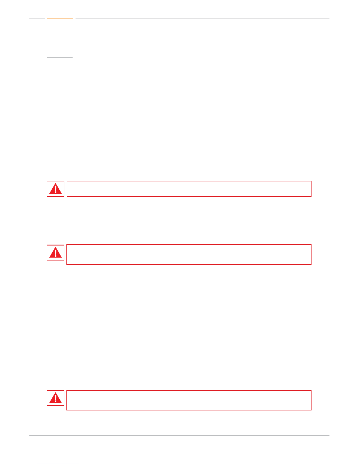
1. Connect all cables before providing power to the unit.
2. Test for proper operation before securing unit behind walls or in hard to access spaces.
3. If installing the unit into wall or mounting bracket into sheet-rock, provide proper screw support
with bolts or sheet-rock anchors.
Safety Instructions.
Please be sure to follow these instructions for safe operation of your unit.
1. Read and follow all instructions.
2. Heed all warnings.
3. Do not use this device near water.
4. Clean only with dry cloth.
5. Install in accordance with the manufacturer’s instructions.
6. Do not install near any heat sources such as radiators, heat registers, stoves, or other
apparatus (including amplifiers) that produce heat.
7. Only use attachments/accessories specified by the manufacturer.
8. Refer all servicing to qualified service personnel. Servicing is required when the device has
been damaged in any way including:
» Damage to the power supply or power plug
» Exposure to rain or moisture
You MUST use the Power Supply provided with your unit or you VOID
the Key Digital
®
Warranty and risk damage to your unit and associated equipment.
Page 19

Page 19
How to Contact Key Digital
®
System Design Group (SDG)
For system design questions please contact us at:
½ Phone: 914-667-9700
½ E-mail: [email protected]
Technical Support
For technical questions about using Key Digital® products, please contact us at:
½ Phone: 914-667-9700
½ E-mail: [email protected]
Repairs and Warranty Service
Should your product require warranty service or repair, please obtain a Key Digital® Return Material
Authorization (RMA) number by contacting us at:
½ Phone: 914-667-9700
½ E-mail: [email protected]
Feedback
Please email any comments/questions about the manual to:
½ E-mail: [email protected]
Warranty Information
All Key Digital® products are built to high manufacturing standards and should provide years of
trouble-free operation. They are backed by a limited two-year parts and labor warranty.
Page 20

521 East 3rd Street, Mount Vernon, NY 10553
Phone :: 914.667.9700 Fax :: 914.668.8666
Web :: www.keydigital.com
Key Digital®, led by digital video pioneer Mike Tsinberg,
develops and manufactures high quality, cutting-edge
technology solutions for virtually all applications where
high quality video imaging is important. Key Digital
®
is at the forefront of the video industry for Home
Theater Retailers, Custom Installers, System Integrators,
Broadcasters, Manufacturers, and Consumers.
Rev 0 – Dec. 2010
 Loading...