

Key Digital KD-HD4x4, KD-HD6x6, KD-HD8x8Lite Setup Manual
The Experts in Digital Video Technology and Solutions
™
Key Digital®, led by digital video pioneer Mike Tsinberg,
develops and manufactures high quality, cutting-edge
technology solutions for virtually all applications where
high quality video imaging is important. Key Digital
®
is at the forefront of the video industry for Home Theater
Retailers, Custom Installers, System Integrators,
Broadcasters, Manufacturers, and Consumers.
Key Digital® Systems :: 521 East 3rd Street :: Mount Vernon, NY 10553
Phone : 914.667.9700 Fax : 914.668.8666 Web : www.keydigital.com
Rev 0 – Nov 2013
HDBT/HDMI via Single CAT5e/6 Matrix Switcher.
Includes KD-CATHD250POHRx Receiver Extenders.
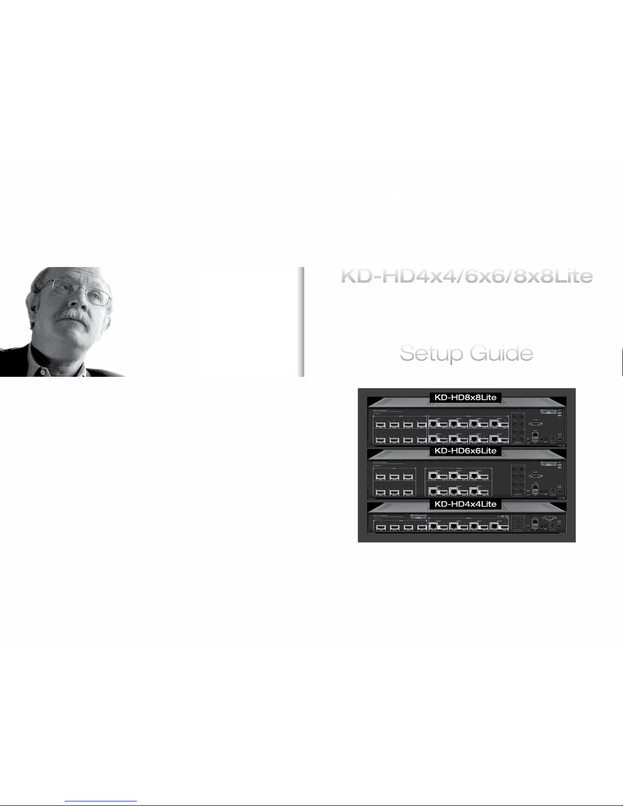
KD-HD4x4/6x6/8x8Lite
Setup Guide
KD-HD8x8Lite
KD-HD6x6Lite
KD-HD4x4Lite
4 1
Table of Contents
About KD-HD4x4/6x6/8x8Lite .................................................. 1
Connections, Buttons and LEDs ................................................ 2
Application Example ......................................................... 3
Quick Setup Guide .......................................................... 4
KD-CATHD250POHRx Baluns.................................................. 4
Extending and Routing Control Signals ........................................... 5
Settings................................................................... 6
Remote Control ............................................................. 7
RS-232 Commands ......................................................... 8
Firmware Upgrade Procedure ................................................. 13
Audio Return Channel ....................................................... 15
Specications ............................................................. 16
Important Product Warnings & Safety Instructions: ................................. 17
How to Contact Key Digital
®
.................................................. 18
Warranty Information ........................................................18
About KD-HD4x4/6x6/8x8Lite
Key Digital® Digital IQ Series™ KD-HD4x4/6x6/8x8Lite are HDBaseT® Lite HDMI Matrix
Switchers capable of switching up to 8 HDMI Video Sources/Inputs to up to 8 Independent
Zones/Outputs via Single CAT5e/6.
Advanced HDMI
®
Features
› 3D – Capability to pass 3D stereoscopic signal formats
› 4K – 4096x2160/24 video resolution support for commercial applications such as Digital Movie
Theaters, CAD, Post Production, Graphics, etc.
› Audio Return Channel (ARC) – Allows audio to be returned from display back to HDMI source
for amplication and display
Key Features
› Features both HDMI and CAT5e/6 (RJ45) outputs, both are active simultaneously
› Transmits 1080p/60, 1080p/24, 1080i, 720p signals up to 210 ft. Transmits 4k/Ultra HD signals
up to 120 ft. when used with KD-CATHD250POHRx Receiver extenders and approved Key Digital
CAT5e/6 cabling. Compatible with third-party CAT5e/6 with lesser distance performance.
› Supports all SD, HD, and VESA resolutions up to 1080p (60Hz & 50Hz), 4K/Ultra HD & ARC
› Internal EDID Library features 12 default EDID congurations, in addition to Native EDID data for
any Output/Display
› Full Buffer
™
Technology – Full matrix buffering of HDCP and EDID for seamless switching and
viewing of any source/input to any display/output, regardless of multiple output viewing relation
› TMDS re-clocking –
support long HDMI or CAT5e/6 connections and daisy chain congurations
› RJ45 outputs utilize the HDBaseT
®
format
› Control routing enables bi-directional IR and RS-232 control signal extension
› Serial IR, Optical IR, Front Panel & RS-232 control. Supports major control systems such as
Compass Control
®
, AMX®, Control4®, Crestron®, RTI®, Universal®.
› Includes 4/6/8 KD-CATHD250POHRx Receiver Extenders
› Fully automatic CAT5e/6 cable equalization
› 8/12/16 active outputs (4/6/8 HDMI/DVI and 4/6/8 CAT5e/6) enable exible integration
› Supports switching of lossless compressed digital audio:
» Dolby
®
TrueHD, Dolby® Digital Plus and DTS™-HD Master Audio
Accessories
› 4/6/8/ KD-CATHD250POHRx Receiver Extenders
› Two external power supplies. Matrix: +6V/11.6A
(70W); KD-CATHD250POHRx:+12V/6A (70W)
› IR Remote control; HDMI Cable Clips (8/12/16); 6 ft.
USB Data Cable
Rack Mounting:
› Secure the rack ears to each side of the
KD-HD4x4/6x6/8x8Lite
with the supplied hardware,
then, fasten the unit to the rack rails with the included machine screws.
Slide Clip on
to Screw
Loosen Screw
Secure Screw
Insert Key Digital
®
HDMI® Cable
Fasten HDMI Cable to Clip
with Cable Tie
1
2
3
4
5
© 2013 Key Digital, Inc. All rights reserved.
2 3
Connections, Buttons and LEDs
Rear Panel Connections:
HDMI Inputs & LEDs
I/O
Ports
HDMI & CAT5e/5 Outputs & LEDs
Power
Operation
Mode
RS-232 Port
Power POHSerial IRIR EyeUSB
TCP/IP
Connections
› HDMI Inputs: Located on the left side of the
back panel. The Inputs have a blue LED that
will illuminate when a source is connected and
synced.
› HDMI & CAT5e/6 Outputs: Located in the
middle of the back panel. The Outputs have
a blue LED that will illuminate when a output
device is connected and synced.
› The RS-232, Serial IR, Optical IR Sensor,
Operation Mode Switch, TCP/IP, USB and
Power connections are located on the right
side of the back panel.
› I/O Ports: Located to the right of the Outputs.
› The Operation Mode switch is used to update the unit’s rmware, which is done via RS-232,
USB or TCP/IP. The rmware version as well as all RS-232 commands is available through the
RS-232 command ‘H’. A detailed list of RS-232 commands is available later in this guide.
› If newer rmware is made available, complete updating instructions will be included with it. Check
the Key Digital website for any rmware updates.
Front Panel Buttons and LEDs
IR Eye
Input LEDs
Output Select Buttons
› There are 4/6/8 Output buttons along the front panel.
› Pressing an output button will select the next HDMI input.
› A blue LED will indicate which Input has been selected for each Output.
› There is also an Optical IR window located on the right side of the front panel for IR remote
control signals.
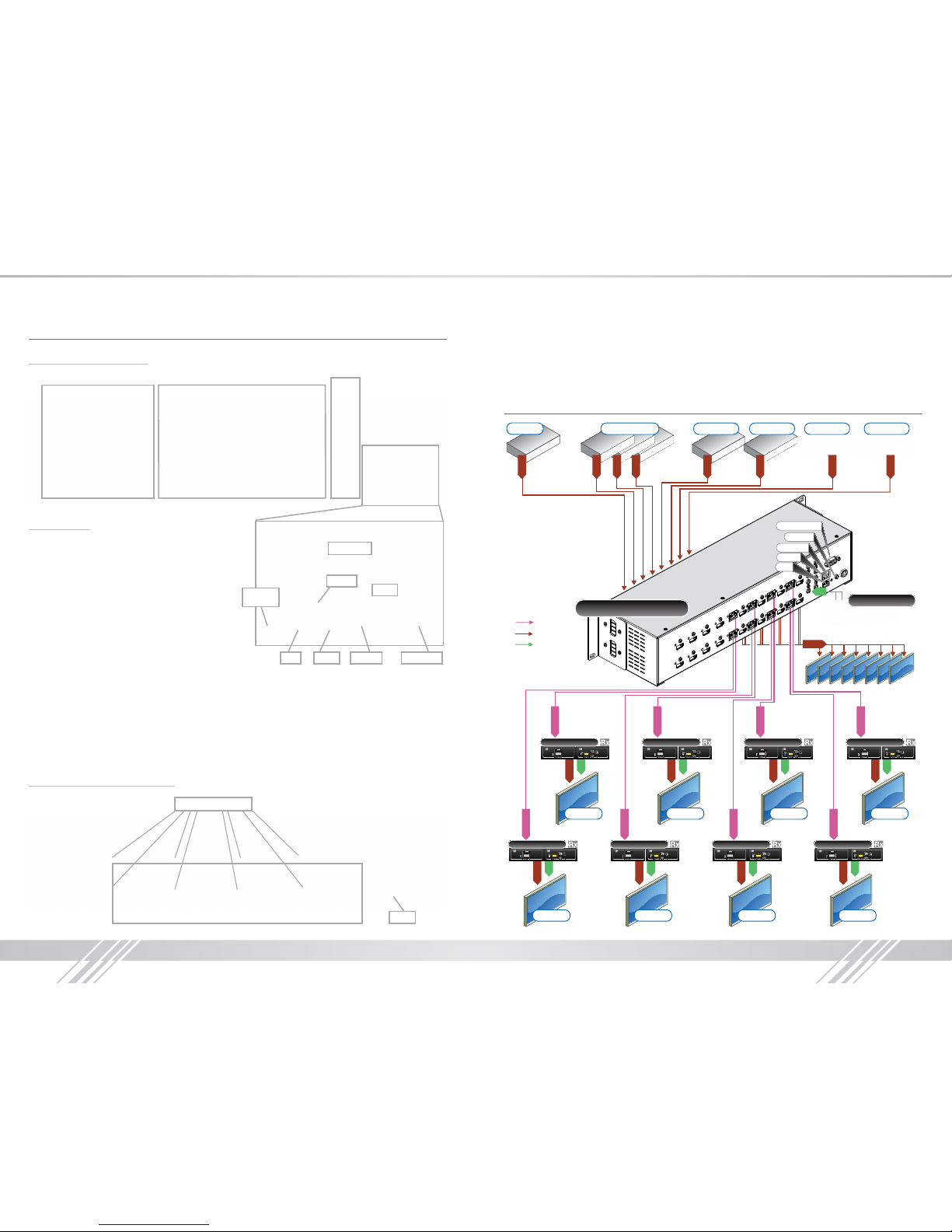
Application Example
CAT5e/6
CAT5e/6
CAT5e/6
CAT5e/6
CAT5e/6
CAT5e/6
CAT5e/6
CAT5e/6
Blu-Ray
HDMI
Satellite STB DVD-HD PS3 AppleTVCable Boxes 1-3
HDMI
HDMI
HDMI
HDMI
HDMI
HDMI
HDMI
HDMI
KD-HD8x8Lite
HDMI
Single CAT5e/6
IR
RS232 Control
Serial IR
Optical IR
USB
TCP/IP
IR
Display 5
210 ft.
HDMI
IR
KD-CATHD250POH
Display 6
210 ft.
HDMI
IR
KD-CATHD250POH
Display 7
210 ft.
HDMI
IR
KD-CATHD250POH
Display 8
210 ft.
HDMI
IR
KD-CATHD250POH
Display 1
210 ft.
HDMI
IR
KD-CATHD250POH
Display 2
210 ft.
HDMI
IR
KD-CATHD250POH
Display 3
210 ft.
HDMI
IR
KD-CATHD250POH
Display 4
210 ft.
HDMI
IR
KD-CATHD250POH
KD-MC2500
Master Controller
Mirrored HDMI
4 5
Quick Setup Guide
1. Begin with the KD-HD4x4/6x6/8x8Lite and all input/output devices turned off and power
cables removed.
2. Connect HDMI sources to the appropriate input ports on the KD-HD4x4/6x6/8x8Lite.
3. Connect CAT5e/6 outputs to the KD-CATHD250POHRx extenders via CAT5e/6 cables, then
connect the extenders to the output devices (display, projector, AV Receiver, etc).
4. Connect HDMI outputs to the appropriate output device (outputs will mirror CAT5e/6).
5. Connect both power supplies (one for the Matrix and one for the POH Extenders) to the KDHD4x4/6x6/8x8Lite and all other input and output devices and turn them on.
6. Operate the KD-HD4x4/6x6/8x8Lite switcher via front panel buttons, IR Remote, Serial IR or
RS-232 control.
Operation:
After performing the setup above, the unit is ready for operation.
There are several options for controlling the unit. Commands can be issued via IR remote control,
RS-232, TCP/IP or by using the front panel buttons. Note that the advanced commands are
available only via the RS-232 protocol.
KD-CATHD250POHRx Baluns
If you will be utilizing the KD-CATHD250POHRx extender, please follow this procedure.
› One CAT5e/6 UTP or STP cable needs to be used.
› Use the shortest possible HDMI cable when connecting the Extender to the Display. Key Digital
recommends cables 6 ft. or shorter for optimum performance.
› Ensure the CAT cable is run directly from the switcher to the Extender.
› Do not use patch panels, punch downs, keystones, couplers, wall plates, etc..
› Key Digital recommends the use of CAT5e/6 STP cable with shielded RJ45 connectors
for optimum performance and distances from your Extender.
Extending and Routing Control Signals
› The KD-HD4x4/6x6/8x8Lite feature powerful and useful control routing features. The switchers
have the ability to matrix control signals just like they can audio and video signals.
› KD-HD4x4/6x6/8x8Lite can consolidate incoming IR/RS-232 signals to control any display/output
connected via CAT5/6 or via HDMI (control signal extension via HDMI only available with Key
Digital Commercial HiFi ProS cables).
› KD-HD4x4/6x6/8x8Lite can consolidate incoming IR/RS-232 signals to control any source/input
connected via HDMI, with Key Digital’s Commercial HiFi ProS cables.
› IR and RS-232 control signals are bi-directional, and may ow from the matrix to the zone or from
the zone to the matrix.
› The default signal path for control signals is to route IR control signals from Expansion I/O Port 1
to RJ45 output 1…Expansion I/O Port 8 to RJ45 Output 8 (the path and control signal type can
be manipulated by using the desired RS-232 command).
› When connecting the IR Emitter to the device you wish to control, make sure to nd the IRreceiver
area on the device
Control Signal Extension from External I/O Ports:
The default setting for control signal extension is to route IR signals from Expansion I/O Port 1 to
RJ45 output 1…Expansion I/O Port 8 to RJ45 Output 8 (the path and control signal type can be
manipulated by using the desired RS-232 command). When routing control signals to/from an
HDMI input/output, Key Digital’s HiFiProS cable must be used.
› Point-to-Point control routing is established by using commands containing “IRR” or “RSS”.
› Point-to-Many control routing is established by using commands containing “IR” or “RS”.
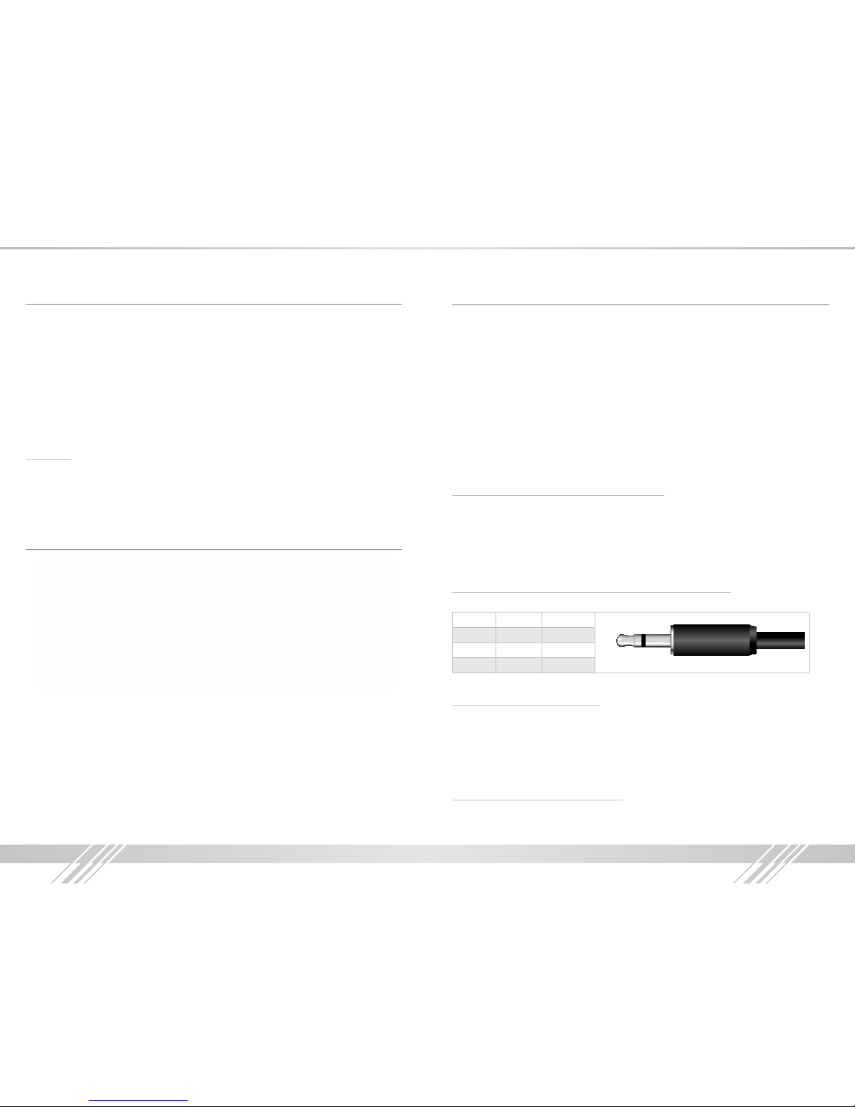
Extension I/O and Digital Audio Output (ARC) Port Conguration
Supports IR or RS-232 routing or ARC output. See chart below for 3.5mm jack conguration:
Tip Ring
IR TX or RX None
RS232 TxD RxD
ARC NONE ARC OUT
Note: If ARC is enabled, IR and RS-232 signal routing will be disabled.
Point-to-Point IR Control Routing:
› To congure the path of IR control signals from an External I/O Port to an RJ45 output, use the
command “SPOC xx IRR 1 S yy”. xx=IR destination, yy=IR source
› To congure the path of IR control signals from an External I/O Port to an HDMI output, use the
command “SPOH xx IRR 1 S yy”. xx=IR destination, yy=IR source
› To congure the path of IR control signals from an External I/O Port to an HDMI input, use the
command “SPI xx IRR 1 S yy”. xx=IR destination, yy=IR source
Point-to-Point RS-232 Control Routing:
› To congure the path of RS-232 control signals from an External I/O Port to an RJ45 output, use
the command “SPOC xx RSS 1 S yy”. xx=RS-232 destination, yy=RS-232 source
 Loading...