

Page 1
iSync HD / iSync Pro Quick Reference Guide
521 East 3rd Street, Mount Vernon, NY 10553
Phone :: 914.667.9700 Fax :: 914.668. 8666
Web :: www.keydigital.com
iSync HD & iSync Pro
Digital Video Processor and Video/Audio Switcher
Quick Reference Guide
iSync HD
™
iSync Pro
™
Thank you for purchasing the Key Digital® iSync HD or iSync Pro. This Quick Reference
Guide provides an abbreviated start-up procedure to help you with the basic
confi guration of your new iSync HD or iSync Pro Video-Processor and A/V Switcher.
For
complete operating details and descriptions of the features and functions of your iSync
HD [Pro], please refer to the Operating Instruction Manual provided with your unit.
Key Digital®, led by digital video pioneer Mike Tsinberg,
develops and manufactures high quality, cutting-edge
technology solutions for virtually all applications where
high quality video imaging is important. Key Digital
®
is at the forefront of the video industry for Home
Theater Retailers, Custom Installers, System Integrators,
Broadcasters, Manufacturers, and Consumers. We
provide
total video system solutions because we know
and help drive the technology, the industry, the business,
and all the latest up-and-coming standards. But most
of all, we know exactly what you need for your unique
application - the right solution.
Rev 1 - March 2006
Page 2
iSync HD / iSync Pro Quick Reference Guide
Page 2
iSync HD / iSync Pro Quick Reference Guide
Page 3
For proper operation, do not connect the external 6 Volt DC supply (provided) to the
back of your iSync HD [Pro] Digital Video Processor and Video/Audio Switcher until:
All of your Video and Audio connections to the iSync are complete
You have set the rear-panel Mode switch to the “NORMAL” mode: unless you
have initiated a “Firmware Upgrade” (as described in the Operating Instruction
Manual) be sure that the program MODE switch (located on the rear panel of
your iSync to the left of the RS232 Port) is in the “NORMAL” position
➔
➔
CAUTION: Always test fi rst, before permanently installing the iSync HD [Pro]
Use extreme care when:
Interfacing with HDMI and/or DVI-D: always test before permanently installing
cables
Adapting DVI-D to HDMI and HDMI to DVI-D: always used an adapter at the
source and test before permanently installing cables
Restrict your cable lengths as follows:
50-foot maximum HDMI cables driven from a DVI-D source, or less for 1080p
video resolution
30-foot maximum DVI-D cables driven from an HDMI source
➔
➔
➔
➔
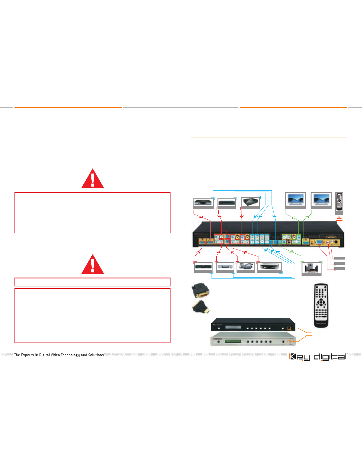
1. Connect your Sources to the Input and
Displays to the Output of your iSync HD [Pro]
Before applying power to your iSync HD [Pro]:
Connect your Digital (HDMI / DVI-D) and Analog (Component, Composite, S-Video) Video
sources (like your Set Top Box and DVD Player) to the Inputs of the iSync
Connect your displays to the Outputs of the iSync
Connect your Audio (Digital PCM, Toslink, Analog Stereo) to the Inputs and Outputs of the iSync
If applicable, you may connect your Control system (Crestron, AMX, Elan, Control 4, or virtually any
other control system) to the RS232C port of the iSync, but fi rst test the unit manually as described
below
Refer to the Application Example below for a typical confi guration of your iSync.
›
›
›
›
* To connect DVI-D video sources to the iSync HD [Pro]
inputs, use Key Digital DVI-D to HDMI adapters at the
output of your source.
** To connect displays with DVI-D inputs to the iSync
outputs, use Key Digital HDMI to DVI-D adapters at
the output of the iSync HD [Pro].
Front IR
Sensors
HDMI/HDCP
(or DVI* Video)
HDMI/HDCP
(or DVI* Video)
Component
Video
Surround Sound
Display
L&R or PCM Audio L&R or PCM Audio
Toslink Optical Audio
L&R, PCM, or
Toslink Optical Audio
HDMI/HDCP
(or DVI* Video)
S-Video or
Composite Video
Component
Video
Component
Video
Component
Video
S-Video
DVD Player
Cable Box
*To connect DVI-D Video use HDMI to DVI adapter
Game Console
Video Camera
Display
VCR
DVR Player
IR
Remote
HDTV Set Top Box
L&R or PCM Audio L&R or PCM Audio
Toslink Optical Audio
RS-232
Rear IR
Wired IR
(or DVI** Video)
Page 3
iSync HD / iSync Pro Quick Reference Guide
Page 4
iSync HD / iSync Pro Quick Reference Guide
Page 5
2. Confi guring your iSync HD [Pro]
Once your preferred components have been connected to the appropriate Input and Output ports
using the proper cabling and connectors, you are ready to begin confi guring your iSync HD [Pro] for
operation in your installation.
To confi gure your unit, use either the on-board navigating keys located on the face of the unit, or the
supplied IR remote control (with its convenient “Hot Buttons”) to directly access and adjust basic
picture quality parameters; and associate Audio components to a specifi c Video source.
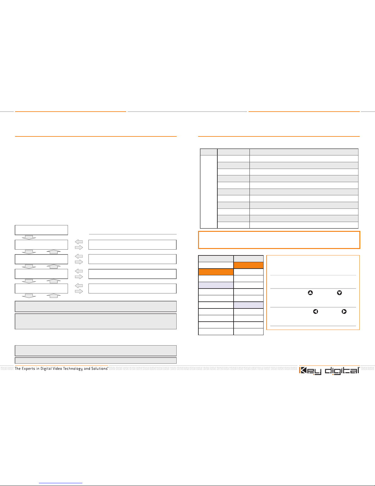
View menu headings and associated parameter adjustments on the convenient LCD screen
on the face of the unit:
1. Press the
MENU button: See the input and output screen resolutions.
2. Press the
MENU button again: The desired output screen resolution is ready to be selected.
3. Press the
RIGHT or LEFT arrow buttons to select desired screen resolution.
4. Press the
UP or DOWN arrow button to select the next parameter.
5. Press the
RIGHT or LEFT arrow button to change the selected parameter setting.
RIGHT & LEFT arrows will scroll through the available settings of each selected parameter in
a continuous loop.
Function selection is voided when no key is depressed for more than 30 seconds.
➔
➔
Pressing the MENU button a second time will display the last heading accessed on the MENU tree
and prompt the user, by means of left and right pointing arrows bracketing that heading, to access
the sub-menu.
The LEFT and RIGHT buttons will scroll through the content of an individual sub-menu associated with a
particular parameter, in a continuous loop, until such time that the user either exits the system by pressing
the MENU button or resumes scrolling through the SUB-MENU using the UP and DOWN buttons.
Pressing the MENU button once will display the current status of the Video formats present at the
input and output of the iSync HD [Pro] on the on-board LCD screen.
Successively pressing either the UP or DOWN button will access, in a continuous loop, all the
headings tabulated in the SUB-MENU column.
Pressing either the LEFT or RIGHT button will access items listed in the SUB-MENU.
IN: 720x480p @ 60Hz
OUT: 720x480p @ 60Hz
[ OUT RESOLUTION ]
< 1280x720p @ 60Hz >
ASPECT
< FULL SCREEN >
IN COLOR SPACE
< AUTO >
OUT COLOR SPACE
< RGB >
Select desired Output Resolution,
such as 1280 x 720p @ 60 Hz
Select desired Aspect Ratio Conversion,
such as Full Screen, Letterbox, H-Zoom, etc.
Select desired HDMI Input Color Space,
such as Automatic
Select desired HDMI Output Color Space,
such as RGB
Examples
3. Audio / Video Associations
For proper operation of your iSync HD [Pro] unit, you must associate each Audio component to a
specifi c Video source.
MENU SUBMENU DESCRIPTION
1. HDMI1 Associate HDMI1with audio input # ( 0 ~ 11 )
2. HDMI2 Associate HDMI2 with audio Input # ( 0 ~ 11 )
3. Component1 Associate Component1 with audio input # ( 0 ~ 11 )
4. Component2 Associate Component2 with audio input # ( 0 ~ 11 )
5. Component3 Associate Component3 with audio input # ( 0 ~ 11 )
6. Composite1 Associate Composite1 with audio input # ( 0 ~ 11 )
7. Composite2 Associate Composite2 with audio input # ( 0 ~ 11 )
8. Composite3 Associate Composite3 with audio input # ( 0 ~ 11 )
9. S-Video1 Associate S-Video1 with audio input # ( 0 ~ 11 )
10. S-Video2 Associate S-Video2 with audio input # ( 0 ~ 11 )
11. Default Setting up Default for all properties of the A/V association
A/V Association
For Example, Stereo Input 1 can be associated with HDMI Input 2; Coax Input 3 can be
associated with Component Input #2. Use the table below as an example guide to map
your associations.
VIDEO INPUT AUDIO INPUT
1. HDMI1 1. Stereo #1
2. HDMI2 2. Stereo #2
3. Component #1 3. Stereo #3
4. Component #2 4. Stereo #4
5. Component #3 5. Coaxial #1
6. Composite #1 6. Coaxial #2
7. Composite #2 7. Coaxial #3
8. Composite #3 8. Coaxial #4
9. S-Video #1 9. Optical #1
10. S-Video #2 10. Optical #2
11. None
You must make “Audio / Video”
associations, to link each Video Input to the
desired source of Audio
1. Scroll through the MENU until you reach
“TO ADJUST A/V ASSOCIATION”
2. First, use the UP and DOWN arrow
pushbuttons (at the SUB-MENU) to
select the Video Input of interest
3. Then, use the LEFT
and RIGHT
pushbuttons to associate the appropriate
Audio source with that Video Input
Page 4

iSync HD / iSync Pro Quick Reference Guide
Page 6
iSync HD / iSync Pro Quick Reference Guide
Page A
4. MENU
As you scroll through the MENU [by stepping through using the MENU pushbutton] and each SUBMENU [by stepping through using the UP
and DOWN arrow pushbuttons once you are at the
desired MENU item] of your iSync HD [Pro] unit, you can observe the status on the front-panel LCD.
Then, specifi c SUB-MENU settings can be made using the LEFT
and RIGHT arrow
pushbuttons.
The entire Menu structure is provided here for your convenience.
UP and DOWN arrows navigate to each SUB-MENU entry
To Select Your
Input Video
See
Page A
To Ad ju st
Picture
See
Page B
To Ad ju st
Screen
See
Page C
To Adjust A/V
Association
See
Page D
To Adjust Output
Resolution
See
Page E
To Ad ju st
Hidden
See
Page J
To Ad ju st
Hot Keys
See
Page I
To Ad ju st
Factory Default
See
Page H
To Ad ju st
Test Pattern
See
Page G
To Ad ju st
Set-Up
See
Page F
MENU
MENU - Page A
UP and DOWN arrows navigate to each SUB-MENU entry
MENU
To Select
Your Input Video
HDMI1
HDMI2
Component #1
Component #2
Component #3
Composite #1
Composite #2
Composite #3
S-Video #1
S-Video #2
›
›
›
›
›
›
›
›
›
›
Page 5

iSync HD / iSync Pro Quick Reference Guide
Page B
iSync HD / iSync Pro Quick Reference Guide
Page C
MENU - Page C
UP and DOWN arrows navigate to each SUB-MENU entry
LEFT
and RIGHT arrows select the desired value for SUB-MENU entry
MENU
To Adjust
Screen
First, select parameter
to adjust:
Horizontal Position
Vertical Position
Horizontal Size
Vertical Size
Horizontal O ffset
Vertical Offset
Default
›
›
›
›
›
›
›
Then choose your setting,
Factory Default indicated ():
( 0 ) / -20 ~ 20
( 0 ) / -20 ~ 20
( 0 ) / -20 ~ 20
( 0 ) / -20 ~ 20
( 0 ) / -20 ~ 20
( 0 ) / -20 ~ 20
( None ) / Yes/No
›
›
›
›
›
›
›
MENU - Page B
UP and DOWN arrows navigate to each SUB-MENU entry
LEFT
and RIGHT arrows select the desired value for SUB-MENU entry
MENU
To Adjust
Picture
First, select parameter
to adjust:
Contrast
Brightness
Saturation
Tint
Sharpness
Aspect
PAL Film
Picture Default
›
›
›
›
›
›
›
›
Then choose your setting,
Factory Default indicated ():
( 0 ) / -50 ~ 50
( 0 ) / -50 ~ 50
( 0 ) / -50 ~ 50
( 0 ) / -50 ~ 50
( 0 ) / -50 ~ 50
(DEFAULT) / Full Screen
Letter B ox
Pillar Box
H-Zoom
V-Zoom
H-V-Zoom
( Off ) / On-Off
Yes / No to select ALL
“Picture” Factory Defaults
›
›
›
›
›
›
➔
➔
➔
➔
➔
›
›
Page 6

iSync HD / iSync Pro Quick Reference Guide
Page D
iSync HD / iSync Pro Quick Reference Guide
Page E
MENU - Page E
UP and DOWN arrows navigate to each SUB-MENU entry
LEFT
and RIGHT arrows select the desired value for SUB-MENU entry
MENU
To Select Output
Resolution
Select the desired output resolution for
your display:
1920 x 1080P (60 Hz / 50 Hz)
1920 x 1080I (60 Hz / 50 Hz)
1400 x 1050P (60 Hz / 50 Hz)
1280 x 768P (60 Hz / 50 Hz)
1280 x 720P (60 Hz / 50 Hz)
1366 x 768P (60 Hz)
1920 x 540P (60 Hz)
720 x 480P (60 Hz)
720 x 480I (60 Hz)
720 x 576P (50 Hz)
720 x 576I (50 Hz)
1920 x 1080 SP (24 Hz)
Default [720 x 480P (60 Hz)] / Yes-No
›
›
›
›
›
›
›
›
›
›
›
›
›
MENU - Page D
UP and DOWN arrows navigate to each SUB-MENU entry
LEFT
and RIGHT arrows select the desired value for SUB-MENU entry
MENU
To Create A/V Association
[Link Audio to Specifi c Video Inputs]
First, select Video Input
of interest:
HDMI1
HDMI2
Component1
Component2
Component3
Composite1
Composite2
Composite3
S-Video1
S-Video2
Default
›
›
›
›
›
›
›
›
›
›
›
Then, make the desired
Audio Association:
Associate HDMI1with audio
input # ( 0 ~ 11 )
Associate HDMI2 with audio
Input # ( 0 ~ 11 )
Associate Component1 with
audio input # ( 0 ~ 11 )
Associate Component2 with
audio input # ( 0 ~ 11 )
Associate Component3 with
audio input # ( 0 ~ 11 )
Associate Composite1 with
audio input # ( 0 ~ 11 )
Associate Composite2 with
audio input # ( 0 ~ 11 )
Associate Composite3 with
audio input # ( 0 ~ 11 )
Associate S-Video1 with
audio input # ( 0 ~ 11 )
Associate S-Video2 with
audio input # ( 0 ~ 11 )
Default for all properties of the
A/V association
›
›
›
›
›
›
›
›
›
›
›
Page 7

iSync HD / iSync Pro Quick Reference Guide
Page F
iSync HD / iSync Pro Quick Reference Guide
Page G
MENU - Page G
UP and DOWN arrows navigate to each SUB-MENU entry
LEFT
and RIGHT arrows select the desired value for SUB-MENU entry
MENU
To Display a
Te s t P a t te rn
MENU - Page F
UP and DOWN arrows navigate to each SUB-MENU entry
LEFT
and RIGHT arrows select the desired value for SUB-MENU entry
MENU
To Set Up Input &
Output Color Space
First, select the Color
Space you want to
adjust:
HDMI Input Color Space
HDMI Output Color
Space
HDMI Output Setup
Analog Output Setup
›
›
›
›
Then, set the Color Space you
want:
YPbPr
RGB
(DEFAULT) / Auto
YCb Cr
RGB
(DEFAULT) / Auto
(DEFAULT) / HDMI - DVI
(DEFAULT) / YCbCr - RGBHV
›
›
›
›
›
›
›
›
First, select the Test
Pattern for the Input or
the Output of the iSync:
Input Pattern
Output Pattern
›
›
Then, choose the desired Test
Patte rn:
( DEFAULT ) / Normal Display
Horizontal Ramp
Color Bars
( DEFAULT ) / Normal Display
Horizontal Ramp
Color Bars
Cross Hatch
Gray Scale
White Window
Wide Horizontal Ramp
Wide Vertical Ramp
›
›
›
›
›
›
›
›
›
›
›
Page 8

iSync HD / iSync Pro Quick Reference Guide
Page H
iSync HD / iSync Pro Quick Reference Guide
Page I
MENU - Page I
UP and DOWN arrows navigate to each SUB-MENU entry
LEFT
and RIGHT arrows select the desired value for SUB-MENU entry
MENU
Hot Keys
MENU - Page H
UP and DOWN arrows navigate to each SUB-MENU entry
LEFT
and RIGHT arrows select the desired value for SUB-MENU entry
MENU
To Set iSync
to Factory Default
The Default is not to invoke a Factory Default
You can select Yes-No to invoke a default at
this point in the MENU
›
Still
Mute
›
›
Turn Still On-Off
Turn Mute On-Off
›
›
MENU - Page J
UP and DOWN arrows navigate to each SUB-MENU entry
MENU
Hidden
EDID rewriting to Serial EEPROM
›
 Loading...