

Page 1
OPERATING INSTRUCTIONS
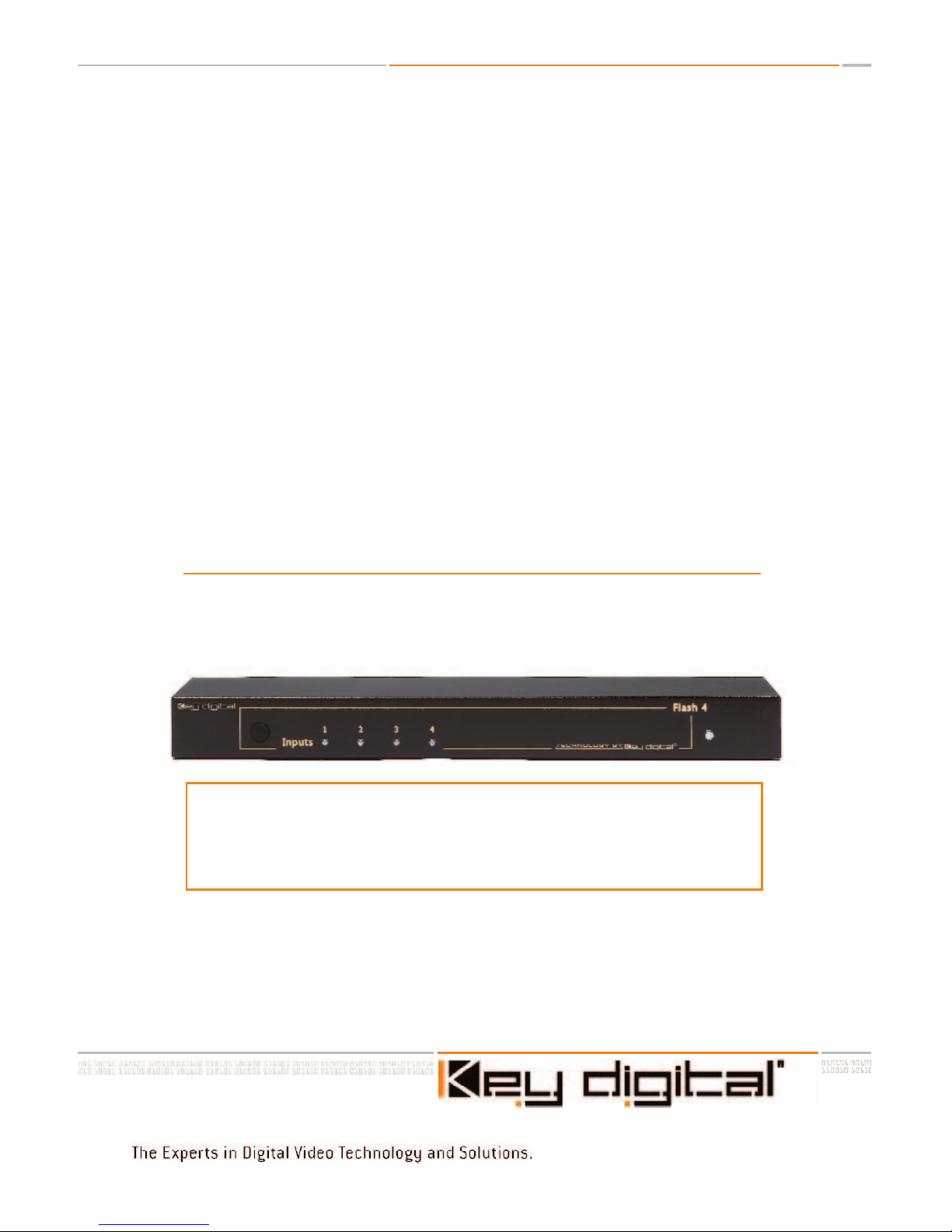
HD Flash 4
4 to 1 Component & RGBHV A/V Switcher
Model KD-SW4x1
Featuring 4 Inputs of Component (YPrPb)
Video and Audio (Analog L & R, Digital PCM)
or up to 4 Inputs Video (R,G,B,H,V)
and Audio (Digital PCM)
TM
Page 2

HD Flash 4TM/ Model KD-SW4x1
Safety Instructions – Please be sure to follow these
instructions for safe operation of your unit
1
Read these instructions.
2
Keep these instructions.
3
Heed all warnings.
4
Follow all instructions.
5
Do not use this apparatus near water
6
Clean only with dry cloth.
7
Do not block any ventilation openings. Install in accordance with the manufacturer’s
instructions.
8
Do not install near any heat sources such as radiators, heat registers, stoves, or other
apparatus (including amplifiers) that produce heat.
9
Do not defeat the safety purpose of the polarized or grounding-type plug. A polarized plug has two blades with one wider than the other. A grounding type plug has
two blades and a third grounding prong. The wide blade or the third prong are provided for your safety. If the provided plug does not fit into your outlet, consult an electrician for replacement of the obsolete outlet.
10
Protect the power cord from being walked on or pinched particularly at plugs, con-
venience receptacles, and the point where they exit from the apparatus.
11 Only use attachments/accessories specified by the manufacturer
12
Use only with the cart, stand, tripod, bracket, or table specified by the manufacturer,
or sold with the apparatus. When a cart is used, use caution when moving the
cart/apparatus combination to avoid injury from tip-over.
13
Unplug this apparatus during lightning storms or when unused for long periods of
time.
14
Refer all servicing to qualified service personnel. Servicing is required when the
apparatus has been damaged in any way
, such as power
-supply cord or plug is
damaged, liquid has been spilled or objects have fallen into the apparatus, the apparatus has been exposed to rain or moisture, does not operate normally, or has been
dropped.
HD Flash 4TMOperating Instructions
Page 2 of 12
Page 3
Page 3 of 12
HD Flash 4TMOperating Instructions
Introduction
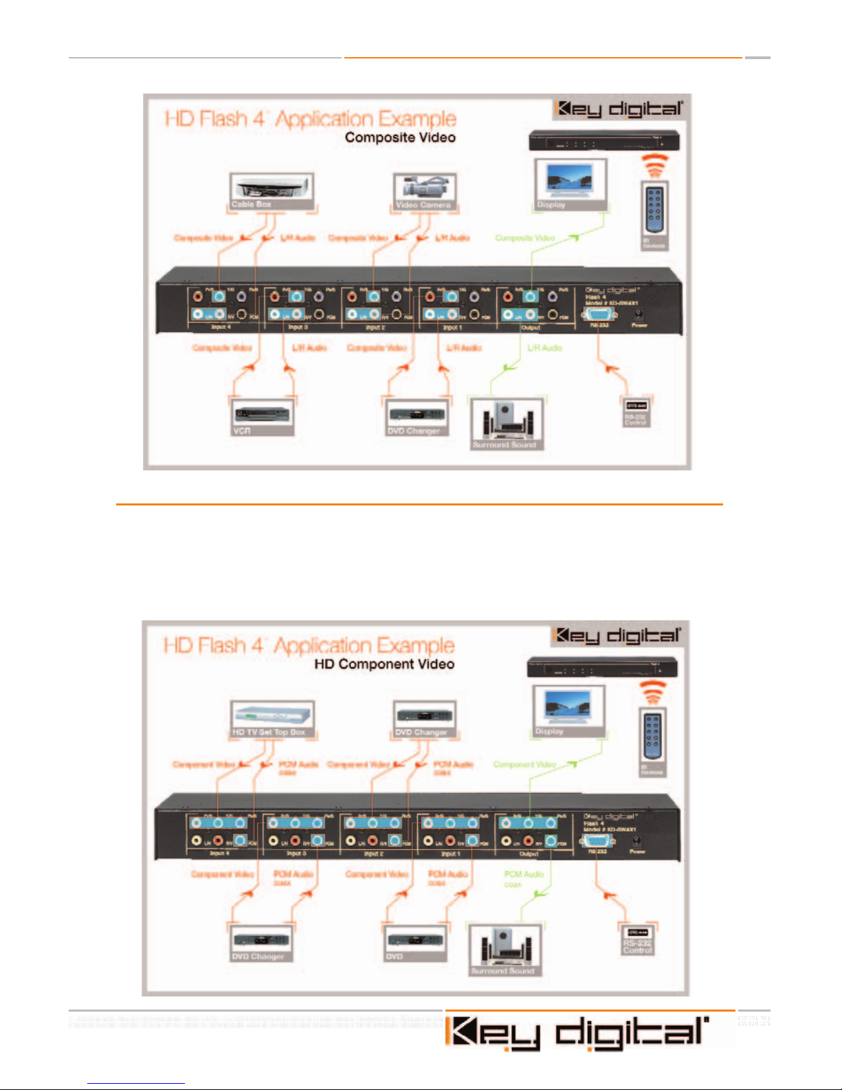
Key Digital®HD Flash 4TM(Model KD-SW4x1) is a versatile multi-input audio/video switcher
for connecting video and audio sources to a TV video display or monitor. It is the ideal solution when your TV, monitor, or receiver does not have enough video and audio inputs. It features 4 independent component video/audio inputs with one component video/audio output.
Digital audio (PCM)or analog audio (L & R) can also be switched through the Flash 4
TM
. All
input selections are clearly displayed on the front panel with blue LED indicators.
Page 4
Using the Flash 4TM, you can switch the virtaully any A/V input device
• DVD players
• Electronic game boxes
• Cable TV, satellite, and terrestrial DTV set-top receivers
• Digital video recorders (DVRs)
• D-VHS, S-VHS, and VHS VCRs
You can also switch S-Video (with adapter) and composite (single-wire) video signals from
VCRs, digital video recorders, and satellite set-top receivers through the Flash 4
TM
.
Color-coded RCA jacks are provided on the rear panel for fast and easy hook-up.
Switching can be done in any of three ways:
• Manually, using the front panel button.
• Remotely, using the supplied infrared remote control
• Remotely, using a touch panel and RS-232 commands
Connecting Your A/V Equipment
Connecting your A/V equipment to the Flash 4TMis a simple process. Start with Input #1 and
proceed to the next higher input each time you add an A/V device.
First, determine the video signal format you want to connect. If an A/V device has component YPrPb (three-wire) video outputs, use them for best video quality. If component video
outputs are not available, use the S-Video output instead. Composite video signals can also
be switched through the Flash 4
TM
, but these signals will have the lowest overall video quality.
This is comparative statement for Component, S-Video or Composite formats. The Flash 4
TM
does not degrade any HDTV or SDTV video signal.
Next, deter
mine whether you want to use the device’
s analog audio outputs or the digital
audio output. Use analog outputs if you ar
e switching audio to the analog inputs of a TV or
monitor. Use the digital output if you are switching audio to an A/V receiver with a digital
audio input.
HD Flash 4TMOperating Instructions
Page 4 of 12
Page 5

Warning - do not connect a digital audio output signal to analog inputs on your TV or monitor! It may damage your speakers!
The Flash 4TMis wired with RCA female connectors. Switching S-Video will require special
S-Video to RCA breakout cables for inputs and outputs.
Connecting a digital TV set-top receiver with componentYPrPb (three-wire) video outputs to
the Flash 4
TM
Connect the three-wire green, red and blue (YPrPb) jacks on your set-top receiver to the
green, red, and blue (YPrPb) jacks on the Flash 4
TM
. Connect the white and red analog
stereo audio output jacks on your set-top receiver to the white (L/H) and red (R/V) input
jacks on the Flash 4
TM
. If you have a digital audio output jack on your receiver, you can con-
nect it to the black (PCM) input jack on the Flash 4
TM
. Connect the green, red, and blue
(YPrPb) jacks from Output on the Flash 4
TM
to the corresponding component video jacks on
your TV or monitor. Connect the white (L/H) and red (R/V) analog audio jacks to the corresponding audio jacks on your TV or monitor.
If you wish to listen to digital audio from your set-top receiver,and you have connected the
digital ouput of your set-top receiver to the PCM input of the Flash 4
TM
, connect a cable
from the black (PCM) output jack to your A/V receiver’s digital audio input.
Do not connect this output to analog audio inputs on your TV or monitor!
Page 5 of 12
HD Flash 4TMOperating Instructions
Page 6

HD Flash 4TMOperating Instructions
Page 6 of 12
Connecting a DVD player or game console with component YPrPb (three-wire) video outputs
to the Flash 4
TM
Connect the three-wire green, red, and blue (YPrPb) jacks on your DVD player or other A/V
component to the green, red, and blue (YPrPb) jacks on the Flash 4
TM
. Connect the white
and red analog stereo audio jacks on your component to the white (L/H) and red (R/V) input
jacks on the Flash 4
TM
. If you have a digital audio output jack on your device, you can con-
nect it to the black (PCM) jack on the Flash 4
TM
.
Connect the green, red, and blue output (YPrPb) jacks on the Flash 4
TM
to the corresponding component video jacks on your TV or monitor. Connect to white (L/H) and red (R/V)
analog audio jacks from the same output to the corresponding audio jacks on your TV or
monitor.
If you wish to listen to digital audio from your DVD player or game console and you have
connected the digital ouput of your DVD player or game console to the PCM input of the
Flash 4
TM
,, connect a cable from the black (PCM) output jack to your A/V receiver’s digital
audio input.
Do not connect this output to analog audio inputs on your TV or monitor!
Page 7

Page 7 of 12
HD Flash 4TMOperating Instructions
Connecting devices with S-Video or composite video outputs to the Flash 4
TM
S-Video connection: You will need an S-Video to RCA breakout cable to connect your satellite receiver, DVR, or S-VHS VCR to the Flash 4
TM
(A S-Video to composite video adapter is
also available with a single output connection. If using this adapter, follow the instructions for
connecting composite video signals.). The following directions only apply when using a two
wire RCA break out cable adapter.
Connect the white (Y) wire to the green (Y/G) jack on the desired input jack field, and connect the black (C) wire to either the blue (Pb/B) or red (Pr/R) jack. Connect the white and red
analog stereo audio jacks on your device to the white (L/H) and red (R/V) jacks on the Flash
4
TM
.
Plug the white (Y) wire of a second S-Video RCA adapter cable into the green (Y/G) output
jack of the Flash 4
TM
. Connect the black (C) wire of the adapter cable to the blue (Pb/B) or
red (Pr/R) jack on the Flash 4
TM
. Plug the other end into your TV or monitor’s S-Video input.
Connect the white and red analog stereo audio jacks to your TV or monitor.
Connect the composite video jack (typically black or yellow)) from your VCR or DVR to the
green (Y/G) input jack in the desired jack field. Connect another composite video cable from
the green (Y/G) output jack to your TV or video monitor.
Page 8

HD Flash 4TMOperating Instructions
Page 8 of 12
Selecting video/audio inputs using with the Flash 4
TM
On the front of the Flash 4TMthere is a pushbutton with a row of blue LED indicators. Each
LED corresponds to a separate video/audio input. To select a specific A/V device (input),simply push the button repeatedly until the LED indicator for the desired input is lit. All video
and audio signals connected to that input are automatically sent to the output.
Remote selection and switching of A/V inputs and outputs with the Flash 4
TM
(IR) Remote Control.
You can operate the Flash 4TMusing the supplied infrared (IR) remote control.
By pressing R1 and then one digit on the IR remote control, you go to the desired input.
The digit you enter corresponds to the desired video/audio input (1-4). For example, if you
wished to connect a DVD player on input 4, you would depress the key 4. When the R1 key
is pressed, the blue input LED indicators on the front panel will blink until a desired input
number is selected. If you prefer, you can press R1 and also use the CH+ and CH- keys on
the IR remote control to step through and select an input.
R3 Optional Mode of Operation.
The Flash 4
TM
may be located where other Key Digital®products are being used. Since the
Flash 4
TM
shares some remote commands with other Key Digital®products, it is necessary to
press the R1 button before entering a remote command. If you do not have any other Key
Digital
®
equipment nearby, you can set up the Flash 4TMto not require the use of the R1 button before you select an input. You do this by pressing R3 for 5 seconds. When you press
R3, the blue LED input indicator on the Flash 4
TM
will blink. Keep pressing the R3 button
until it stops blinking. You can now control the Flash 4
TM
input selector without pressing R1
first. If you want to go back to the mode where you press R1 first, press R3 again for 5 seconds. Even if you are in the R3 optional mode, you can still press R1 first if you wish.
RS-232 Control and Multiple Unit Operation
The Flash 4
TM
can be controlled remotely through its RS-232 and IR ports from AMX,
Crestron, and Dataton systems using the protocol and commands below.
RS232 Protocol
Band Rate 4800
8 data bits
1 stop bit
No parity
Page 9

Page 9 of 12
HD Flash 4TMOperating Instructions
RS232 Commands
Switching Command
CCx (x=video/audio input [1..4])
Status Command
CCw
Since both commands are of a defined length, no terminator is required
Both commands give the following respose.
Uuyn
y – currently selected video/audio input [1..4]
n – firmware version number (the two digits which may be required by the factory for troubleshooting)
A response will be returned for all switching events, whether from the front panel, IR or
RS232 port so that the controller is always aware of the current status of the Flash 4
TM
.
Technical Specifications
Flash 4TMFlash Matrix A/V Switcher
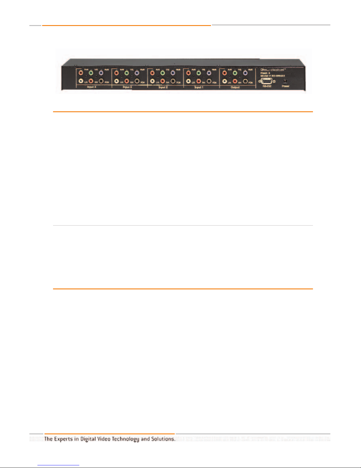
Inputs:
4 input groups, each consisting of (3) component YPrPb analog RCA jacks, (2) stereo analog
audio RCA jacks, and (1) PCM digital audio RCA jack.
Video:
Three RCA-type color-coded input jacks (Y, Pr, Pb) 1V p-p @ 75 ohms, terminated
Composite video sync on "Y" input
Audio:
Two RCA-type color-coded input jacks (L, R)
High impedance (1K ohm) line level inputs
Digital Audio:
One RCA-type color-coded input jack
Standard PCM digital format
Page 10

Compatible Video Signals:
All standard analog video signal formats that use 50 Hz or 60 Hz
refresh are accepted, including 480i, 480p, 576i, 576p, 540p/1080i, and 720p
Bandwidth:
-3 dB @ 300 MHz, linear phase passband
Video Gain:
Unity gain for Y, Pr, Pb, channels
Mechanical:
Size: 17" x 10" x 3.5"
Weight: 10 lbs.
Enclosure Type: Metal
Rack Mount Size: 2 RU, brackets included
Power Requirements: 100-240VAC, 0.9A
Key Features
• Ensures flawless switching for up to 4 inputs of Component (YPrPb) Video and Audio
(L,R, digital PCM) or up to 4 inputs of R,G,B,H,V plus digital PCM Audio.
• Any SDTV and HDTV formats accepted 480i, 576i, 480p, 576p,1080i/540p & 720p.
• Front panel manual control button.
• All video inputs and outputs have female RCA cable connectors.
• Infrared Remote
• Manual control button on front panel.
• S-Video, Composite, Component and RGBHV switching.
• RS 232 port provides connection to and direct access control systems such as Crestron,
AMX, Panja, Dataton.
• Rack mountable - 1U.
• 2 years parts and labor limited warranty.
HD Flash 4TMOperating Instructions
Page 10 of 12
Page 11

HOW TO CONTACT KEY DIGITAL
®
Repairs and Warranty Service:
n
Should your HD Flash 4
TM
require warranty service, please contact Key Digital®to obtain a
Returned Materials Authorization (RMA) number
n
Please contact us at either:
n
1-914-667-9700
n
email tech@keydigital.com
Technical Support:
n
For technical questions about using our products, please contact us at either:
n
1-914-667-9700 or Toll-free 1-888-258-2028
n
email tech@keydigital.com
Customer Support
n
For customer support questions about using our products, please contact us at either:
n
1-914-667-9700
n
email customersupport@keydigital.com
WARRANTY
All Key Digital®products are built to high manufacturing standards and should provide years of
trouble-free operation. They are backed by a limited two-year parts and labor warranty.
Page 11 of 12
HD Flash 4TMOperating Instructions
Page 12

Web :: www.keydigital.com
Phone
:: 914-667-9700 Fax :: 914-668-8666
Key Digital®, led by digital video pioneer Mike Tsinberg,
develops and manufactures high quality, cutting-edge
technology solutions for virtually all applications where
high quality video imaging is important. Our products are
used by professional broadcasters, corporations, cus-
tom installers, home theater retailers, and consumers.
HD Flash 4TMOperating Instructions
 Loading...