

Page 1
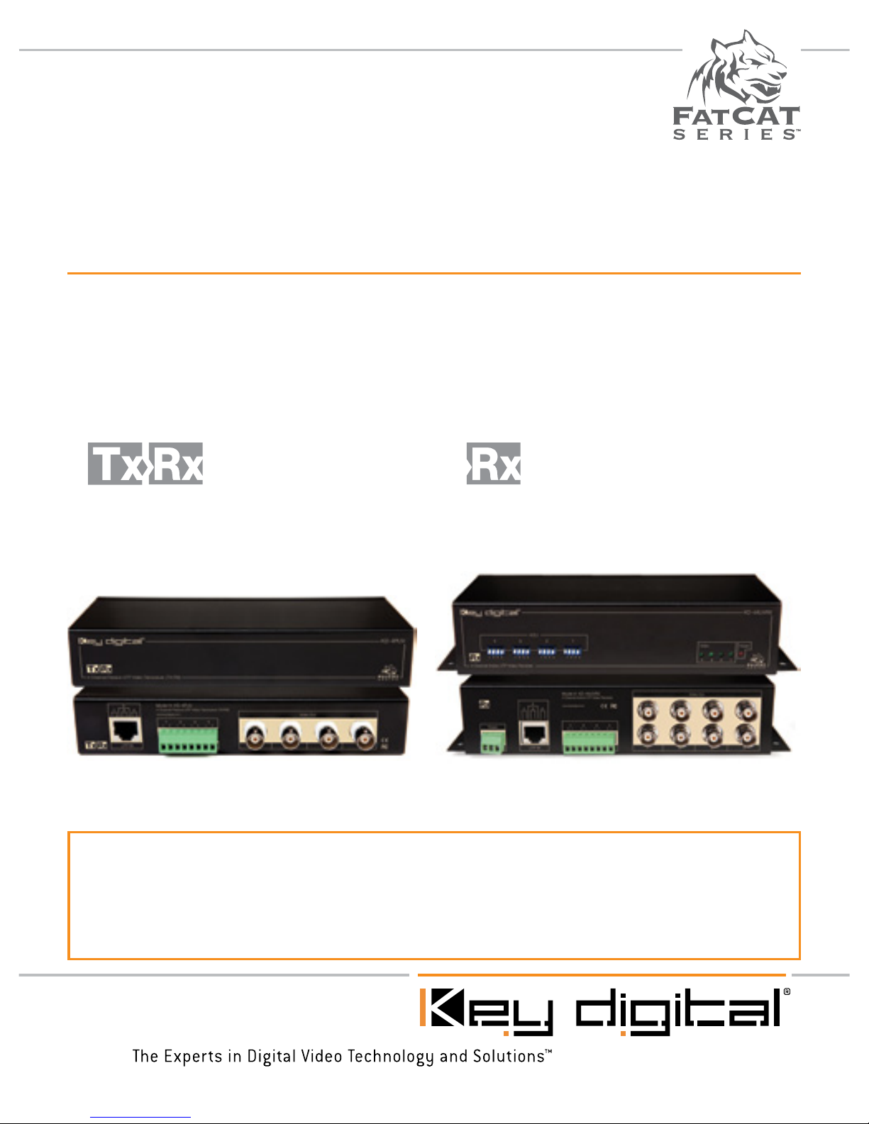
KD-4AUVRX & KD-4PUV are multi-channel video hubs that allow for the
transmission or reception of Color or Black & White single-channel video signals
up to 4,000 feet (KD-4AUVRX) or 2,600 feet (KD-4PUV) with standard, unshielded
CAT5 cabling.
KD-4PUV
Four Channel Passive Video
Transceiver
KD-4AUVRX
Four Channel Active Video
Receiver
4 Channel Security Hubs
Operating Instructions
Page 2

Page 2
Please read all instructions to insure safe operation of the product.
Table of Contents
KD-4AUVRX
About KD-4AUVRX . . . . . . . . . . . . . . . . . . . . . . . . . . . . . . . . . . . . . . . . . . . . . . . . 2
Installation and Operation. . . . . . . . . . . . . . . . . . . . . . . . . . . . . . . . . . . . . . . . . . . . 2
Video Connections . . . . . . . . . . . . . . . . . . . . . . . . . . . . . . . . . . . . . . . . . . . . . . 2
Power Connections . . . . . . . . . . . . . . . . . . . . . . . . . . . . . . . . . . . . . . . . . . . . . 2
Uses with Active Transmitters . . . . . . . . . . . . . . . . . . . . . . . . . . . . . . . . . . . . . . 3
Uses with Passive Transceivers & Multi-Channel Receivers / Transceivers . . . . . 3
Distance Adjustment Settings . . . . . . . . . . . . . . . . . . . . . . . . . . . . . . . . . . . . . . . . 3
Mechanical / Technical Specifications . . . . . . . . . . . . . . . . . . . . . . . . . . . . . . . . . . 5
KD-4PUV
About KD-4PUV . . . . . . . . . . . . . . . . . . . . . . . . . . . . . . . . . . . . . . . . . . . . . . . . . . 2
Installation and Operation. . . . . . . . . . . . . . . . . . . . . . . . . . . . . . . . . . . . . . . . . . . . 2
Video Connections . . . . . . . . . . . . . . . . . . . . . . . . . . . . . . . . . . . . . . . . . . . . . . 2
Uses with Passive Multi-Channel Receivers . . . . . . . . . . . . . . . . . . . . . . . . . . 3
Uses with Active Receivers & Active Multi-Channel Receivers . . . . . . . . . . . . . . 3
Distance Adjustment Settings . . . . . . . . . . . . . . . . . . . . . . . . . . . . . . . . . . . . . . . . 3
Mechanical / Technical Specifications . . . . . . . . . . . . . . . . . . . . . . . . . . . . . . . . . . 5
Key Digital
®
Security Products Compatibility Chart . . . . . . . . . . . . . . . . . . . . . . . . . 4
Important Product Warnings . . . . . . . . . . . . . . . . . . . . . . . . . . . . . . . . . . . . . . . . . 6
Safety Instructions . . . . . . . . . . . . . . . . . . . . . . . . . . . . . . . . . . . . . . . . . . . . . . . . . 6
How to Contact Key Digital . . . . . . . . . . . . . . . . . . . . . . . . . . . . . . . . . . . . . . . . . . 7
Warranty . . . . . . . . . . . . . . . . . . . . . . . . . . . . . . . . . . . . . . . . . . . . . . . . . . . . . . . . 8
Page 3
Page 1
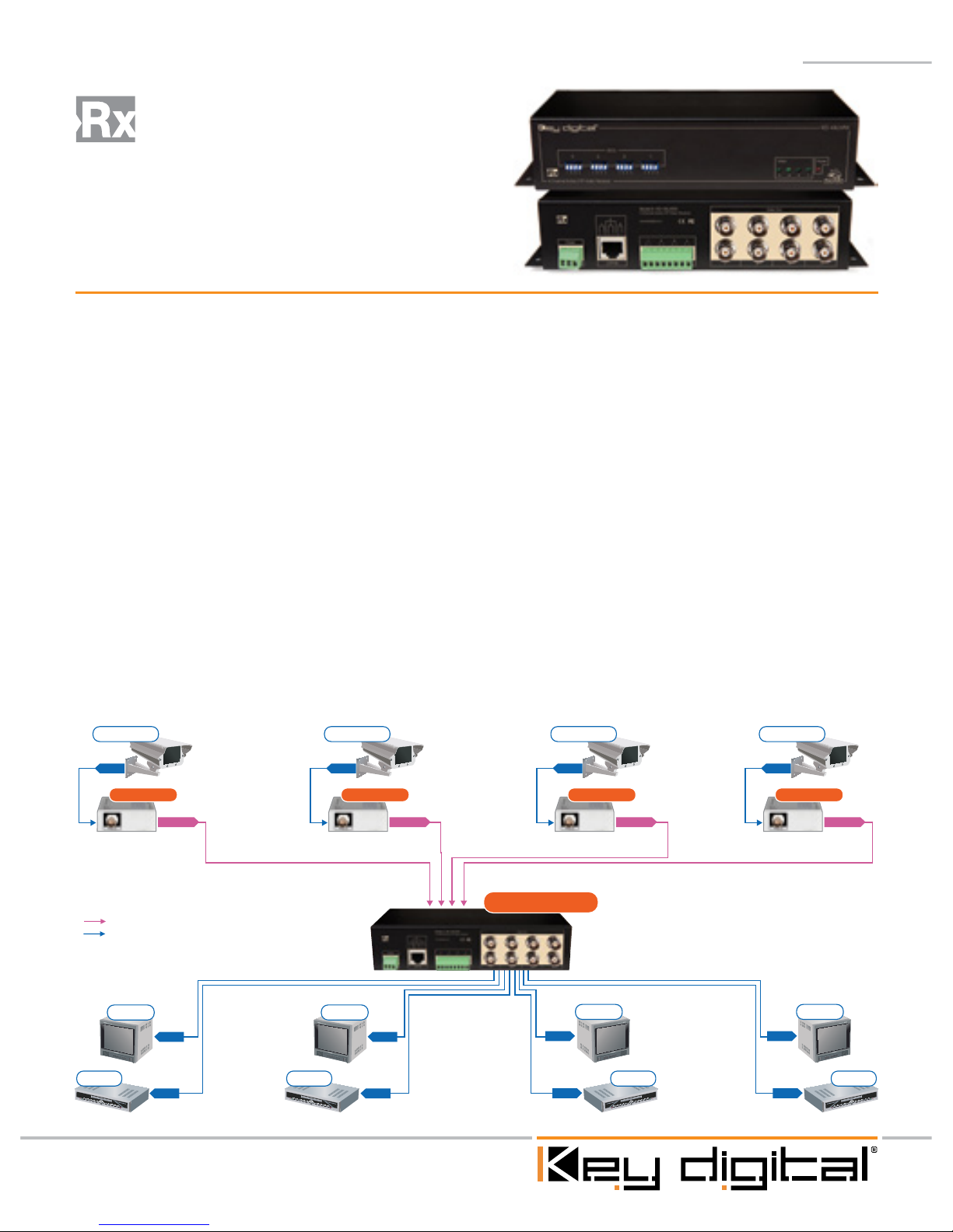
Quick Setup Guide
Step 1: Begin with all input/output devices turned off with power cables removed
Step 2: Connect video source, CAT5/6/7 cabling, and Power into Active or Passive
Transmitter Baluns
Step 3: Insert twisted pair wires into “UTP In” Phoenix Connector or “UTP In”
CAT5/6/7 RJ45 connector as instructed on chassis above RJ45 input.
See “Video Connections” section.
Step 4: Connect video display and/or DVR to “Video Out” of KD-4AUVRX
Receiver Hub
Step 5: Secure + and – power wires into Phoenix Connector “Power” inputs
Step 6: Make appropriate settings to “Distance Adjustment” dip switches. See
“Distance Adjustment Table” section
Step 7: Power on all input/output devices
CAT5/6/7
Video
4,000’
CAT5/6/7
Video
CAT5/6/7
Video
CAT5/6/7
Video
CAT5/6/7
Video
Video
Video Video
Video
Video Video
Video Video
Monitor
DVR
Monitor
DVR DVR
Monitor Monitor
DVR
KD-AUVTX
KD-4AUVRX
KD-AUVTX KD-AUVTX KD-AUVTX
Security Cam Security Cam Security Cam Security Cam
KD-4AUVRX
Four Channel Active Video
Receiver
Page 4
Page 2
About KD-4AUVRX
➔ Receives real-time Color or Black & White video
➔ KD-AUVTX Extends video up to 4,000 ft using a standard CAT cable when used
with an Active Transmitter (Key Digital Model KD-AUVTX).
➔ KD-4AUVRX extends video up to 2,600 ft when used with a Passive Transmitter
Balun (Key Digital Models KD-PVB and KD-4PUV)
➔ Manual Distance Adjustment switches for optimum picture quality at any length
run up to 4,000 ft.
➔ Built-in interference rejection enables wire bundling with other low-voltage lines
➔ Built-in surge protection, ground loop isolation, gain and loss control, and video
detection
➔ Compatible with CAT5/CAT5e/CAT6/CAT7 cabling
➔ Works with generic power supplies, from DC/AC 9V to 12 V (not included)
Installation and Operation
Before permanently securing the unit for final installation of
cabling behind walls or ceilings, test for proper operation of the
unit and the cables in your system.
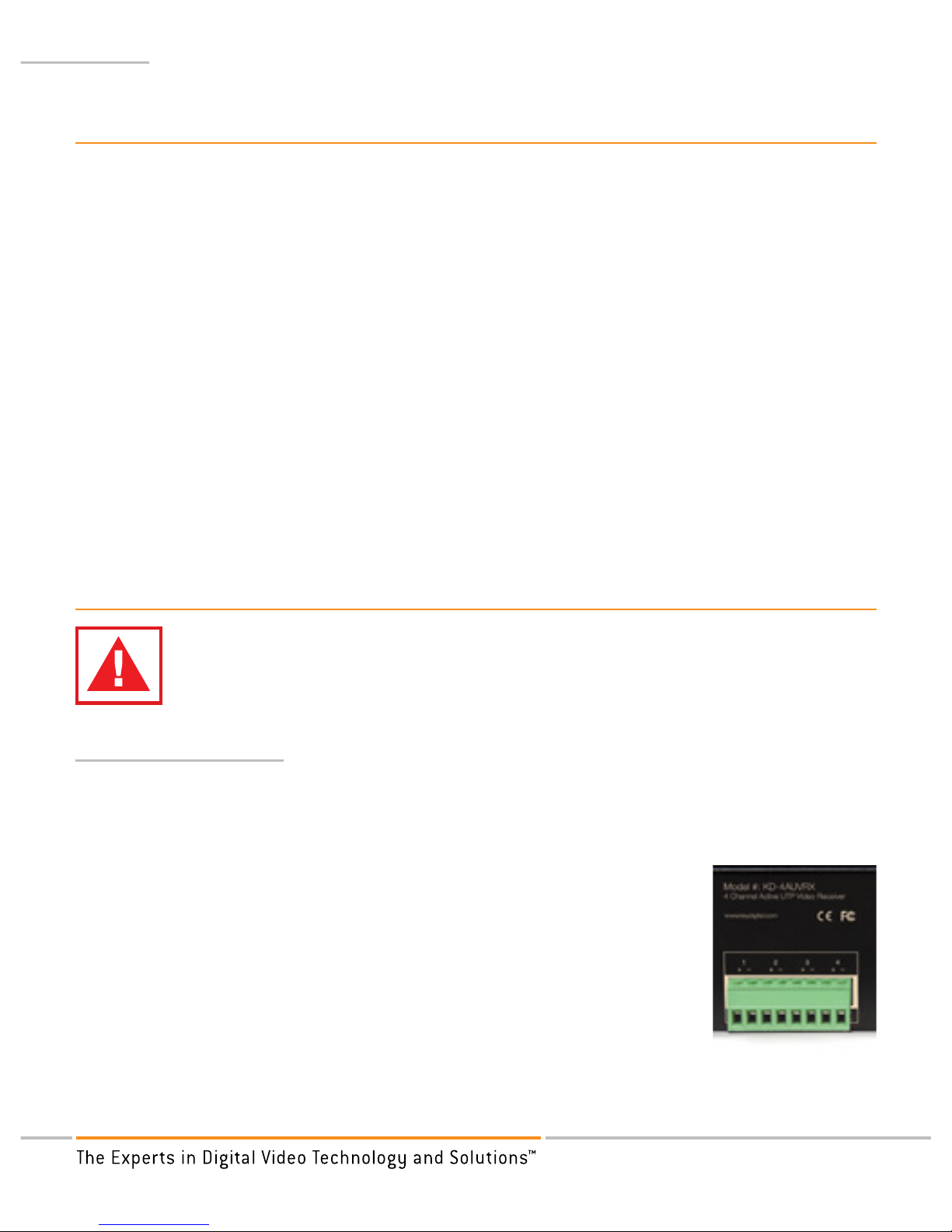
Video Connections
➔ KD-4AUVRX features two input options for video reception; a RJ45 port labeled
“UTP In” and a Phoenix Connector labeled “UTP In”. It is recommended that only
one of the two options be utilized as the CAT5/6/7 input.
» Phoenix Connector: Secure twisted pair wires into “Video
+” and “Video -” of Phoenix Connector block by loosening
screws, inserting twisted pairs, and tightening screws until
connection is secured. If using shielded CAT cabling, you
may insert shield into Pin 3 of Phoenix Connector.
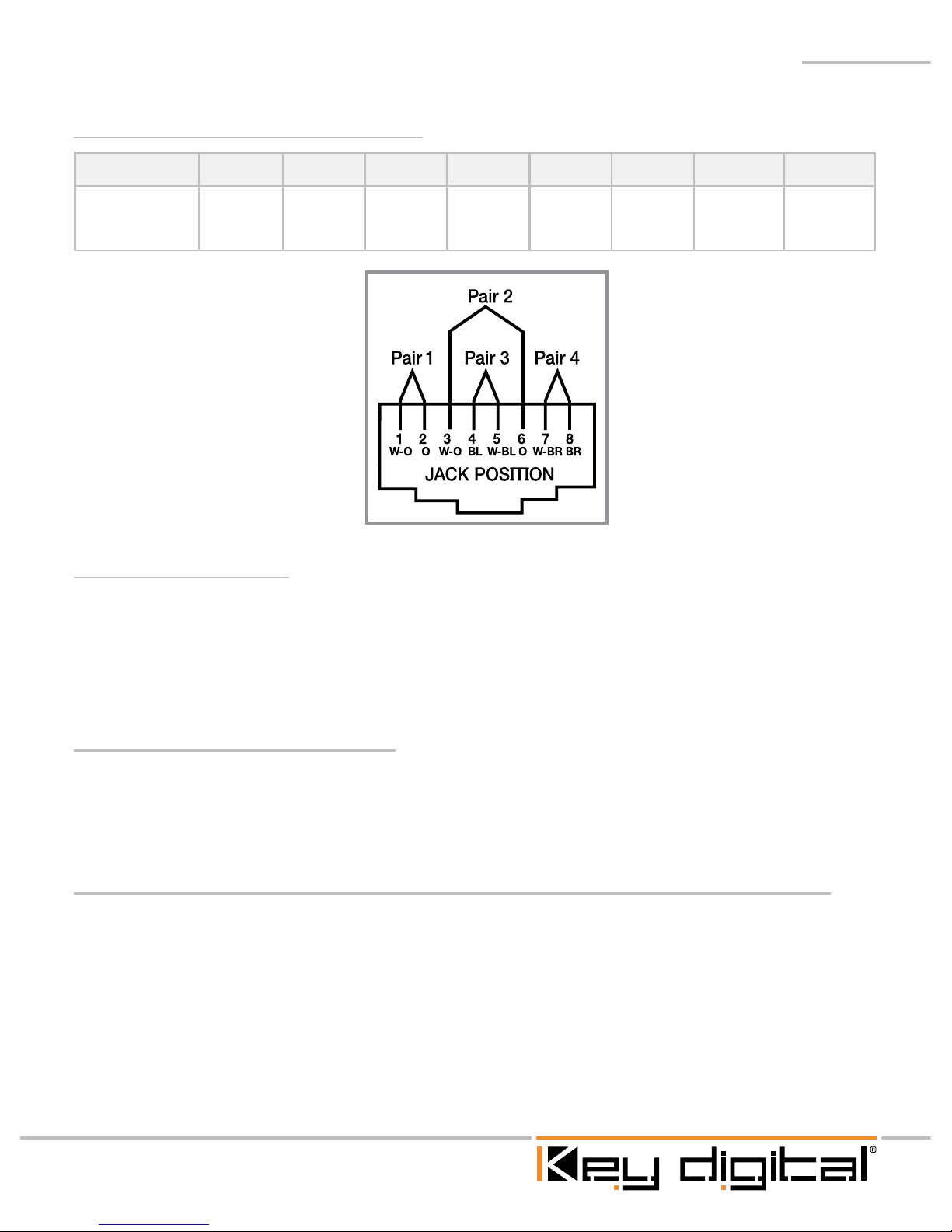
» RJ45: Terminate the incoming CAT5/6/7 twisted pair wires
into your RJ45 connector in the following fashion:
Page 5
Page 3
Pin Assignment for KD-4AUVRX
Pin# 1 2 3 4 5 6 7 8
Description Pair 1
+
Pair 1
-
Pair 2
+
Pair 3
+
Pair 3
-
Pair 2
-
Pair 4
+
Pair 4
-
Power Connections
➔ Secure + and – power wires into “Power” inputs (Pin 1 and Pin 2) of Phoenix
Connector in the same fashion as securing Video connections. Positive (+) and
Negative (-) polarity can be inserted into any of the two “Power” inputs. Insert
Ground wire into Pin 3 if desired.
Uses with Active Transmitters
➔ KD-4AUVRX units can be coupled with Key Digital’s KD-AUVTX Active Video
Transmitter as part of a multi-camera CCTV system. Using the KD-4AUVRX with
the KD-AUVTX Active Hub will provide quality video up to 4,000 ft.
Uses with Passive Transceivers & Passive Multi-Channel Transceivers
➔ KD-AUVRX units can be coupled with a passive Transmitter/Transceiver (Key
Digital model KD-PVB) or a passive Multi-Channel Transmitter/Transceiver (Key
Digital model KD-4PUV) in your application. Coupling a Passive Transmitter/
Transceiver with the KD-AUVRX Active Receiver Balun will provide quality video
up to 2,600 ft.
Page 6

Page 4
Distance Adjustment Settings
Dip Switch Configurations:
Configuration Distance
1111 1’-150’
0111 150’ – 800’
0100 800’ – 1300’
0010 1300’ – 2000’
1110 2000’ – 4000’
➔ Adjustments should be set identically on Transmit (KD-AUVTX) and Receiver
(KD-4AUVRX) unit.
➔ All distances listed above correspond to the pairing of active Transmit Balun
(KD-AUVTX) and Active Receive Balun (KD-4AUVRX).
CAT5/6/7
Video
4,000’
CAT5/6/7
Video
4,000’
CAT5/6/7
Video
CAT5/6/7
Video
CAT5/6/7
Video
CAT5/6/7
Video
Video
Video Video
Video
Video Video
Video Video
Video Video Video Video
CAT5/6/7
Video Video
Video
Video
Video Video
Video
Video
Monitor
DVR
Monitor
DVR DVR
Monitor Monitor
DVR
Monitor
DVR
Monitor
DVR DVR
Monitor Monitor
DVR
CAT5/6/7
KD-AUVTX
KD-4AUVRX
KD-AUVTX KD-AUVTX KD-AUVTX
KD-4AUVRX
KD-4PUV
Security Cam Security Cam Security Cam Security Cam
Security Cam Security Cam Security Cam Security Cam
Page 7

Page 5
Mechanical / Technical Specifications
Input
4 twisted pair from CAT5 line In on Phoenix type
stripping and cramping connector or 1 CAT5 on
RJ45 Connector
Output
2 BNC connector for Composite Video 1Vpp with
75Ω at display side or Audio SPDIF or any other
format of video, audio, RS-232 or IR signaling.
Max. Signal Input /
Output Level:
Composite: 1.2Vpp on 75Ω terminated at display, DC
coupling or Line Audio or TTL +5V for digital RS-232,
IR signaling
Surge Protection
Renewable solid state surge protection.
Bandwidth
DC to 6 MHz
Video Format
NTSC, PAL, SECAM
Impedance
BNC side 75Ω unbalanced,
UTP side 100Ω balanced
Humidity
0% to 95% non condensing
Distance
4000 feet Active Tx with Active Rx Coupling,
2000 feet Passive Tx with Active Rx coupling
Equalization and Gain
Adjustments
Passive impedance matching and fixed equalization.
Manual adjustment by dip switches for CAT5 cable
length measurement up to 4000 ft
Video S/N Ratio:
58 dB RMS un-weighted;
65 dB RMS @5MHz weighted
Ground Isolation
Ground connection available for STP or Ground
loop removal
Power Source:
DC/AC 9-12V
Dimensions:
WxDxH: 7.5”x3.3”x 1.75” excluding BNC
Weight:
2 lb
Operating Temperature
-14F to +120F
Accessories:
None
Page 8

Page 6
Quick Setup Guide
Step 1: Begin with all input/output devices turned off with power cables removed.
Step 2: Connect video source and CAT5/6/7 cabling to Transmitter/Receiver Baluns
Step 3: Insert twisted pair wires into “UTP In” Phoenix Connector or “UTP In”
CAT5/6/7 RJ45 connector as instructed on chassis above RJ45 input.
See “Video Connections” section.
Step 4: Connect video source, display and/or DVR to “Video Out” of KD-4PUV
Transceiver Hub
Step 5: Power on all input/output devices.
KD-4PUV
Four Channel Passive Video
Transceiver
CAT5/6/7
Video
1,300’
CAT5/6/7
Video
CAT5/6/7
Video
CAT5/6/7
Video
CAT5/6/7
Video
Video Video
Video Video
Monitor Monitor
Monitor Monitor
KD-4PUV
KD-PVB KD-PVB KD-PVB KD-PVB
Security Cam Securit y Cam Security Cam Security Cam
Page 9

Page 7
About KD-4PUV
➔ Transmits or Receives real-time Color or Black & White video
➔ Extends Black & White video up to 2,600 ft using a standard CAT cable when
used with an Active Receiver (Key Digital models KD-AUVRX or KD-4AUVRX).
➔ Extends Black & White video up to 1,300 ft using a standard CAT cable when
paired with a Passive Transmitter Balun (Key Digital models KD-PVB or KD-4PUV).
➔ Built-in interference rejection enables wire bundling with other low-voltage lines
➔ Compatible with CAT5/CAT5e/CAT6/CAT7 cabling
Installation and Operation
Before permanently securing the unit for final installation of
cabling behind walls or ceilings, test for proper operation of the
unit and the cables in your system.
Video Connections
➔ KD-4PUV features two options for video reception; a RJ45 port labeled “UTP In”
and a Phoenix Connector labeled “UTP In”. It is recommended that only one of the
two options be utilized as the CAT5/6/7.
» Phoenix Connector: Secure twisted pair wires into “Video
+” and “Video -” of Phoenix Connector block by loosening
screws, inserting twisted pairs, and tightening screws until
connection is secured. If using shielded CAT cabling, you
may insert shield into Pin 3 of Phoenix Connector.
» RJ45: Terminate the incoming CAT5/6/7 twisted pair wires
into your RJ45 connector in the following fashion:
Pin Assignment for KD-4AUVRX
Pin# 1 2 3 4 5 6 7 8
Description Pair 1
+
Pair 1
-
Pair 2
+
Pair 3
+
Pair 3
-
Pair 2
-
Pair 4
+
Pair 4
-
Page 10

Page 8
Uses with Passive Multi-Channel Receivers
➔ KD-4PUV units can be paired with additional KD-4PUV 4-Channel Passive Video
Receiver Hubs as part of a multi-camera CCTV system. Using the KD-4PUV with
the KD-4PUV Passive Hub will provide equivalent distances as when coupled with
other Key Digital Passive Transceiver Baluns; 1,300 feet.
Uses with Active Receivers & Active Multi-Channel Receivers
➔ KD-4PUV units can be used as a Transmitter and coupled with an Active Receiver
(Key Digital model KD-AUVRX) or an Active Multi-Channel Receiver (Key Digital
model KD-4AUVRX). Coupling a KD-4PUV 4-Channel Passive Transmitter with
the KD-AUVRX Active Receiver Balun or KD-4AUVRX Active 4-Channel Receiver
will provide quality video up to 2,600 ft.
Note: The usage of a KD-4PUV balun to receive video signals from an Active Transmitter
(Key Digital model KD-AUVTX) is not recommended. For best results in an active/passive
coupling, it is recommended that the KD-4PUV Passive Video Balun be used as the
Transmitter, while the KD-AUVRX or KD-4AUVRX Active Video Receiver Baluns be used as
the Receiver.
CAT5/6/7
Video
1,300’
CAT5/6/7
Video
1,300’
CAT5/6/7
Video
CAT5/6/7
Video
CAT5/6/7
Video
CAT5/6/7
Video
Video Video
Video Video
Video Video Video Video
CAT5/6/7
Video
Video Video Video
Monitor Monitor
Monitor Monitor
Monitor Monitor
Monitor Monitor
CAT5/6/7
KD-4PUV
KD-4PUV
KD-4PUV
KD-PVB KD-PVB KD-PVB KD-PVB
Security Cam Securit y Cam Security Cam Security Cam
Security Cam Securit y Cam Security Cam Securit y Cam
Page 11

Page 9
Mechanical / Technical Specifications
Tx Input / Rx Output
1 BNC connector for Composite Video 1Vpp with
75Ω at display side or Audio SPDIF or any other
format of video, audio, RS-232 or IR signaling.
Tx Output / Rx Input
1 twisted pair from CAT5 line In on Phoenix type
stripping and cramping connector or 1 CAT5 on
RJ45 Connector
Max. Signal Input /
Output Level:
Composite: 1.2Vpp on 75Ω terminated at display, DC
coupling or Line Audio or TTL +5V for digital RS-232,
IR signaling
Surge Protection
Renewable solid state surge protection.
Bandwidth
DC to 6 MHz
Video Format
NTSC, PAL, SECAM
Impedance
BNC side 75Ω unbalanced,
UTP side 100Ω balanced
Humidity
0% to 95% non condensing
Distance
4000 feet Active Tx with Active Rx Coupling,
2000 feet Passive Tx with Active Rx coupling
Equalization and Gain
Adjustments
Passive impedance matching and fixed equalization.
Manual adjustment by dip switches for CAT5 cable
length measurement up to 4000 ft
Video S/N Ratio:
58 dB RMS un-weighted;
65 dB RMS @5MHz weighted
Ground Isolation
Ground connection available for STP or Ground
loop removal
Power Source:
DC/AC 9-12V
Dimensions:
WxDxH: 7”x3.3”x 1.75” excluding BNC
Weight:
2 lb
Operating Temperature
-14F to +120F
Accessories:
None
Page 12

Page 10
Key Digital® Security Products Compatibility Chart
Tx
Rx
Passive
Transceiver
Balun
Active
Receiver
Balun
4-Channel
Passive
Receiver
4-Channel
Active
Receiver
Passive
Transceiver
Balun
1300’ 2600’ 1300’ 2600’
Active Video
Balun
Not
Recommended
4000’
Not
Recommended
4000’
4-Channel
Passive
Transceiver
1300’ 2600’ 1300’ 2600’
Note: Distances listed apply to video extension only.
Key Digital® Model Numbers: Security Baluns
➔ Passive Transceiver Baluns
» KD-PVB (Passive Balun with Video)
» KD-PVBVP (Passive Balun with Video and Power)
» KD-PVBVPD (Passive Balun with Video, Power, and Data)
➔ Active Video Baluns
» KD-AUVTX (Active Video Transmitter)
» KD-AUVRX (Active Video Receiver)
➔ Active/Passive 4-Channel Video Hubs
» KD-4PUV (Passive 4-Channel Video Transceiver)
» KD-4AUVRX (Active 4-Channel Video Receiver)
Page 13

Page 11
1. Always test for proper operation of the unit before permanently securing to final
location.
2. Connect all cables before providing power to the unit.
1. Read these instructions.
2. Keep these instructions.
3. Heed all warnings.
4. Follow all instructions.
5. Do not use this apparatus near water.
6. Clean only with dry cloth.
7. Do not block any ventilation openings. Install in accordance with the
manufacturer’s instructions.
8. Do not install near any heat sources such as radiators, heat registers, stoves, or
other apparatus (including amplifiers) that produce heat.
9. Only use attachments/accessories specified by the manufacturer.
10. Refer all servicing to qualified service personnel. Servicing is required when the
apparatus has been damaged in any way, such as power-supply cord or plug is
damaged, liquid has been spilled or objects have fallen into the apparatus, the
apparatus has been exposed to rain or moisture, does not operate normally, or has
been dropped.
Important Product Warnings:
Safety Instructions.
Please be sure to follow these instructions for safe operation of
your unit.
Page 14

Page 12
How to Contact Key Digital
®
System Design Group (SDG)
For system design questions please contact us at:
➔
Phone: 914-667-9700
➔
E-mail: sdg@keydigital.com
Key Digital Trainings
For questions about Key Digital Trainings please contact us at:
➔
Phone: 914-667-9700
➔
E-mail: training@keydigital.com
Customer Support
For customer support questions please contact us at:
➔
Phone: 914-667-9700
➔
E-mail: customersupport@keydigital.com
Technical Support
For technical questions about using Key Digital® products, please contact us at:
➔
Phone: 914-667-9700
➔
E-mail: tech@keydigital.com
Marketing and Public Relations:
For marketing and public relations information, please contact us at:
➔
Phone: 914-667-9700
➔
E-mail: marketing@keydigital.com
Shipping
For shipping questions please contact us at:
➔
Phone: 914-667-9700
➔
E-mail: shipping@keydigital.com
Page 15

Page 13
Accounting:
For accounting questions please contact us at:
➔
Phone: 914-667-9700
➔
E-mail: accounting@keydigital.com
Repairs and Warranty Service
Should your product require warranty service or repair, please obtain a Key Digital®
Return Material
Authorization (RMA) number by contacting us at:
➔
Phone: 914-667-9700
➔
E-mail: rma@keydigital.com
Feedback
Please email any comments/questions about the manual to:
➔
E-mail: customersupport@keydigital.com
Warranty
All Key Digital® products are built to high manufacturing standards and should provide
years of trouble-free operation. They are backed by a limited two-year parts and
labor warranty.
© 2010 Key Digital, Inc. All rights reserved.
Page 16

521 East 3rd Street, Mount Vernon, NY 10553
Phone :: 914.667.9700 Fax :: 914.668.8666
Web :: www.keydigital.com
Rev 0 – Jan. 2010
Key Digital®, led by digital video pioneer Mike Tsinberg,
develops and manufactures high quality, cutting-edge
technology solutions for virtually all applications where
high quality video imaging is important. Key Digital
®
is at the forefront of the video industry for Home
Theater Retailers, Custom Installers, System Integrators,
Broadcasters, Manufacturers, and Consumers. We
provide
total video system solutions because we know
and help drive the technology, the industry, the business,
and all the latest up-and-coming standards. But most
of all, we know exactly what you need for your unique
application - the right solution.
 Loading...