

Page 1
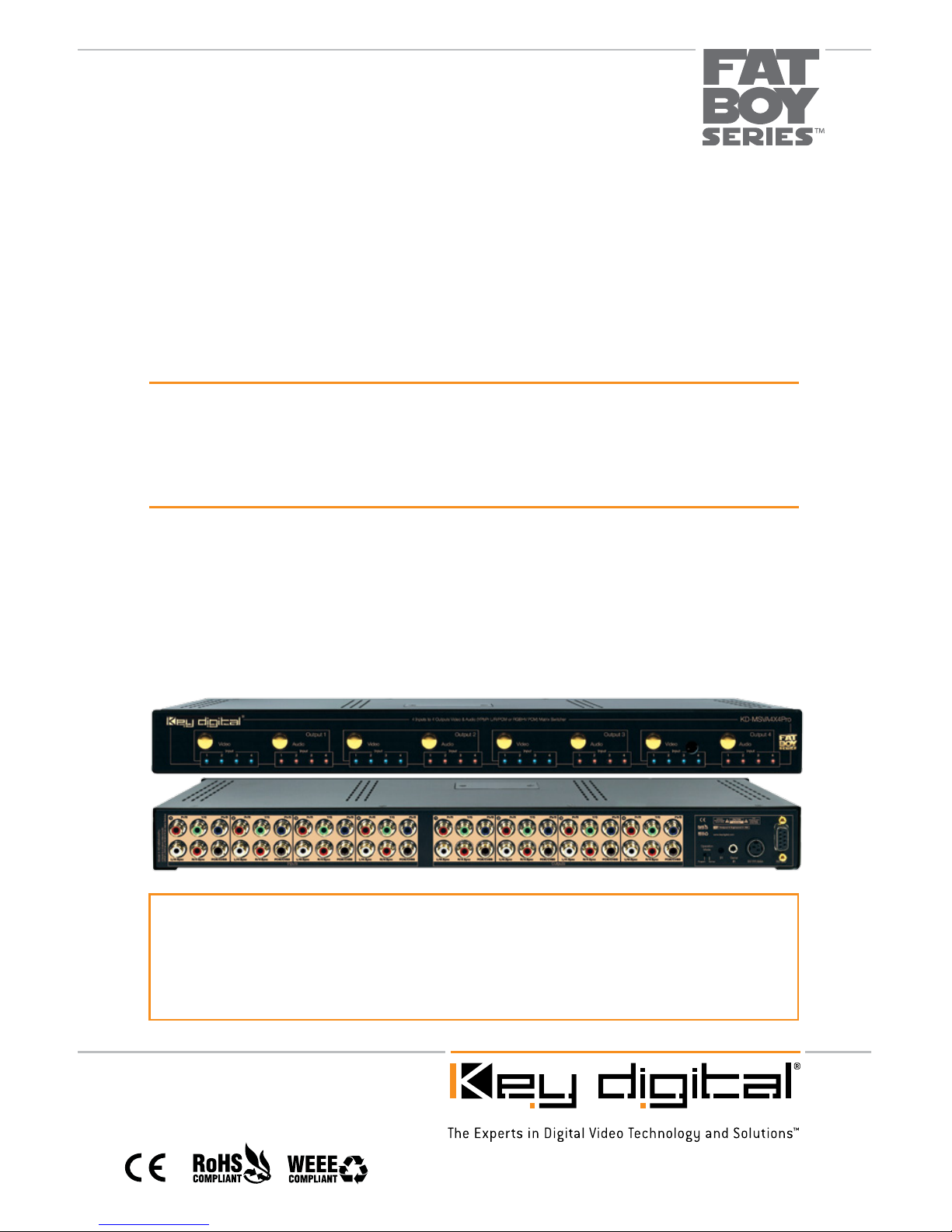
Key Digital® FAT BOY Series™ KD-MSVA4x4Pro is a Video/Audio Matrix Switcher capable
of separate switching of 4 Component (YPbPr) or RGBHV (VGA) Video Sources/Inputs to 4
independent Zones/Outputs with Analog and Digital Audio. Can also convert Analog Audio
to Digital Audio or Digital Audio to Analog Audio with full control over Volume, Bass, Treble,
Balance and Lip-Sync. Can also accept Composite Video over PCM connection.
KD-MSVA4X4Pro
Video Audio Matrix Switcher capable of switching up to 4 Component
(YPbPr) or RGBHV (VGA) Video Sources with L&R Analog or Digital
PCM Audio Sources/Inputs to 4 Independent Zones/Outputs
Set Up Guide
Page 2

Page 2
Table of Contents
About KD-MSVA4X4Pro
Connections, LEDs and Button Map . . . . . . . . . . . . . . . . . . . . . . . . . . . . . . . . . . . . . . . . . . . . . 3
Application Example . . . . . . . . . . . . . . . . . . . . . . . . . . . . . . . . . . . . . . . . . . . . . . . . . . . . . . . . . 5
Quick Setup Guide . . . . . . . . . . . . . . . . . . . . . . . . . . . . . . . . . . . . . . . . . . . . . . . . . . . . . . . . . . 6
Remote Control . . . . . . . . . . . . . . . . . . . . . . . . . . . . . . . . . . . . . . . . . . . . . . . . . . . . . . . . . . . .12
RS-232 Commands. . . . . . . . . . . . . . . . . . . . . . . . . . . . . . . . . . . . . . . . . . . . . . . . . . . . . . . . . .12
Specifications . . . . . . . . . . . . . . . . . . . . . . . . . . . . . . . . . . . . . . . . . . . . . . . . . . . . . . . . . . . . . .16
Important Product Warnings & Safety Instructions . . . . . . . . . . . . . . . . . . . . . . . . . . . . . . . . . . .18
How to Contact Key Digital
®
. . . . . . . . . . . . . . . . . . . . . . . . . . . . . . . . . . . . . . . . . . . . . . . . . . . .19
Warranty Information . . . . . . . . . . . . . . . . . . . . . . . . . . . . . . . . . . . . . . . . . . . . . . . . . . . . . . . . .19
About KD-MSVA4X4Pro
Description
» Video/Audio Matrix Switcher capable of separately switching up to 4 Component (YPbPr)
or RGBHV (VGA) Video Sources/Inputs to 4 independent Zones/Outputs with Analog and
Digital Audio
Key Features
» Full independent matrix switching of Video and Audio
» Supports all SD, HD, and VESA (VGA, SVGA, XGA, WXGA, SXGA, UXGA) resolutions
up to 1080p (60Hz & 50Hz)
» SD & HD: 480i, 480p, 720p, 1080i, 1080p
» VESA / VGA (RGBHV): From 640x480p up to 1920x1200p
» Inputs support L/R Analog and PCM Coaxial Digital Audio and can convert Analog to Digital
or Digital to Analog with full Audio control.
» Front LED’s indicate the selected Source and Input/Output status
» Independent Audio format configurations are supported at each output
© 2010 Key Digital, Inc. All rights reserved.
Page 3
Page 3
Key Benefits
» Independent or simultaneous muting of Video and Audio
» Capable of switching RGBHV signals by utilizing Left and Right Audio connections
for H & V signals
» Serial IR, Optical IR, Front Panel Control, Discrete Remote Codes, RS-232 Control.
» Supports major control systems such as AMX
®
, Control4®, Crestron®, RTI®, Savant,
Universal
®
, Xantech
®
Additional Key Features
» Easily controlled via IR remote (included), Serial IR, and RS-232
» RCA style connectors for ease of installation
» Slim 1U Rack chassis for space conservation
Matrix Expansion
» Can be incrementally expanded (with additional units) up to 4 Sources/Inputs to 32 Zones/
Outputs or 8 Sources/Inputs to 32 Zones/Outputs. Visit www.keydigital.com for expansion
unit model numbers
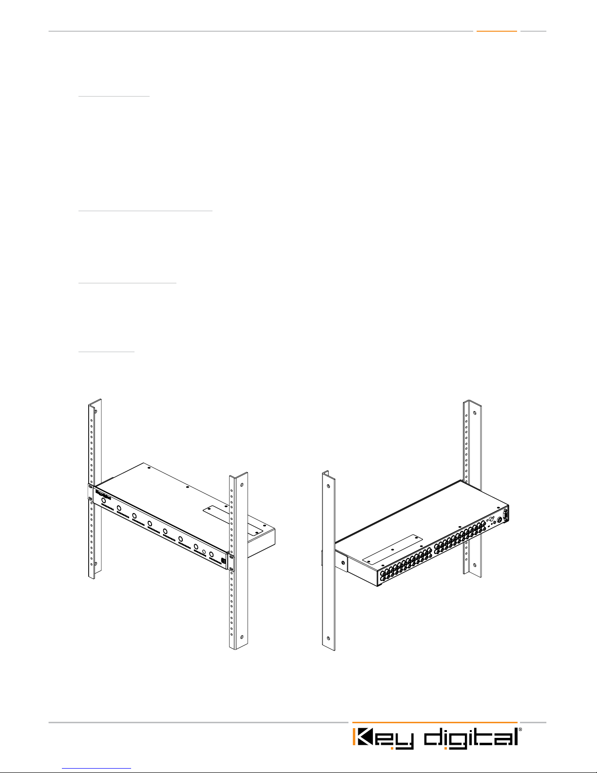
Mounting:
» Rack mount: Secure the rack ears to each side of the KD-MSVA4X4Pro with the supplied
hardware.Then, fasten the unit to the rack rails with the included machine screws.
Page 4

Page 4
Unit Configurations:
The KD-MSVA4X4Pro is a full matrix audio / video switcher capable of switching 4 Inputs to 4
Outputs. Any Input, or Source, is available to any Output, or Zone, at any time. The switcher can
also be used as a distribution amplifier when all outputs are fed from the same source input.
The unit will handle line level Analog audio signals and PCM Digital audio signals. It will also
convert Analog audio signals to Digital, and Digital audio signals to Analog. Full control of audio
properties such as Bass, Treble, Mid-range, Balance and Lip-Sync are also available. Control of the
KD-MSVA4X4Pro may be through Front Panel push buttons, IR Remote, Serial IR or RS-232.
The KD-MSVA4X4PRO can be configured to work in several Modes. There are 3 Audio Modes
available when in the RGBHV (VGA) mode and 5 Audio Modes available when in Component
(YPrPb) mode.
NOTE: These modes can only be set with the RS-232 command ‘SPC VT x’ to select the
Video Input format type desired, and ‘SPO xx T y’ to select the Audio Output type desired.
(See RS-232 commands detailed on page 14)
NOTE: The factory default configuration is Component Video with Audio Type #1.
½ RGBHV with Audio Type #1 - RGBHV Video with PCM Audio.
H&V will Input and Output over L&R connections. PCM Audio Input & Output at PCM. PCM
Audio will be in “pass-through” mode without audio processing or control. You may pass any
format of Digital audio through the PCM connections in this mode.
½ RGBHV with Audio Type #2 - RGBHV Video with Composite Video.
No Audio. H&V over L&R connections. Composite Video over PCM connections.
½ RGBHV with Audio Type #5 - RGBHV Video with PCM Audio.
H&V at L&R connections. PCM Audio at PCM connections. Full Audio processing and control
available. Will not pass encoded multichannel content. (Dolby Digital, DTS etc.)
½ Component with Audio Type #1 - Component Video with Analog L&R Audio.
Analog Audio inputs to Analog Audio outputs with full processing. PCM Audio inputs to PCM
outputs in “pass-through” mode. No audio processing. PCM will pass all audio formats.
½ Component with Audio Type #2 - Component Video with Analog L&R Audio.
Analog Audio inputs to Analog Audio outputs with full processing. Composite Video may be
switched utilizing the PCM inputs and outputs. No PCM audio available in this case.
½ Component with Audio Type #3 – Component Video with Analog L&R Audio.
Analog Audio inputs to Analog Audio outputs with full processing. Analog also converted to
PCM Audio at PCM Outputs. Full Audio processing at PCM Outputs. Will not pass encoded
multichannel content. (Dolby Digital, DTS etc.)
½ Component with Audio Type #4 - Component Video with PCM Audio.
PCM Inputs converted to Analog with full Audio processing to L&R Analog outputs. PCM Audio
also available at PCM Outputs via “pass-through” mode. No audio processing. PCM will pass all
audio formats.
½ Component with Audio Type #5 – Component Video with PCM Audio.
PCM Inputs converted to Analog with full Audio processing to PCM outputs. Will not pass
encoded multichannel content. (Dolby Digital, DTS etc.)
NOTE: Independent Audio format configurations are supported at each output.
Page 5
Page 5
Connections, LEDs and Button Map
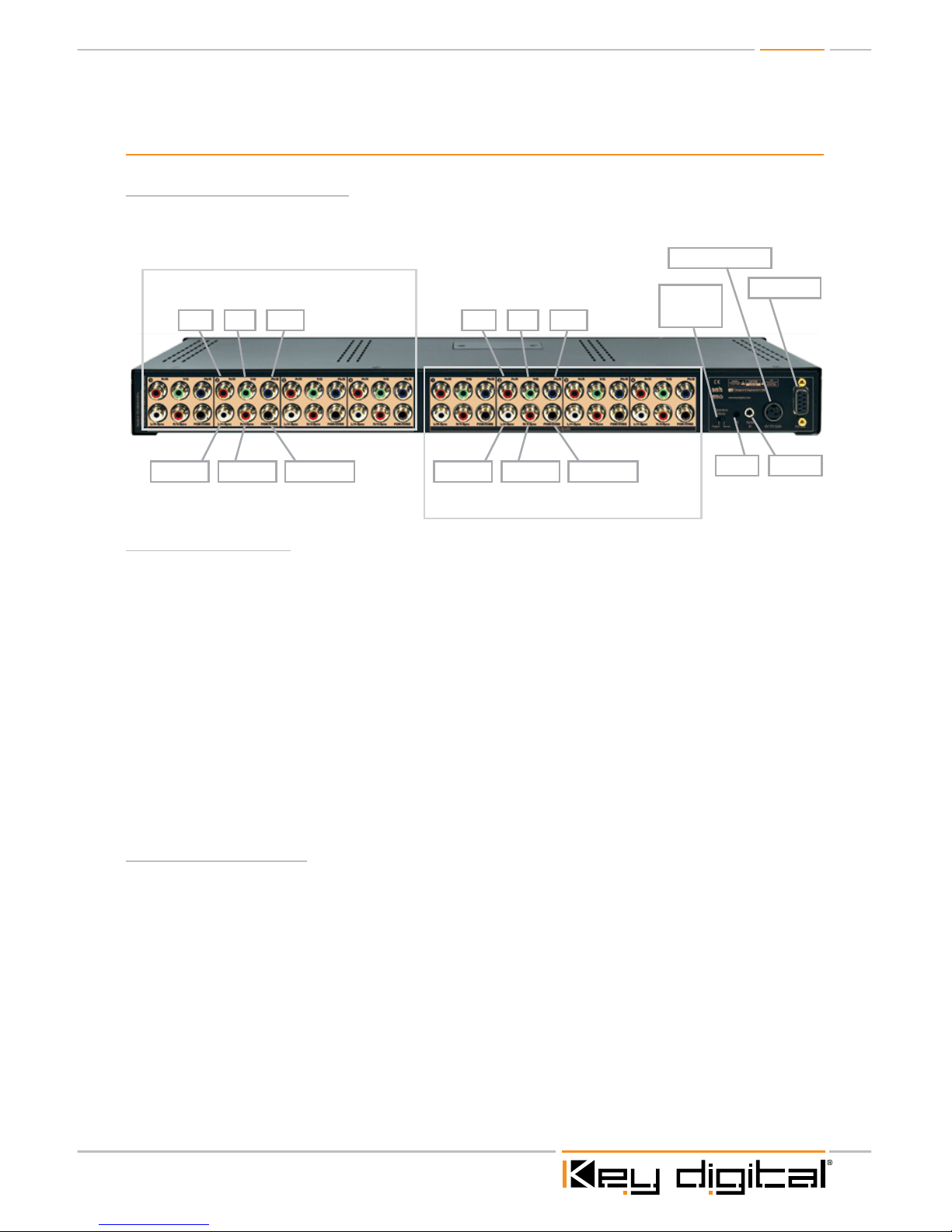
Rear Panel Connections:
All connections to the KD-MSVA4x4Pro are found on the rear panel of the unit. Refer to the
illustrations below for port assignments while making connections
Power Connection
Serial IRIR Eye
RS-232 Port
Operation
Mode
Switch
4X Video / Audio Inputs
4X Video / Audio Outputs
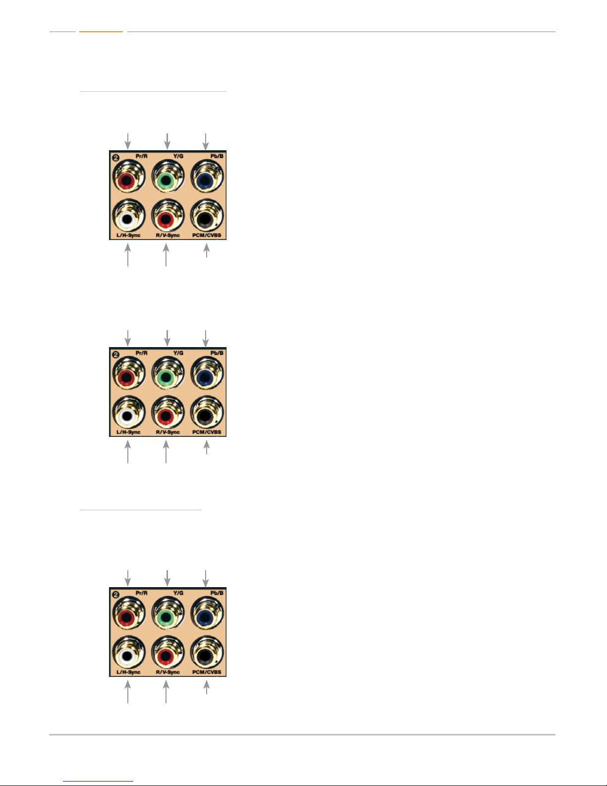
Pr/R Y/G Pb/B
L/H-Sync R/V-Sync PCM/CVBS
Pr/R Y/G Pb/B
L/H-Sync R/V-Sync PCM/CVBS
Input Connections
½ Component (YPbPr) Video Inputs
» Video Input YPbPr
» Audio Input
» L/R Analog
» PCM Digital Coaxial Audio
» Composite (CVBS) Video Input on PCM port (if not used)
½ RGBHV (VGA) Video Inputs
» Video Input RGBHV (utilizing L&R for H&V)
» Audio Input
» PCM Digital Coaxial Audio (only)
» Composite (CVBS) Video Input on PCM port (if not used)
Output Connections
½ Component (YPbPr) Video Outputs
» Video Output YPbPr
» Audio Output
» L/R Analog
» PCM Digital Coaxial Output
» Composite (CVBS) Video Output on PCM port (if not used)
½ RGBHV (VGA) Video Outputs
» Video Output RGBHV (utilizing L&R for H&V)
» Audio Output
» PCM Digital Coaxial Audio (only)
» Composite (CVBS) Video Output on PCM port (if not used)
Page 6
Page 6
Component Connections:
Input:
» (4X) Component (YPbPr) RCA connectors
» (4X) PCM (or Composite Video) RCA connectors
» (4X) Left & Right Analog Audio connectors
Output:
» (4X) Component (YPbPr) RCA connectors
» (4X) PCM (or Composite Video) RCA connectors
» (4X) Left & Right Analog Audio connectors
RGBHV Connections:
NOTE: If using a VGA (HD15) cable, you will need a VGA to 5 RCA breakout cable (not supplied)
Input:
» (4X) RGB RCA connectors
» (4X) PCM (or Composite Video) RCA connectors
» (4X) HV RCA connectors
Page 7

Page 7
Output:
» (4X) RGB RCA connectors
» (4X) PCM (or Composite Video) RCA connectors
» (4X) HV RCA connectors
Unit Connection Plate
½ Power Connection
½ Serial IR
½ Operation Mode Switch:
» 2 position slide switch to select Program
Mode for upgrading firmware
or Normal operation mode.
½ RS-232 Port
½ IR Eye
Page 8

Page 8
Front Panel Operation:
Output Video Select Button
Video Input LEDs
Output Audio Select Button
Audio Input LEDs
IR Eye
Buttons
½ Outputs 1-4; there are 2 buttons per Output, Video & Audio.
½ Press the Output buttons to select which Input is desired for that Output.
½ Each time an Output button is pressed, it will move sequentially to the next Input
» Output Video Select
» Cycle through to select desired Video Input
» Output Audio Select
» Cycle through to select desired Audio Input
LED Lights
LED Input Indicator Bank; Indicates selected Input for associated Output. There are 8 LED’s for
each Output number.
½ 4 Blue LED’s, 1 for each Video Input.
½ 4 Orange LED’s, 1 for each Audio Input
½ Each output has two push buttons to select the input source for both Video and Audio
separately for a total of 8 buttons.
» Output Video Mute
» LED lights 1 and 4 light to indicate Video Mute is enabled.
» Output Audio Mute
» LED lights 1 and 4 light to indicate Audio Mute is enabled.
Page 9

Page 9
Application Example
Component
Comp
L/R Audio
PCM Audio
L/R
Comp
L/R
Comp
L/R
Comp
L/R
Comp
L/R
PCM
Comp
L/R
PCM
Comp
L/R
PCM
Comp
L/R
PCM
PCM
PCM
PCM
PCM
Display
Projector
Distributed Audio System
Speakers
Display
Speakers
Display
SpeakersSpeakers
Blu-Ray
Cable Box
Satellite Box
DVD Player
KD-MSVA4X4Pro
RS232 Control
Serial IR
Optical IR
Optical IR
Zone 1
Zone 2 Zone 3 Zone 4
Page 10

Page 10
Quick Setup Guide:
Connections
1. Begin with the KD-MSVA4x4Pro and all Input/Output devices turned off and power cables
removed
2. Connect Component Video or RGBHV Video and Left / Right Analog or PCM Audio cables
into the appropriate Input/Output Connections
3. Connect your Video and Audio source devices.
4. Connect Video and Audio display devices.
5. Connect power to the KD-MSVA4x4Pro as well as all other input and output devices and turn
them on
6. Operate KD-MSVA4x4Pro switcher via the front panel buttons, IR remote, serial IR or RS-232
control
Operation:
After performing the setup above, the unit is ready for operation. Most applications will just involve
switching for day-to-day operation. There are several options for controlling the unit. Commands
can be issued via IR remote control, RS-232 or by using the front panel buttons.
Matrix Switching via Push Buttons
» Push “Output Video Select” button to cycle to desired Video Input source
» Push “Output Audio Select” button to cycle to desired Audio Input source
Matrix Switching via IR
» Video & Audio Switch
» To switch Video and Audio: Select the desired Output number, followed by the ‘R3’
button, then the desired Input number.
» Example. To switch Output 2 with Audio to Input 4 press; ’R1-02-R3-04’
Matrix Switching via RS-232
½ To switch Video Independently:
» SPOxxSIyy
» xx = Desired Video Output #
» yy = Desired Video Input #
½ To switch Audio Independently:
» SPOxxSAyy
» xx = Desired Audio Output #
» yy = Desired Audio Input #
½ To switch Video and Audio simultaneously:
» SPOxxSByy
» xx = Desired Video & Audio Output #
» yy = Desired Video & Audio Input #
Page 11

Page 11
Factory Default Reset:
To perform a factory default reset; with the unit powered on, press and hold the Output 1 Video
Select button AND the Output 4 Audio Select button simultaneously for 10 sec. then release. This
will reset the unit to its initial configuration. All customized settings will be lost.
Remote Control
The KD-MSVA4X4Pro ships with an IR remote control providing selection of inputs for every output.
As illustrated in the following diagram, these convenient keys are clearly marked.
Power On
Power OFF
R1 Button
R2 Button
R3 Button
All Mute / Mute
Balance
Tone Controls:
Bass, Middle,
Treble
LipSync (Delay)
All Restore / Restore
Arrow Up, Down
R4 Button
Volume
Numeric Keypad
Video Mode Audio Mode
Page 12

Page 12
KD-MSVA4x4Pro IR Remote Commands:
Below are listed some of the most common remote commands.
» Output Number = 01-04
» Input Number = 01-04
» Numeric Keypad Value = (00-99)
» Arrows Up/Down
» Power On = Power On
» Power Off = Power Off
» For a complete listing of all remote commands, please visit the Key Digital website at
www.keydigital.com
Switching and Mute Commands
Video & Audio Switch
To switch Video and Audio: press R1, Select the desired Output number followed by the ‘R3’
button, then the desired Input button. Example: To switch Output 2 to Input 4 press; ’’R1-02-R3-04’
Video Switch
» To switch Video ONLY: Select the desired Output number, followed by the ‘Video Mode’
button, then the desired Input number.
» Example: To switch Output 2 Video to Input 4 press; ’R1-02-VideoMode-04’
Audio Switch
» To switch Audio ONLY: Select the desired Output number, followed by the ‘Audio Mode’
button, then the desired Input number.
» Example: To switch Output 2 Audio to Input 4 press; ’R1-02-AudioMode-04’
Mute Video & Audio ALL
» To Mute both Video and Audio on ALL Outputs: Select ‘R1-All Mute’
Mute Video & Audio per Output Number
» To Mute both Video and Audio for a specific Output:
» Select ‘R1-(Output #)-Mute’
Mute Video ALL
» To Mute ALL Video Outputs: Select ‘R1-Video Mode – All Mute’
Mute Video per Output Number
» To Mute a specific Video Output: Select ‘R1-(Output #) – Video Mode - Mute’
Mute Audio ALL
» To Mute ALL Audio Outputs: Select ‘R1-Audio Mute – All Mute’
Mute Audio per Output Number
» To Mute a specific Audio Output: Select ‘R1-(Output #) – Audio Mode - Mute’
Un-Mute Video & Audio ALL
» To Un-Mute BOTH Video and Audio on ALL Outputs: Select ‘R1-All Restore’
Page 13

Page 13
Un-Mute Video ALL
» To Un-Mute ALL Video Outputs: Select ‘R1-Video Mode – All Restore’
Un-Mute Audio ALL
» To Un-Mute ALL Audio Outputs: Select ‘R1-Audio Mode – All Restore’
Audio Adjustment Commands
Output:
» Audio Output adjustment ranges:
» Volume = 00-96 (80 =default)
» Bass, Treble & Middle Frequencies =00-24 (12 = default)
» Balance = 00-40 (20 = default)
» Lip Sync (Delay) = 00-99 (00 = default) each increment = 5.5ms
Volume Default
» To return the Overall Output Volume for a specific Output number to the default setting:
Select the desired Output number, press the ‘Volume’ button, and then R3.
» Example: To return the Output Volume of Output 2 to the default setting, press; ’R1-02-
Volume-R3’
Volume Level
» To adjust the Output Volume for a specific Output number: Select the desired Output
number, press the ‘Volume’ button, and then enter the Value desired. You may also use the
Up or Down Arrow button to increase or decrease the Volume.
» Example: To set the Volume level of Output 2 to 40, press; ’R1-02-Volume-40’
» Example: To increase or decrease the Volume level of Output 2, press;
‘R1-02-Volume-▲’ to increase and ‘R1-02-Volume-▼’ to decrease.
IR Extender:
You may also want to use an IR extender, such as the KD-IRKIT300: A rear panel sensor is available
for use with the IR extender. A wired IR serial connector is also provided. Mount the IR extender on
the side of the KD-MSVA4X4Pro unit, or connect the serial connector cable.
Connecting Block
KD-IRCB204
KD-IRB3099
Back of the Unit
Wired IR Extender
3.5mm male-to-male
mono cable
Wired IR Extender KD-IRB3099 Unit Uses a 3.5mm male-to-male Mono cable
Page 14

Page 14
RS-232 Commands:
The KD-MSVA4X4Pro provides access to all functions when used with an RS-232 control system.
For a complete list of all available RS-232 commands please see the “Technical” section at www.
keydigital.com.
Connection protocol is as follows:
» Baud rate: 57,600
» Data Bits: 8
» Parity: None
» Stop Bits: 1
» Flow Control: None
Pin 5 – Ground
Pin 3 – Receive
Pin 2 – Transmit
RS-232 cable pin out
The commands are not case sensitive. The command lines are shown with spaces for clarity. No
spaces are required when entering commands.
All standalone units have ‘00’ as their default address. When multiple units are used as in an
expansion configuration, each unit will have a unique address. In this case, all below commands
should start with the Prefix: ‘A zz’ , where zz = [01-99] and represents the units System Address.
This will ensure the commands are sent to the correct unit.
Values for Commands:
Address zz = 00-99 (Default standalone 4x4 is 00)
Inputs xx = 01-99 (or A = All)
Outputs xx = 01-99 (or A = All)
Output Volume yy = 00-96 (Default is 80)
Output Bass yy = 00-24 (Default is 12)
Output Middle yy = 00-24 (Default is 12)
Output Treble yy = 00-24 (Default is 12)
Output Balance yy = 00-40 (Default is 20)
Output Delay yy = 00-99 (Default is 00, each increment = 5.5ms)
Output Mute Interval yy = 00-09 (Default is 00)
H Help
PHI Help with Input Setup Commands
PHO Help with Output Setup Commands
PHC Help with Control Setup Commands
PHT Help with Status Commands
PN Power On
PF Power Off
Page 15

Page 15
System Output Set-Up Commands
To set Video Configuration Type:
» ‘SP C VT x’ To set the Video Input Format Type:
» Where x = ‘0’ or ‘1’ and is the Video Type desired.
» ‘0’ = Component (YPbPr), ‘1’ = RGBHV (VGA)
» Example: To set the Video Input format type to RGBHV, issue the command; ‘SPCVT1’
To set Audio Configuration Type:
» ‘SP O xx T y’ To set the Audio Output Format Type:
» Where xx = ‘01-99’ and is the Output number and y = ‘1-5’ and is the Configuration Type
desired.
» Example: To set Audio Type to 2 for Output 2, issue the command; ‘SPO02T2’
» Example: To set Audio Type to 1 for Output 3, issue the command; ‘SPO03T1’
» Example: To set Audio Type to 4 for All Outputs, issue the command; ‘SPOAT4’
Audio Configuration types listed below.
Audio Type #1 - Analog L&R Audio
» Full Audio processing and control at analog outputs. PCM Audio Output from PCM Inputs
with PCM Audio in “pass-through” mode without audio processing or control. You may pass
any format of Digital audio through the PCM connections in this mode.
Audio Type #2 - Analog L&R Audio.
» Analog Audio inputs to Analog Audio outputs with full processing.
Audio Type #3 – Analog L&R Audio.
» Analog Audio inputs to Analog Audio outputs with full processing. Analog also converted to
PCM Audio at PCM Outputs. Full Audio processing at PCM Outputs. Will not pass encoded
multichannel content. (Dolby Digital, DTS etc.)
Audio Type #4 - PCM Audio.
» PCM Inputs converted to Analog with full Audio processing to L&R Analog Outputs.
PCM Audio also available at PCM Outputs via “pass-through” mode. No audio processing.
PCM will pass all audio formats.
Audio Type #5 – PCM Audio.
» PCM Inputs converted to Analog with full Audio processing to PCM outputs. Will not pass
encoded multichannel content. (Dolby Digital, DTS etc.)
To set Audio Output Volume:
» ‘SP O xx AV yy’ To set the Output Volume level:
» Where xx = ‘01-99’ and is the Output number and yy = ‘00-99’ and is the Volume level.
» Example: To set Audio Volume of Output 3 to 50, issue the command; ‘SPO03AV50’
Page 16

Page 16
To Mute Output - Analog Audio Only:
» ‘SP O xx A E/D/T’ To Mute the Analog Audio Output for a specific Output:
» Where xx = ‘01-99’ and is the Output number and ‘E’ is for Audio Mute Enabled, ‘D’ is for
Audio Mute Disabled and ‘T’ is to toggle between Enabled and Disabled.
» Example: To Enable Audio Mute for Output 3, issue the command; ‘SPO03AE’
To Mute Output - PCM Audio Only:
» ‘SP O xx PM E/D/T’ To Mute the PCM audio for a specific output;
» Where xx = ‘01-99’ and is the Output number, and ‘E’ is for Audio Mute Enabled, ‘D’ is for
Audio Mute Disabled and ‘T’ is to Toggle between Enabled and Disabled.
» Example: To Enable PCM Audio Mute for Output 3, issue the command; ‘SPO03PME’
» NOTE: This command will also mute Composite Video if utilized at the PCM connections
To Mute Output – Video & Audio:
» ‘SP O xx AVM E/D/T’ To Mute the Video & Audio Output for a specific Output;
» Where xx = ‘01-99’ and is the Output number and ‘E’ is for Video & Audio Mute Enabled, ‘D’
is for Video & Audio Mute Disabled and ‘T’ is to toggle between Enabled and Disabled.
» Example: To Enable Video & Audio Mute for Output 3, issue the command; ‘SPO03AVME’
To switch Video and Audio together:
» ‘SP O xx S yy’ To rout the desired Input to the desired Output with Audio:
» Where xx = ‘01-99’ and is the Output number and yy = ‘01-99’ and is the Input number.
» Example: To route Input 3 with audio to Output 2 issue the command; ‘SPO02S03’
To switch Video only:
» ‘SP O xx SI yy’ To rout the desired Video Only Input to the desired Output:
» Where xx = 01-99 and is the Output number and yy = 01-99 and is the Input number.
» Example: To route Input 3 to Output 2 issue the command; ‘SPO02SI03’
To switch Audio only:
» ‘SP O xx SA yy’ To rout the desired Audio Only Input to the desired Output:
» Where xx = 01-99 and is the Output number and yy = 01-99 and is the Input number
» Example: To route Audio Input 3 to Output 2 issue the command; ‘SPO02SA03’
To switch PCM Audio (or CV) Only:
» ‘SP O xx SP yy’ To rout the desired PCM Audio (or Composite Video) to the desired Output:
» Where xx = ‘01-99’ and is the Output number, and yy = ‘01-99’ and is the Input number.
» Example: To route PCM from Input 3 to Output 2, issue the command; ‘SPO02SP03’
System Control Set-Up Commands
Front Panel Buttons:
» ‘SP C FB E/D/T’ To Enable or Disable the Front Panel push buttons for the unit;
» Example: To Enable the front panel buttons issue the command; ‘SPCFBE
» Example: To Disable the front panel push buttons issue the command; ‘SPCFBD’
» Example: To Toggle between front panel buttons enable-disable issue the
command ‘SPCFBT’
Page 17

Page 17
To Reset Unit to factory default settings:
» ‘SP C DF’
» Example: To reset the unit to factory default, issue the command line: ‘SPCDF’
System Status Commands
Global Status:
» ‘ST A’
» Example: To issue a query for the current status of all parameters,
issue the command: ‘STA’
Key Digital provides a resource database for downloadable control modules at:
www.keydigital.com/controlmain.aspx
Accessories:
» External 6 Volt DC 6.6 Amp switching power supply (for 110V-240V 50/60Hz applications)
» IR Remote control with two batteries
» Operating Instructions
Specifications
Technical:
» Input (Each): Component (YPbPr) on 3 RCA female 1Vpp/75Ω; 1 Composite Video
or SPDIF on 1 RCA female 1Vpp/75Ω. Left and Right Analog Line Audio on two RCA
connectors(2VRMS/10kohm)
» Input (Each): RGBHV (VGA) on 5 RCA female RGB 1Vpp/75 Ω, HV 5V TTL (Using Left
Audio connector for ‘H’, Right Audio connector for ‘V’); 1 Composite Video or SPDIF on
1 RCA female 1Vpp/75Ω.
» Output (Each): Component (YPbPr) on 3 RCA female 1Vpp / 75Ω; 1 Composite Video or
SPDIF on 1 RCA female 1Vpp/75Ω. Left and Right Analog Line Audio on two RCA connectors
(2VRMS/10kohm)
» Output (Each): RGBHV (VGA) on 5 RCA female RGB 1Vpp/75 Ω, HV 5V TTL (Using Left
Audio connector for ‘H’, Right Audio connector for ‘V’); 1 Composite Video or SPDIF on
1 RCA female 1Vpp/75Ω.
» Max Video Input Level: YPbPr: 1.2Vpp on 75Ω, AC coupling; Composite Video or S/PDIF:
1.2Vpp on 75Ω, AC coupling
» Return Loss: -19dB
» Max Video Output Level: YPbPr: 1.5Vpp on 75Ω, DC coupling; Composite Video or
S/PDIF: 1.2Vpp on 75Ω, AC coupling; RGBHV video supports up to 1920x1200 resolution
(VESA format) WUXGA
» Control: Front panel push buttons and LED’s, front and rear Infrared Receiver, Wired IR on
rear, RS-232 on Tx and Rx lines
» Matrix Switching: Full independent matrix switching of Video and Audio
» Video S/N Ratio: 58dB RMS un-weighted; 65 dB RMS @ 5MHz weighted, optimal EQ
Page 18

Page 18
» K-Factor: 0.22% @ optimal EQ
» Video Isolation (Crosstalk): -45dB @ 5MHz; Supports Normal(up to 96kHz, does not
accept Dolby D, DTS) mode with Audio Control or Bypass mode(accepts any digital audio
Dolby D, DTS etc.) in PCM
» Resolution Conversion: 24 bits; 48kHz sampling rate for Analog Stereo Audio
» Analog Audio Max Input Level: 4dBu on 50kΩ, AC coupling
» Analog Audio Max Output Level: 4dBu on 150kΩ, DC coupling
» Audio Bandwidth: 20Hz to 20kHz @ 0dBu
» TND + Noise: 0.33% @0dBu @ 1kHz
» S/PDIF Max Input Level: 1Vpp on 75Ω, AC coupling
» S/PDIF Max Output Level: 1Vpp on 75Ω, DC coupling
» Audio Rates: Supports both RS232 (Baud Rate at 57600bps) and Serial IR (at 38kHz)
» Control Connections: DB9 connector for RS232; Two (2) IR receive sensors at Front and
Rear for Remote Control; 3.5mm Mono Phone Jack for Serial IR (input only)
» Power: +6V, 6.6A
General:
» Regulation: CE, RoHS, WEEE
» Rack Mount: 1U, 1 Rack Width (rack ears included)
» Enclosure: Black Metal
» Product Dimensions: L = 17.5” W = 7” H = 1.75”
» Shipping Carton Dimensions: L = 23.5” W = 11” H = 4.5”
» Product Weight: 6 lb
» Shipping Weight: 9 lb
» Accessories: IR Remote, UL Certified Power Supply
Important Product Warnings:
1. Connect all cables before providing power to the unit.
2. Test for proper operation before securing unit behind walls or in hard to access spaces.
3. If installing the unit into wall or mounting bracket into sheet-rock, provide proper screw support
with bolts or sheet-rock anchors.
Safety Instructions.
Please be sure to follow these instructions for safe operation of your unit.
1. Read and follow all instructions.
2. Heed all warnings.
3. Do not use this device near water.
4. Clean only with dry cloth.
Page 19

Page 19
5. Install in accordance with the manufacturer’s instructions.
6. Do not install near any heat sources such as radiators, heat registers, stoves, or other
apparatus (including amplifiers) that produce heat.
7. Only use attachments/accessories specified by the manufacturer.
8. Refer all servicing to qualified service personnel. Servicing is required when the device has
been damaged in any way including:
» Damage to the power supply or power plug
» Exposure to rain or moisture
You MUST use the Power Supply provided with your unit or you VOID
the Key Digital
®
Warranty and risk damage to your unit and associated equipment.
How to Contact Key Digital
®
System Design Group (SDG)
For system design questions please contact us at:
½ Phone: 914-667-9700
½ E-mail: sdg@keydigital.com
Technical Support
For technical questions about using Key Digital® products, please contact us at:
½ Phone: 914-667-9700
½ E-mail: tech@keydigital.com
Repairs and Warranty Service
Should your product require warranty service or repair, please obtain a Key Digital® Return Material
Authorization (RMA) number by contacting us at:
½ Phone: 914-667-9700
½ E-mail: rma@keydigital.com
Feedback
Please email any comments/questions about the manual to:
½ E-mail: customersupport@keydigital.com
Warranty Information
All Key Digital® products are built to high manufacturing standards and should provide years of
trouble-free operation. They are backed by a limited two-year parts and labor warranty.
Page 20

521 East 3rd Street, Mount Vernon, NY 10553
Phone :: 914.667.9700 Fax :: 914.668.8666
Web :: www.keydigital.com
Key Digital®, led by digital video pioneer Mike Tsinberg,
develops and manufactures high quality, cutting-edge
technology solutions for virtually all applications where
high quality video imaging is important. Key Digital
®
is at the forefront of the video industry for Home
Theater Retailers, Custom Installers, System Integrators,
Broadcasters, Manufacturers, and Consumers.
Rev 0 – Jan. 2011
 Loading...