

Page 1
521 East 3rd Street, Mount Vernon, NY 10553
Phone :: 914.667.9700 Fax :: 914.668.8666
Web :: www.keydigital.com
KD-MSA8X8 Operating Instructions
Key Digital®, led by digital video pioneer Mike Tsinberg,
develops and manufactures high quality, cutting-edge
technology solutions for virtually all applications where
high quality video imaging is important. Key Digital®
is at the forefront of the video industry for Home
Theater Retailers, Custom Installers, System Integrators,
Broadcasters, Manufacturers, and Consumers. We
provide
total video system solutions because we
know and help drive the technology, the industry, the
business, and all the latest up-and-coming standards.
But most of all, we know exactly what you need for your
unique application - the right solution.
Rev 0 – Sept. 2007
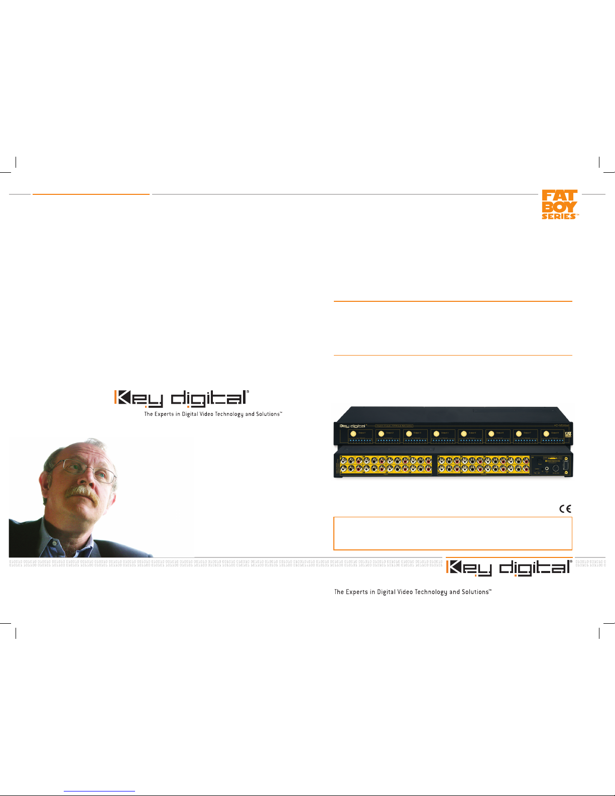
The KD-MSA8X8 is a full matrix audio switcher capable of integrating up to 8 inputs or
sources with 8 outputs or zones. The unit directly accepts analog and PCM digital audio
signals and is capable of switching all popular encoded (AC3, DTS etc.) signals as well.
Operating Instructions
KD-MSA8X8
Audio Matrix Switcher capable of switching up to
8 L/R/Digital PCM Audio Sources/Inputs to
8 independent Zones/Outputs
KD-MSA8x8_Manual.indd 2-1 9/4/07 12:22:25 PM
Page 2
KD-MSA8X8 Operating Instructions
Page 2
KD-MSA8X8 Operating Instructions
Page 1
Table of Contents
Introduction
About the KD-MSA8X8. . . . . . . . . . . . . . . . . . . . . . . . . . . . . . . . . . . . . . . . . . . . . . . 2
Audio Connections . . . . . . . . . . . . . . . . . . . . . . . . . . . . . . . . . . . . . . . . . . . . . . . . . . 2
Additional Key Features. . . . . . . . . . . . . . . . . . . . . . . . . . . . . . . . . . . . . . . . . . . . . . . 2
Accessories . . . . . . . . . . . . . . . . . . . . . . . . . . . . . . . . . . . . . . . . . . . . . . . . . . . . . . . 2
Installation and Operation
Mounting . . . . . . . . . . . . . . . . . . . . . . . . . . . . . . . . . . . . . . . . . . . . . . . . . . . . . . . . . 3
Rear Panel Connections . . . . . . . . . . . . . . . . . . . . . . . . . . . . . . . . . . . . . . . . . . . . . . 3
Front Panel Features . . . . . . . . . . . . . . . . . . . . . . . . . . . . . . . . . . . . . . . . . . . . . . . . . 5
Operation . . . . . . . . . . . . . . . . . . . . . . . . . . . . . . . . . . . . . . . . . . . . . . . . . . . . . . . . . 6
Front Panel Control . . . . . . . . . . . . . . . . . . . . . . . . . . . . . . . . . . . . . . . . . . . . . . 6
IR (Remote Control). . . . . . . . . . . . . . . . . . . . . . . . . . . . . . . . . . . . . . . . . . . . . . 9
RS-232 Control. . . . . . . . . . . . . . . . . . . . . . . . . . . . . . . . . . . . . . . . . . . . . . . . .10
RS-232 Codes for KD-MSA8X8 . . . . . . . . . . . . . . . . . . . . . . . . . . . . . . . . . . . .10
Firmware Update Procedure . . . . . . . . . . . . . . . . . . . . . . . . . . . . . . . . . . . . . . . . . . . . . . . . . . . 11
Mechanical . . . . . . . . . . . . . . . . . . . . . . . . . . . . . . . . . . . . . . . . . . . . . . . . . . . . . . . . . . . . . . . .12
Important Safety Instructions . . . . . . . . . . . . . . . . . . . . . . . . . . . . . . . . . . . . . . . . . . . . . . . . . . .12
How to Contact Key Digital®. . . . . . . . . . . . . . . . . . . . . . . . . . . . . . . . . . . . . . . . . . . . . . . . . . . .13
Warranty . . . . . . . . . . . . . . . . . . . . . . . . . . . . . . . . . . . . . . . . . . . . . . . . . . . . . . . . . . . . . . . . . .13
© 2007 Key Digital, Inc. All rights reser ved.
Always follow the instructions provided in this Operating Manual.
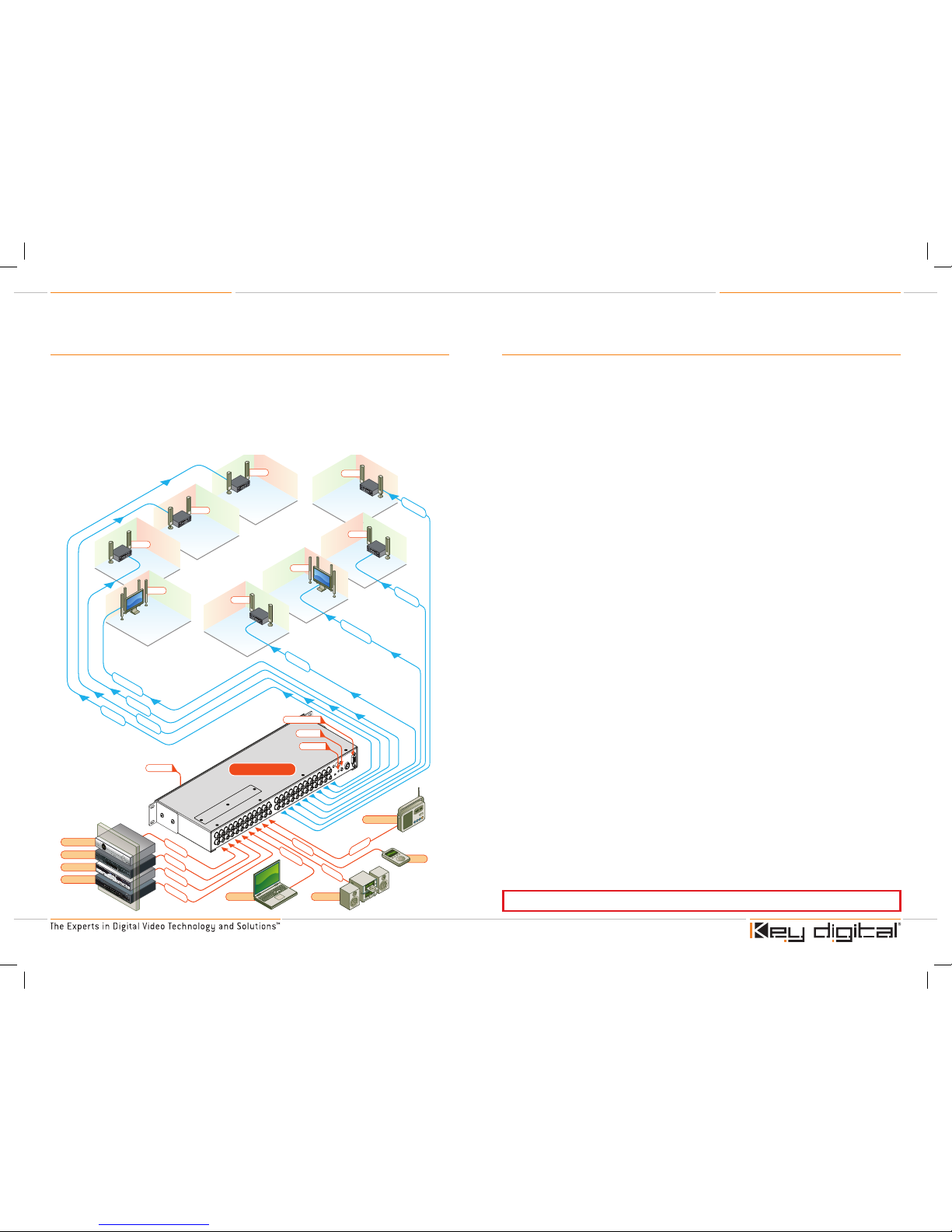
Quick Setup Guide
Begin with the KD-MSA8X8 and all input/output devices turned off
with power cables removed
Connect audio sources to appropriate input ports on the KD-MSA8X8
Connect audio outputs to amplifier, display or other receiving device
Connect power to the KD-MSA8X8 as well as all other input and output
devices and turn them on
Operate KD-MSA8X8 switcher via front panel buttons, IR remote, serial IR or RS-232 control
1.
2.
3.
4.
5.
L/R + PC
M
L/R + PC
M
L/R + PCM
L/R + PC
M
L/R
Audio
L/R
Audio
L/R
Audio
L/
R
A
udi
o
DVD Player
Cable TV
Sat. Radio
CD Player
Computer
CD Player
AM/FM Tuner
iPod
L/R
Audi
o
L/R
Audi
o
L/R
Audi
o
L/R
Audi
o
L/
R
Audi
o
L/R
Audi
o
5.
1
Sur
roun
d
5.
1
Sur
roun
d
RS232 Control
Optical IR
Optical IR
KD-MSA8X8
Serial IR
Zone 4
Zone 5
Zone 6
Zone 7
Zone 8
Zone 3
Zone 2
Zone 1
KD-MSA8x8_Manual.indd 2-1 9/4/07 12:22:32 PM
Page 3
KD-MSA8X8 Operating Instructions
Page 2
KD-MSA8X8 Operating Instructions
Page 3
Introduction
About the KD-MSA8X8
The KD-MSA8X8 is a full matrix audio switcher capable of switching 8 inputs to 8 outputs. The
idea behind a full matrix switcher is the fact that any input, or source, is available on any output,
or zone, at any time. Likewise, the switcher can also be used as a distribution amplifier when all
outputs are fed from the same source input.
The unit will line level analog audio signals and PCM digital audio signals. Multi-channel surround
signals such as 5.1 are also accommodated by using two inputs and two outputs for every source
and zone (see page 4). This yields the capability of switching 4 inputs to 4 outputs. There is no
‘conversion’ process, therefore analog input yields analog output, digital input yields digital output
and encoded signals are passed through the unit without decoding.
Control of the KD-MSA8X8 is through front panel push buttons, IR remote, serial IR or RS-232.
Audio Connections:
Input
Analog: Stereo line level
(8) [RCA style connectors]
-orMulti-channel analog surround*
(4) [RCA style connectors]
Digital: PCM coaxial digital audio**
(8) [RCA style connectors]
* Multi-channel analog surround signals accommodated using two input ports and two output ports, thereby creating a
4X4 surround matrix switcher.
**The digital audio path can also pass encoded signals such as AC3, DTS, etc….
Additional Key Features:
Front panel LED input/output assignment confirmation
Easily controlled via IR remote (included) with discrete codes, Serial IR, and RS-232
RCA style connectors for ease of installation
Slim 1U Rack chassis for space conservation
Accessories
External 6 Volt DC 6.6 Amp switching power supply (for 110V-240V 50/60Hz applications)
IR Remote control with two batteries
Operating Instructions
›
›
›
›
›
›
›
Output
Analog: Stereo line level
(8) [RCA style connectors]
-orMulti-channel analog surround*
(4) [RCA style connectors]
Digital: PCM coaxial digital audio**
(8) [RCA style connectors]
INSTALLATION AND OPERATION
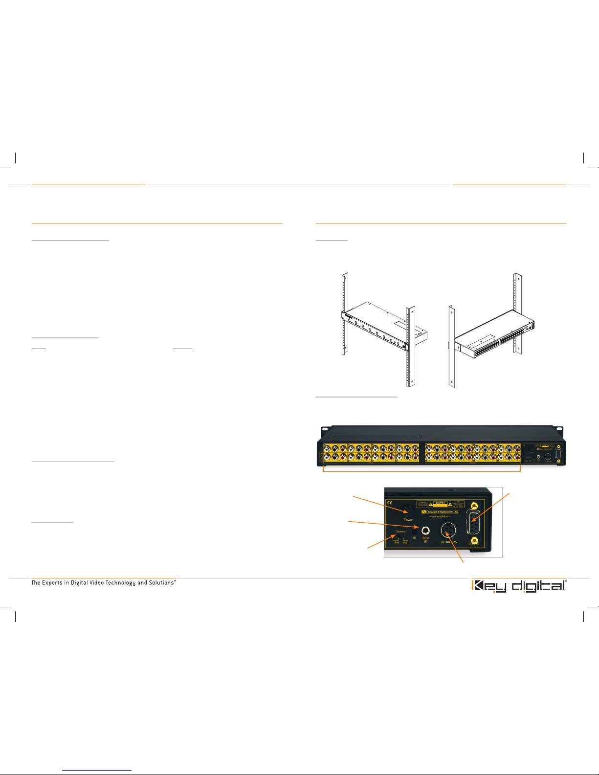
Mounting
Rack mount: Secure the rack ears to each side of the KD-MSA8X8 with the supplied hardware.
Then, fasten the unit to the rack rails with the included machine screws.
Figure 2: Rack mounting the KD-MSA8X8
Rear Panel Connections
All connections to the KD-MSA8X8 are found on the rear panel of the unit. Refer to the drawing
below for port assignments while making connections.
2. Power Button
3. IR eye and
serial IR port
5. Power Connections
4. Programming Switch
6. RS-232 Connector
1. Audio Inputs
Figure 3
KD-MSA8x8_Manual.indd 2-3 9/4/07 12:22:37 PM
Page 4

KD-MSA8X8 Operating Instructions
Page 4
KD-MSA8X8 Operating Instructions
Page 5
1. Audio Inputs:
a. Connect sources equipped with line level analog audio outputs to analog inputs 1-8.
Make sure to connect each cable (L/R) to the corresponding port (L=white/R=red) on the KDMSA8X8
b. Connect sources equipped with coaxial digital audio outputs to digital inputs 1-8. These
inputs are black and labeled ‘PCM’
c. For multi-channel analog surround (5.1) usage, connect inputs and outputs as follows:
i. L = White ‘L’ port on input 1,3,5 or 9 and output 1,3,5 or 9
ii. C = Black ‘PCM’ port on input 1,3,5 or 9 and output 1,3,5 or 9
iii. R = Red ‘R’ port on input 1,3,5 or 9 and output 1,3,5 or 9
iv. LS = White ‘L’ port on input 2,4,6 or 8 and output 2,4,6 or 8
v. Sub = Black ‘PCM’ port on input 2,4,6 or 8 and output 2,4,6 or 8
vi. RS = Red ‘R’ port on input 2,4,6 or 8 and output 2,4,6 or 8
2. Power Button
3. IR eye and serial IR port
a. IR eye on the rear panel is identical to that on the front of the unit and can be used with a
flasher or the supplied IR remote. It offers a convenient way to conceal unsightly IR flashers.
b. The serial IR port can be used with serial IR control systems.
4. Programming switch:
a. This is used to switch between programming mode (for updating the unit’s firmware) and
normal operation. See page 11.
5. Power Connection
6. RS-232 Connector:
a. This connector has two functions. It serves as a serial communication port for
connection to RS-232 based control systems and also for firmware updates via serial
connection to a standard PC. See page 8 for RS-232 control protocol and page 11 for
firmware update procedure.
➔
➔
➔
»
»
»
»
»
»
➔
➔
➔
➔
Front Panel Features
1. Input select button
a. Press this button to cycle through inputs sequentially from 1-8.
2. LED Input Indicator Bank
a. Indicates selected input port for associated output
3. IR eye
a. The IR eye on the front panel receives commands from IR remote controls or IR
flashers. Note that an identical IR eye is also available on the rear panel. When IR control is
enabled (factory default, though this can be disabled via RS-232. See page 8), both eyes are
concurrently active.
After all audio connections are made on the rear panel of the KD-MSA8X8 as described on
page 4, connect the supplied power adapter. Lastly, apply power to all other sources and
displays or destinations.
➔
➔
➔
2. LED Input Indicator Bank
1. Input Select Buttons
3. IR eye
CAUTION: When installing the unit, make all audio connections before plugging
in the external power supply provided with your unit. Do NOT apply power to the
unit until all audio connections have been made to your KD-MSA8X8 unit from
the “source” devices to the display(s) and/or devices. You MUST use the external
power supply provided with your unit or you VOID the Key Digital® Warranty and
risk damage to your unit and associated equipment.
Figure 4
KD-MSA8x8_Manual.indd 4-5 9/4/07 12:22:39 PM
Page 5

KD-MSA8X8 Operating Instructions
Page 6
KD-MSA8X8 Operating Instructions
Page 7
Operation
After performing the setup above, the unit is ready for operation. When the unit is initially powered
on all LED indicators are off until either:
An RS-232 command is issued
IR power on is issued
Any front panel button is pressed
Most applications will involve only input switching for day-to-day operation. There are a several
options for controlling the unit. Commands can be issued via IR remote control, RS-232 or simply
by using the front panel buttons. Keep in mind that controlling the unit in a 4 input/4 output multichannel analog surround setup requires concurrent switching of two inputs and two outputs for
each input source and output zone.
Front Panel Control
For switching inputs, simply press the ‘Input Select’ button within the desired output section. See
number 1 on Figure 4. Pressing this button repeatedly will cycle through all audio inputs.
IR (Remote Control)
The KD-MSA8X8 ships with an IR remote control providing selection of inputs for every output. As
illustrated in the following diagram, these convenient keys are clearly marked.
To issue a command via IR to switch inputs, issue the following sequence:
1. First, press the button labeled ‘R1’
2. Next, press the buttons for the unit’s address [00-99]. Factory default is 00
> When multiple units are used in a system, unique unit addresses allow for error free switching,
ensuring that only the addressed unit ‘listens’ to the command issued. This is especially
helpful in IR control situations.
3. Then, press the ‘Output Select’ rocker style button up or down to select the desired output to
switch. Note that the LED’s will flash, indicating selected output.
4. Next, press the ‘Input Select’ rocker style button up or down to select the desired input. Note
that the LED’s will indicate selected input.
5. Finally, press the ‘R1’ button to complete the sequence. Note that the LED indicators will flash
for 30 seconds or until ‘R1’ is pressed. Whenever the LED’s are flashing, the status of that
output can be switched and no other output can be changed. To end one sequence and begin
another, press ‘R1’ or wait 30 seconds for LED’s to stop flashing.
Alternatively, the output and input selection in steps 3 and 4 above can be made in the
following manner.
3. Press the number keypad buttons [01~08] to select the desired output to switch. Note that the
LED’s will flash, indicating selected output.
4. Then, press the number keypad buttons [01~08] to select the desired input. Note that the LED’s
will change, indicating selected input.
For all IR commands, the steps 1 and 2 above must be issued fir st to address the unit.
See the following button labels for IR commands.
›
›
›
IR Extender
You may also want to use an IR extender, such as available by Xantech:
A rear panel sensor is perfect for use with Xantech IR extender
A wired IR serial connector is also provided
You’ll need to either mount the IR extender on the side of the KD-MSA8X8 unit,
or connect the serial connector cable.
›
›
Figure 5: IR Remote Buttons
www.keydigital.com
1
2 3
4
5 6
7
8 9
0
Power ON
Power OFF
Input
Select
Output
Select
Mute
Channel
Restore
Channel
Mute
All
Restore
All
R1 R2 R3
R6R5 R7R4R8
1
2 3
4
5 6
7
8 9
0
Power ON
Power OFF
Input
Select
Output
Select
www.keydigital.com
Mute
Channel
Restore
Channel
Mute
All
Restore
All
R1 R2 R3
R6R5 R7R4R8
Power On and
Off buttons
Numeric Keypad
See steps 3 and 4 above
Input Select button
Issue the unit address and
select output (see steps
1-3 above), then press this
rocker type switch up or
down to select desired input
R1 Button
Press this button
to begin the unit
address command.
See step 1 above
Wired IR Extender KD-MSA8X8 Unit
3.5mm male-to-male mono cable
www.keydigital.com
1
2 3
4
5 6
7
8 9
0
Power ON
Power OFF
Input
Select
Output
Select
Mute
Channel
Restore
Channel
Mute
All
Restore
All
R1 R2 R3
R6R5 R7R4R8
KD-REMOTE8x8RCA
Part Number:
1
2 3
4
5 6
7
8 9
0
Power ON
Power OFF
Input
Select
Output
Select
www.keydigital.com
Mute
Channel
Restore
Channel
Mute
All
Restore
All
R1 R2 R3
R6R5 R7R4R8
Output Select button
Issue the unit address (see steps
1 and 2 above), then press this
rocker type switch up or down to
select desired output
Mute/Restore
Channel buttons
To mute one output channel,
issue the unit address (step 1
and 2 above), then press ‘Mute
Channel’ followed by desired
output channel [01~08]. To
un-mute (restore) one output
channel, issue the unit address
then press ‘Restore Channel’
followed by desired output
channel
Mute/Restore
All buttons
To mute all output channels,
issue the unit address (step
1 and 2 above), then press
‘Mute All’. To un-mute
(restore) all output channels,
issue the unit address then
press ‘Restore All’
KD-MSA8x8_Manual.indd 6-7 9/4/07 12:22:42 PM
Page 6

KD-MSA8X8 Operating Instructions
Page 8
KD-MSA8X8 Operating Instructions
Page 9
RS-232 Control
The KD-MSA8X8 provides access to all functions when used with an RS-232 control system.
Connection protocol is as follows:
Baud rate: 57600
Data Bits: 8
Parity: None
Stop Bits: 1
Flow Control: None
Key Digital provides a resource database for downloadable control modules at:
www.keydigital.com/controlmain.aspx
The KD-MSA8X8 features AMX’s Device Discovery beacon.
When connected to qualifying AMX control systems via RS-232, the KD-MSA8X8 identifies itself so
that the control system automatically loads the appropriate module. This feature makes integrating
into AMX RS-232 control systems incredibly simple.
The KD-MSA8X8 RS-232 cable pin out is as follows:
RS-232 codes for the KD-MSA8X8
The commands are not case sensitive. The command lines with spaces shown below are for easy
recognition. Spaces are not necessar y when entering these command lines in the control system,
though adding them for easy recognition will have no negative effect.
1. I/O Switching Set:
‘SP Oxx SI yy’ (Oxx= the letter ‘O’ followed by the number Zero then xx)
xx = output select [01~08]
yy = input select [01~08]
Example: To set output 3 to input 7, issue the command line: ‘SPO03SI07’
➔
➔
➔
➔
➔
Pin 2 – Transmit
Pin 3 – Recieve
Pin 5 – Ground
2. Unit Address Set:
‘SP C A xx’
xx = the desired 2-digit unit address [00~99]. 00 is used for stand-alone configuration.
Example: To change the unit’s address to 2, issue the command line: ‘SPCA02’
3. IR Sensor Enable/Disable:
Enable: ‘SP C IR E’
Example: To enable IR response for the unit, issue the command line: ‘SPCIRE’
Disable: ‘SP C IR D’
Example: To disable IR response for the unit, issue the command line: ‘SPCIRD’
4. Front Panel Button Enable/Disable:
Enable: ‘SP C FB E’
Example: To enable front panel push button response for the unit, issue the command line:
‘SPCFBE’
Disable: ‘SP C FB D’
Example: To disable front panel push button response for the unit, issue the command line:
‘SPCFBD’
5. Output Audio Mute/Un-Mute:
Mute: ‘SP Oxx CM E’ (Ox x= the letter ‘O’ followed by the number Zero then xx)
xx = output select [01~08]
Example: To mute audio on output 2, issue the command line: ‘SPO02CME’
Un-Mute: ‘SP Oxx CM D’ (Ox x= the letter ‘O’ followed by the number Zero then xx)
‘xx’= output select [01~08]
Example: To un-mute audio on output 5, issue the command line: ‘SPO05CMD’
6. All Outputs Mute/Un-Mute:
Mute: ‘SP C CM E’
Example: To mute audio on all output channels, issue the command line: ‘SPCFBE’
Un-Mute: ‘SP C CM D’
Example: To un-mute audio on all output channels, issue the command line: ‘SPCFBD’
7. Reset Unit:
‘SP C DF
Example: To reset the unit to factory default, issue the command line: ‘SPCDF’
8. Output Status Query:
‘ST Oxx’ (Oxx= the letter ‘O’ followed by the number Zero then xx)
‘xx’= output select [01~08]
Example: To issue a query for the current status of audio output 5, issue the command line:
‘STO05’
KD-MSA8x8_Manual.indd 8-9 9/4/07 12:22:44 PM
Page 7

KD-MSA8X8 Operating Instructions
Page 10
KD-MSA8X8 Operating Instructions
Page 11
9. Global Status Quer y:
‘ST A’
Example: To issue a query for the current status of all above parameters, issue the command
line: ‘STA’
10. Numeric/Verbose RS-232 Response:
Numeric: ‘SP C RS N’
Example: To receive numeric response for RS-232 commands, issue the command line:
‘SPCRSN’
Verbose: ‘SP C RS V’
Example: To receive verbose response for RS-232 commands, issue the command line:
‘SPCFBD’
11. List of RS-232 Commands:
‘H’
Example: To view a list of all available RS-232 commands, issue the command line ‘H’
12. AMX Status:
‘AMX’
Example: To view the current system status when connected to an AMX control system, issue
the command ‘AMX’
Firmware Update
From time to time, Key Digital may provide firmware updates for the KD-MSA8X8. These updates
are optional, and should only be performed as instructed by Key Digital. Below is the procedure for
updating the firmware. Please note that incorrect update processes can result in an unusable unit.
Follow the detailed directions carefully.
Firmware Update Procedure
Check our web site at www.keydigital.com for the latest firmware update ZIP file. Download
and unzip the firmware ZIP file to any directory on the PC. All of the unzipped files that are
created must be located in same directory on the PC.
Be sure power to the unit is ‘off’. The power button on the rear panel must be ‘out’ or off to
have a complete power shutdown - reset.
With power off, set the rear-panel slide switch (see page X number 12) to “Program” mode.
Do not yet apply power to the unit.
Connect an RS-232 cable to the COM1 serial port on the PC, and the other end to the RS232 port on the rear panel of the KD-MSA8X8 unit. Make sure that no devices are using
the COM1 serial port on the PC.
Turn on power to the KD-MSA8X8 unit.
Double-click the ‘KD-MSA8X8.bat’ file from within the ZIP folder. The command mode
window should pop up. Monitor this pop-up window to see that the firmware update
is going well. This step of the firmware update process should take no longer than 45
seconds.
If an error occurs, check the RS-232 connection and repeat all of the above steps.
When the update is complete, the screen will appear as follows:
Disconnect the RS-232 cable
between the unit and the PC.
Turn off power to the unit. The
power button on the rear panel
must be ‘out’ or off to have a
complete power shutdown - reset.
With the power off, set the rearpanel slide switch to “Normal” mode.
Turn on power to the KD-MSA8X8
unit. Push the ‘On” button on the
rear panel.
The firmware update is now
complete, and the KD-MSA8X8
is ready for operation. In order to
confirm the new firmware version,
issue the help command ‘h’ via
either your control system, HyperTerminal or any similar terminal program.
The firmware version is displayed at the top of the response.
1.
2.
3.
4.
5.
6.
7.
8.
9.
10.
11.
12.
13.
KD-MSA8x8_Manual.indd 10-11 9/4/07 12:22:47 PM
Page 8

KD-MSA8X8 Operating Instructions
Page 12
KD-MSA8X8 Operating Instructions
Page 13
You MUST use the Power Supply provided with your unit or you VOID the Key Digital® Warranty
and risk damage to your unit and associated equipment.
Mechanical
CE and RoHS compliant
Rack Mountable 1U
Dimensions: 17” X 7.5” X 1.75”
Weight: 6 Lbs. (excluding power supply)
Enclosure: Black Metal
Power Supply: 6V DC @ 6.6Amp (110-240V input 50/60Hz)
›
›
›
›
›
›
How to Contact Key Digital
®
Repairs and Warranty Service
Should your product require warranty service, please contact Key Digital® to obtain a Returned
Materials Authorization (RMA) number
Please contact us at either:
Phone:
1-914-667-9700
E-mail:
rma@keydigital.com
Technical Support
For technical questions about using our products, please contact us at either:
Phone:
1-914-667-9700
E-mail:
tech@keydigital.com
Customer Support
For customer support questions about using our products, please contact us at either:
Phone:
1-914-667-9700
E-mail:
customersupport@keydigital.com
Warranty
All Key Digital® products are built to high manufacturing standards and should provide years of
trouble-free operation. They are backed by a limited two-year parts and labor warranty.
›
›
➔
➔
›
➔
➔
›
➔
➔
Read these instructions.
Keep these instructions.
Heed all warnings.
Follow all instructions.
Do not use this apparatus near water.
Clean only with dry cloth.
Do not block any ventilation openings. Install in accordance with the manufacturer’s
instructions.
Do not install near any heat sources such as radiators, heat registers, stoves, or other
apparatus (including amplifiers) that produce heat.
Do not defeat the safety purpose of the polarized or grounding-type plug. A polarized plug
has two blades with one wider than the other. A grounding type plug has two blades and
a third grounding prong. The wide blade or the third prong are provided for your safety. If
the provided plug does not fit into your outlet, consult an electrician for replacement of the
obsolete outlet.
Protect the power cord from being walked on or pinched particularly at plugs, convenience
receptacles, and the point where they exit from the apparatus.
Only use attachments/accessories specified by the manufacturer.
Unplug this apparatus during lightning storms or when unused for long periods of time.
Refer all servicing to qualified service personnel. Ser vicing is required when the apparatus
has been damaged in any way, such as power-supply cord or plug is damaged, liquid has
been spilled or objects have fallen into the apparatus, the apparatus has been exposed to
rain or moisture, does not operate normally, or has been dropped.
1.
2.
3.
4.
5.
6.
7.
8.
9.
10.
11.
12.
13.
Important Safety Instructions.
Please be sure to follow these instructions for safe operation of your unit
KD-MSA8x8_Manual.indd 12-13 9/4/07 12:22:48 PM
 Loading...