

Page 1
Rev 0 – Oct 2014
Key Digital®, led by digital video pioneer Mike Tsinberg,
develops and manufactures high quality, cutting-edge
technology solutions for virtually all applications where
high quality video imaging is important. Key Digital
is at the forefront of the video industry for Home Theater
Retailers, Custom Installers, System Integrators,
Broadcasters, Manufacturers, and Consumers.
®
KD-16x16CS
16 Inputs to 16 Outputs HDMI Matrix Switcher
Operating Instructions
Key Digital® Systems :: 521 East 3rd Street :: Mount Vernon, NY 10553
Phone : 914.667.9700 Fax : 914.668.8666 Web : www.keydigital.com
The Experts in Digital Video Technology and Solutions
™
Page 2

4 1
Table of Contents
Introduction ................................................................ 1
Quick Setup Guide .......................................................... 1
Application Example ......................................................... 2
Connections, Buttons and LEDs ................................................ 3
Front Panel Operation ........................................................ 5
RS-232 and TCP/IP commands ................................................. 5
Specifications .............................................................. 8
Important Product Warnings & Safety Instructions ................................... 9
®
How to Contact Key Digital
Warranty Information ........................................................ 11
.................................................. 10
Introduction
Key Digital® Champion Series™ KD-16x16CS is an HDMI Matrix switcher capable of
switching 16 independent Inputs/Sources to 16 independent Outputs/Zones.
Key Features
› Matrix Video/Audio Switching:
› Resolution Support:
» SD & HD: 480i, 480p, 720p, 1080i, 1080p
» VESA: From 640x480p up to 1920x1200p
› 3D Ready:
› Full Buffer
Capability to pass 3D stereoscopic signal formats
™
Technology
All SD, HD, and VESA up to 1080p (60Hz & 50Hz)
HDCP and EDID source & display authentication
› Memory Presets:
› Lossless Compressed Digital Audio:
8 presets for Output to Input Selections
and DTS-HD Master Audio
› Licensing:
› Control:
› Control System Support:
URC
Fully licensed and compatible with all HDMI and HDCP technologies
Front panel buttons/LEDs, RS-232 and TCP/IP Control
®
, Honeywell®, HAI®, Leviton®, etc.
Accessories
› UL Certified Power Cord, 16 HDMI Cable Clips, Rack Ears
Mounting:
Rack mount: Secure the rack ears to each side of the KD-16x16CS with the supplied hardware
then fasten the unit to the rack rails with the included machine screws.
16 HDMI Inputs to 16 HDMI Outputs
: Manages TMDS re-clocking / signal re-generation,
Dolby® TrueHD, Dolby® Digital Plus
™
Compass Control®, AMX®, Control4®, Crestron®, KNX®, RTI®, Savant,
Always follow the instructions provided in this Operating Manual.
© 2014 Key Digital, Inc. All rights reserved.
Quick Setup Guide
1. Begin with the KD-16x16CS and all input/output devices turned off with power cables
removed.
2. Connect HDMI sources to the appropriate input ports on the KD-16x16CS.
3. Connect display devices to the HDMI output ports.
4. Connect power to the KD-16x16CS as well as to all other input and output devices
and turn them on.
5. Operate the KD-16x16CS switcher via front panel buttons, RS-232 or TCP/IP control.
Operation:
After performing the setup above, the unit is ready for operation. There are several options for
controlling the unit. Commands can be issued via RS-232, TCP/IP or by using the front panel
buttons.
Page 3
2 3
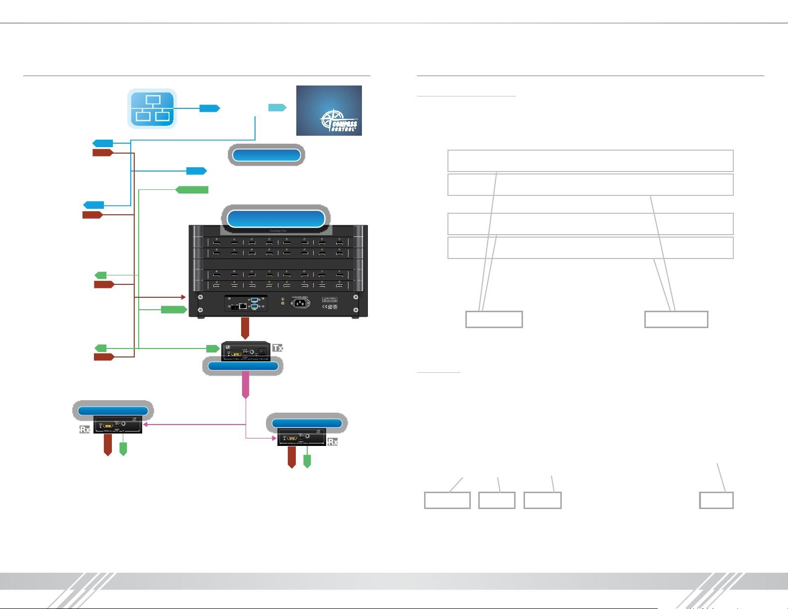
Application Example Connections, Buttons and LEDs
Satellite (x7)
x7
RJ45
HDMI
Ethernet
RJ45
WiFi Router
RJ45
WiFi
iPad
KD-MC1000
Rear Panel Connections:
All connections to the KD-16x16CS are found on the rear panel of the unit. Refer to the illustrations
below for port assignments while making connections:
x4
Digital Signage
Cable (x7)
Blu-Ray
RJ45
HDMI
x7
IR
HDMI
IR
HDMI
KD-CATHD250POH
HDMI
IR
x16
RS-232
x7
IR/RS-232
1-8
INPUTS
1-8
OUTPUTS
9-16
INPUTS
9-16
OUTPUTS
Master Controllers
KD-16x16CS
Cooling Fan
INPUTS
HDMI 1 HDMI 2 HDMI 3 HDMI 4 HDMI 5 HDMI 6 HDMI 7 HDMI 8
HDMI 1 HDMI 2 HDMI 3 HDMI 4 HDMI 5 HDMI 6 HDMI 7 HDMI 8
OUTPUTS
INPUTS
HDMI 9 HDMI 10 HDMI 11 HDMI 12 HDMI 13 HDMI 14 HDMI 15 HDMI 16
HDMI 9 HDMI 10 HDMI 11 HDMI 12 HDMI 13 HDMI 14 HDMI 15 HDMI 16
OUTPUTS
RS-232TCP/IPService
Keyboard
HDMI
x16
IR
KD-CATHD250POH
CAT5e/6
Up to 250’ with KD-CAT6STP1X
Up to 210’ with CAT5e/6
KD-CATHD250POH
HDMI
IR
INPUTS
OUTPUTS
INPUTS
OUTPUTS
x9
1-8
INPUTS
1-8
OUTPUTS
9-16
INPUTS
9-16
OUTPUTS
HDMI Inputs HDMI Outputs
› 16 HDMI Inputs are located in rows 1 & 3
› 16 HDMI Outputs are throughout rows 2 & 4
Main Ports
› Power, RS-232, Keyboard and Ethernet (TCP/IP) ports are located on the bottom-left of the
back panel. The RS-232 port utilizes a straight-through connection (see the RS-232 and TCP/IP
commands section of the manual for connection protocol and commands).
3x3 Video WallDisplays 1-7
Note: Model does not feature video wall processing/software
PowerRS-232TCP/IPKeyboard
› The Keyboard Service port is not currently active.
› Both RS-232 ports are available for use. There is no primary or secondary assignment.
› It is recommended that the unit is grounded via the Grounding Screw.
Page 4

4 5
Front Panel Connections:
Input Select Output Select Control Buttons
› There are 16 Input Select buttons on the left side of the front panel
› There are 16 Output Select buttons on the right side of the front panel
» A button will illuminate red when pressed
› Power LED & Sensor Window
› There are 6 control buttons located on the far right side of the front panel
› The top row of buttons in the Control section are not currently active
Power LED
Front Panel Operation
Switching
› Switching can be made for a single input / output selection, or for a single Input
to be assigned to multiple outputs
Memory and Recall Functions
The KD-16x16CS allows you to store up to 8 input/output configuration presets.
› Save:
» When you have your desired output-to-input relationships made, press
an input select number
› Recall:
» To recall a configuration, press
(1-8)
to save this configuration.
Recall ➔
then press the desired preset number
SAVE ➔
then press
you wish to recall
RS-232 and TCP/IP commands
The KD-16x16CS provides access to all functions when used with an RS-232 control system.
Connection protocol is as follows:
› Baud Rate = 9,600 bits per second
› Data Bits = 8
› Stop Bits = 1
› Parity = None
› Flow Control = None
› Carriage Return: Required
› Line Feed: Required
RS-232 cable pin out
Pin 5 – Ground
Pin 3 – Receive
Pin 2 – Transmit
Video RS
V/RS Enter
Recall
› There is also an optical IR window located on the right side of the front panel (to the right of the
Save
power indicator) for IR remote control signals. IR control currently is not active.
Important Notes:
› All commands shown below are case-sensitive
› “.”, “,” and “;” characters at the end of each command must be included
as indicated
› The ‘ and ’ characters around each command are not required,
they are shown for clarity
RS-232 Command Description
Switching Commands
xxByy.
xxAll.
Set Output yy to Video Input xx,
xx = 00 ~ 32(Max.), 00 = OFF, yy = 01 ~ 32 (Max.)
Ex: 01B01.
Set All Output to Video Input xx,
xx = 00 ~ 32(Max.), 00 = OFF
Ex: 01All.
Page 5

6 7
yy#.
All#.
yy$.
All$.
SaveN.
RecallN.
ClearN.
/%Lock;
/%Unlock;
/:BellOff;
/:BellOn;
/:MessageOff;
/:MessageOn;
RWEDID.
DefaultEDID.
<#SIPRxxx.xxx.xxx.xxx>
<#SUBRxxx.xxx.xxx.xxx>
<#GARxxx.xxx.xxx.xxx>
Set Output to pass-thru / respective Input.
Output 03 select Input 03
Set All Output to pass-thru / respective Input.
Output 01 select Input 01, Output 02 select Input 02 …
Output 24 select Input 24
Set Output OFF (no video and audio).
Output 04 set OFF.
Set All Output OFF
Store current matrix switch setting into the memory [N],
N = 1 ~ 8
Ex: Save1.
Recall the matrix switch setting from the memory [N] ,
N = 1 ~ 8
Ex: Recall1.
Note: Recalling a cleared/empty preset will turn off all outpus.
Clear the memory [N] by default setting, N = 1 ~ 8
Ex: Clear1.
Set Front Panel Buttons Disable
Set Front Panel Buttons Enable
Set the Bell Off
Set the Bell On
Set the Return Message Off at both RS232 and TCP/IP
Note: Status command will be unresponsive
Set the Return Message On at both RS232 and TCP/IP
EDID Setup
Copy EDID from Output 01 to All Inputs
Copy Default EDID (1080p@60, 2CH PCM) to All Inputs
Network Setup
Set IP Address xxx.xxx.xxx.xxx at TCP/IP Network Setting,
xxx = 000 ~ 255
Ex: <#SIPR192.168.000.239>
Set Net Mask xxx.xxx.xxx.xxx at TCP/IP Network Setting,
xxx = 000 ~ 255
Ex: <#SUBR255.255.255.000>
Set Router Address xxx.xxx.xxx.xxx at TCP/IP Network
Setting, xxx = 000 ~ 255
Ex: <#GAR192.168.000.001>
<#SPORTzzzz>
Set TCP Port zzzz at TCP/IP Network Setting,
zzzz = 0001 ~ 9999
Ex: <#SPORT0023>
Status/System Commands
/^Version;
Statusyy.
Status.
<^SIPR>
<^SUBR>
<^GAR>
<^SPORT>
<^SHAR>
Video Switching
‘xxByy.’
: To switch the desired video input (xx) to the desired output (yy)
» xx= the input number (00-16; 00=off)
» yy= the output number (00-16; 00=off)
» Example: To switch input 03 to output 01, issue the command: ‘03B01.’
‘xxAll.’
: To switch all outputs to a desired input
» Example: To switch all outputs to input 3, issue the command: ‘03All.’
» To turn OFF output 05, issue the command: ‘00B05.’
EDID Commands
‘DefaultEDID.’
‘RWEDID.
: Will copy the default 1080p, 2ch PCM EDID to all inputs
’: Will copy EDID from output 1 to all inputs
Status
‘Status.’
‘Statusyy.’
: Get all video output status
: Get status of output yy
» yy= the output number (01-16)
» Example: To get the status of output 2, issue the command: ‘Status02.’
RS-232 and TCP-IP Status Response:
A: 01
V: 01
A: 02
V: 02
➔
➔
➔
➔
001
001
002
002
A: 03
V: 03
A: 04
V: 04
➔
➔
➔
➔
003
003
004
004
A: 05
V: 05
A: 06
V: 06
Get the F/W version of matrix switcher
Get Video Output yy Status, yy = 01 ~ 32 (Max.)
Ex: Status01.
Get All Video Output Status
Get IP Address at TCP/IP Network Setting
Get Net Mask at TCP/IP Network Setting,
Get Route Address at TCP/IP Network Setting,
Get TCP Port at TCP/IP Network Setting,
Get MAC Address at TCP/IP Network Setting,
➔
➔
➔
➔
005
005
006
006
A: 07
V: 07
A: 08
V: 08
➔
➔
➔
➔
007
007
008
008
A: 09
V: 09
A: 10
V: 10
➔
➔
➔
➔
009
009
010
010
A: 11
V: 11
A: 12
V: 12
➔
➔
➔
➔
011
011
012
012
A: 13
V: 13
A: 14
V: 14
➔
➔
➔
➔
013
013
014
014
A: 15
V: 15
A: 16
V: 16
➔
➔
➔
➔
015
015
016
016
Page 6

8 9
TCP/IP Settings
The KD-16x16CS does not support DHCP. TCP/IP settings can only be changed via IP. Follow the
Network Setup commands below to configure your unit’s network settings.
Default TCP/IP Settings:
» IP Address: 192.168.0.239
» Network Mask: 255.255.255.0
» Router Address: 192.168.0.1
» TCP Port: 23
Specifications
Technical:
» Inputs: 16 HDMI Connectors, Type A, 19 Pin Female
» Outputs: 16 HDMI Connectors, Type A, 19 Pin Female
» Bandwidth: TMDS bandwidth 10.2 Gb/s
» Control: Pushbutton/LCD front, RS-232, TCP/IP
» HDMI Video/Audio Signal: Input Video Signal - 1.2 Volts p-p
» DDC Signal (Data): Input DDC Signal - 5 Volts p-p (TTL)
» DDC Communication: EDID and HDCP authentication by matrix to source and display
» Power: AC Power Supply (100V ~ 240V) 1A
General:
» Regulation: CE, RoHS, WEEE
» Rack Mount: 3U, Full Rack Width (rack ears included)
» Enclosure: Black Metal
» Product: 19” x 14” x 9”, Weight: 20 lbs.
» Shipping Weight: 45 lbs.
Important Product Warnings:
1. Connect all cables before providing power to the unit.
2. Test for proper operation before securing unit behind walls or in hard to access spaces.
3. If installing the unit into wall or mounting bracket into sheet-rock, provide proper screw support
with bolts or sheet-rock anchors.
Safety Instructions:
Please be sure to follow these instructions for safe operation of your unit.
1. Read and follow all instructions.
2. Heed all warnings.
3. Do not use this device near water.
4. Clean only with dry cloth.
5. Install in accordance with the manufacturer’s instructions.
6. Do not install near any heat sources such as radiators, heat registers, stoves, or other
apparatus (including amplifiers) that produce heat.
7. Only use attachments/accessories specified by the manufacturer.
8. Refer all servicing to qualified service personnel. Servicing is required when the device has
been damaged in any way including:
» Damage to the power supply or power plug
» Exposure to rain or moisture
Power Supply Use:
You MUST use the Power Supply provided with your unit or you VOID the
Key Digital
®
Warranty and risk damage to your unit and associated equipment.
Page 7

10 11
How to Contact Key Digital
®
Technical Support
For technical questions about using Key Digital® products, please contact us at:
› Phone: 914-667-9700
› E-mail: tech@keydigital.com
Repairs and Warranty Service
Should your product require warranty service or repair, please obtain a Key Digital® Return Material
Authorization (RMA) number by contacting us at:
› Phone: 914-667-9700
› E-mail: rma@keydigital.com
Feedback
Please email any comments/questions about the manual to:
› E-mail: customersupport@keydigital.com
Warranty Information
All Key Digital® products are built to high manufacturing standards and should
provide years of trouble-free operation. They are backed by a Key Digital
Limited Lifetime Product Warranty Policy.
» http://www.keydigital.com/warranty.htm
Page 8

12 13
 Loading...