

Key Digital Black Bull KD-HDRV2X1, Black Bull KD-HDRV3X1l, Black Bull KD-HDRV4X1 Operating Instructions Manual
Page 1
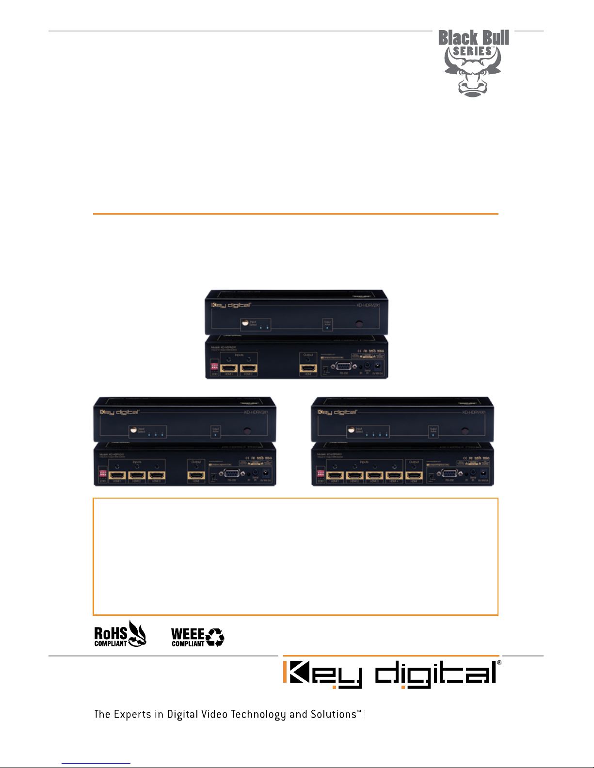
Operating Instructions
KD-HDRV2X1
KD-HDRV3X1 KD-HDRV4X1
Key Digital Black Bull Series™ HDMI/DVI switchers are designed and engineered to offer the
best in quality, performance, and reliability while providing a cost effective HDMI/DVI switching
solution. The KD-HDRV2X1, KD-HDRV3X1, KD-HDRV4X1 HDMI switchers provide multiple
input to one output switching and maintain crystal-clear, pristine picture and sound quality.
Key Digital Black Bull Series™ switchers are a transparent solution for all digital video/audio
switching applications and support all HD and SD video standards, including 1080p/60. KDHDRV switchers feature iAS™ Intelligent Auto Sense signal detection and switching, pushbutton
control, IR, RS-232, status-monitoring LEDs, and support for HDMI CEC.
Black Bull Series
HDMI Switchers
Page 2
Page 2
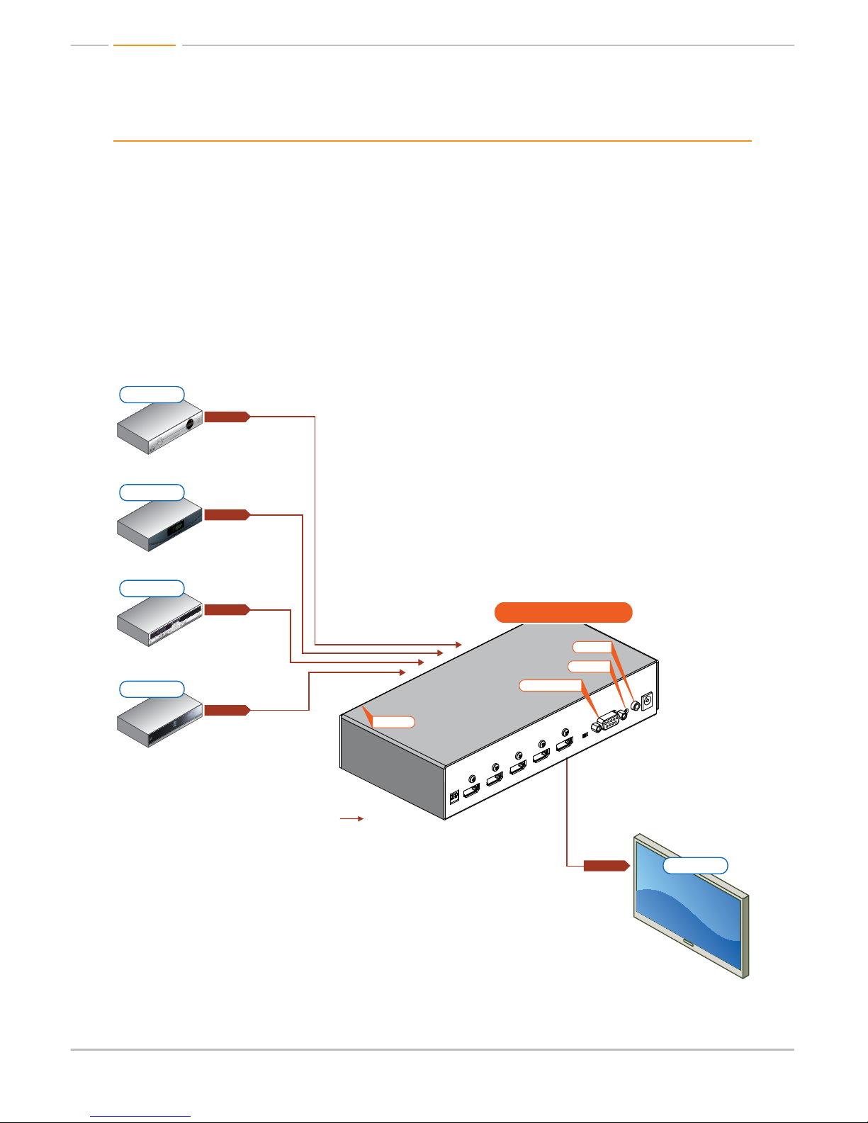
Quick Setup Guide
½ Step 1: Find a safe and convenient location to mount or place your KD-HDRV unit
½ Step 2: Begin with the KD-HDRV unit and all input/output devices turned off with power cables
removed
½ Step 3: Connect your HDMI or DVI-D source devices to the input ports of your KD-HDRV unit
½ Step 4: Connect your HDMI or DVI-D display to the output port of your KD-HDRV unit
½ Step 5: Connect the desired IR or RS-232 control inputs to your KD-HDRV unit
½ Step 6: Be sure the Operation Mode Switch is set to the “Normal” position
½ Step 7: Connect power to the KD-HDRV unit
½ Step 8: Power on input/output devices
Note: No signal conversion is done on the KD-HDRV2X1; KD-HDRV3X1; KD-HDRV4X1.
If input signal is HDMI output signal will be HDMI. If input signal is DVI output signal will be DVI.
HDMI/DVI
HDMI/DVI
HDMI/DVI
*
HDMI/DVI
*
HDMI/DVI
*
HDMI/DVI
*
HDMI/DVI
*
HDMI/DVI
*
HDMI/DVI
*
HDMI/DVI
*
HDMI/DVI
*
HDMI/DVI
*
Plasma TV
Blu-Ray
DVD Player
Cable Box
Satellite Box
KD-HDRV4X1
KD-HDRV4X1
RS-232 Control
Serial IR
Optical IR
*To connect DVI use Key Digital® HDMI to DVI adapters, part numbers KD-FMHDMI and KD-MFHDMI
Serial IR
Optical IR
RS-232 Control
Optical IR
Optical IR
*To connect DVI use Key Digital® HDMI to DVI adapters, part numbers KD-FMHDMI and KD-MFHDMI
Page 3

Page 1
Table of Contents
Introduction . . . . . . . . . . . . . . . . . . . . . . . . . . . . . . . . . . . . . . . . . . . . . . . . . . . . . . . . . . . . . . . . 2
About KD-HDRV2X1; KD-HDRV3X1; KD-HDRV4X1 . . . . . . . . . . . . . . . . . . . . . . . . . . . . . 2
DVI Applications for KD-HDRV2X1; KD-HDRV3X1; KD-HDRV4X1 . . . . . . . . . . . . . . . . . . . . . . . 2
Accessories. . . . . . . . . . . . . . . . . . . . . . . . . . . . . . . . . . . . . . . . . . . . . . . . . . . . . . . . . . . . . . . . 3
Installation and Operation. . . . . . . . . . . . . . . . . . . . . . . . . . . . . . . . . . . . . . . . . . . . . . . . . . . . . . 3
Push Button Control . . . . . . . . . . . . . . . . . . . . . . . . . . . . . . . . . . . . . . . . . . . . . . . . . . . . . 3
Remote Control . . . . . . . . . . . . . . . . . . . . . . . . . . . . . . . . . . . . . . . . . . . . . . . . . . . . . . . . 3
IR Emitter Control . . . . . . . . . . . . . . . . . . . . . . . . . . . . . . . . . . . . . . . . . . . . . . . . . . . . . . . 4
RS-232 Control and Commands. . . . . . . . . . . . . . . . . . . . . . . . . . . . . . . . . . . . . . . . . . . . 4
Multiple KD-HDRV Unit Configurations . . . . . . . . . . . . . . . . . . . . . . . . . . . . . . . . . . . . . . . . . . . . 5
Addressing Buttons / Units via IR . . . . . . . . . . . . . . . . . . . . . . . . . . . . . . . . . . . . . . . . . . . 5
Addressing Buttons / Units via RS-232 . . . . . . . . . . . . . . . . . . . . . . . . . . . . . . . . . . . . . . . 5
EDID Control Settings . . . . . . . . . . . . . . . . . . . . . . . . . . . . . . . . . . . . . . . . . . . . . . . . . . . . . . . . 6
Using iAS
™
Intelligent Auto Sense . . . . . . . . . . . . . . . . . . . . . . . . . . . . . . . . . . . . . . . . . . . . . . . 6
Firmware Upgrades . . . . . . . . . . . . . . . . . . . . . . . . . . . . . . . . . . . . . . . . . . . . . . . . . . . . . . . . . . 7
Mechanical / Technical Specifications . . . . . . . . . . . . . . . . . . . . . . . . . . . . . . . . . . . . . . . . . . . . 8
Important Product Warnings . . . . . . . . . . . . . . . . . . . . . . . . . . . . . . . . . . . . . . . . . . . . . . . . . . . 8
Safety Instructions . . . . . . . . . . . . . . . . . . . . . . . . . . . . . . . . . . . . . . . . . . . . . . . . . . . . . . . . . . . 9
How to Contact Key Digital
®
. . . . . . . . . . . . . . . . . . . . . . . . . . . . . . . . . . . . . . . . . . . . . . . . . . . . 9
Warranty Information . . . . . . . . . . . . . . . . . . . . . . . . . . . . . . . . . . . . . . . . . . . . . . . . . . . . . . . . . 9
© 2010 Key Digital, Inc. All rights reserved.
Always follow the instructions provided in this Operating Manual.
Page 4
Page 2
Introduction
Thank you for purchasing a Key Digital Black Bull Series™ KD-HDRV HDMI switcher. KD-HDRV
switchers are designed to interface your HDMI or DVI-D source devices, such as DVD players,
Satellite Boxes, Digital Video Recorders (DVR), Set Top Box, or PCs to your HDMI or DVI-D
compatible display.
About the KD-HDRV2X1; KD-HDRV3X1; KD-HDRV4X1
½ Digital switching of multiple (2, 3, or 4) HDMI inputs to one (1) HDMI output
½ Supports all SD, HD, and VESA (VGA, SVGA, XGA, WXGA, SXGA, UXGA) resolutions up to
1080p (60Hz & 50Hz)
» SD & HD: 480i, 480p, 720p, 1080i, 1080p
» VESA / DVI: From 640x480p up to 1920x1200p
½ EDID Control featuring 4 internal library settings or auto EDID selection of display
½ Supports signal rates up to 10.2 Gb per second
½ iAS
™
Intelligent Auto Sensing of signal presence and switching to active input
½ Supports HDMI and DVI-D
½ Compliant with HDCP copyright protection
½ Compliant with HDMI 1.3
½ Supports CEC (Consumer Electronics Control)
½ Pushbutton, IR Sensor, and RS-232 control
½ Input and Output status indicated by LED
½ Compatible with all control systems
½ Firmware upgradable
½ Rack mountable
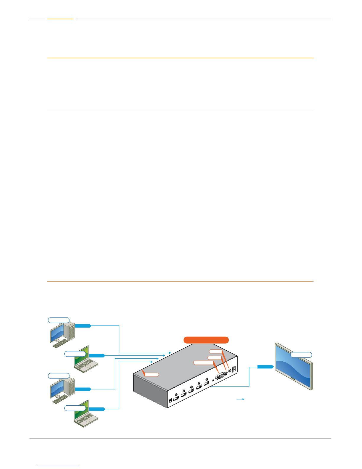
DVI Applications for KD-HDRV2X1; KD-HDRV3X1; KD-HDRV4X1
KD-HDRV switchers can also be used with DVI-D sources and displays. For these applications,
use DVI to HDMI (Key Digital model number KD-MFHDMI or KD-FMHDMI) adapters. Note that
while HDMI supports both video and audio over an HDMI cable, DVI-D supports only video.
DVI
*To connect DVI use Key Digital® HDMI to DVI adapters,
part numbers KD-FMHDMI and KD-MFHDMI
DVI Video*
DVI Video*
DVI Video*
DVI Video*
DVI Video*
HDMI/DVI
HDMI/DVI
HDMI/DVI
*
HDMI/DVI
*
HDMI/DVI
*
HDMI/DVI
*
HDMI/DVI
*
Plasma TV
Plasma TV
HDMI/DVI
*
HDMI/DVI
*
HDMI/DVI
*
HDMI/DVI
*
HDMI/DVI
*
Plasma TV
Blu-Ray
DVD Player
Cable Box
Satellite Box
Desktop PC
Laptop
Laptop
Desktop PC
KD-HDRV4X1
KD-HDRV4X1
KD-HDRV4X1
RS-232 Control
Serial IR
Optical IR
*To connect DVI use Key Digital® HDMI to DVI adapters, part numbers KD-FMHDMI and KD-MFHDMI
Serial IR
Optical IR
RS-232 Control
Optical IR
RS-232 Control
Serial IR
Optical IR
Optical IR
Optical IR
*To connect DVI use Key Digital® HDMI to DVI adapters, part numbers KD-FMHDMI and KD-MFHDMI
Page 5

Page 3
Accessories
½ External 5 Volt 1 Amp power supply
½ IR Remote Control
½ Rack Ears
½ Operating Instructions
½ Warranty Card
½ IR Receiver with 3.5 mm Male Stereo Plug
Installation and Operation
Before permanently securing the unit for final installation of cabling behind walls or ceilings, test
for proper operation of the unit and the cables in your system. It is recommended that you leave
enough ventilation space to provide sufficient airflow and cooling, especially if you are going to
leave the unit powered at all times.
Pushbutton Control
Your KD-HDRV unit may be controlled via the pushbutton on the front of the unit. Select your
desired input by depressing the “Input Select” button. The front LED indicators (1, 2, 3, 4)
correspond to the input that has been selected.
IR Remote Control
The KD-HDRV can also be operated using the IR remote control provided with your unit. The
KD-HDRV switcher features IR sensors on the front and rear of the unit for reception of the IR
command signals.
1 2 3 4
1 2 3
R1
4 5
7 8
6
R2
0
9
R3
Device Select
Auto
Power OffPower On
www.keydigital.com
Input
Power On
Power Off
Auto Input Select
Input Select
Scroll Down
Input Select
Input Select
Scroll Up
R1, R2, R3
Reserved for future use
Numeric Keypad
Used in addressable
mode for specifying
unit’s address
Page 6

Page 4
Serial IR & IR Emitter Control
½ The “Serial IR” port requires the use of a Male 3.5mm Mono cable (not included) with the IR
command signal being carried on the “Tip” of the input inserted into the KD-HDRV unit. The
location of the IR signal may vary by control system used. Please verify the location of the IR
signal with your control system.
½ When using the IR Emitter / IR Extender (sold separately), the
IR Emitter must be mounted over the IR Sensor on the KDHDRV unit. It is recommended that the rear IR sensor of the
KD-HDSW unit be utilized for these applications. One end of
the cable is connected to the IR Receiver / Master Controller
/ IR Extender / IR Connecting Block, while the other end is
mounted over the IR Sensor of the KD-HDRV unit.
RS-232 Commands and Protocol
½ KD-HDRV units are compatible with all Control Systems, such as AMX
®
, Control4®, Crestron®,
RTI
®
, Universal
®
½ Connect your Control System’s Master Controller to the KD-HDRV unit using the RS-232 port.
Follow all instructions provided with your control system.
½ RS-232 Protocol:
» Baud Rate = 9600 bits per second
» Data Bits = 8
» Parity = None
» Stop Bits = 1
» Flow Control = None
RS-232 Command List:
RS-232 Command Description Comments
pwr_1 Power On
pwr_0 Power Off
sel_x x = 1-4, 5, 6 1-4 = Input #, 5 = Up, 6 = Down
asl Auto Select Enable/
Disable
hep Help Full RS-232 command listing
sta Status “s1y” y = active input
Ground
Signal
Page 7

Page 5
sir_x_x_y Addressing per
Command
x x = desired two-digit address for
command (01 – 99)
y = Input Select, Up, Down (1-4, 5, 6)
gir Address Setting Status
dir_y Delete Address Setting
per Command
y = Input Select, Up, Down (1-4, 5, 6)
½ All RS-232 commands must be in lower case letters, require spaces where indicated above with
( _ ), and require a carriage return to be sent.
Multiple KD-HDRV Unit Configurations
Up to 99 individually addressable units can be installed. KD-HDRV switchers allow you to assign a
two-digit address to each unit or each of the selectable inputs. This capability can be configured
via IR or the RS-232 port.
½ Addressing Buttons / Units via IR
» With power enabled on the unit, press the “Power On” button. The “Input Select” LED
lights will begin to blink, indicating that the KD-HDRV unit is ready to receive the address
information.
» Press the first digit (0 – 9) of the two-digit address. Once this first digit has been received
“Input Select 1” LED will blink.
» Press the second digit (0 – 9) of the two-digit address. Once this second digit has been
received “Input Select 1” and “Input Select 2” LED’s will blink.
» Press the Input Select button (Input 1 – Input 4, Up or Down) that you wish to assign the
two-digit address to. Once this is completed, all “Input Select” lights will become solid
indicating that the Input Select button has now been re-addressed.
» Repeat Steps 2 through 4 if you wish to assign an address to additional “Input Select”
buttons or to your entire KD-HDRV unit.
» Press “Power On” button to exit addressing mode when completed.
½ Addressing Buttons / Units via RS-232
» See “RS-232 Commands and Protocol” section for RS-232 Addressing Commands
» To address an Input, use “sir_x_x_y” command. To address an entire unit, repeat command
for each Input, Up, and Down
» For address settings, use “gir” RS-232 command to receive a list of address settings
» To delete address settings, issue “dir_y” RS-232 command
Page 8

Page 6
EDID Control Settings
At times, your HDMI sources and display may not synchronize properly.
This is when EDID* control should be utilized. KD-HDRV switchers
feature an internal library of default settings that modify KD-HDRV input
port’s EDID to ensure that your HDMI source’s output is compatible with
your display.
Dip Switch Configurations:
Configuration Description
000
Bypass (EDID Information of Display)
001
Video = 1080i, Audio = L/R Stereo
010
Video = 1080i, Audio = All Audio formats including HDMI 1.3a/b
011
Video = 1080p Audio =L/R Stereo
100
Video = 1080p Audio = All Audio formats including HDMI 1.3a/b
All Others
Bypass (EDID Information of Display)
* EDID (Extended display identification data) is a data structure provided by a display to describe its
capabilities to a source device.
Using iAS Intelligent Auto Sense
™
iAS Intelligent Auto Sense™ will switch automatically when Hot
Plug Detect signal becomes active on an input. iAS Intelligent
Auto Sense
™
can be enabled and disable via IR or RS-232 control.
Please note that many common HDMI sources, such as a Cable or Satellite Box, will emit Hot Plug
Detect signals when in stand-by mode and may prevent full functionality of iAS Intelligent Auto
Sense
™
.
Page 9

Page 7
Firmware Upgrades
From time-to-time, Key Digital provides updates for the firmware that operates and controls your
KD-HDRV unit. These updates are optional, and you should only perform upgrades as provided
and instructed by Key Digital. Periodically check out web site at www.keydigital.com for the latest
firmware updates for your unit.
Firmware Upgrade Procedure
1. Make sure you have the required equipment for upgrading your KD-HDRV device:
» a. PC with a serial port capable of 57600 Baud Rate
» b. Straight male-female DB9 serial cable no longer that 10 ft.
Note: Null modem cable is NOT supported.
2. Download desired firmware from www.keydigital.com. Unzip the firmware ZIP file to any
directory on your PC.
3. Make sure that no devices are using the Serial COM port on your PC.
4. Disconnect Power from the KD-HDRV unit.
5. Set the rear panel Operation switch to “Program”.
6. Connect an RS-232 cable to the serial port on your PC and the other end to the RS-232 port
on the rear panel of the KD-HDRV unit.
7. Double-click the “UartBootLoader.exe” file. The Key Digital BootLoader window will pop up.
8. Reconnect Power to the KD-HDRV unit.
9. Select the correct port used for your computer’s RS-232 connection.
10. Push “Open File” button and select firmware file (file extension .hex)
11. Press “Start” button
12. When the firmware had been updated, disconnect the power supply from your KD-HDRV unit.
The power supply MUST be disconnected (either from the back of your unit or from the wall
outlet) to have a complete power shutdown reset.
13. Disconnect the RS-232 cable between the unit and your PC.
14. With the power disconnected, set the rear-panel Operation switch to “Normal” mode.
15. Reconnect the power supply to your KD-HDRV unit. The firmware upgrade is now complete
and your KD-HDRV unit is now ready for operation.
Page 10

Page 8
Mechanical / Technical Specifications
Inputs
4/3/2 HDMI Connectors
Outputs
1 HDMI Connector
Bandwidth
TMDS bandwidth 10.2 Gb/s
Compliance With
HDMI Standard
Supports HDMI1.3+, HDMI1.2, HDMI1.1, DVI1.1 and HDCP.
Link
Single Link: 1080p/60, 12 bit color depth, 1920x1200 max.
Deep Color Support
Supports digital video formats in Deep Color Mode
at up to 12 bits/color
Lossless Compressed
Digital Audio
Supports lossless compressed digital audio
(Dolby
®
TrueHD, Dolby® Digital Plus and DTS™-HD Master Audio)
DDC Signal (Data)
Input DDC Signal: 5 Volts p-p (TTL)
HDMI Video/Audio Signal
Input Video Signal: 1.2 Volts p-p
HDMI Connector
HDMI Connector: Type A, 19 Pin Female
I2C Communication
EDID and HDCP Bi-Directional Transparency from Display to
Source
EDID Control
Active outputs connected via HDMI, or from internal library of
default 4 EDID settings
Control
For RS-232 Db9 Female connector for Tx, Rx and ground.
For IR two optical windows and wired 3.5 mm female mini-stereo
connector. Push button and top LED’s.
Switching
Switching of all Video and Audio simultaneous
Power Source
5 Volt DC @ 1 Amp, 100-240 VAC, 50-60 Hz
Dimensions
W=8.5”, H=1.75”, D=4”
Weight
2 Lbs
Important Product Warnings:
1. Connect all cables before providing power to the unit.
2. Test for proper operation before securing unit behind walls or in hard to access spaces.
3. If installing the unit into wall or mounting bracket into sheet-rock, provide proper screw support
with bolts or sheet-rock anchors.
Safety Instructions.
Please be sure to follow these instructions for safe operation of your unit.
1. Read and follow all instructions.
2. Heed all warnings.
Page 11

Page 9
3. Do not use this device near water.
4. Clean only with dry cloth.
5. Install in accordance with the manufacturer’s instructions.
6. Do not install near any heat sources such as radiators, heat registers, stoves, or other
apparatus (including amplifiers) that produce heat.
7. Only use attachments/accessories specified by the manufacturer.
8. Refer all servicing to qualified service personnel. Servicing is required when the device has
been damaged in any way including:
» Damage to the power supply or power plug
» Exposure to rain or moisture
You MUST use the Power Supply provided with your unit or you VOID
the Key Digital
®
Warranty and risk damage to your unit and associated equipment.
How to Contact Key Digital
®
System Design Group (SDG)
For system design questions please contact us at:
½ Phone: 914-667-9700
½ E-mail: sdg@keydigital.com
Technical Support
For technical questions about using Key Digital® products, please contact us at:
½ Phone: 914-667-9700
½ E-mail: tech@keydigital.com
Repairs and Warranty Service
Should your product require warranty service or repair, please obtain a Key Digital® Return Material
Authorization (RMA) number by contacting us at:
½ Phone: 914-667-9700
½ E-mail: rma@keydigital.com
Feedback
Please email any comments/questions about the manual to:
½ E-mail: customersupport@keydigital.com
Warranty Information
All Key Digital® products are built to high manufacturing standards and should provide years of
trouble-free operation. They are backed by a limited two-year parts and labor warranty.
Page 12

521 East 3rd Street, Mount Vernon, NY 10553
Phone :: 914.667.9700 Fax :: 914.668.8666
Web :: www.keydigital.com
Key Digital®, led by digital video pioneer Mike Tsinberg,
develops and manufactures high quality, cutting-edge
technology solutions for virtually all applications where
high quality video imaging is important. Key Digital
®
is at the forefront of the video industry for Home
Theater Retailers, Custom Installers, System Integrators,
Broadcasters, Manufacturers, and Consumers. We
provide
total video system solutions because we
know and help drive the technology, the industry, the
business, and all the latest up-and-coming standards.
But most of all, we know exactly what you need for your
unique application - the right solution.
Rev 0 – April 2010
 Loading...