

Page 1
OPERATION MANUAL
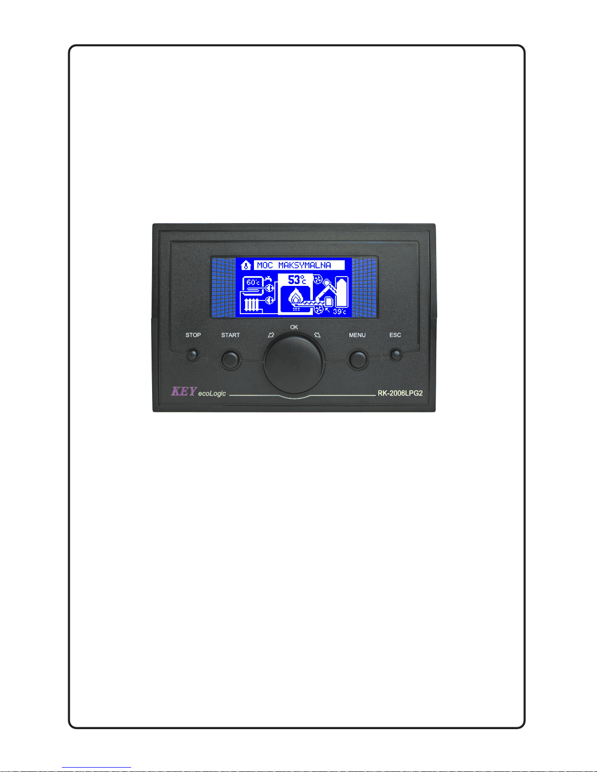
RK-2006LPG2
Pellet fuel burner fitted boiler temperature controller.
Wersja 4B00
Page 2

Page 3

3
1. Application.
Controller RK-2006LPG2 is designed for temperature control of solid fuel fired water
boilers equipped with:
- Auger and feeding stoker working with the stoker,
- Blow-in fan,
- Ignition glow plug for automatic start,
- Central heating pump,
- Hot tap water pump or mixing pump (option),
- Alarm indicator or or ash removal system (option),
- Room thermostat (option).
2. Connection.
Before turning on the controller, connect: power cables of: controller, blow-in fan,
central heating and hot tap water pumps and auger to appropriate sockets in the
rear of the controller. The temperature sensor should be placed in metering locations
that shall be dry. Figure 2 presents the electrical connection diagram. For connection
of stoker, alarm indicator and ash removal system the additional module UM-1 shall
be applied.
CAUTION! Before plugging in the controller first check if the wiring system is
properly grounded, and if the terminal screws of the output connector are tightened.
CAUTION!Total power of the fan, central heating and hot water pump which are
connected to the controller must not exceed 900W. Outputs of the controller that are
not used may remain disconnected.
CAUTION! Control outputs of the feeder and lighter are not protected and MUST BE
protected with adequate fuses.
CAUTION! The controller is equipped with properly protected semiconductor
temperature sensors, yet metering locations with installed sensors must be dry.
Page 4
4
3. Operation.
After power-up the controller displays the name and version of the software, then
goes to the state it was in before shutting down or lose power.
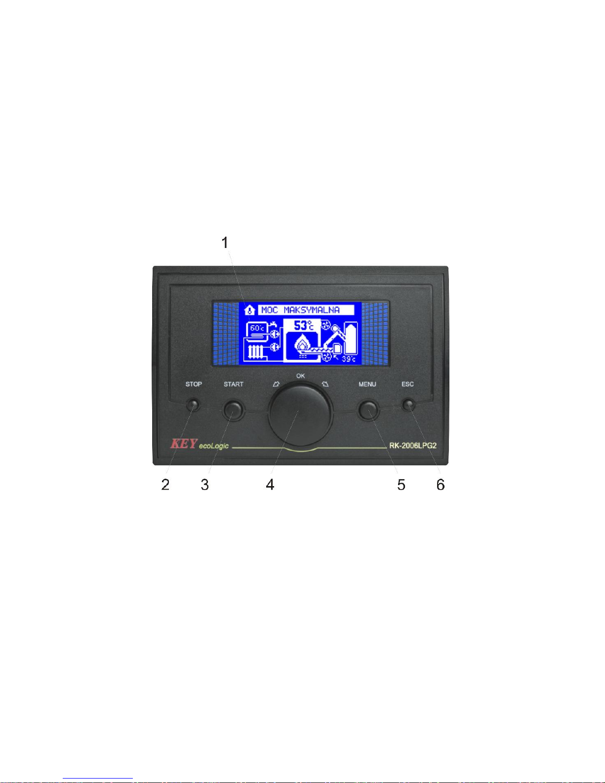
On the front panel of the controller (Figure ) there is:
1 – display,
2 – STOP button, reset the alarm and cancel the changes,
3 – START button and choose the parameter,
4 – the boiler thermostat knob and set the parameters and click OK,
5 – MENU button and choose the parameter,
6 – ESC / output.
Figure 1. Front panel of RK-2006LPG2 controller.
Basic operation of the device is to set the preset boiler temperature. In this hands?
U need to turn the boiler thermostat knob (4) to set the correct value and confirm it
with the OK button (or press the knob).
CAUTION! If you enter the room thermostat works in adaptive mode, you try to
change the set temperature of the boiler may end in failure, ie. After approval of the
new value of the controller can automatically change the boiler temperature to
a value that results from the operation of the adaptive algorithm.
CAUTION! If the heating system has a water heater, the water temperature in the
boiler maintained by the controller during the heating tray may be higher than the set
temperature of the thermostat knob.
Page 5
5
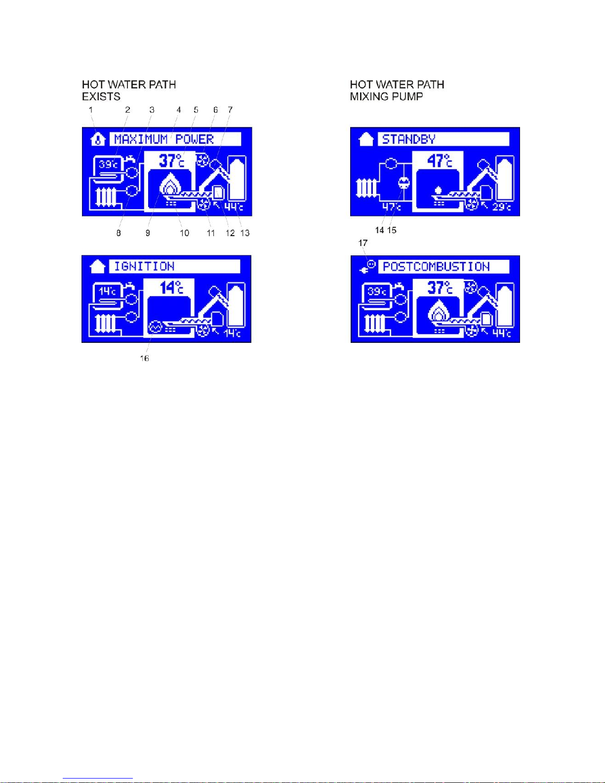
Overview of display symbols.
1 – Thermostat work indicator,
2 – DHW temperature,
3 – DHW pump work indicator,
4 – Controller work mode,
5 – Boiler water temperature,
6 – Additional fan,
7 – Feeder work indicator,
8 – CH pump work indicator,
9 – Burner capacity indicator (the higher the capacity, the brighter the flame),
10– Cleaning device work indicator,
11– Fan,
12– Stoker work indicator,
13– Feeder temperature,
14– Return water temperature,
15– Mixing pump work indicator,
16– Ignitor work indicator.
17– Emergency power system work indicator.
Page 6

6
4. Device operation modes.
Table 1. Operation mode list.
Operation mode.
Description
STOP Boiler control stopped. Controller maintains central heating and domestic water
pump operation, but automatic ignition does not follow.
STAND-BY Controller maintains central heating and domestic water pump operation. In case
of heat demand automatic ignition of boiler follows.
IGNITION Controller carries out automatic ignition of boiler.
STABILIZATION
OF THE FIRING
Fan control and feeder so as to stabilize the
the burner.
MAX. POWER Fan and fuel feeder operates to reach boiler max. power.
MODUL.
POWER
Controller reduces fuel feeding as much as boiler water temperature
corresponds to the desired setting.
MINIMUM
POWER
Fan and fuel feeder operation is minimize to maintain fire.
SCAVENGE
(AIR PURGING)
Controller activates blower to ensure removal of accumulated gases.
AFTERBURNING No demand for heat or furnace needs cleaning. The controller turns off the tray
and burnout of fuel until the flame failure.
EXTINCTION The controller suppresses the boiler furnace.
CLEANING Burner cleaning.
AUGER
(MANUAL)
REFILLING
Manual operation of fuel auger. Boiler control stopped. Controller maintains
central heating and domestic water pumps operation, but automatic ignition does
not follow.
AUGER
EXTINCT
(EMERGENCY
SHUT DOWN)
Fuel ignition in auger channel. The controller empties ignited fuel from the auger
channel until temperature drops.
ALARMS Safety and temperatures sensors failure alarms.
STOP.
Controller maintains central heating and domestic water pumps operation only to
protect the boiler against overheating and auger channel ignition. Room thermostat
contacts closing(call for heat) and domestic water temperature drop do not result in
any action. Pressing START button will result in switching the controller to
STAND-BY mode.
STAND-BY.
In this mode controller does not carry out any additional operation, until room
thermostat contacts close (call for heat) or domestic water temperature drop, the
boiler operation will focus on maintenance of temperature according to thermostat
setting programmed with the knob. If preheating of domestic water tank is necessary
and the desired boiler temperature setting is higher from domestic water
temperature setting the controller will follow higher setting. Pressing the STOP
button () will result in switching to STOP mode.
IGNITION.
Boiler controller is switched into IGNITION mode if demand for heat follows, and if
the controller did not detect the flame. During ignition the controller activates fan,
auger and igniter. Fuel and air feeding rate is adjusted by the technician. IGNITION
Page 7

7
mode follows till flame is detected. If the flame is not detected within the specified
time, the controller activates „Out of fuel alarm”. Pressing STOP button, exceeding
time limit for cleaning, thermostat contacts opening or if water temperature in
domestic water tank is obtained during operation in IGNITION mode will result in
switching of the controller into EXTINCTION (SHUT DOWN) mode.
Stabilization of the firing.
Boiler burner is switched to the stabilization of the detected flame ignition. While
stabilizing the fan runs at a speed the same as when operating in maximum power.
Tray gives fuel quantity such as the minimum power. In addition, depending on the
service settings fuel dose may be increased gradually. Stabilization of the firing
continues for the time programmed in the settings of the service or until the boiler
temperature. Pressing the STOP button, exceeding the working time without
cleaning, opening the contacts of the thermostat or to achieve the required water
temperature in the hot water tank during operation stabilization ignition, the controller
will switch to after-burning mode.
CAUTION! Stabilization of ignition can be turned off by a service technician. In this
case, after the fire the controller switches to work with maximum power.
MAX. POWER OPERATION MODE.
When in this mode the controller operates fuel auger and fan to ensure max. power
of the boiler. Fuel and air feeding rate is adjusted by the technician. Pressing STOP
button, exceeding time limit for cleaning, thermostat contacts opening or if water
temperature in domestic water tank is obtained during operation in MAX. POWER
mode will result in switching of the controller into EXTINCTION (SHUT DOWN)
mode.
MODULATED POWER OPERATION MODE.
Depending on desired parameters the controller may gradually reduce fuel and air
rate feeding to reduce burner power, as much as boiler water temperature
corresponds to the programmed setting. Pressing STOP button, exceeding time limit
for cleaning, thermostat contacts opening or if water temperature in domestic water
tank is obtained during operation in MODULATED POWER mode will result in
switching of the controller into EXTINCTION (SHUT DOWN) mode.
MINIMUM POWER OPERATION MODE.
When in this mode the controller operates fuel feeding and fan operation to maintain
firing to ensure the minimum fuel consumption. Fuel and air feeding rate is adjusted
by the technician. If in spite of boiler minimum power, increase temperature follows
of water temperature in relation to the top hysteresis parameter setting, the controller
will be switched into EXTINCTION(SHUT DOWN) mode. When the boiler water
temperature drops below the desired setting it will result in switching of the controller
into „max power operation mode”. Pressing STOP button, exceeding time limit for
cleaning, thermostat contacts opening or if water temperature in domestic water tank
is obtained during operation in MINIMUM POWER mode will result in switching of
the controller into EXTINCTION (SHUT DOWN) mode.
Page 8

8
SCAVENGE (AIR PURGING).
During the operation with minimum power output, the controller will activate flue
scavenge (purging) to ensure removal of accumulated gases. Scavenge (purging) is
provided with temporary fan operation in higher speed.
EXTINCTION (SHUT DOWN).
When in this mode the controller turns off the fuel auger and engages the fan to
ensure complete fuel combustion and the burner cool down. Fan power when in
EXTINCTION (SHUT DOWN) mode is determined by the technician. When
EXTINCTION (SHUT DOWN) is finished the controller is switched into CLEANING,
STAND-BY or STOP mode, provided EXTINCTION (SHUT DOWN) followed as
a result of STOP button pressing.
Blanking mode.
In this mode, the controller changes the fan speed on the value programmed by a
service technician to burn off excess fuel and cool the burner. After putting out the
fire controller switches to CLEANING, ARMED or STOP depending on what caused
the start of the sequence Afterburning EXTINCTION.
CLEANING.
Automatic burner cleaning occurs after time set limit by programmer. In this mode
controller starts cleaning system for preset time. After this procedure controller
resets back to STANDBY mode.
AUGER (MANUAL) REFILLING.
User may activate auger manual refilling function. When device is in STOP mode,
press START and hold button for 5 seconds to start refilling. Refilling follows
according to the time programmed by the technician or until it is manually turned off
with STOP button.
AUGER EXTINCTION (EMERGENCY SHUT DOWN).
If the auger is equipped with a temperature sensor, a temperature increase above
the range programmed by the technician, it will result in activation of auger ignition
alarm. The controller turns off the fan and auger. If the burner is equipped with the
stoker, the device is switched additionally into AUGER EXTINCTION(EMERGENCY
SHUT DOWN) mode. During shut down the stoker is engaged for the time needed to
remove the ignited fuel from the stoker. In addition if the burner has cleaning
mechanism, the controller will activate the cleaning cycle and remove fuel from the
burner.
Page 9

9
ALARMS.
RK-2006LPG2 controller continually checks operations of installed devices as well
as alarm sensors. In case of failure, the device activates alarm and proper
operations are carried out. Information on the problem is also shown on the display.
In addition depending on nature of damage the inner sound alarm system may be
activated. To cancel alarm, first identify the cause and repair it and then STOP
button shall be pressed. If alarm is cancelled and required repairs did not follow,
sound alarm system will be turned off only. In case more than one alarm has been
activated, information on each alarm will be displayed alternately.
Out of fuel alarm.
If in IGNITION mode the controller fails to detect a flame within the time specified by
the technician, „Out of fuel alarm” will be activated. To turn on the controller again
first refill fuel, cancel the alarm with STOP button and begin setting-up process by
pressing START button.
Emergency alarm.
Depending on construction type, the boiler may be equipped with emergency sensor
(e.g. hopper cover sensor). Activation of the alarm will result in fan and auger turning
off, and switching the controller into STAND-BY mode.
CAUTION! This alarm does not result in engagement of inner sound system and
does not require cancelling. Once the hopper cover is closed, the programmed
process will be carried out from the moment when it was interrupted (it returns to the
mode that was before alarm activation).
Auger ignition alarm.
If the auger has been equipped with a temperature sensor, and the programmed
setting of „Auger ignition temperature" was exceeded, it will result in activation of
auger ignition alarm. The controller will go to SHUT DOWN mode.
Page 10

10
CAUTION! This alarm may be cancelled only if the auger temperature drops below
set point. If the alarm was cancelled before extinction completion, only sound alarm
will be turned off.
Auger sensor damage.
In case of auger temperature sensor damage, as in case of overheating, the
controller will go to shut down mode and will activate the appropriate alarm:
CAUTION! This alarm may be cancelled only after repairs.
Burner temperature sensor damage.
If flame temperature detector (CT-1/2 or PT-1000) has been connected to the
controller, its damage will result in activation of the alarm and switching into
STAND-BY mode.
Protection against overheating and overheating of the boiler.
RK-2006LPG is protected against overheating of the boiler. If the water temperature
reaches a preset value in parameter TEMP service. MAXIMUM THE BOILER, the
controller activates the pump absolutely CO. The increase in water temperature in
the boiler to the value programmed in parameter service TEMPERATURE BOILER
OVERHEAT will turn off the fan, heating pump, switch the controller to STOP mode
without starting the process of extinction and trigger the alarm:
CAUTION! This alarm may be cancelled, if boiler water temperature drops below the
overheating temperature setting.
Page 11

11
Boiler temperature sensor damage.
In case of boiler water temperature sensor damage the controller turns off the fan,
engages central heating pump, controller switches into STOP mode and activates
alarm:
CAUTION! This alarm may be cancelled, only if repairs are made.
Domestic water temperature sensor damage.
If the heating system is fitted with domestic water circuit, in case of sensor damage
the controller turns off the domestic water pump and activates alarm:
CAUTION! This alarm does not require cancellation. The alarm is deactivated
automatically, if repairs are made.
Return water temperature sensor damage.
If the heating system is provided with the mixing pump, in case of return water
temperature sensor damage, the pump is switched off and the controller activates
alarm:
CAUTION! This alarm does not require cancellation. The alarm is deactivated
automatically, if repairs are made.
5. Preview and set user parameters.
Pressing the MENU button we can view the following user parameters.
Page 12
12
The user can switch between different parameters by turning the knob (4).
By pressing the knob you enter the mode of change of the selected
parameter – the parameter will be backlit. You can change the value of the
selected parameter by turning the knob. To confirm the change press the
knob again, and the controller will return to the list of parameters. To leave
the mode of change and restore the previous value of a parameter, press
the MENU or ESC button. If the device is left either in the changing or
viewing the parameters mode for 60 seconds, removal of the modification
introduced recently and switching in the mode of displaying the device
status will occur automatically.
Table 2. User settings list.
L.p
Parameter Min Max
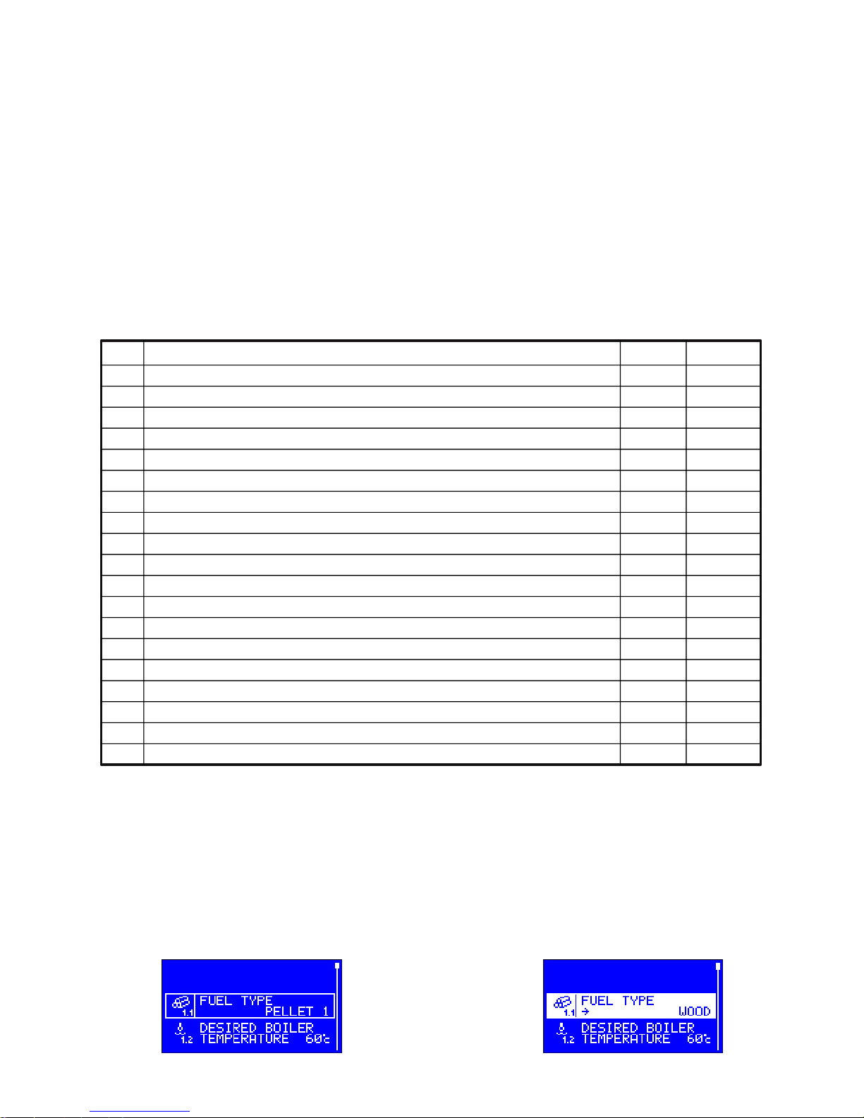
1.1 Fuel type. 1 4
1.2 Desired boiler temperature. 40°C 90°C
1.3 Boiler max. power. 60% 100%
1.4 Central heating pump operation mode. WINTER SUMMER
1.5 Domestic water desired temperature. 30°C 60°C
1.6 Domestic water heating priority. NO YES
1.7 Domestic water tank bacterial flora liquidation program. NO YES
1.8 Measured domestic water temperature.
1.9 Measured return water temperature.
1.13 Current furnace brightness (FD–1).
1.14 Ignitor turn-off depending on the illuminance value. 0 255
1.10 Temperature of the burner (PT–1000, CT–1/2).
1.11 Ignitor turn-off depending on the temperature. 200°C 500°C
1.15 Burner running time.
1.16 Number of inflammation burner.
1.17 Boiler is turned on. NO YES
1.18 DHW heating is turned on. NO YES
1.19 Alarms cancellation.
1.20 Burner working mode. (CONTINUOUS), CYCLIC)
1.1 Fuel type selection.
RK-2006LPG controller enables programming ignition settings for four different fuel
types. „Fuel type” parameter enables switching between particular settings. Fan,
auger and igniter operation are saved for the selected fuel type.
PELLET 1,2,3 and WOOD. When the WOOD fuel is set, you can burn the wood in
the pellet boiler – the controller operates at the wood fuel burning settings.
WOOD/PELLET – once the wood has been burned, the controller switches to pellet
burning and full service to the pellet boiler is provided.
Page 13

13
CAUTION! Fuel type may be changed, if the controller is in STOP mode only.
1.2 Desired boiler temperature – it is the temperature setting that will be obtained
by the controller, if room thermostat input contacts are closed.
1.3 Boiler operation max. power.
Boiler operation max. power – this parameter enables to limit boiler operation max
power. Power limitation is possible thanks to fuel reduction during operation at
maximum power.
1.4 CH pump work mode – WINTER/SUMMER – you can turn off the heating during summer by selecting the SUMMER value. The parameter indicates the CH
pump work will be turned off. When in the mode, the regulator controls the boiler to
feed the domestic hot water circulation
only.
1.5 Domestic water desired temperature – parameter that specifies temperature
of water in domestic water tank that will be obtained by the controller.
1.6 Domestic water heating priority – this parameter specifies operation of central
heating and domestic water pumps during hot water preheating. When priority is
selected during operation and hot water preheating, the controller engages domestic
water pump and switches off central heating pump. This operation results in quick
heating of water in the tank. During preparation of hot water without priority option,
central heating and domestic water pumps operation follow at the same time.
Page 14

14
1.7 Bacterial flora liquidation in domestic water tank – the controller enables
manual activation of program for bacterial flora liquidation in domestic water tank.
When „YES” is selected, it activates the process of heating the domestic water tank
above 75°C. When the required temperature is obtained the controller switches off
the bacterial flora liquidation program automatically.
CAUTION! Bacterial flora liquidation option shall be switched on in the night or if
water intake does not follow from the domestic water tank, to protect the user
against burning.
1.8 Domestic water measured temperature – the controller enables to view the
temperature measured in domestic water tank.
CAUTION! In case the heating system is not fitted with the DHW circuit, it is not
possible to view or change the above parameters.
1.9 Return water temperature.
If the heating circuit is equipped with the mixing pump and return temperature
sensor, this option enables view of the return water temperature. Otherwise, this
option in unavailable.
Flame optical detection parameters.
These parameters specify operation of burner flame optical detector. If the system is
fitted with flame temperature detector, parameters change and viewing is
unavailable.
1.13 The current furnace brightness determined by an optical detector – this
parameter displays the current flame brightness measured by the optical detector.
Page 15

15
1.14 Brightness when fuel ignition has occurred – if the optical detector reading
will be equal or higher than this desired setting, the controller will switch off the
igniter and assume that ignition has occurred.
Flame detection temperature parameters.
These parameters specify operation of the temperature detector of burner fuel
ignition. If the system is fitted with optical fire burner detector, parameters change
and viewing is unavailable.
1.10 Burner measured temperature – this parameter displays the current measured burner temperature.
1.11/1.12 Burner temperature with fuel ignited - if ignition temperature is equal or
higher than this desired setting, the controller will switch off the lighter and assume
that ignition was provided.
Information on burner work.
Parameters described below refer to counters that accumulate information on
operation of the burner since its first start. It is not possible to cancel counter
readings.
1.15 Burner work time.
Reading of this counter defines burner work time. The counter updating follows after
total working hour of the device at maximum or minimum power.
1.16 Burner start up counter.
Reading of this counter defines start number of the ignition attempts.
1.17 Boiler on.
The parameter informs the user if the boiler is turned on and allows him/her to turn it
on or off.
Page 16

16
1.18 DHW heating on.
The parameter informs the user if the DHW heating is turned on and allows him/her
to turn it on or off.
1.19 Alarms cancellation.
The parameter enables the user to cancel the alarms recorded in the controller data
storage.
1.20 Burner mode.
CYCLIC – turning off the thermostat will cause the controller to switch into the
POSTCOMBUSTION mode.
CONSTANT – once the thermostat is turned off, the controller will switch into the
MINIMUM CAPACITY mode instead of the POSTCOMBUSTION (the mode saving
the ignitor).
6. Setting the parameters – service mode.
Service parameters are divided into groups. For each group are assigned
service parameters possible to change. Entry into service mode after press and hold
for about 3 seconds the MENU button. regulator displays a list of service parameters
possible to edit and change.
Viewing the list of parameters is possible by turning the multifunction knob - possible
to edit the parameter is highlighted. After selecting the desired parameter press the
OK button (knob), and enter the subgroups of a given parameter. Select the parameter you want to change and press the knob - a parameter is highlighted. Turning the
knob set the desired value and then press the knob. Giving up mode changes and
restore the previous value of the parameter by pressing the STOP button or ESC. If
the unit is left in a mode change or view the parameters for 60 seconds, the controller will automatically withdraw the recently introduced modification and switch to display the status of the device. A list of all service parameters presented in the table.
The table columns contain the following order: group number, name of the parameter and the value of the minimum and maximum possible settings.
Page 17

17
Table 3. Table service parameter.
Lp.
Parametr Min Max
2.x
Overall
2.1 Language. (see description)).
2.2 Brightness of the display.
2.3Saturation.
2.4 Contrast.
2.5 Service settings. NO YES
2.7 Output testing. NO YES
3.x
Fan
3.1 Fan modulation during boiler start. NO YES
3.2 Min. fan speed during heating up. 1% 100%
3.3 Max. fan speed during heating up. 1% 100%
3.4 Ignition modulation start delay. 0s 250s
3.5 Fan speed during ignition. 1% 100%
3.6 Fan speed at max. power. 1% 100%
3.7 Fan speed at min. power. 1% 100%
3.8 Fan speed at extinction. 1% 100%
3.9 Fan speed during cleaning mode. 0% 100%
3.10 Fan scavenge (air purging). NO YES
3.11 Fan scavenge (air purging) blow time. 5s 60s
3.12 Fan scavenge (air purging) pause time. 1min 99min
3.13 Fan speed during scavenge. 1% 100%
4.1 Auger filling tim. 1min 99min
4.2 Initial fuel feed. 0s 250s
4.3 Fuel feed cycle. 1s 250s
4.4 Fuel feed during ignition. 0% 100%
4.5 Fuel feed for max burner power. 1% 100%
4.x
Auger
4.6 Fuel feed for min. burner power. 1% 100%
4.7 Stoker work mode (See description).
4.8 Stoker work time. 1s 99s
4.9 Stoker pause time. 1s 99s
4.10 Stoker extra work time. 1s 99s
4.11 Stoker emptying time. 1s 99s
4.12 Auger ignition test. NO YES
4.13 Auger ignition temperature. 20°C 99°C
5.x
Igniter
5.1 Flame detector type: FD–1, PT–1000, CT–1/2.
5.2 CorrectionFD–1. 0 99
5.3 Hysteresis loss of flame (temperature sensor). 1°C 250°C
5.4 Hysteresis loss of flame (optical sensor). 1 255
5.5 Flame failure detection delay. 1s 500s
5.6 Fuel ignition timea. 1min 15min
5.7 Ignition try count. 1 10
5.10 Firing stabilization. NO YES
5.11 Stabilization time firing up. 1min 99min
5.12 Smooth stabilization firing. 1min 99min
5.13 The blanking time the furnace. 1min 30min
5.15 Blower at pellet burning mode.
5.16 Blower at the wood burning mode.
6.x
Cleaning
mechanism
6.1 Mode of operation of the cleaning mechanism: CYCLE,
ROTO, AUTO, COMBI, COMBI2
6.2 Cleaning mechanism work time. 1s 900s
6.3 Cleaning mechanism retraction time. 1s 900s
6.4 Cleaning mechanism pause time. 1s 900s
6.5 Opening time cleaning mechanism. 1s 900s
6.6 Closing time cleaning mechanism. 1s 900s
6.7 Number shut downs before cleaning. 1
99
Page 18

18
6.8 Minimum operating time without cleaning. 0h max–1h
6.9 Maximum working time without cleaning. min+1h 99h
7.x
CH pump
7.1 Central heating pump work mode: TERM, AUTO.
7.2 Central heating pump periodic work. NO YES
7.3 Central heating pump periodic work time. 1min 99min
8.x
HTW pump
8.1 Domestic water path: OFF, ON, MIXING PUMP,
8.2 Domestic water heating hysteresis. 1°C 20°C
8.3 Boiler increase temperature during hot tap water heating. 2°C 20°C
8.4 Domestic pump work extension. NO YES
8.5 Domestic pump work extension time. 1min 10min
8.6 Stabilization time. 1min 99min
8.7 Mixing pump engaging temperature. 30°C 60°C
8.8 Mixing pump work hysteresis. 1°C 9°C
9.x
Thermostat
9.1 Boiler minimum temperature. 30°C 69°C
9.2 Boiler maximum temperatur. 70°C 90°C
9.3 Boiler upper hysteresis. 1°C 20°C
9.4 Boiler power switching hysteresis. 1°C 9°C
9.5 Boiler protection hysteresis. 1°C 5°C
9.6 Boiler overheating temperature. 90°C 99°C
9.7 Burner power modulation. NO YES
9.8 Modulation factor. 1 20
9.9 The operating mode of the thermostat: NORM, ADAP.
9.10 The time constant adaptation. 1min 99min
9.11 Burner off delay. 0min 99min
10.x
Data
transmission
10.1 Data link: (see description). OFF, MODBUS RTU.
10.2 MODBUS device number. 1 247
10.3 MODBUS channel capacity: 2400, 3600, 4800, 7200,
9600, 14400, 19200, 28800,38400, 56000, 57600, 76800,
115200.
10.4 MODBUS frame format: 8N1,8E1, 801, 8N2.
10.5 MODBUS access level: NONE, READOUT,
USER’s, SERVICE.
10.6 Terminal access level: NONE, READOUT,
USER’s, SERVICE.
11.x
Fan 2
11.1 Blower 2; ON, NONE.
11.2 Modulation of blower speed rate at ignition. NO YES
11.3 Minimum blower speed at ignition. 1% 100%
11.4 Maximum blower speed at ignition. 1% 100%
11.5 Modulation turn-on latency at ignition. 0s 250s
11.7 Blower speed rate at the maximum capacity. 1% 100%
11.8 Blower speed rate at the minimum capacity. 1% 100%
11.9 Blower speed rate at extinction. 1% 100%
11.10 Blower speed at cleaning. 1 247
11.11 Blower draught. NO YES
11.12 Draught duration. 5s 60s
11.13 Silence between draughts duration. 1min 99min
11.14 Blower speed at draught. 1% 100%
12.x
Emergency
power system
12.1 Power supply malfunction control: NONE,ON.
12.2 Turn-off latency. NO YES
12.3 Power supply shortage mode: POSTCOMBUSTION,
CLEANING
12.4 CH pump work NO YES
12.5 DHW pump work NO YES
Page 19

19
2.x Overall.
2.1 Language selection.
RK-2006LPG2 controller interface offer the function of language selection. Number
of available languages depend on software version being used.
2.2–2.4 Brightness, saturation, contrast of the display.
The parameters enable the user to adjust the display to his/her own needs.
2.5 Service settings – setting and confirm with the OK button to display the value
YES when this option will delete all the parameters and assign them to the pre-programmed by the installer or service technician.
2.7 Testing out.
In order to verify the correctness of the controller, it is possible to test various output
devices. This feature is available in service mode only if the adjustment process is
stopped, ie. The regulator before entering the service mode was in STOP mode.
Selecting output testing allows the control knob to select the outputs on the display.
Pressing OK allows you to temporarily attach the selected output. In order to
complete the testing procedures exit, press the STOP button.
Page 20

20
3.x Fan operation parameters.
3.1 Fan modulation during boiler start – selection of „YES” setting means that fan
speed modulation will be provided during boiler start.
3.2 Min. fan speed during heating up – this parameter is available, if the function
of fan modulation during boiler start is selected. This parameter specifies power of
the fan during boiler start.
3.3 Max. fan speed during heating up – this parameter is available, if the function
of fan modulation during boiler start is selected. This parameter specifies power of
the fan at end of boiler start.
3.4 Ignition modulation start delay – this parameter is available, if the function of
fan modulation during boiler start is selected and it describes operation time of the
fan with speed according to the selected „Min. fan speed during boiler start” setting.
After time expire the controller will increase fan speed up to the selected „Max. fan
speed during boiler start” setting.
3.5 Fan speed during ignition – this parameter describes power of the fan speed
during ignition. This parameter is unavailable if „Fan speed modulation during
ignition” was selected.
Page 21

21
3.6 Fan speed at max. power – means the fan power when burner of the boiler
works with maximum power.
3.7 Fan speed at min. power – means the fan power when burner of the boiler
works with minimum power.
3.8 Fan speed during extinction (shut down) – means fan power during burner
extinction (shut down).
3.9 The fan speed for cleaning – this parameter is available only when the
cleaning mechanism operates in AUTO mode or COMBI. It specifies that the power
of the fan while cleaning the hearth.
3.10 Fan scavenge (air purging) – the controller offers the function of scavenge
(air purging), which simply includes periodical switching on of the fan during burner
operation for the purpose of removal of accumulated gases.
3.11 Fan scavenge (air purging) blow time – this parameter specifies blow time.
This setting is unavailable if „Fan scavenge” (air purging) setting was not selected.
Page 22

22
3.12 Fan scavenge (air purging) pause time – this parameter specifies pause time
during scavenge. This setting is unavailable if „Fan scavenge” (air purging) setting
was not selected.
3.13 Fan speed during scavenge (air purging) – this parameter specifies fan
power during scavenge (air purging). This setting is unavailable if „Fan scavenge”
(air purging) setting was not selected.
4.x Fuel auger operation parameters.
4.1 Auger filling time – this parameter specifies time required for refilling the main
auger with fuel.
4.2 Initial fuel feed – this parameter specifies time, when fuel will be fed before
igniter start. Selection of „0s” setting will switch off initial fuel dose feeding. In this
case „Fuel dose during ignition” setting shall be programmed as the value over „0%”.
4.3 Fuel feed cycle – auger operation cycle includes fuel feeding and feeding
pause. This parameter specifies the time of the whole cycle. The desired value
specifies all burner work modes which require fuel feeding (ignition, maximum and
minimum power).
Page 23

23
4.4 Fuel feed during ignition – this parameter specifies fuel dose that is fed to the
burner during lighter operation. The programmed setting specifies feeding time in
percent in relation to the time of whole work cycle. Selection of „0s” setting will
switch fuel feeding during operation of the lighter. In this case „Initial Fuel Dose”
setting be shall be programmed as the value over „0s”.
4.5 Fuel feed for max. burner power – this parameter specifies fuel dose fed to the
burner during operation with maximum power. The programmed setting specifies
feeding time in percent in relation to the time of whole work cycle.
4.6 Fuel feed for min. burner power – this parameter specifies fuel dose fed to the
burner during operation with minimum power. The programmed setting specifies
feeding time in percent in relation to the time of whole work cycle.
4.7 Stoker work mode – This parameter defines the operation of the internal tray
(stoker):
OFF – the burner without the stoker.
CYCL – stoker is switched on periodically, regardless of the auger. Work and pause
time of the stoker is determined with particular settings.
AUTO – operation mode when the stoke is switched on along with the auger and is
switched off with a delay defined with „Stoker extra work time” setting.
Page 24

24
4.8 Stoker work time – this parameter specifies operation time of the stoker in
whole work cycle. This setting is unavailable if the stoker is switched off or in
automatic mode.
4.9 Stoker pause time – this parameter specifies pause time during stoker
operation when in work cycle. This setting is unavailable if the stoker is switched off
or in automatic mode.
4.10 Time to extend the work stoker – this parameter is only available when stker
is in automatic mode and determines how long after you turn off the main tray will
work stoker.
4.11 Stoker emptying time – this parameter specifies time needed for removal of
the whole fuel from the stoker. Stoker emptying during extinguishing of feeder,
feeding initial fuel dose (portion), and during burner shut down. This setting is
unavailable if the stoker is switched off.
4.12 Auger ignition test – this parameter provides functionalities of „X” emergency
input. If „NO” setting was selected then „X” input will be used for connection of e.g.
auger flap opening contact sensor or the contact informing on operation of auger
motor overload switch. If „YES” setting was selected then „X” input will be used for
connection of auger temperature sensor used for ignition detection.
Page 25

25
CAUTION! In case emergency input is not used, „NO” parameter shall be selected
in „Auger ignition test” setting and contacts of „X” input shall be closed.
4.13 Auger ignition temperature – this parameter specifies auger temperature,
when the controller activates auger ignition alarm. This parameter is unavailable
when „NO” was selected in „Auger ignition test” setting.
5.x Ignitor working parameters.
5.1 Flame detector type – FD–1/ CT–1/2/ PT–1000 – flame detection may follow
with two methods: burner temperature measurement or brightness measurement. In
case when temperature sensor is used, depending on its location, temperature
measurement range may be from several degrees to several hundred degrees. If
measured temperatures do not exceed 100°C it is recommended to use CT-1 or
CT-2 sensor. In case of higher temperatures, PT-1000 sensor shall be used. For
flame brightness measurement, FD-1 optical detector shall be used.
5.2 Indication correction of flame optical detector – only when flame optical
detector (FD-1) is on. Describes light intensity detected by optical detector when
burner is off. The correction value is deducted from the value light intensity during
the flame detection. Correction allows calibration of FD-1 sensor the way that during
burner shut down value (no flame) of the light equals zero.
5.3–5.4 Hysteresis loss of flame – depending on the type of flame detector, this
parameter specifies how many degrees or units in relation to the threshold set by the
user must cut off the lighter or the brightness of the flame temperature to the
controller began to flame failure detection procedure.
Page 26

26
WARNING! If the hysteresis is larger than the threshold of igniter shut down, flame
failure detection procedure is started when the temperature drops or the brightness
of the flame to the value of „0”.
5.5 Flame failure detection delay – this parameter specifies how long after the
launch procedures for the detection of flame failure or brightness temperature must
remain below the hysteresis for the regulator to decide that the furnace was
extinguished.
5.6 Fuel ignition time – after igniter and fan are switched on, the controller tests
temperature increase or brightness in the selected location of the burner. If flame is
not detected within the time programmed in this parameter, the controller will repeat
ignition cycle.
5.7 Ignition try count – this parameter specifies how many times ignition may fail
until the controller activates „Out of fuel alarm” and switches into STOP mode. The
alarm is indicated with adequate message displayed on the display. To start the
controller first refill the fuel, then cancel by pressing STOP button and start setting
mode by pressing START button.
5.10 Firing stabilization – this parameter determines whether the fuel kindling
Stabilization mode is enabled firing.
5.11 Firing stabilization time – this parameter determines the maximum operating
time of stabilization firing. This parameter is not available if the parameter
STABILIZATION OF FIRING is set to NO.
Page 27

27
5.12 Smooth stabilization of ignition – setting the parameter to YES will cause the
stabilization of firing up the controller gradually increases the amount of fuel fed.
This parameter is not available if the parameter STABILIZATION OF FIRING is set to
NO.
5.13 Furnace extinction (shut down) time – if the controller switches to extinction
(shut down) mode, the induction fan is activated according to power selected in „Fan
speed at extinction (shut down)” setting. After burner extinction (flame loss), the fan
operation follows according to time programmed in this setting. This function
ensures combustion of all fuel remains and burner cool down.
5.15 Blower at pellet burning mode – the parameter enables the user to switch an
additional blower.
5.16 Blower at the wood burning mode – the user can determine which blower will
be operating when the wood will be burned. You can select either the blower 1 or an
additional blower 2, or both.
Page 28

28
6.x Cleaning mechanism.
6.1 Furnace cleaning mode – this parameter specifies the way the cleaning
mechanism works:
NONE – means that the burner does not have a cleaning mechanism. In this case,
the output DATA is working as an external alarm.
CYCL – means the mode in which the cleaning procedure is run after the firing and
repeated at regular intervals until burner shut down is completed. Cleaning
procedure is attached to the time set in parameter „Cleaning mechanism work time".
After turning off the regulator, output deducts the time set in parameter „Cleaning
mechanism retraction time" and the time set in parameter „Cleaning mechanism
pause time".
ROTO – working mechanism ROTO mode is similar to mode CYCLE. The difference
is that the control output cleaning mechanism is attached for the duration of the
mode blanked.
AUTO – means the cleaning procedure is started automatically after a specified
number shut downs or after a sufficient burner operation time. Automatic cleaning
means: burner shut down and start cleaning mechanism for the time set in parameter
„Cleaning mechanism work time".
After turning off the regulator, output deducts the time set in parameter "Cleaning
mechanism retraction time" and then goes to normal working cycle.
COMBI – This mode is a combination of modes AUTO CYCLE. Working mechanism
starts at the end of the firing and stabilization is cyclical switching mechanism for the
time set in the parameter TIME WORK MECHANISM. After switching off the cleaning
mechanism controller counts down the time set in parameter RETURN TIME
MECHANISM, and the time set in parameter TIME PARKING MECHANISM. During
operation the output EXTINCTION cleaning mechanism is disabled. After a certain
number of extinctions or sufficient time, the burner is started automatically cleaning
involving extinguished hearth, start cleaning mechanism at the time set in the
parameter TIME OPENING THE MECHANISM and run the fan with the power
specified in the parameter SPEED FAN. THE CLEANING.
After switching off the engine output controller also disables the fan and counts
time set in the parameter TIME CLOSING MECHANISM, then take a normal job.
Page 29

29
COMBI 2 – a mode similar to COMBI; the difference is that when the clearing device
is turned on, the blower always operates with the capacity programmed in the parameter BLOWER SPEED RATE AT CLEANING, regardless of the current stage of
operations (except emergencies).
6.2 Cleaning mechanism work time – this parameter is available only when the
cleaning mechanism is activated (CYCLE, ROTO or COMBI. mode). It defines the
time needed to complete the full mechanism to open or move to end position.
6.3 Cleaning mechanism retraction time – this parameter is available only when
the cleaning mechanism is activated (CYCLE, ROTO or COMBI. mode). It specifies
the time required for the mechanism retraction to the rest position after turning off
the control output.
6.4 Cleaning mechanism pause time – this parameter is available only when the
cleaning mechanism is activated (CYCLE, ROTO or COMBI. mode). It specifies the
time interval between successive repetition of the cleaning cycle.
6.5 Opening time cleaning mechanism – this parameter is only available when
cleaning mechanism operates in AUTO mode or ESTATE and determines the time
required to complete the opening mechanism during cleaning automatic.
6.6 Closing time cleaning mechanism – This parameter is available only when the
cleaning mechanism operates in AUTO mode or COMBI and determines the time it
takes to return the mechanism to its rest position after the full opening of the
automatic cleaning mechanism.
Page 30

30
6.7 Number of extinctions before cleaning – this parameter is available only when
the cleaning mechanism operates in AUTO mode or COMBI and determines which
in turn goes off to start the procedure of cleaning.
6.8 Minimum operating time without cleaning – this parameter is available only
when the cleaning mechanism operates in AUTO or COMBI mode. Specifies the
minimum number of hours the burner must in order to start cleaning. If the minimum
time is not reached, the cleaning will not run even if there was a required number of
shut downs. Setting the parameter to „0h" control the minimum time off work without
cleaning.
6.9 The maximum working time without cleaning – this parameter is available
only when the cleaning mechanism operates in AUTO or COMBI mode. Specifies
how many hours the burner can work without cleaning. If the maximum time is
reached, the cleaning will run even if there was no required number of shut downs.
7.x Central heating pump work parameters.
7.1 Central heating pump switching on parameters – this parameter specifies the
method of central heating pump switching on. Selection of „THERMOSTAT” setting
means that central heating pump will be switched on only if room thermostat
contacts are closed and in case of emergency (e.g. boiler overheating). Selection of
„AUTO” setting means that central heating pump operation will follow regardless of
room thermostat.
7.2 Periodic switching pump – this parameter allows you to run the function
periodic heating pump to move water in the heating circuit. The pump is activated for
30 seconds at intervals set in the parameter TIME PERIOD. ON. PUMP CO. This
function is available when the CO pump mode is set to the value of TERM.
Page 31

31
7.3 CH pump periodic work time – this parameter is available, if CH pump works in
„THERMOSTAT” mode and the function of CH pump periodic work is active. The
programmed setting will specify the time lapse between CH pump work, in case of
opened contacts of the room thermostat.
8.x Setting domestic water pump parameters – NO, IS, Mixing pump
The controller offers an additional function for heating of domestic water. Not every
heating system is provided with domestic water tank and charge pump, this circuit
may be switched off or used for control of the pump that mixes the return water in
the boiler.
8.1 Domestic water path – if „NONE” is selected the domestic water pump is off. In
this case temperature sensor input and pump control output may remain
disconnected. Selection of „EXISTS” setting provides for interlock release of all
parameters and functions related to domestic water path handling. Election of
„MIXING PUMP” setting will switch domestic water in the circuit purposed for control
of the mixing pump. In this case return water temperature sensor shall be connected
instead of domestic water sensor, and the mixing pump instead of charge pump of
domestic water tank.
8.2 Domestic water heating hysteresis – this parameter indicates water
temperature drop in the tank in relation to the programmed setting (so that charge
pump was switched on). This setting is available, if domestic water path „EXISTS”
setting was selected.
Page 32

32
8.3 Increase temperature during domestic water heating – Closing thermostat
contacts means that boiler operation will follow according to the temperature
programmed with the thermostat knob. If domestic water tank heating is necessary,
the desired boiler temperature is higher in relation to the desired domestic water by
the selected value in this setting. In case of simultaneous operation of the room
thermostat and domestic water tank heating, the controller operation will follow to
maintain the higher boiler temperature. This setting is available, if domestic water
path „EXISTS” setting was selected.
8.4 Domestic water pump work extension – quick switching off of the pump
refilling domestic water tank may result in excessive rise of boiler temperature. This
parameter enables switching on of domestic water pump extension. This setting is
available, if domestic water path „EXISTS” setting was selected.
8.5 Domestic water pump extension time – this parameter specifies the time lapse when domestic water is switched off since the moment when the programmed
temperature of domestic water tank was obtained. This setting is available, if domestic water path „EXISTS” setting was selected and pump extension was selected.
8.6 The stabilization time after heating hot water – during the preparation of hot
water priority enabled all the power boiler is used to heat water. Temperature of the
boiler during operation for hot water is often higher than the required heating circuit.
In addition, the CH pump off when working with hot water priority can cause
hypothermia heated rooms and a room thermostat input activation. In this case, after
working for the hot water boiler water temperature may be higher than the
temperature required to heat the rooms. This may result in extinction of the burner
due to exceeding the hysteresis top of the boiler. This parameter specifies how long
is needed to stabilize the system after the hot water tank with priority enabled.
During the stabilization controller disable checking hysteresis top and suspend the
operation of the adaptive algorithm of the room thermostat. This parameter is
available only when hot water is on track.
Page 33

33
CAUTION! This feature does not work if water preparation is done without priority or
the controller is in summer mode.
8.7 Mixing pump engaging temperature – this parameter specifies required return
water temperature so that the mixing pump engagement follows the controller. This
parameter is available if domestic water path „MIXING PUMP” setting was selected.
8.8 Mixing pump work hysteresis – this parameter specifies required return water
temperature increase in relation to the mixing pump engagement temperature so
that the controller switches off the mixing pump. This parameter is available if
domestic water path „MIXING PUMP” setting was selected.
9.x Boiler work parameters.
9.1 Minimum boiler temperature – this parameter specifies boiler temperature
when the controller shall switch off central heating and domestic water pumps. It is
the lowest temperature setting of the boiler that can be programmed with
thermostat’s knob.
9.2 Maximum boiler temperature – this parameter specifies boiler max.
programmed temperature setting which can be programmed with thermostat’s knob.
It is also boiler temperature when central heating pump is engaged to provide
protection for the boiler against overheating.
9.3 Boiler upper hysteresis – if the controller works in burner minimum power
mode, and boiler temperature increase follows by this programmed setting, the
controller will start burner extinction(shut down).
Page 34

34
9.4 Burner power switching hysteresis – when the programmed boiler water
temperature is obtained the controller is switched to minimum power work mode.
This parameter specifies required water temperature drop so that maximum power
work mode was activated. After switching to maximum power the fuel and air feeding
dose is determined according to burner power modulation.
9.5 Boiler protection hysteresis – the controller provides for boiler minimum and
maximum temperature by providing control over operation of central heating and
domestic water pumps. This parameter specifies hysteresis parameter of boiler limit
temperatures switching off.
9.6 Boiler overheating temperature – this parameter specifies boiler water
temperature when the controller switches off control and activates boiler overheating
alarm.
9.7 Burner power modulation – when modulation is switched on it will results in
gradual reduction of fan speed and fuel dose to obtain boiler water temperature
corresponding to the programmed setting.
9.8 Burner power modulation factor – this parameter specifies degree setting
when the controller will reduce burner power before boiler water temperature is
obtained according to the programmed setting. Burner power is reduced by gradual
reduction of fed fuel dose and fan speed reduction. This parameter is unavailable, if
burner modulation power is off.
Page 35

35
The room thermostat.
RK-2006LPG2 was equipped with an input for connecting any room thermostat with
contact output. Contacts of the thermostat is signaled by the appearance of the
thermometer symbol in the index of the thermostat.
CAUTION! The entrance of the room thermostat is active only during WINTER.
Lights up when the input state is independent of the mode setting.
9.9 Mode of operation of the room thermostat – this parameter determines the
impact of the entry of the room thermostat to the operation of the controller:
NORM. – in this mode, the thermostat contacts are closed when the controller starts
firing up the burner and the boiler strives to maintain the set temperature of the
boiler thermostat knob. After reaching the desired temperature in the room and the
thermostat regulator contacts open burner extinguishes and goes STANDBY.
ADAP. – in this mode, the controller analyzes the changes in the thermostat input
and based on automatically determines the setpoint temperature of the boiler.
Caution! In the case of not using the room thermostat input should remain closed,
and the operation of the thermostat set to the NORM .. In this case, the boiler will
operate continuously maintaining the set temperature of the boiler thermostat knob.
9.10 The time constant of adaptation – this parameter is available when the thermostat is working in adaptive mode. It determines the rate of "seeking" appropriate
adaptive algorithm preset boiler temperature. Value should be selected empirically
according to the characteristics of the controlled object. If you are working adaptive
algorithm and frequently changing external conditions we observe frequent overheating of the rooms, increase the time constant. During niedogrzewania value should
be reduced.
9.11 Burner off delay – this parameter determines the time of the burner in
minimum power the thermostat contacts open. If, after the programmed time the
thermostat input will not be closed again, the torch will be lit, and the controller switches to STANDBY. Setting this parameter to 0 minutes will immediately extinguish
the torch after contact opening
thermostat.
Page 36

36
CAUTION! If the controller works well for hot water, the burner after contact opening
the thermostat can be switched off after a time other than that programmed in the
parameter.
10.x Data transmission.
10.1 Data link – the parameter allows the user to select the operation performed by
the data connector.
NONE – connector inactive (default value).
MODBUS RTU – Communication by RS-485 bus with using the ModBus standard
RTU protocol.
10.2 MODBUS device number – 1..247 – allows the user to determine the number
of the device attributed to your controller, and to avoid errors when a number of
devices are switched to the bus. Default value -1.
10.3 MODBUS channel capacity – selection of the RS-485 transmission speed.
Default value – 38400.
10.4 MODBUS frame format – allows you to determine the data frame format used
in the RS- 485 transmission.
8N1 – 8 bits of data, no parity bits, 1 bit of silence.
8E1 – 8 bits of data, even parity bit, 1 bit of silence.
8O1 – 8 bits of data, odd parity bit, 1 bit of silence.
8N2 – 8 bits of data, no parity bits, 2 bits of silence (default setting).
Page 37

37
10.5 MODBUS access level – defines to what extent the configuration of
parameters is available to the ModBus protocol.
NONE – no parameters are provided by the controller.
READ-OUT – the controller allows you to view its parameters only.
USER – changing the user’s parameters only is available (default setting).
SERVICE – changing all of the parameters is possible.
10.6 Terminal access level – defines to what extent access can be obtained
through the remote terminal.
NO – no access through the remote terminal.
READ-OUT – terminal allows you to view the parameters and controller work only.
USER – it is possible to change the parameters user’s settings (default settings).
SERVICE – full access to the controller and viewing all of the parameters can be
obtained through the terminal.
Page 38

38
11.x Additional blower.
11.1 Blower 2 – to use an additional blower, change value of the parameter to ON.
12.x Emergency power system.
Power supply malfunction control – to ensure continuity of work, the controller
has been equipped with the power supply malfunction control. When the power
system has been equipped with uninterruptible power supply and the power supply
malfunction detector, the controller will switch to uninterruptible power supply when
malfunction occurs.
12.2 Turn-off latency – is the period after which (when power supply malfunction
occurs) the controller will switch into the emergency mode and will be not responsive
to short-lived power supply malfunctions.
12.3 Power supply shortage mode – POSTCOMBUSTION, CLEANING – when
the controller has switched to the emergency mode, it will start cleaning or
postcombustion and cleaning processes after the period set in TURN-OFF
LATENCY parameter.
12.4 CH pump work – the parameter defines, if the CH pump will work in the emergency mode.
Page 39

39
12.5 DHW pump work – the parameter defines, if the DHW pump will work in the
emergency mode.
12.6 Mixing pump work – the parameter defines, if the mixing pump will work in the
emergency mode.
4. DATA emergency output – audible alarm or cleaning mechanism.
The regulator has output [D] allows you to connect via the UM-1 module siren alarm
or additional cleaning mechanism. If you exit this mode, the siren is in alarm, it is
activated in the event of: sensor failure of the boiler, burner sensor, the sensor or
mixing pump hot water, boiler overheating or lack of fuel.
5. Controller disassembly.
If controller disassembly is necessary follow the following procedure:
– Disconnect the boiler and controller from power supply,
– Remove the controller from the boiler,
– Disconnect terminals and wires from the controller.
6. Technical Data.
Power Supply 230 V ± 10%, 50 Hz
Power consumption (without fan and pump) < 4 VA
Burner temperature measurement range (KTY 81-210) -9–109°C±1°C
Temperature measurement range (KTY 81-210) -9–109°C±1°C
Burner temperature measurement range (PT-1000) -30–500°C±3°C
Boiler temperature adjustment range 30–90°C±1°C
Boiler programmed overheating protection 90–99°C±1°C
Boiler equipment overheating protection >95°C±1°C
Total outputs rating max 4 A / 230 V
Dimensions (H x W x D) 96 x 144 x 94
Page 40

40
Page 41

41
Page 42

42
Page 43

DECLARATION OF CONFORMITY
Manufacturer:Przedsiębiorstwo Wielobranżowe KEY
11-200 Bartoszyce, ul. Bohaterów Warszawy 67
hereby declares that the product:
RK-2006LPG2 Controller
the essential requirements of
EC directive on electrical equipment for use within
certain voltage limits 2014/35 / UE (LDV) from 02/26/2014
and the
EC Electromagnetic Compatibility Directive 2014/30 / UE
equivalent (EMC) from 26.02.2016.
Applied harmonized standards:
EN 60730-1:2000 (PN-EN 60730-1:2002)
EN 60730-2-9:2010 (PN-EN 60730-2-9:2011)
EN 61000-3-2:2006 (PN-EN 61000-3-2:2007)
EN 61000-3-3:2008 (PN-EN 61000-3-3:2011)
EN 55022:2010 (PN-EN 55022:2011)
Information on disposal
This appliance is marked according to the European Directive 2002/96/EC on Waste
Electrical and Electronic Equipment (WEEE).
The symbol on the product, or the documents accompanying the product, indicates that
his appliance may not be treated as household waste.
The appliance shall be handed over to the applicable collection point for used up
electrical and electronic equipment for recycling purpose.
Ultimate disposal of the appliance shall follow according to applicable local regulations
on waste utilization. For more information about disposal, utilization and recycling please
contact your local authorities, household waste disposal service or the shop where you
purchased the product.
Page 44

Manufacturer: Przedsiębiorstwo Wielobranżowe KEY
11-200 Bartoszyce, ul. Bohaterów Warszawy 67
tel. (89) 763 50 50, fax. (89) 763 50 51
www.pwkey.pl e-mail:pwkey@onet.pl
 Loading...