

Page 1
OPERATING MANUAL
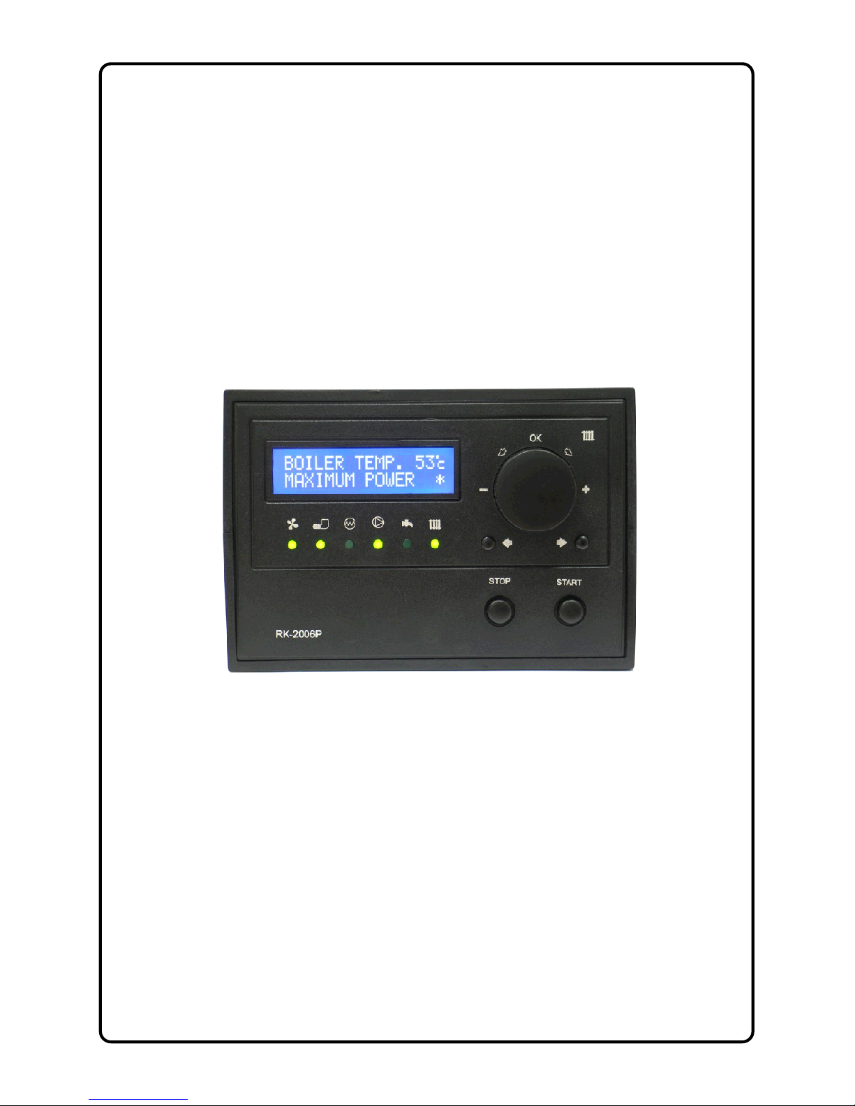
RK-2006LP
AUGER FITTED SOLID FUEL
BOILER TEMPERATURE CONTROLLER
Version DC19
Page 2

Page 3

3
1. Application.
Controller RK-2006LP is designed for temperature control of solid fuel fired water
boilers equipped with:
- Auger and feeding stoker working with the stoker,
- Blow-in fan,,
- Ignition glow plug for automatic start,
- Central heating pump,
- Hot tap water pump or mixing pump (option),
- Alarm indicator or ash removal system (option),
- Room termostat (option).
2. Connection.
Before turning on the controller, connect: power cables of: controller, blow-in fan,
central heating and hot tap water pumps and auger to appropriate sockets in the
rear of the controller. The temperature sensor should be placed in metering locations
that shall be dry. Figure 2 presents the electrical connection diagram. For connection
of stoker, alarm indicator and ash removal system the additional module UM-1 shall
be applied.
CAUTION! Before plugging in the controller first check if the wiring system is
properly grounded, and if the terminal screws of the output connector are tightened.
CAUTION! Total power of the fan, central heating and hot water pump which are
connected to the controller must not exceed 900W. Outputs of the controller that are
not used may remain disconnected.
CAUTION!!! Control outputs of the feeder and lighter are not protected and
MUST BE protected with adequate fuses.
CAUTION! The controller is equipped with properly protected semiconductor
temperature sensors, yet metering locations with installed sensors must be dry.
Page 4
4
3. Operation.
After turning the controller on, the name and software version is displayed and all
signal lamps are on to enable checking of functionalities. When the controller is turn
on it will return to its last state before turning off or power failure.
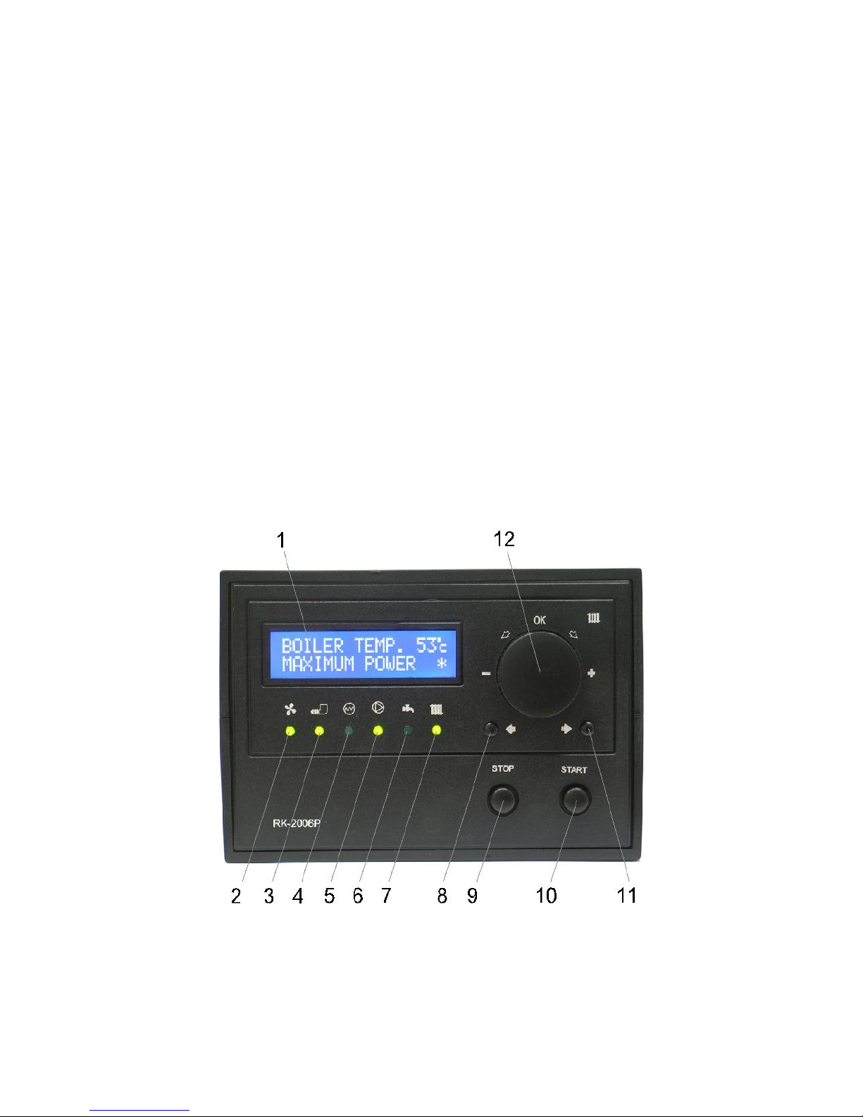
On the front panel of the controller (picture 1) there is:
1 - Display,
2 - Fan indicator,
3 - Auger indicator,
4 - Ignition glow plug indicator,
5 - Central heating circuit pump indicator,
6 - Hot tap water pump or mixing pump indicator,
7 - Room thermostat operation and boiler desired setting indicator,
8 - Previous parameter selection button,
9 - STOP button for alarm and settings change cancellation,
10- START button,
11- Next parameter selection button,
12- Boiler thermostat and parameters setting knob with OK confirmation button.
Picture 1. Front panel of RK-2006LP controller.
Page 5

5
3.1. Main window, adjustment mode and devices mode.
Following turning on of the controller the main window is displayed. On the top of the
display (1) boiler water temperature is shown, and on the bottom operation mode is
displayed. Symbol „*” displayed in the right bottom corner indicates burner flame
detection. Lights below the display indicate particular outputs and when switched on
they indicate their operation.
B O I L E R T E M P . 6 7 c
S T O P *
Basic operation of the controller is carried out by setting the desired temperature of
the boiler. To do this turn the boiler thermostat knob (12) according to the desired
setting and confirm with OK button (Press the knob).
D E S I R E D B O I L E R
T E M P E R A T U R E → 5 8 c
CAUTION! When the household thermostat input works in the mode of adaptation,
any attempts to change the boiler programmed temperature may end with failure, i.e.
when the new value is confirmed, the change in the boiler programmed temperature
to the value resulting from the algorithm of adaptation is automatic.
CAUTION! If the heating system is fitted with the domestic water tank, boiler water
temperature controlled and maintained by the controller during tank preheating may
be higher than desired temperature setting programmed with thermostat knob.
Page 6

6
3.2. Device operation modes.
Table 1. Operation mode list.
Operation mode Description
STOP Boiler control stopped. Controller maintains central heating and domestic
water pump operation, but automatic ignition does not follow.
STANDBY Controller maintains central heating and domestic water pump operation. In
case of heat demand automatic ignition of boiler follows.
IGNITION Controller carries out automatic ignition of boiler.
KINDLE FIRE
STABILIZE
Controlling the fan and auger to support the burner operation.
MAXIMUM
POWER
Fan and fuel feeder operate to reach boiler maximum power.
MODUL. POWER Controller reduces fuel feeding as much as boiler water temperature
corresponds to the desired setting.
MINIMUM POWER Fan and fuel feeder is minimized to maintain fire.
SCAVENGE
(AIR PURGING)
Controller activates blower to ensure removal of accumulated gases.
POSTCOMBUSTION No demand for heat or cleaning the furnace is needed. The feeder is turned off
and the fuel is reheated until the flame dies down.
EXTINCTION
(SHUTDOWN)
Controller shuts down boiler operation.
CLEANING Burner cleaning.
AUGER (MANUAL)
REFILLING
Manual operation of fuel auger. Boiler control stopped. Controller maintains
central heating and domestic water pumps operation, but automatic ignition
does not follow.
AUGER EXTINCT
(EMERGENCY
SHUTDOWN)
Fuel ignition in auger channel. The controller empties ignited fuel from the
auger channel until temperature drops.
ALARMS Safety and temperatures sensors failure alarms.
STOP.
Controller maintains central heating and domestic water pumps operation only to
protect the boiler against overheating and auger channel ignition. Room thermostat
contacts closing(call for heat) and domestic water temperature drop do not result in
any action. Pressing START button (10) will result in switching the controller to
STANDBY mode.
STANDBY.
In this mode controller does not carry out any additional operation, until room
thermostat contacts close (call for heat) or domestic water temperature drop, the
boiler operation will focus on maintenance of temperature according to thermostat
setting programmed with the knob. If preheating of domestic water tank is necessary
and the desired boiler temperature setting is higher from domestic water
temperature setting the controller will follow higher setting. Pressing the STOP
button (9) will result in switching to STOP mode.
IGNITION.
Boiler controller is switched into IGNITION mode if demand for heat follows, and if
the controller did not detect the flame. During ignition the controller activates fan,
auger and igniter. Fuel and air feeding rate is adjusted by the technician. IGNITION
Page 7

7
mode follows till flame is detected. If the flame is not detected within the specified
time, the controller activates „Out of fuel alarm”. Pressing STOP button, exceeding
time limit for cleaning, thermostat contacts opening or if water temperature in
domestic water tank is obtained during operation in IGNITION mode will result in
switching of the controller into the POSTCOMBUSTION mode.
KINDLE FIRE STABILIZE.
After the flame has been detected the boiler burner is switched into the KINDLE
FIRE STABILIZE mode. While in the mode the fan operates with the maximum
power. The fuel dose given by the auger is the same as while at work with the
minimum power. Additionally, depending on the service settings, the fuel dose may
be increased gradually. KINDLE FIRE STABILIZE option is being carried out for the
period of time set in the service settings or till the moment the boiler reaches the
programmed temperature. Pressing STOP button, exceeding time limit for cleaning,
thermostat contacts opening or if water temperature in domestic water tank is
obtained during operation in the KINDLE FIRE STABILIZE mode will result in
switching of the controller into the POSTCOMBUSTION mode.
CAUTION! The KINDLE FIRE STABILIZE mode can be turned off by the technical
staff. In such case the controller is switched into the work with the maximum power
after the ignition cycle has been finished.
MAXIMUM POWER OPERATION MODE.
When in this mode the controller operates fuel auger and fan to ensure max. power
of the boiler. Fuel and air feeding rate is adjusted by the technician. Pressing STOP
button, exceeding time limit for cleaning, thermostat contacts opening or if water
temperature in domestic water tank is obtained during operation in MAXIMUM
POWER mode will result in switching of the controller into EXTINCTION
(SHUTDOWN) mode.
MODULATED POWER OPERATION MODE.
Depending on desired parameters the controller may gradually reduce fuel and air
rate feeding to reduce burner power, as much as boiler water temperature
corresponds to the programmed setting. Pressing STOP button, exceeding time limit
for cleaning, thermostat contacts opening or if water temperature in domestic water
tank is obtained during operation in MODULATED POWER mode will result in
switching of the controller into POSTCOMBUSTION mode.
MINIMUM POWER OPERATION MODE.
When in this mode the controller operates fuel feeding and fan operation to maintain
firing to ensure the minimum fuel consumption. Fuel and air feeding rate is adjusted
by the technician. If in spite of boiler minimum power, increase temperature follows
of water temperature in relation to the top hysteresis parameter setting, the controller
will be switched into EXTINCTION (SHUTDOWN) mode. When the boiler water
temperature drops below the desired setting it will result in switching of the controller
into „Maximum power operation mode”. Pressing STOP button, exceeding time limit
for cleaning, thermostat contacts opening or if water temperature in domestic water
Page 8

8
tank is obtained during operation in MINIMUM POWER mode will result in switching
of the controller into POSTCOMBUSTION mode.
SCAVENGE (AIR PURGING).
During the operation with minimum power output, the controller will activate flue
scavenge (purging) to ensure removal of accumulated gases. Scavenge (purging) is
provided with temporary fan operation in higher speed.
POSTCOMBUSTION.
In the mode the auger is turned off by the regulator. The fan power is not altered (it
works with same speed as when the POSTCOMBUSTION mode was turned off).
The POSTCOMBUSTION prolongs till the moment the flame dies down, after which
the regulator is switched into the EXTINCTION mode.
EXTINCTION (SHUTDOWN).
In this mode the fan power is changed to the value programmed by the technical
staff to ensure complete fuel combustion and the burner cool down. When
EXTINCTION (SHUTDOWN) is finished the controller is switched into CLEANING,
STANDBY or STOP mode, provided POSTCOMBUSTION, EXTINCTION
(SHUTDOWN) followed as a result of STOP button pressing.
CLEANING.
The automatic furnace cleaning is carried out if the extinction time has been
determined by the technician or the burner has been operating long enough. In the
mode, the cleaning mechanism is activated for the period preprogrammed by the
technician. If the STOP button has been pressed during the cleaning, the controller
will enter either the STANDBY or STOP mode.
AUGER (MANUAL) REFILLING.
User may activate auger manual refilling function. When device is in STOP mode,
press START and hold button for 5 seconds to start refilling. Refilling follows
according to the time programmed by the technician or until it is manually turned off
with STOP button.
AUGER EXTINCTION (EMERGENCY SHUTDOWN).
If the auger is equipped with a temperature sensor, a temperature increase above
the range programmed by the technician, it will result in activation of auger ignition
alarm. The controller turns off the fan and auger. If the burner is equipped with the
stoker, the device is switched additionally into AUGER EXTINCTION (EMERGENCY
SHUTDOWN) mode. During shut down the stoker is engaged for the time needed to
remove the ignited fuel from the stoker. In addition if the burner has cleaning
mechanism, the controller will activate the cleaning cycle and remove fuel from the
burner.
Page 9

9
3.3. ALARMS.
RK-2006LP controller continually checks operations of installed devices as well as
alarm sensors. In case of failure, the device activates alarm and proper operations
are carried out. Information on the problem is also shown on the display. In addition
depending on nature of damage the inner sound alarm system may be activated. To
cancel alarm, first identify the cause and repair it and then STOP button shall be
pressed. If alarm is cancelled and required repairs did not follow, sound alarm
system will be turned off only. In case more than one alarm has been activated,
information on each alarm will be displayed alternately.
OUT OF FUEL ALARM.
If in IGNITION mode the controller fails to detect a flame within the time specified by
the technician, „Out of fuel alarm” will be activated. To turn on the controller again
first refill fuel, cancel the alarm with STOP button and begin setting-up process by
pressing START button.
A L A R M : O U T O F
F U E L
EMERGENCY ALARM.
Depending on construction type, the boiler may be equipped with emergency sensor
(e.g. hopper cover sensor). Activation of the alarm will result in fan and auger turning
off, and switching the controller into STANDBY mode.
A L A R M : E M E R G E N C Y
I N P U T
CAUTION! This alarm does not result in engagement of inner sound system and
does not require cancelling. Once the hopper cover is closed, the programmed
process will be carried out from the moment when it was interrupted (it returns to the
mode that was before alarm activation).
AUGER IGNITION ALARM.
If the auger has been equipped with a temperature sensor, and the programmed
setting of „Auger ignition temperature" was exceeded, it will result in activation of
auger ignition alarm. The controller will go to SHUTDOWN mode.
A L A R M : A U G E R
I G N I T I O N
CAUTION! This alarm may be cancelled only if the auger temperature drops below
set point. If the alarm was cancelled before extinction completion, only sound alarm
will be turned off.
B O I L E R T E M P . 6 0 c
A U G E R E X T I N C T .
Page 10

10
AUGER SENSOR DAMAGE.
In case of auger temperature sensor damage, as in case of overheating, the
controller will go to shut down mode and will activate the appropriate alarm:
A L A R M : A U G E R
T E M P . S E N S O R
CAUTION! This alarm may be cancelled only after repairs.
BURNER TEMPERATURE SENSOR DAMAGE.
If flame temperature detector (CT-1/2 or PT-1000) has been connected to the
controller, its damage will result in activation of the alarm and switching into
STANDBY mode.
A L A R M : B U R N E R
T E M P . S E N S O R
PROTECTION AGAINST BOILER OVERHEATING.
RK-2006LP controller is provided with triple protection against boiler overheating. If
boiler water temperature set point is equal to the programmed „Boiler max.
temperature” service setting, the controller will engage central heating pump.
If water boiler temperature increases above 93°C, it will activate STB system which
will automatically engage power for central heating pump and will shut off blower.
Operation of STB will result in switching the controller to STANDBY mode. Normal
operation of STB will be resumed, if boiler temperature drops below 90°C.
Boiler water temperature increases up to the programmed „Boiler overheating
temperature” service setting will result in fan turning off, engagement of central
heating pump and switching the controller in STOP mode, but EXTINCTION
(SHUTDOWN) mode and alarm will not be activated:
A L A R M : B O I L E R
O V E R H E A T
CAUTION! This alarm may be cancelled, if boiler water temperature drops below the
overheating temperature setting.
BOILER TEMPERATURE SENSOR DAMAGE.
In case of boiler water temperature sensor damage the controller turns off the fan,
engages central heating pump, controller switches into STOP mode and activates
alarm:
A L A R M : B O I L E R
T E M P . S E N S O R
CAUTION! This alarm may be cancelled only if repairs are made.
Page 11

11
DOMESTIC WATER TEMPERATURE SENSOR DAMAGE.
If the heating system is fitted with domestic water circuit, in case of sensor damage
the controller turns off the domestic water pump and activates alarm:
A L A R M : H O T W A T E R
T E M P . S E N S O R
CAUTION! This alarm does not require cancellation. The alarm is deactivated
automatically, if repairs are made.
RETURN WATER TEMPERATURE SENSOR DAMAGE.
If the heating system is provided with the mixing pump, in case of return water
temperature sensor damage, the pump is switched off and the controller activates
alarm:
A L A R M : R E T U R N
T E M P . S E N S O R
CAUTION! This alarm does not require cancellation. The alarm is deactivated
automatically, if repairs are made.
4. Review of user settings.
Pressing parameter buttons (8 and 11) allows reviewing user’s parameters while
their activation is indicated with fast flashing of proper light. Following selection of
the desired parameter you can switch to the change mode by pressing OK
button (12) (indicated with the displayed symbol „→” on the left of the desired
parameter). You can confirm new settings by pressing OK button. Press the STOP
button to exit the change mode and resume the previous setting of the parameter. If
the device was left in the change or parameters previewing mode for 60 seconds
and no button was pressed, the controller will automatically cancel the last
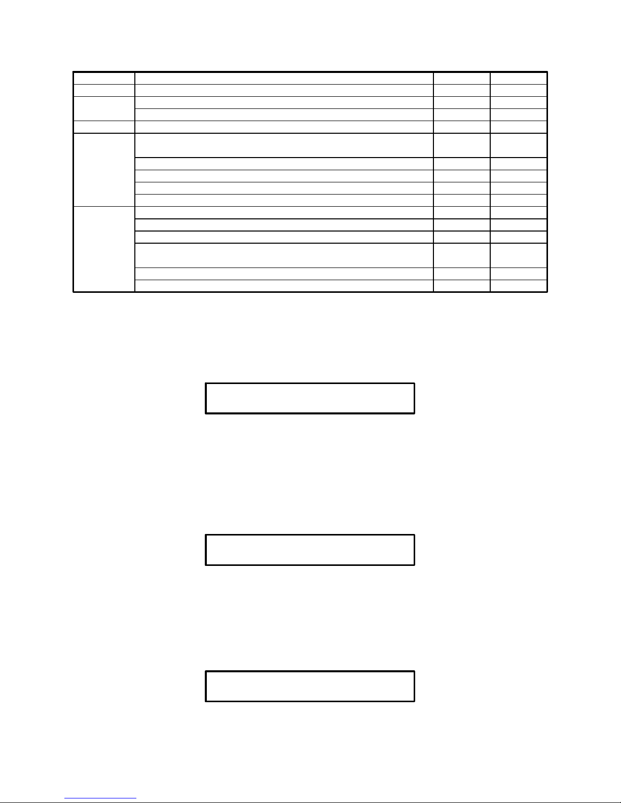
modification and will be switched into display mode. Table 2 presents user’s settings.
Columns of the table represent: fast flashing light, parameter name and available
minimum and maximum setting.
Page 12
12
Table 2. User settings list.
Light Parameter Min. Max.
Auger Fuel type. 1 4
Thermostat
Desired boiler temperature. 40°C 90°C
Boiler maximum power. 60% 100%
CH pump Central heating pump operation mode. WINTER SUMMER
HTW
pump
Domestic water desired temperature. 30°C 60°C
Domestic water heating priority. NO YES
Domestic water tank bacterial flora liquidation program. NO YES
Measured domestic water temperature.
Measured return water temperature.
Igniter
Current furnace brightness (FD-1).
Brightness when fuel ignition has occurred (FD-1). 0 255
Temperature of the burner (PT-1000, CT-1/2).
Burner temperature with fuel ignited (PT-1000, CT-1/2).
20°C
20°C
500°C
100°C
Burner work time.
Burner start up counter.
4.1. Fuel type selection.
RK-2006LP controller enables programming ignition settings for four different fuel
types. „Fuel type” parameter enables switching between particular settings. Fan,
auger and igniter operation are saved for the selected fuel type.
F U E L
T Y P E 1
CAUTION! Fuel type may be changed, if the controller is in STOP mode only.
4.2. Boiler temperature setting.
Desired boiler temperature - it is the temperature setting that will be obtained by
the controller, if room thermostat input contacts are closed.
D E S I R E D B O I L E R
T E M P E R A T U R E 5 0 c
4.3. Boiler operation maximum power.
Boiler operation maximum power - this parameter enables to limit boiler operation
max power. Power limitation is possible thanks to fuel reduction during operation at
maximum power.
M A X I M U M B O I L E R
P O W E R 1 0 0 %
Page 13

13
4.4. Domestic water circuit operation parameters.
These parameters specify how the controller ensures domestic water temperature.
In case of the system without domestic water circuit, it is not possible for the user to
view and change these parameters.
Domestic water desired temperature - parameter that specifies temperature of
water in domestic water tank that will be obtained by the controller.
D E S I R E D H . W A T E R
T E M P E R A T U R E 5 0 c
Domestic water heating priority - this parameter specifies operation of central
heating and domestic water pumps during hot water preheating. When priority is
selected during operation and hot water preheating, the controller engages domestic
water pump and switches off central heating pump. This operation results in quick
heating of water in the tank. During preparation of hot water without priority option,
central heating and domestic water pumps operation follow at the same time.
H O T W A T E R
P R I O R I T Y N O
Bacterial flora liquidation in domestic water tank - the controller enables manual
activation of program for bacterial flora liquidation in domestic water tank. When
„YES” is selected, it activates the process of heating the domestic water tank above
75°C. When the required temperature is obtained the controller switches off the
bacterial flora liquidation program automatically.
B A C T E R I A L F L O R A
L I Q U I D A T I O N N O
CAUTION! Bacterial flora liquidation option shall be switched on in the night or if
water intake does not follow from the domestic water tank, to protect the user
against burning.
Domestic water measured temperature – the controller enables to view the
temperature measured in domestic water tank.
M E A S U R E D H . W A T E R
T E M P E R A T U R E 4 8 c
4.5. Return water temperature.
If the heating circuit is equipped with the mixing pump and return temperature
sensor, this option enables view of the return water temperature. Otherwise, this
option in unavailable.
M E A S U R E D R E T U R N
T E M P E R A T U R E 3 2
c
Page 14

14
4.6. Flame optical detection parameters.
These parameters specify operation of burner flame optical detector. If the system is
fitted with flame temperature detector, parameters change and viewing is
unavailable.
The current furnace brightness determined by an optical detector - this
parameter displays the current flame brightness measured by the optical detector.
C U R R E N T F U R N A C E
B R I G H T N E S S 2 8
Brightness when fuel ignition has occurred - if the optical detector reading will be
equal or higher than this desired setting, the controller will switch off the igniter and
assume that ignition has occurred.
I G N I T I O N O F F A T
B R I G H T N E S S 1 4
4.7. Flame detection temperature parameters.
These parameters specify operation of the temperature detector of burner fuel
ignition. If the system is fitted with optical fire burner detector, parameters change
and viewing is unavailable.
Burner measured temperature - this parameter displays the current measured
burner temperature.
M E A S U R E D B U R N E R
T E M P E R A T U R E 6 6 c
Burner temperature with fuel ignited - if ignition temperature is equal or higher
than this desired setting, the controller will switch off the lighter and assume that
ignition was provided.
I G N I T I O N O F F A T
T E M P E R A T U R E 2 0 0 c
4.8. Information on burner work.
Parameters described below refer to counters that accumulate information on
operation of the burner since its first start. It is not possible to cancel counter
readings.
Burner work time.
Reading of this counter defines burner work time. The counter updating follows after
total working hour of the device at maximum or minimum power.
B U R N E R W O R K
T I M E 1 3
h
Page 15

15
Burner start up counter.
Reading of this counter defines start number of the ignition attempts.
B U R N E R S T A R T
C O U N T 8
5. Settings – service mode.
Holding OK button for 3 seconds enters the service mode where you can review and
change the parameters by pressing the selection buttons (8 and 11). After selection
of the given parameter you can enter into the change mode with OK button that is
indicated by the displayed symbol „→” on the left of the desired parameter. Pressing
OK button will confirm the change. If you press STOP button changes will not be
saved and old settings will be resumed. If the device is in change mode or
parameters reviewing for 60 seconds, the controller will automatically go back to the
display mode. Table 3 presents the list of all service settings. Columns of the table
represent: flashing light, parameter name and available minimum and maximum
setting.
Table 3. Service settings.
Light Parameter Min. Max.
No Language selection (See description).
Fan
Fan modulation during boiler start. NO YES
Min. fan speed during heating up. 1% 100%
Max. fan speed during heating up. 1% 100%
Ignition modulation start delay. 0s 250s
Fan speed during ignition. 1% 100%
Fan speed at max. power. 1% 100%
Fan speed at min. power. 1% 100%
Fan speed at extinction. 1% 100%
Fan speed during cleaning mode. 0% 100%
Fan scavenge (air purging). NO YES
Fan scavenge (air purging) blow time. 5s 60s
Fan scavenge (air purging) pause time. 1min 99min
Fan speed during scavenge. 1% 100%
Auger
Auger filling time. 1min 99min
Initial fuel feed. 0s 250s
Fuel feed cycle. 1s 250s
Fuel feed during ignition. 0% 100%
Fuel feed for max burner power. 1% 100%
Fuel feed for min. burner power. 1% 100%
Stoker work mode (See description).
Stoker work time. 1s 99s
Stoker pause time. 1s 99s
Stoker extra work time. 1s 99s
Stoker emptying time. 1s 99s
Auger ignition test. NO YES
Auger ignition temperature. 20°C 99°C
Igniter
Flame detector type (See description).
Correction FD-1. 0 99
Hysteresis loss of flame (optical sensor). 1
255
Page 16

16
Hysteresis loss of flame (temperature sensor). 1°C 250°C
Flame failure detection delay. 1s 500s
Fuel ignition time. 1min 15min
Kindle fire stabilize. NO YES
Kindle fire stabilize time. 1min 99min
Smooth kindle fire stabilize. NO YES
Ignition try count. 1 10
Furnace extinction time. 1min 30min
Furnace cleaning mode (See description).
Cleaning mechanism work time. 1s 900s
Cleaning mechanism retraction time. 1s 900s
Cleaning mechanism pause time. 1s 900s
Cleaning mechanism opening time. 1s 900s
Cleaning mechanism closing time. 1s 900s
Number shut downs before cleaning. 1 99
Minimum operating time without cleaning. 0h max-1h
Maximum working time without cleaning. min+1h 99h
CH pump
Central heating pump work mode (See description).
Central heating pump periodic work. NO YES
Central heating pump periodic work time. 1min 99min
HTW pump
Domestic water path (See description).
Domestic water heating hysteresis. 1°C 20°C
Boiler increase temperature during hot tap water heating. 2°C 20°C
Domestic pump work extension. NO YES
Domestic pump work extension time. 1min 10min
Stabilization time after heating up DHW. 1min 99min
Mixing pump engaging temperature. 30°C 60°C
Mixing pump work hysteresis. 1°C 9°C
Thermostat
Boiler minimum temperature. 30°C 69°C
Boiler maximum temperature. 70°C 90°C
Boiler upper hysteresis. 1°C 20°C
Boiler power switching hysteresis. 1°C 9°C
Boiler protection hysteresis. 1°C 5°C
Boiler overheating temperature. 90°C 99°C
Burner power modulation. NO YES
Modulation factor. 1 20
Thermostat working mode (see description).
Time constant of adaptation. 1min 99min
Delay in burner turn-off. 0min 99min
No
Resume service settings.
Outputs test.
Service mode end.
5.1. Language selection.
RK-2006LP controller interface offer the function of language selection. Number of
available languages depend on software version being used.
L A N G U A G E
E N G L I S H
Page 17

17
5.2. Fan operation parameters.
Fan modulation during boiler start - selection of „YES” setting means that fan
speed modulation will be provided during boiler start.
F A N M O D . D U R I N G
B O I L E R S T A R T Y E S
Min. fan speed during heating up - this parameter is available, if the function of fan
modulation during boiler start is selected. This parameter specifies power of the fan
during boiler start.
M I N . F A N S P E E D
H E A T I N G U P 1 %
Max. fan speed during heating up - this parameter is available, if the function of
fan modulation during boiler start is selected. This parameter specifies power of the
fan at end of boiler start.
M A X . F A N S P E E D
H E A T I N G U P 6 0 %
Ignition modulation start delay - this parameter is available, if the function of fan
modulation during boiler start is selected and it describes operation time of the fan
with speed according to the selected „Min. fan speed during boiler start” setting.
After time expire the controller will increase fan speed up to the selected „Max. fan
speed during boiler start” setting.
I G N I T I O N M O D U L .
S T A R T D E L A Y 5 0 s
Fan speed during ignition - this parameter describes power of the fan speed
during ignition. This parameter is unavailable if „Fan speed modulation during
ignition” was selected.
F A N S P E E D D U R I N G
I G N I T I O N 6 0 %
Fan speed at max. power - means the fan power when burner of the boiler works
with maximum power.
F A N S P E E D A T
M A X P O W E R 6 0 %
Page 18

18
Fan speed at min. power - means the fan power when burner of the boiler works
with minimum power.
F A N S P E E D A T
M I N P O W E R 3 0 %
Fan speed during extinction (shut down) - means fan power during burner
extinction (shut down).
F A N S P E E D D U R I N G
E X T I N C T I O N 1 0 0 %
Fan speed during cleaning mode – the parameter is available only when the
cleaning mechanism is in AUTO or COMBI mode. It defines the capacity at which
the fan is operating when cleaning the furnace.
F A N S P E E D D U R I N G
C L E A N I N G 1 0 0 %
Fan scavenge (air purging) - the controller offers the function of scavenge (air
purging), which simply includes periodical switching on of the fan during burner
operation for the purpose of removal of accumulated gases.
F A N
S C A V E N G E Y E S
Fan scavenge (air purging) blow time - this parameter specifies blow time. This
setting is unavailable if „Fan scavenge” (air purging) setting was not selected.
F A N S C A V E N G E
B L O W T I M E 5 s
Fan scavenge (air purging) pause time - this parameter specifies pause time
during scavenge. This setting is unavailable if „Fan scavenge” (air purging) setting
was not selected.
F A N S C A V E N G E
P A U S E T I M E 1 m i n
Fan speed during scavenge (air purging) - this parameter specifies fan power
during scavenge (air purging). This setting is unavailable if „Fan scavenge” (air
purging) setting was not selected.
F A N S P E E D D U R I N G
S C A V E N G E 1 0 0 %
Page 19

19
5.3. Fuel auger operation parameters.
Auger filling time - this parameter specifies time required for refilling the main
auger with fuel.
A U G E R F I L L I N G
T I M E 1 0 m i n
Initial fuel feed - this parameter specifies time, when fuel will be fed before igniter
start. Selection of „0s” setting will switch off initial fuel dose feeding. In this case
„Fuel dose during ignition” setting shall be programmed as the value over „0%”.
I N I T I A L F U E L
D O S E 1 0 s
Fuel feed cycle - auger operation cycle includes fuel feeding and feeding pause.
This parameter specifies the time of the whole cycle. The desired value specifies all
burner work modes which require fuel feeding (ignition, maximum and minimum
power).
F U E L F E E D
C Y C L E 1 5 s
Fuel feed during ignition - this parameter specifies fuel dose that is fed to the
burner during lighter operation. The programmed setting specifies feeding time in
percent in relation to the time of whole work cycle. Selection of „0s” setting will
switch fuel feeding during operation of the lighter. In this case „Initial Fuel Dose”
setting be shall be programmed as the value over „0s”.
F U E L D O S E D U R I N G
I G N I T I O N 2 0 %
Fuel feed for max. burner power - this parameter specifies fuel dose fed to the
burner during operation with maximum power. The programmed setting specifies
feeding time in percent in relation to the time of whole work cycle.
F U E L D O S E F O R
M A X P O W E R 5 0 %
Fuel feed for min. burner power - this parameter specifies fuel dose fed to the
burner during operation with minimum power. The programmed setting specifies
feeding time in percent in relation to the time of whole work cycle.
F U E L D O S E F O R
M I N P O W E R 2 0 %
Page 20

20
Stoker work mode - this parameter specifies work mode of the stoker:
„OFF” - the burner without the stoker.
„CYCL.” - stoker is switched on periodically, regardless of the auger. Work
and pause time of the stoker is determined with particular settings.
„AUTO” - operation mode when the stoke is switched on along with the
auger and is switched off with a delay defined with „Stoker extra work time” setting.
S T O K E R WO R K
M O D E A U T O
Stoker work time - this parameter specifies operation time of the stoker in whole
work cycle. This setting is unavailable if the stoker is switched off or in automatic
mode.
S T O K E R WO R K
T I M E 3 s
Stoker pause time - this parameter specifies pause time during stoker operation
when in work cycle. This setting is unavailable if the stoker is switched off or in
automatic mode.
S T O K E R P A U S E
T I M E 3 s
Stoker extra work time - this parameter is available only, when the stoker works in
automatic mode and it specifies stoker work time after auger switching off.
S T O K E R E X T R A
W O R K T I M E 2 0 s
Stoker emptying time – this parameter specifies time needed for removal of the
whole fuel from the stoker. Stoker emptying during extinguishing of feeder, feeding
initial fuel dose (portion), and during burner shut down. This setting is unavailable if
the stoker is switched off.
S T O K E R E M P T Y I N G
T I M E 4 0 s
Auger ignition test - this parameter provides functionalities of „X” emergency input.
If „NO” setting was selected then „X” input will be used for connection of e.g. auger
flap opening contact sensor or the contact informing on operation of auger motor
overload switch. If „YES” setting was selected then „X” input will be used for
connection of auger temperature sensor used for ignition detection.
Page 21

21
A U G E R I G N I T I O N
T E S T Y E S
CAUTION! In case emergency input is not used, „NO” parameter shall be selected
in „Auger ignition test” setting and contacts of „X” input shall be closed.
Auger ignition temperature - this parameter specifies auger temperature, when the
controller activates auger ignition alarm. This parameter is unavailable when „NO”
was selected in „Auger ignition test” setting.
A U G E R I G N I T I O N
T E M P E R A T U R E 8 0 c
5.4. Fuel ignition, extinction (shut down) and cleaning combustion chamber.
Flame detector - flame detection may follow with two methods: burner temperature
measurement or brightness measurement. In case when temperature sensor is
used, depending on its location, temperature measurement range may be from
several degrees to several hundred degrees. If measured temperatures do not
exceed 100°C it is recommended to use CT-1 or CT-2 sensor. In case of higher
temperatures, PT-1000 sensor shall be used. For flame brightness measurement,
FD-1 optical detector shall be used.
F L A M E
D E T E C T O R F D – 1
Correction of the photodetector indications – the parameter is available only
when an optical flame detector (FD-1) has been selected. It determines the quantity
of light „seen” by the sensor after the burner has been extinguished. The value of
correction is deducted from the measured quantity of light during the flame detection
stage. The correction enables the user to calibrate the FD-1 sensor so that the result
of illuminance measurement while the burner is extinguished could equal „0”.
F D – 1
C O R R E C T I O N 0
Hysteresis loss of flame - depending on the type of flame detector, this parameter
specifies how many degrees or units in relation to the threshold set by the user must
cut off the lighter or the brightness of the flame temperature to the controller began
to flame failure detection procedure.
F L A M E V A N I S H
H Y S T E R E S I S 1 0
WARNING! If the hysteresis is larger than the threshold of igniter shut down, flame
failure detection procedure is started when the temperature drops or the brightness
of the flame to the value of „0”.
Page 22

22
Flame failure detection delay - this parameter specifies how long after the launch
procedures for the detection of flame failure or brightness temperature must remain
below the hysteresis for the regulator to decide that the furnace was extinguished.
F L A M E V A N I S H
D E L A Y 6 0 s
Fuel ignition time - after igniter and fan are switched on, the controller tests
temperature increase or brightness in the selected location of the burner. If flame is
not detected within the time programmed in this parameter, the controller will repeat
ignition cycle.
F U E L I G N I T I O N
T I M E 3 m i n
Ignition try count - this parameter specifies how many times ignition may fail until
the controller activates „Out of fuel alarm” and switches into STOP mode. The alarm
is indicated with adequate message displayed on the display. To start the controller
first refill the fuel, then cancel by pressing STOP button and start setting mode by
pressing START button.
I G N I T I O N T R Y
C O U N T 2
Kindle fire stabilize – the parameter determines if the mode of kindle fire stabilize is
switched on after the fuel has been ignited.
K I N D L E F I R E
S T A B I L I Z E Y E S
Kindle fire stabilize time – the parameter defines the maximum working time while
the regulator is in the mode of stabilizing the ignition. The parameter is not available
if the „Kindle fire stabilize” parameter has been set to „NO”.
K I N D L E F I R E
S T A B . T I M E 5 m i n
Smooth kindle fire stabilize – set the parameter to the “YES” value to allow the
regulator to increase the amount of fuel gradually while it is in the „Kindle fire
stabilize” mode. The parameter is not available if the „Kindle fire stabilize” parameter
has been set to „NO”.
S M O O T H K I N D L E
F I R E S T A B I L . Y E S
Page 23

23
Furnace extinction (shut down) time - if the controller switches to extinction (shut
down) mode, the induction fan is activated according to power selected in „Fan
speed at extinction (shut down)” setting. The parameter defines the duration of
extinction. This function ensures combustion of all fuel remains and burner cool
down.
F U R N A C E E X T I N C .
T I M E 5 m i n
Furnace cleaning mode - the parameter defines the way the cleaning mechanism
works.
„NONE" - means the burner is not equipped with a cleaning mechanism. In
such case, the DATA output works as an external alarm signalling device.
„CYCLE" - means the cleaning procedure is activated after the flame has
occurred and is repeated in cycles until the burner is extinguished (end of the
POSTCOMBUSTION mode). The cleaning depends on activating the mechanism for
the period set in the „Cleaning mechanism work time" parameter. Once the cleaning
mechanism has been turned off, the time set in the „Cleaning mechanism retraction
time" and „Cleaning mechanism pause time" parameters is counted down.
„ROTO” - the cleaning mechanism operation in the ROTO mode is similar to its
work in the CYCLE mode. The difference is the output controlling the cleaning
mechanism is activated for the whole period of the EXTINCTION mode.
„AUTO" - means the cleaning procedure is automatic and is activated when the
determined number of shutdowns or long burner working time occurs. The automatic
cleaning depends on the furnace extinction, starting the cleaning mechanism for the
period set in the „Cleaning mechanism opening time" parameter and activating the
fan with capacity defined in the „Fan speed when cleaning” parameter. When the
mechanism output and the fan are turned off, the time set in the „Cleaning
mechanism closing time" parameter will be counted down and the controller
standard work will be resumed.
„COMBI” - the mode is a combination of the „CYCLE” and „AUTO” modes. The
mechanism starts its operation after the KINDLE FIRE STABILIZE has finished – its
work is turned on and off in cycles whose duration is defined in the „Mechanism
working time” parameter. When the cleaning mechanism is turned off, the time set in
the „Mechanism retraction time” and „Mechanism pause time” parameters is counted
down. When the cleaning mechanism is in the EXTINCTION mode, its output is
turned off. Once the determined number of SHUTDOWNS occur or the burner
operates long enough, the automatic cleaning will be activated (furnace extinction,
activation of the cleaning mechanism for the time set in the „Mechanism opening
time” parameter and starting the fan with the capacity determined in the „Fan speed
during cleaning” parameter). When the output of the mechanism is turned off, the fan
is not active, the time set in the „Mechanism closing time” parameter is counted
down and then the regular work is resumed.
Page 24

24
H E A R T H
C L E A N I N G A U T O
Cleaning mechanism work time - the parameter is available only when the
cleaning mechanism operates in the CYCLE, ROTO or COMBI mode. It defines the
duration the cleaning mechanism is activated when the burner is turned on.
M E C H A N I S M W O R K
T I M E 1 2 0 s
Cleaning mechanism retraction time - the parameter is available only when the
cleaning mechanism operates in the CYCLE, ROTO or COMBI mode. It defines the
time required for the mechanism retraction to the resting position after the control
output has been turned off.
M E C H A N I S M R E T U R N
T I M E 1 2 0 s
Cleaning mechanism pause time - the parameter is available only when the
cleaning mechanism operates in the CYCLE, ROTO or COMBI mode. It defines the
period between the mechanism successive turn-ons.
M E C H A N I S M P A U S E
T I M E 1 2 0 s
Cleaning mechanism opening time – the parameter is available only when the
cleaning mechanism operates in the AUTO or COMBI modes. It defines the time
needed to fully open the mechanism when the automatic cleaning is on.
M E C H A N I S M O P E N
T I M E 1 2 0 s
Cleaning mechanism closing time – the parameter is available only when the
cleaning mechanism operates in the AUTO or COMBI modes. It defines the time
required for the mechanism retraction to the resting position after it fully opened
while the automatic cleaning.
M E C H A N I S M C L O S E
T I M E 1 2 0 s
The number of shutdowns before cleaning - the parameter is available only when
the cleaning mechanism operates in the AUTO or COMBI modes. It determines the
moment following a shutdown after which the cleaning procedure will be activated.
E X T I N C T I O N C O U N T
B E F O R E C L E A N
5
Page 25

25
Minimum operating time without cleaning - the parameter is available only when
the cleaning mechanism operates in the AUTO or COMBI mode. It specifies the
minimum number of hours the burner must operate so that the cleaning could be
activated. If the minimum operation time is not reached, the cleaning will not be
started even if the required number of shutdowns has occurred. To turn off the
„Minimum operating time without cleaning' option, set the parameter to „0h'.
M I N WO R K W I T H O U T
C L E A N I N G 2 h
Maximum operating time without cleaning - the parameter is available only when
the cleaning mechanism operates in the AUTO or COMBI mode. It specifies the
maximum number of hours the burner can work without cleaning. If the maximum
time is reached, the cleaning will be started even if the required number of
shutdowns has not occurred.
M A X W O R K W I T H O U T
C L E A N I N G 1 2 h
5.5. Central heating pump work parameters.
Central heating pump switching on parameters - this parameter specifies the
method of central heating pump switching on. Selection of „THERMOSTAT” setting
means that central heating pump will be switched on only if room thermostat
contacts are closed and in case of emergency (e.g. boiler overheating). Selection of
„AUTO” setting means that central heating pump operation will follow regardless of
room thermostat.
C H P U M P W O R K
M O D E A U T O
Central heating (CH) pump periodic switching on - this parameter enables
periodic operation of central heating pump and water transfer in the heating circuit.
The pump is activated periodically every 30 seconds according to selected time in
„CH pump periodic work” setting. This function in available, if „THERMOSTAT” was
selected in CH pump work mode
C H P U M P P E R I O D I C
W O R K Y E S
CH pump periodic work time - this parameter is available, if CH pump works in
„THERMOSTAT” mode and the function of CH pump periodic work is active. The
programmed setting will specify the time lapse between CH pump work, in case of
opened contacts of the room thermostat.
C H P U M P P E R I O D I C
W O R K T I M E 2 m i
n
Page 26

26
5.6. Setting domestic water pump parameters.
The controller offers an additional function for heating of domestic water. Not every
heating system is provided with domestic water tank and charge pump, this circuit
may be switched off or used for control of the pump that mixes the return water in
the boiler.
Domestic water path - if „NONE” is selected the domestic water pump is off. In this
case temperature sensor input and pump control output may remain disconnected.
Selection of „EXISTS” setting provides for interlock release of all parameters and
functions related to domestic water path handling. Election of „MIXING PUMP”
setting will switch domestic water in the circuit purposed for control of the mixing
pump. In this case return water temperature sensor shall be connected instead of
domestic water sensor, and the mixing pump instead of charge pump of domestic
water tank.
H O T W A T E R P A T H
E X I S T S
Domestic water heating hysteresis - this parameter indicates water temperature
drop in the tank in relation to the programmed setting (so that charge pump was
switched on). This setting is available, if domestic water path „EXISTS” setting was
selected.
H W H E A T I N G
H Y S T E R E S I S 5 c
Increase temperature during domestic water heating - Closing thermostat
contacts means that boiler operation will follow according to the temperature
programmed with the thermostat knob. If domestic water tank heating is necessary,
the desired boiler temperature is higher in relation to the desired domestic water by
the selected value in this setting. In case of simultaneous operation of the room
thermostat and domestic water tank heating, the controller operation will follow to
maintain the higher boiler temperature. This setting is available, if domestic water
path „EXISTS” setting was selected.
I N C R E A S E T E M P . O N
H W H E A T I N G 5 c
Domestic water pump work extension - quick switching off of the pump refilling
domestic water tank may result in excessive rise of boiler temperature. This
parameter enables switching on of domestic water pump extension. This setting is
available, if domestic water path „EXISTS” setting was selected.
H W P U M P W O R K
E X T E N S I O N Y E S
Page 27

27
Domestic water pump extension time - this parameter specifies the time lapse
when domestic water is switched off since the moment when the programmed
temperature of domestic water tank was obtained. This setting is available, if
domestic water path „EXISTS” setting was selected and pump extension was
selected.
H W P U M P E X T E N D
T I M E 2 m i n
Sabilization time after heating up DHW – while preparing the domestic hot water
with priority on, the whole boiler capacity is used to heat up DHW. The boiler
programmed temperature when it works for the DHW is often higher than the
required temperature in the CH circulation. Additionally, when the CH pump is turned
off while it works with DHW priority, the cooldown of the heated rooms and activation
of the household thermostat input may occur. In such case, when the work with
DHW priority has finished, the temperature of the boiler water might be higher than
the temperature required for heating up the rooms – the fact may be the reason for
the burner extinction because the boiler upper hysteresis would be exceeded. The
parameter defines the time required to stabilize the circulation after heating the DHW
with priority on has finished. During the stabilizing, the upper hysteresis check is
stopped and the adaptive algorithm of the household thermostat is suspended. The
parameter is available only when the DHW duct is turned on.
S T A B . T I M E A F T E R
H W H E A T I N G 5 m i n
CAUTION! The option will not be active if preparing the DHW is carried out without
priority or the controller is in the SUMMER mode.
Mixing pump engaging temperature - this parameter specifies required return
water temperature so that the mixing pump engagement follows the controller. This
parameter is available if domestic water path „MIXING PUMP” setting was selected.
M I X I N G P U M P
E N G A G E T E M P 5 0 c
Mixing pump work hysteresis - this parameter specifies required return water
temperature increase in relation to the mixing pump engagement temperature so
that the controller switches off the mixing pump. This parameter is available if
domestic water path „MIXING PUMP” setting was selected.
M I X I N G P U M P W O R K
H Y S T E R E S I S 5 c
Page 28

28
5.7. Boiler work parameters.
Minimum boiler temperature - this parameter specifies boiler temperature when
the controller shall switch off central heating and domestic water pumps. It is the
lowest temperature setting of the boiler that can be programmed with thermostat’s
knob.
M I N I M U M B O I L E R
T E M P E R A T U R E 4 0 c
Maximum boiler temperature - this parameter specifies boiler max. programmed
temperature setting which can be programmed with thermostat’s knob. It is also
boiler temperature when central heating pump is engaged to provide protection for
the boiler against overheating.
M A X I M U M B O I L E R
T E M P E R A T U R E 9 0 c
Boiler upper hysteresis - if the controller works in burner minimum power mode,
and boiler temperature increase follows by this programmed setting, the controller
will start burner extinction(shut down).
B O I L E R U P P E R
H Y S T E R E S I S 5 c
Burner power switching hysteresis - when the programmed boiler water
temperature is obtained the controller is switched to minimum power work mode.
This parameter specifies required water temperature drop so that maximum power
work mode was activated. After switching to maximum power the fuel and air feeding
dose is determined according to burner power modulation.
B U R N E R P O W E R S W .
H Y S T E R E S I S 1 c
Boiler protection hysteresis - the controller provides for boiler minimum and
maximum temperature by providing control over operation of central heating and
domestic water pumps. This parameter specifies hysteresis parameter of boiler limit
temperatures switching off.
B O I L E R P R O T E C T .
H Y S T E R E S I S 2 c
Boiler overheating temperature - this parameter specifies boiler water temperature
when the controller switches off control and activates boiler overheating alarm.
B O I L E R O V E R H E A T
T E M P E R A T U R E 9 8
c
Page 29

29
Burner power modulation - when modulation is switched on it will results in
gradual reduction of fan speed and fuel dose to obtain boiler water temperature
corresponding to the programmed setting.
B U R N E R P O W E R
M O D U L A T I O N Y E S
Burner power modulation factor - this parameter specifies degree setting when
the controller will reduce burner power before boiler water temperature is obtained
according to the programmed setting. Burner power is reduced by gradual reduction
of fed fuel dose and fan speed reduction. This parameter is unavailable, if burner
modulation power is off.
M O D U L A T I O N
F A C T O R 5
5.8. Room thermostat.
RK-2006LP controller has been equipped with the input enabling connection of any
room thermostat provided with contact output. Closing the thermostat contacts is
signalized with blinking its lamp. When the contacts are opened, the lamp will be off.
CAUTION! The room thermostat input is active during work in the WINTER mode
only. The indicator signalizing the status of the input is independent of the entered
mode.
Room thermostat working mode - the parameter determines the influence of the
room thermostat input on the controller operation:
„NORMAL” - in the mode, once the thermostat contacts are closed, the burner
is ignited, and the boiler is going to maintain the temperature set with the boiler
thermostat knob. When the desired temperature is reached and the thermostat
contacts are opened, the burner extinction occurs and the controller enters the
STANDBY mode.
„ADAPTIVE” - in the mode, the changes in the thermostat input status are
analysed - on their basis the boiler programmed temperature is defined
automatically.
T H E R M O S T A T W O R K
M O D E N O R M A L
CAUTION! When the room thermostat is unused, its input should remain closed and
the thermostat working mode should be set to „NORMAL” In such case, the
temperature programmed with the boiler thermostat knob will be maintained
continuously.
Page 30

30
Time constant of adaptation – the parameter is available when the thermostat is in
the mode of adaptation. It defines the rate of „searching' the appropriate boiler
programmed temperature by the algorithm of adaptation. The value of parameter
should be selected experimentally depending on the properties of the heated object.
When frequent room overheating occurs during the work of the algorithm of
adaptation and frequent changes in the outside conditions – the value of the time
constant should be decreased.
A D A P T I V E T I M E
C O N S T A N T 1 0 m i n
Delay in burner switch off – the parameter determines the working time of the
burner at the minimum power and when the thermostat contacts are opened. Once
the programmed time is finished and the thermostat contacts are not closed again,
the burner will be extinguished and the controller will enter the STANDBY mode.
When the parameter is set to the „0min” value, the burner will be extinguished
immediately after the thermostat contacts have been opened.
B U R N E R S W I T C H
O F F D E L A Y 0 m i n
CAUTION! The burner may be turned off after the thermostat contacts have been
opened with a delay different from the programmed one if the DHW circulation is
also controlled.
5.9. Service settings.
If „YES” selection followed and was confirmed with OK button when this option is
displayed will result in cancelling of all parameters and restoration of default
parameters programmed before by the fitter or technician.
S E R V I C E
S E T T I N G S N O
CAUTION! Activation of this function will result in restoration of service parameters
for current fuel type only.
5.10. Output testing.
It is possible to test particular preset functions. This is available, only, if the controller
is in STOP mode before switching to service mode. To select outputs testing option
use the knob (12) choosing particular outputs which are indicated by flashing of the
proper light and output name displayed. By pressing OK button you can turn on the
selected output temporarily. To finish output testing press STOP button.
T E S T I N G O U T P U T S
F A N 0
Page 31

31
5.11. Service mode exit.
By choosing this option and confirmation with OK button you can exit service mode.
The controller also exits the service mode, if no button is pressed after 60 seconds.
– – E X I T – –
6. DATA emergency output - audible alarm or cleaning mechanism.
The regulator has output DATA allows you to connect via the UM-1 module siren
alarm or additional cleaning mechanism. If you exit this mode, the siren is in alarm, it
is activated in the event of: sensor failure of the boiler, burner sensor, the sensor or
mixing pump hot water, boiler overheating or lack of fuel.
7. Controller disassembly.
If controller disassembly is necessary follow the following procedure:
- Disconnect the boiler and controller from power supply,
- Remove the controller from the boiler,
- Disconnect terminals and wires from the controller.
8. Technical Data.
Power Supply 230V ± 10%, 50Hz
Power consumption (without fan and pump) < 4VA
Burner temperature measurement range (KTY 81-210) -9–109°C ±1°C
Temperature measurement range (KTY 81-210) -9–109°C ±1°C
Burner temperature measurement range (PT-1000) -30–500°C ±3°C
Boiler temperature adjustment range 30–90°C ±1°C
Boiler programmed overheating protection 90–99°C ±1°C
Boiler equipment overheating protection >95°C ±1°C
Total outputs rating max 4A/230V
Dimensions (H x W x D) 96x144x94
Page 32

32
Figure 2. RK-2006LP Controller connection diagram.
Page 33

33
9. Notes.
Light Parameter
Settings.
1 2 3 4
Thermostat Boiler max. power.
HTW pump
Domestic water desired temperature.
Domestic water heating priority.
Igniter
Brightness when fuel ignition has occurred
(FD-1).
Burner temperature with fuel ignited (PT-1000,
CT-1/2).
Page 34

34
Light Parameter
Settings
1 2 3 4
Fan
Fan modulation during boiler start.
Min. fan speed during heating up.
Max. fan speed during heating up.
Ignition modulation start delay.
Fan speed during ignition.
Fan speed at max. power.
Fan speed at min. power.
Fan speed at extinction.
Fan speed during cleaning mode.
Fan scavenge(air purging).
Fan scavenge (air purging) blow time.
Fan scavenge(air purging) pause time.
Fan speed during scavenge.
Auger
Auger filling time.
Initial fuel feed.
Fuel feed cycle.
Fuel feed during ignition.
Fuel feed for max burner power.
Fuel feed for min. burner power.
Stoker work mode.
Stoker work time.
Stoker pause time.
Stoker extra work time.
Stoker emptying time.
Auger ignition test.
Auger ignition temperature.
Igniter
Flame detector type.
Correction FD-1.
Hysteresis loss of flame (optical sensor).
Hysteresis loss of flame (temperature sensor).
Flame failure detection delay.
Fuel ignition time.
Ignition try count.
Kindle fire stabilize.
Page 35

35
Light Parameter
Settings
1 2 3 4
Igniter
Kindle fire stabilize time.
Smooth kindle fire stabilize.
Furnace extinction time.
Furnace cleaning mode.
Cleaning mechanism work time.
Cleaning mechanism retraction time.
Cleaning mechanism pause time.
Cleaning mechanism opening time.
Cleaning mechanism closing time.
Number shut downs before cleaning.
Minimum operating time without cleaning.
Maximum working time without cleaning.
CH pump
Central heating pump work mode.
Central heating pump periodic work.
Central heating pump periodic work time.
HTW pump
Domestic water path.
Domestic water heating hysteresis.
Boiler increase temperature during hot tap water heating.
Domestic pump work extension.
Domestic pump work extension time.
Stabilization time after heating up DHW.
Mixing pump engaging temperature.
Mixing pump work hysteresis.
Thermostat
Boiler minimum temperature.
Boiler maximum temperature.
Boiler upper hysteresis.
Boiler power switching hysteresis.
Boiler protection hysteresis.
Boiler overheating temperature.
Burner power modulation.
Modulation factor.
Thermostat working mode (see description).
Time constant of adaptation.
Delay in burner turn-off.
Page 36

36
Page 37

37
Page 38

38
Page 39

DECLARATION OF CONFORMITY
Manufacturer: Przedsiębiorstwo Wielobranżowe KEY
11-200 Bartoszyce, ul. Bohaterów Warszawy 67
hereby declares that the product:
RK-2006 Controller
is in conformity with provisions of the following directives:
73/23/EWG i 93/68/EWG (LVD 73/23/EEC + 93/68/EEC),
as superseded by Directive 2006/95/WE (EC Directive 2006/95/EEC);
89/336/EWG (Elektromagnetic Compatibility Directive 89/336/EEC),
as amended by Directive 93/68/EWG (EMC Directive 93/68/EEC)
on basis of compliance with the following harmonised directives:
PN-EN 55022:2006(U)
PN-EN 61000-4-2:1999+A2:2003
PN-EN 61000-4-3:2006(U)
PN-EN 61000-4-6:1999+A1:2003+IS1:2006
PN-EN 61000-4-4:2005(U)
PN-EN 61000-4-5:2006(U)
PN-EN 61000-4-11:2005(U)
PN-EN 60730-1:2002+A1:2006(U)A12:2004+A13:2005
PN-EN 60730-1:2005+A14:2006
PN-EN 60730-2-9:2006
PN-EN 61000-3-2:2006(U)
PN-EN 61000-3-3:1997+A1:2005+A2:2006+IS1:2006
Information on disposal
This appliance is marked according to the European Directive 2002/96/EC on Waste
Electrical and Electronic Equipment (WEEE).
The symbol on the product, or the documents accompanying the product, indicates that
his appliance may not be treated as household waste.
The appliance shall be handed over to the applicable collection point for used up
electrical and electronic equipment for recycling purpose.
Ultimate disposal of the appliance shall follow according to applicable local regulations
on waste utilization. For more information about disposal, utilization and recycling
please contact your local authorities, household waste disposal service or the shop
where you purchased the product.
Page 40

Manufacturer: Przedsiębiorstwo Wielobranżowe KEY
11-200 Bartoszyce, ul. Bohaterów Warszawy 67
tel. (89) 763 50 50, fax. (89) 763 50 51
www.pwkey.pl e-mail:pwkey@onet.pl
 Loading...