

KEY RK-2001W4 Operation Manual
OPERATION MANUAL
RK-2001W4
SOLID FUEL FIRED
BOILER TEMPERATURE CONTROLLER
Wersja E128

Table of Contents.
Introduction ................................................................................................... 3
Operation ...................................................................................................... 3
Method of determining the set temperature of the boiler .............................. 4
Working in combination with exhaust gas sensor ......................................... 5
Working in combination with a room thermostat .......................................... 6
Alarms .......................................................................................................... 6
Setting up the user parameters. ..................................................................... 7
The desired boiler temperature [C 45] ............................................................. 7
Central heating pump work [co C] – WINTER/SUMMER ............................... 7
Total bacteria control in the hot water tank [cu u] ........................................... 8
The temperature measured by the additional sensor [u50 °] .......................... 8
The temperature measured emissions [150 °] ................................................ 8
Parameter setting – the service mode ............................................................ 8
Table 2. Service parameters list ...................................................................... 9
Pressure fan work parameters ........................................................................ 10
Central heating pump parameters .................................................................. 11
Settings of the sensor operation mode and additional pump .......................... 11
Setting the operating temperature range of the boiler .................................... 12
Boiler overheating protection .......................................................................... 13
No fuel ............................................................................................................. 13
Multifpurpose output ....................................................................................... 13
Setting the exhaust gas temperature control parameters ............................... 14
Testing of device's outputs .............................................................................. 14
Factory defaults .............................................................................................. 14
Exiting service mode ....................................................................................... 15
Device removal ............................................................................................... 15
Specifications .................................................................................................. 15
Connection diagram of the RK-2001W4 ......................................................... 16
Schemes of connecting additional devices ..................................................... 16

3
1. Application.
Controller RK-2001W4 is a device designed for temperature control in solid fuel fired
boilers equipped with:
- blower,
- central heating pump,
- domestic hot water pump, mixing pump or a pump charging the accumulative tank
(optional),
- household thermostat or exhaust gases temperature sensor (optional),
- signalling device or an additional boiler (optional).
2. Connection.
Before connecting the controller to the power supply, check if: power cords of the
controller, the blower and the central heating circulation pump are properly plugged
in the appropriate slots at the back of the device. The boiler water temperature and
the exhaust gases temperature sensors should be installed in a measurement
openings of the boiler. The schematics of connecting the regulator is shown in
picture 2.
CAUTION! Before plugging in the controller first check if the wiring system is
properly grounded and if the screw terminals of the output connector are tightened.
CAUTION! The total power of the devices connected to the controller must not
exceed 700W.
The unused outputs may remain disconnected.
3. Operation.
Turning on the controller is signalized by a brief switching on all the light indicators
on the display to enable to check their status. After the regulator has been
connected to the power supply, it returns to its most recent mode (before turning it
off or power failure).
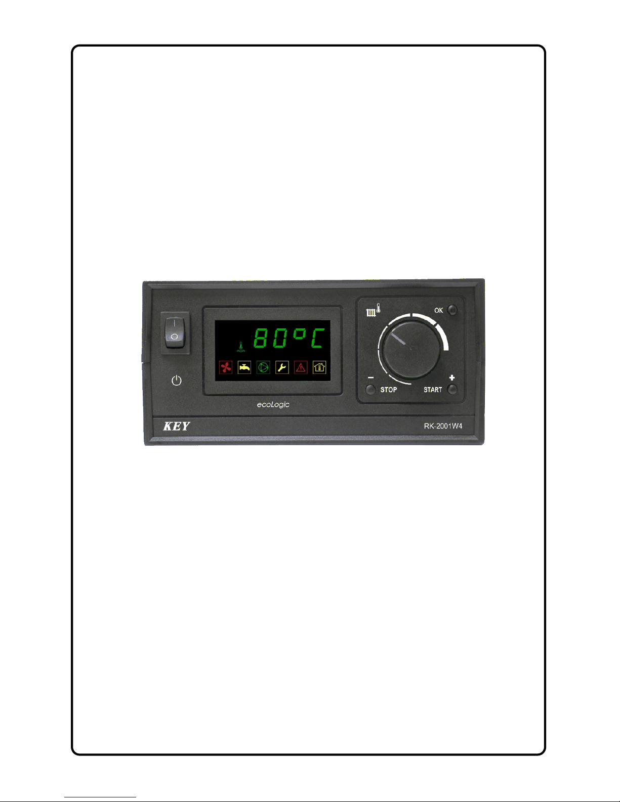
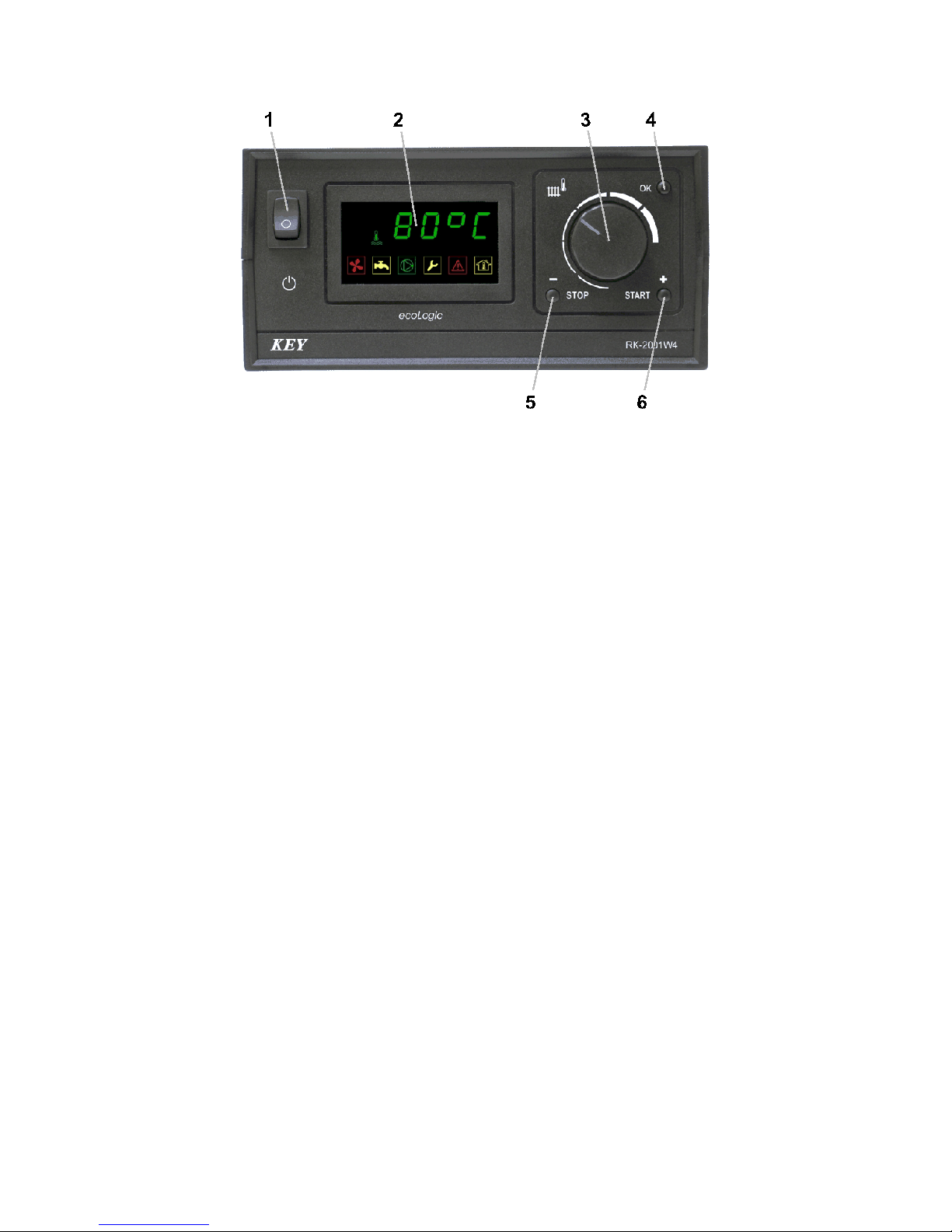
The front panel of the controller (picture 1) includes:
1 – power switch,
2 – boiler temperature and parameters indicator,
3 – boiler thermostat knob,
4 – Ok button used for programming activation and parameters confirmation,
5 – STOP button also used for parameters selection and alarm cancellation,
6 – START button also used for parameters selection.
4
Picture 1. Front panel of the RK-2001W4 controller.
The basic operation of the regulator depends on setting the desired temperature with
the thermostat knob. The remaining functions are carried out according to the
programmed parameters of the service mode. The change of thermostat parameters
is shown on the display for a few seconds, e.g. [C 65] and defines the value of the
boiler water temperature the regulator is going to reach.
ressing the START (6) button activates both the blower and the possibility of its
control. The STOP (5) button allows the user to stop the work of the blower, e.g. in
order to refuel the boiler. If the regulator is out of the user’s mode, the temperature
of the boiler water is shown on the display and the last symbol indicates the working
mode status:
[50°-] - stands for the STOP mode
[50°C] is the WORK mode
[50°c] indicates maintaining the heating while in the WORK mode
[50°U] means heating the domestic hot water in SUMMER mode
[50°u] is maintaining the heating while in SUMMER mode
.[70°d] indicates the bacteria eradication mode – heating the domestic
hot water up to 75°C
3.1. The method of determining the desired temperature of boiler water.
The temperature maintained in the boiler (the programmed one) depends on the
working mode of the household thermostat input (the exhaust gases sensor) as well
as on the additional pump working mode. Table 1 contains the list of all parameters
values possible to set.

5
If the circulation system is equipped with the accumulative tank, the desired boiler
water temperature equals the value set with the thermostat knob (3).
If the heating system is equipped with the domestic hot water tank, the higher of two
component temperatures is accepted as the desired boiler water temperature –
either the temperature needed by the central heating circulation or the boiler water
temperature necessary to heat up the domestic hot water tank.
In all other cases (no additional pump and when the mixing pump is installed) the
desired boiler water temperature is the same as the temperature needed by the
central heating circulation.
The temperature necessary to heat up the tank is taken into account when the
domestic water temperature is too low only and it equals the total of the programmed
hot water temperature [u 50] and the value of its increase [uP 5].
The temperature needed by the central heating circulation is determined on the
basis of the value set with the thermostat knob (3) and the household thermostat
input status. If the exhaust gases sensor is connected, then the central heating
temperature equals the value set with the knob. If the household thermostat is
connected and its contacts are opened, the central heating temperature is the same
as the minimum boiler temperature [L 45], and if its contacts are opened, the central
heating temperature equals the value set with the knob.
Table 1. Methods of establishing the desired temperature of boiler water.
Thermostat
input
Additional pump working mode
None
[ur 0]
Domestic hot water
[ur 1] lub [ur 2] Mixing pump
[ur 3]
Accumulator
[ur 4]
Exhaust gases
sensor
Set with knob
Of which higher:
– Set with knob
– Domestic water
heating temperature
Set with knob Set with knob
Thermostat
contacts
opened
Minimum
Domestic water
heating temperature Minimum Set with knob
Thermostat
contacts closed
Set with knob
Of which higher:
– Set with knob
Domestic water
heating temperature
Setpoint knob Set with knob
3.2. System with the exhaust gases sensor operation.
If the heating system has been equipped with the exhaust gases temperature sensor
and the temperature of the boiler water approaches the desired value, the regulator
will switch into the mode of stabilizing the boiler water temperature.

6
3.3. System with the household thermostat operation.
If the heating system is equipped with the household thermostat, the desired
temperature of the boiler water depends on the status of its contacts (3.1.). As an
addition the central heating pump work may, depending on the service settings, be
influenced by the household thermostat.
4. Alarms.
The correctness of the inside circuits and the temperature sensors work is tested
continuously. When a failure is detected, the information of the errors that has
appeared is displayed and the adequate action is undertaken.
The [FUEL] caption when displayed indicates fuel demand alarm. After the boiler has
been refuelled, the alarm can be cancelled with the STOP button.
The [Hot] caption is displayed alternately with the exhaust gases temperature e.g.
[°410] means the temperature of 400°C has been exceeded by the exhaust gases. In
such case the blower is turned off by the regulator (it is turned on during draught cycle
only). The regular work is resumed after the temperature of the exhaust gases has
decreased below 250°C.
The [E 1] error indicates that a failure in the boiler sensor circuit has occurred. The
error will induce the blower to turn off and the central heating pump to turn on. After
the reason for the alarm has been removed, it can be cancelled with the STOP button.
The [E 2] error indicates that the boiler overheating has occurred. The error will
induce the blower to turn off and the central heating pump to turn on. The alarm can
be cancelled with the STOP button after the boiler water temperature has decreased.
The [E 8] indicates that a failure of the additional sensor circuit has occurred. If the
additional output operates in the domestic hot water pump working mode, then the
topping up the hot water tank is ceased. When the output works as a mixing pump, the
protection of the return temperature is turned off. If the additional pump is intended to
charge the accumulative tank, then it is turned on permanently. It is not necessary to
cancel the alarm manually (it is cancelled automatically after the reason for failure has
been removed).
The [E128] indicates that a failure of the exhaust gases temperature sensor has
occurred. In case of the alarm, the regulator operation is continued in the stabilizing
the boiler temperature mode. The alarm does not need cancelling manually (it is
cancelled automatically after the reason for failure has been removed).
When several errors occur at the same time, the total of their codes is shown on the
display, e.g. the [E 3] caption indicates both failure of the boiler temperature sensor
and boiler overheating have occurred.
 Loading...