

Page 1
OPERATION MANUAL
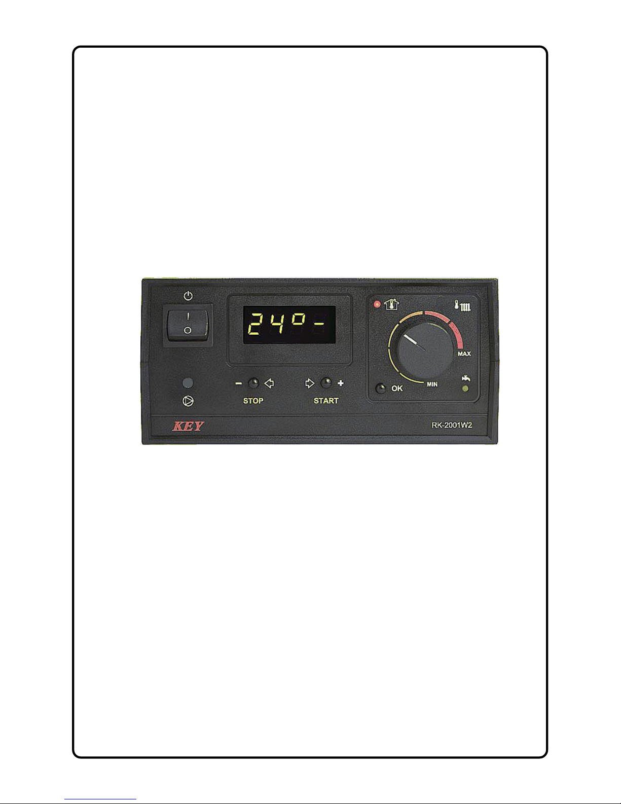
RK-2001W2
SOLID FUEL FIRED
BOILER TEMPERATURE CONTROLLER
Version C112
Page 2

Page 3

3
1. Application.
RK-2001W2 controller is a controller designed for temperature control of solid fuel fired
boilers. The temperature of the boiler is kept on level set by the user by controlling the
speed of the blow-in fan. The controller constantly monitors the temperature of water
in the boiler, displays it on the display and controlls the central heating pump. To
enable more precise temperature control of heated rooms the controller has been
equipped with an input for room thermostat connection. The controller is able to
control the pump loading tap water tank. The controller is equipped with extra
programmable multi-functional output, which allows connecting mixing valve, alarm
signal, extra boiler (gas or oil-fueled), emergency cooling system or other devices
turned on simultaneously with blow-in fan.
2. Connection.
Before turning on the controller by master switch, connect controller, fan and the
central heating pump power leads to appropriate sockets in the rear of the controller.
The temperature sensor should be placed in a measurement hole in the boiler.
Pictures 2 and 3. shows diagram of electrical connection of the controller.
CAUTION! Before plugging in the controller check if the wiring system is properly
grounded and if the terminal screws of the output connector are properly screwed.
CAUTION! Total power of the fan, central heating pump and hot water pump, which
are connected to the controller, musn't exceed 690W.
CAUTION! In case of connecting additional devices to the controller via UM-1 module,
these devices must be protected by appropriate fuses.
Outputs of the controller that are not used may remain unconnected.
3. Operation.
After turning the controller on all the elements of the display are lit for a while to check
if they are working properly. The controller, when power appears, returns to its last
state before turning off or power loss.
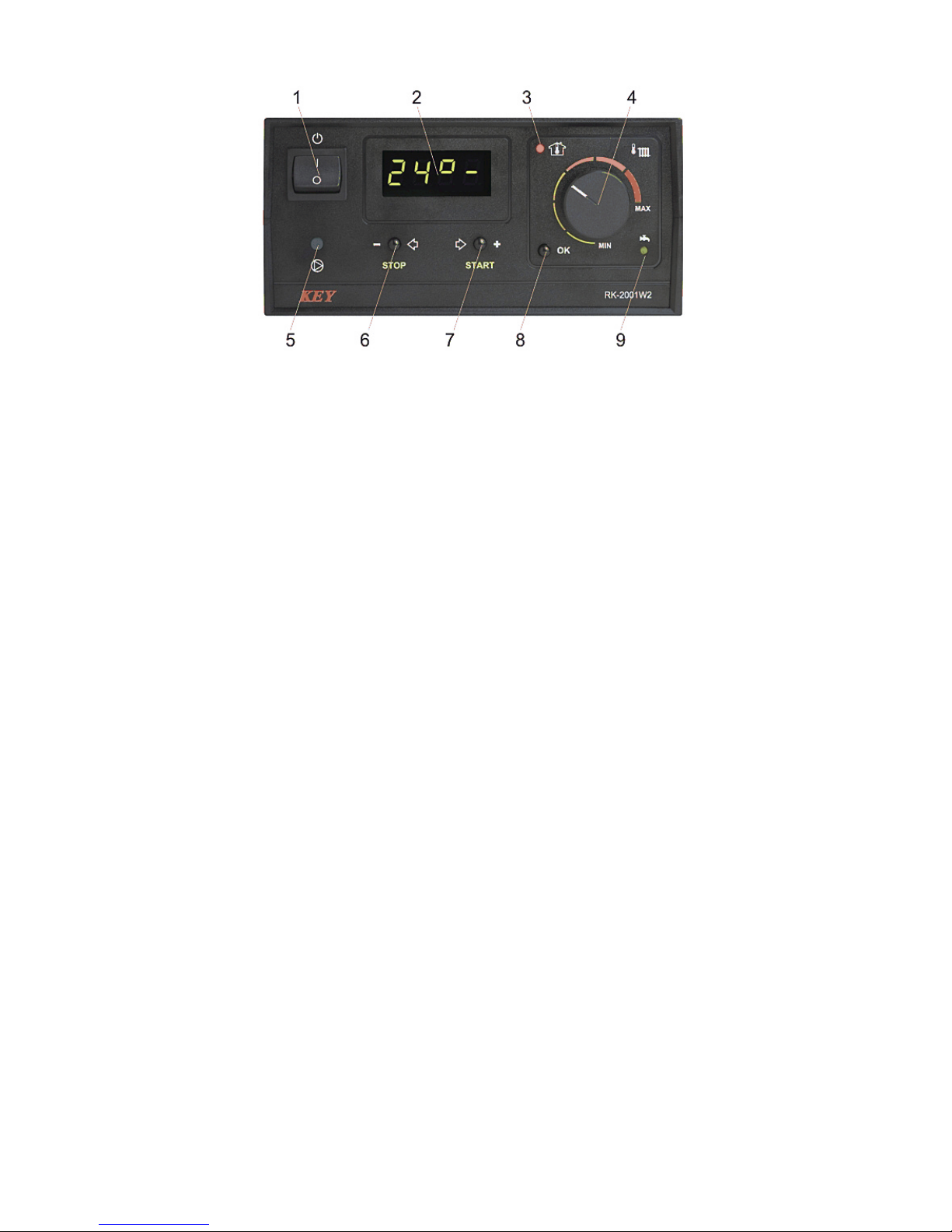
Front plate of the controller (picture 1) consists of:
1 - Master switch
2 - Display, indicating boiler temperature and parameters
3 - Room thermostat indicator
4 - Boiler thermostat knob
5 - Central heating pump indicator
6 - STOP/choose parameters/erase alarms button
7 - START/choose parameters button
8 - Start programming /confirm parameters settings button
9 - Hot water pump work indicator
Page 4
4
Picture 1. Front plate of the RK-2001W2 controller
Basic operation of the controller is carried out by setting the desired temperature with
boiler thermostat knob, other functions are carried out according to parameters
programmed in service mode. The change in the boiler temperature setting is
displayed on the display for a few seconds, e.g. [C 80] and this value means the
temperature of the water in the boiler which the controller will be trying to achieve. You
can also check this value by pressing OK button for a short time. After pressing
START button the fan starts to work and the control process begins. STOP button
stops the fan for example to add fuel.
If the controller is not in user or service mode the display shows water temperature in
the boiler and the last character on the display defines the mode which the controller is
currently in:
for example: [50º-] - STOP mode
[50ºC] - WORK mode
[50ºc] - hold up of burning in WORK mode
[50ºU] – heating of hot water in SUMMER mode
[70ºd] – total bacteria control – heating up of hot water
up to 75ºC.
4. Setting up the user parameters.
Holding OK button enters the user mode and allows to review and is indicated by fast
flashing of the room thermostat indicator. You can look through the parameters with <
and > arrow buttons. After choosing the desired parameter you can switch to the
change mode of the parameter by pressing OK button - it is indicated by the value of
the parameter flashing. Change of the parameter is done by pressing - or + buttons.
You can confirm new settings by pressing OK button and after that the controller
allows to choose another parameter (with < > buttons). If you do not want to change
the parameter value with the < or > button choose [End] and press OK or wait for 1
minute – the controller will exit the service mode and will indicate the temperature of
the water in the boiler.
CAUTION: If in the controller the hot water pump is turned off in the user menu. After
pressing OK, you can only read the set temperature value of the boiler thermostat.
Page 5

5
Table 1. User parameters list.
Disp. Parameter Min Max Step Factory
default
C 45 Boiler desired temperature. L 45 H 85 1°C L 45
co C Central heating pump work when „C” (pump off when „-”). - C C
cu u Heating up „d” - total bacteria control in hot water tank. u d u
50°C Water temperature in hot water tank.
End Exit from user mode.
4.1. Boiler water temperature.
The desired boiler temperature [C 45] – is the temperature which the controller will
try to achieve in WORK mode. It is set by direct turning of the knob and is indicated by
a short display.
4.2. Central heating pump work [co C] – WINTER/SUMMER mode – character „C”
indicates that the central heating pump is working. In summer time the heating can be
turned off by choosing the value “-“ with the (-) button which means turning off the
central heating pump.
4.3. Total bacteria control in the hot water tank [cu u] – heating up - the controller
allows to manually launch the total bacteria control process in which the boiler reaches
the temperature of 75°C in the hot water tank. In order to start the total bacteria control
process the boiler should be in WORK mode (this mode can be turned on by START
button). E.g. [70°d] will appear on the display. After reaching 75°C in the hot water
tank the controller will return to its state before choosing this option.
CAUTION: the total bacteria control function can switched on at night when the water
from the hot water tank is not used to prevent the users from burn injury.
4.4. Water temperature readout in hot water tank [ 50°] – this parameter shows the
measured temperature value in the hot water tank.
4.5. Exit from user mode – choosing the [End] on the display and pressing OK
button causes exit from the parameter setting. Exit from this mode will also occur if no
button is pressed for 1 minute.
5. Parameter setting – the service mode.
Holding OK button for more than 3 seconds enters the service mode where you can
review and change the parameters. It is indicated by flashing of the room thermostat
indicator. You can look through parameters with < and > arrow buttons. After choosing
the desired parameter (indicated by value of the parameter flashing slowly) you can
change the parameter value directly by turning the knob. The change of the value is
indicated by this value flashing. The change of the value will occur after pressing
– or + button. Pressing OK button will confirm the changes. After that the controller
allows to choose another parameter with < > buttons. If you do not want to change the
Page 6

6
parameter value with the < or > button we choose [End] and pres OK or wait for 1
minute – the controller will exit the service mode and will start indicating the
temperature of the water in the boiler.
Table 2. Service parameters list.
Disp. Parameter Min Max Step
Factory
default
Π100 Fan max work power or max power when Πr 0-10. 50 100 10% 100
n 40 Minimum fan power. 20 40 10% 40
Πh 2 Fan speed decrease coefficient. 2 10 1 2
Πr 0 Automatic fan speed control and time of fan start. --, 0 10 1 0
Πn15 Fan work time. --, 5 60 1s 15
Πu 6 Fan pause time. 1 99 1min 6
r 50 Maximum fan speed during boiler start. 50 100 10% 50
rh 5 Boiler start completed hystaresis. 1 45 1ºC 5
P 40 Central heating pump launch temperature. 30 70 1ºC 40
Ph 2 Central heating pump hysteresis. 1 10 1ºC 2
Pc 2 The work mode and pause time of CH pump. --, 1 99, F 1min 2
u 50 Tap hot water desired temperature. 30 60 1ºC 50
uh 5 Hot water heating hysteresis. 1 9 1ºC 5
ur 0
Work mode of hot water pump:
0 - no hot water,
1 - hot water priority,
2 - no hot water priority,
3 - mixing pump.
0 3 1 0
L 45 Minimum boiler temperature. 30 65 1ºC 45
H 85 Maximum boiler temperature. 80 90 1ºC 85
h 2 Boiler temperature hysteresis. 1 10 1ºC 2
A 99 Boiler overheating temperature. 90 99 1ºC 99
Fd2h Fuel shortage testing time with burning. --, 1 99, 4h 1min 2h
Fb2h
Fuel shortage testing time in WORK mode and
burning out.
--, 1 99, 4h 1min 2h
Ar 0
Work mode of extra output:
0- output turning on extra boiler,
1- alarm output,
2- output controlling mixing valve,
3- output controlling emergency cooling system,
4- output controlling extra devices turning on during
work of blow-in fan.
0 4 1 0
Prod Return to factory defaults.
outP Central heating pump testing. outP out1
outΠ Fan output testing. outΠ out2
outr Additional output testing. outr out3
outu Hot water pump output testing. outu out4
End Exit the service mode.
In the table above, the first column represents example display indications, in the next
columns there are: parameter description, minimal amount, maximum amount allowed
to set, step of the parameter during the setup. The last column shows factory defaults
to which you can return by choosing [Prod] option.
Page 7

7
5.1. Fan work parameters.
Fan power [Π100] - this value defines power of the fan. When „Π” parameter is set to
„0-10” this is the maximum power of the fan which can be achieved during automatic
fan control.
Minimum fan power [n 40] - lowest fan power which can be used when automatic
fan speed control is on and when fan speed is gradually increased during boiler start.
Fan speed decrease coefficient [Πh 2] - this parameter influences the way fan
speed is reduced when boiler tremperature is approaching its desired value. E.g.
setting this parameter to 2 means that when the controller is in WORK mode and
boiler temperature is 2°C lower than desired boiler temperature the fan will work with
its maximum power [Π100]. Further increase of boiler temperature will cause fan
speed to be reduced gradually to its minimum power [n 40].
Automatic fan speed control [Πr 0] - it is on, when this parameter is set to „0-10”
and causes automatic fan speed decrease when temperature of water in the boiler
reaches desired temperature. If this parameter is set to „-”, the fan automatic smooth
speed control is disabled and the fan can work with power set by „Π” parameter. When
this parameter is set to a value between 0 and 10 it defines time (in minutes) of
gradual increase of fan speed from its minimum value [n 40] to value [r 50] for smooth
start.
Fan work time [Πn15] - time of turning the fan on for a while, to remove accumulated
gases. Setting the parameter to „--” turns this function off. This function can be active
in WORK mode.
Fan pause time [Nu 6] - time between fan work periods.
Maximum fan speed during boiler start [r 50] - this parameter sets maximum fan
power used during boiler start. If parameter [Πr 0] is set to „0", then this parameter
sets the fan power used during boiler start.
Boiler start completed hysteresis [rh 5] - this parameter defines, how many degrees
before reaching desired temperature boiler start phase is considered to be finished.
Finishing start mode causes the controller to enter work mode.
5.2. Central heating pump parameters.
Central heating pump launch temperature [P 40] – the value of temperature of the
water in the boiler which causes start of the central heating pump. Central heating
pump works independently from the control process and is launched additionally in
case of boiler overheat.
Central heating pump launch hysteresis [Ph 2]- this parameter defines what value
should temperature decrease by, below central heating pump launch temperature so
that the pump turns off.
Page 8

8
The work mode and pause time of CH pump [Pc 2] - in STOP mode or when the
room thermostat circuit is not shorted, CO pump is turned on for 30 seconds to move
water in the heating system. This parameter controls the repeat time. Setting this
parameter to „--” turns this function off. In case of some heating systems the pump
should work independently of room thermostat. In such case the parameter should be
set to value „F”.
5.3. Preparation of hot tap water
The hot water tank temperature [u 50] – temperature value which will be kept in the
hot water tank.
The heating hysteresis of the hot water tank [uh 5] – valve which the temperature
in the tank has to decrease by so that the hot water pump turnes on in order to heat up
the water in the tank.
Work mode of hot water pum [ur 0]
the [ur 0] value indicates no sensor or hot water pump. The sensor is not taken
into account in testing failures, i.e. it can remain unconnected and in the user
parameter menu there is only the desired boiler thermostat temperature
displayed.
[ur 1] value - hot water pump working with priority
[ur 2] value - hot water tank working without priority
[ur 3] value - means controlling of the returning water mixing pump in the
boiler with the launch temperature of [u 50] and hysteresis [uh 5].
5.4. Boiler work temperature setting.
Minimum boiler temperature [L 45] - minimum temperature which you can set with
the boiler thermostat knob.
Maximum boiler temperature [H 85] - maximum temperature which you can set with
the boiler thermostat knob.
Boiler temperature hysteresis [h 2] - this parameter defines what value should
temperature of water in the boiler decrease by, below temperature set with the
thermostat knob so that the fan turns on.
5.5. Boiler overheating protection.
Boiler overheating temperature [A 99] - value, exceeding which causes permanent
turn off of the fan to prevent boiler overheating. After the temperature increases above
80°C the central heating pump is turned on to cool down the boiler. Overheating mode
is indicated by displaying error [E 2] on the display. It can be turned off by pressing
STOP button, but only when temperature decreases below this temperature. Fan turn
off also occurs in case of damage of the boiler temperature sensor which is displayed
on the display with error [E 1].
Page 9

9
STB - the controller has additional protection from overheating which is independent
from the processor. In case the temperature increases over 95°C, the control process
is turned off by turning the fan off and launching the central heating pump. The fan and
the pump are turned on to the control process again when temperature drops below
89°C. STB circuit enables more precise boiler work control and reduces overheating
possibility.
5.6. No fuel.
No-fuel testing time during fuel firing start [Fd2h] - after switching to WORK mode,
if water temperature does not increase by 2°C in programmed time, the control
process will be turned off and the display will show the message: [FUEL]. You can
return to previous mode by pressing STOP button. No fuel testing time during fuel
firing is finished after the set temperature is achieved.
No-fuel testing time during work mode [Fb2h] - in WORK mode, if temperature of
water in the boiler decreases below temperature set with the thermostat, by hysteresis
value, and does not increase by 2°C in the programmed time, the control process will
be turned off and the display will show the message: [FUEL]. You can cancel the
alarm by pressing STOP button.
5.7. Additional output.
Additional output work mode [Ar 0] - the controller is equipped with a multipurpose
output that can work in one of following modes:
- [Ar 0] mode - output may control oil or gas boiler if such boiler exists in the
heating circuit. After switching the controller on with the main power switch, the
additional boiler is turned off and it turnes on again when there is no fuel in the solid
fuel boiler. This function is useful in heating systems where the solid fuel boiler is used
to cut heating costs. After erasing no fuel alarm by pressing STOP button, the
additional boiler is again turned off and the controller works again.
- [Ar 1] mode - output may control additional alarm signaling system. Boiler
temperature sensor malfunction, overheating or no fuel alarm will turn on the
additional alarm.
- [Ar 2] mode - output may control mixing valve servo-motor. Controlling the
mixing valve requires room thermostat to be connected to the controller. The mixing
valve is being opened and closed depending on the room thermostat input.
Additionally, mixing valve is opened in case of overheating or boiler temperature
sensor malfunction.
- [Ar 3] mode - output may control boiler emergency cooling system (e.g. pump).
In this mode the additional output is turned on in case of boiler overheating or boiler
temperature sensor error alarm.
Page 10

10
- [Ar 4] mode - output may control devices working together with blow-in fan.
CAUTION. Equipment should be connected to additional output using UM-1 module.
Connection schemes are shown on picture 3.
5.8. Factory defaults.
Return to standard settings set by the producer by choosing [Prod] and pressing OK
button. After activating this function, the controller sets each parameter showed in the
table 2.
5.9. Testing outputs.
To make checking the controller work easier, it is possible to test output circuits which
control the fan and the pump, and the circuit which controls additional equipment. This
function is available in service mode, only if the control process is off, i.e. the controller
was in STOP mode before switching to service mode. By choosing [outP] on the
display and pressing OK button you can turn on the central heating pump for a while,
by choosing [outΠ] and pressing OK you can turn on the pressure fan and by
choosing [outr] and pressing OK you can turn the additional equipment on (if the
additional module is connected). Choosing [outu] allows testing the hot water pump
output.
5.10. Exiting service mode.
By choosing [End ] option on the display and pressing OK button you can quit
parameter setting mode. The controller also quits service mode, when no buttons are
pressed for 1 minute.
6. Additional functions.
To improve comfort in heated rooms, the controller has been equipped with an input
allowing to connect any kind of room thermostat with contact output. When
temperature in the room is below desired temperature, the central heating pump is
turned on and the room thermostat indicator is lit. It means that the boiler should keep
temperature set by the room thermostat knob. After reaching desired temperature in
the room, the room thermostat indicator turns off, the central heating pump is turned
off and the boiler switches to mode in which it keeps burning at minimum temperature.
CAUTION. In case of not having room thermostat in the system, the room thermostat
input contacts must be short-circuited.
7. Controller failures.
The controller is constantly testing if its internal circuits and temperature sensor are
working correctly. After detection of fault, it stops the fan, turns on the central heating
pump and shows proper error message on the display. In case of failure please turn
off the controller, plug the central heating pump to the power source, ensure
appropriate fuel firing in the boiler and contact the service.
When [E 1] error appears on the display, it means fault in the boiler sensor circuit or
temperature below -9°C. [E 2] is displayed if boiler overheats. [E 3] error means fault
and overheating at the same time. Appearing of [E 1] error on the display without
Page 11

11
ability to cancel it by pressing STOP button, in spite of temperature below 90°C, may
mean permanent damage of boiler temperature sensor (e.g. if the boiler overheated
above 150°C).
In case of programming the sensor and central heating pump in the service mode the
controller tests the hot water sensor circuit. Appearing of fault [E 8] means damage or
lack of hot water sensor.
8 Controller removal.
In case the removal is necessary proceed as follows:
- turn the master switch off
- disconnect the power of the boiler
- remove the controller from the slot in the boiler
- disconnect all connectors with leads from the controller
9 Specifications.
Voltage: 230V ± 10%, 50Hz
Power consumption: <4VA
Temperature measurement range: -9–109°C ± 1°C
Boiler temperature adjustment range: 30–90°C ± 1°C
Programmed boiler overheating protection: 90–99°C ± 1°C
Hardware boiler overheating protection (STB): >95°C ± 1°C
Central heating pump launch temperature: 30–70°C ± 1°C
Hot water pump launch temperature: 30–60°C ± 1°C
Total fan-out: total max 2A/230V
Dimensions (HxWxD) 80x170x100
Page 12

12
Picture 2. RK-2001W2 connection diagram.
Picture 3. UM-1 module connection diagram.
Page 13

13
10 Notes.
Disp. Parameter User
Π100 Fan max work power or max power when Πr 0-10.
n 40 Minimum fan power.
Πh 2 Fan speed decrease coefficient.
Πr 0 Automatic fan speed control and time of fan start.
Πn15 Fan work time.
Πu 6 Fan pause time.
r 50 Maximum fan speed during boiler start.
rh 5 Boiler start completed hystaresis.
P 40 Central heating pump launch temperature.
Ph 2 Central heating pump hysteresis.
Pc 2 The work mode and pause time of CH pump.
u 50 Tap hot water desired temperature.
uh 5 Hot water heating hysteresis.
ur 0
Work mode of hot water pump:
0 - no hot water,
1 - hot water priority,
2 - no hot water priority,
3 - mixing pump.
L 45 Minimum boiler temperature.
H 85 Maximum boiler temperature.
h 2 Boiler temperature hysteresis.
A 99 Boiler overheating temperature.
Fd2h Fuel shortage testing time with burning.
Fb2h Fuel shortage testing time in WORK mode and burning out.
Ar 0
Work mode of extra output:
0- output turning on extra boiler,
1- alarm output,
2- output controlling mixing valve,
3- output controlling emergency cooling system,
4- output controlling extra devices turning on during work of blow-in
fan.
Page 14

14
Page 15

Page 16

Producer: P.W. KEY
11-200 Bartoszyce, ul. Bohaterów Warszawy 67
tel. (89) 763 50 50, fax. (89) 763 50 51
www.pwkey.pl e-mail:pwkey@onet.pl
 Loading...