

Motoriduttore per cancelli a battente
Gear motor for hinged gates
Motoréducteur pour portails à battants
Motorreductor para cancelas batientes
Antriebe für Drehtore
Motorredutores para portões de batente
Motoreduktor do bram skrzydłowych
RÉVO
Istruzioni ed avvertenze per l’installazione e l’uso
Instructions and warnings for installation and use
Instrucciones y advertencias para su instalación y uso
Anleitungen und Hinweise zu Installation und Einsatz
Instruções e advertências para a instalação e utilização
Instructions et avertissements pour l’installation et l’usage
Management
System
ISO 9001:2008
www.tuv.com
ID 9105043769

8
EN
1
2
3
4
5
6
8
Safety warnings
2.1
2.2
4.1
4.2
4.3
4.4
4.5
5.1
5.2
Product overview
Product description
Models and characteristics
Preliminary checks
Installing the product
Installation
Adjusting the mechanical limit switch in
opening
Electrical connections
Mechanical and electronic connections of the
second motor
Replacing led
Testing and commissioning
Testing
Commissioning
Instructions and warnings for the end
user
EC Declaration of Conformity
p. 9
p. 10
p. 10
p. 10
p. 10
p. 11
p. 11
p. 11
p. 11
p. 11
p. 11
p. 12
p. 12
p. 12
p. 13
p. 51
INDEX
7
Figures p. 44

9
EN
1 - SAFETY WARNINGS
CAUTION – ORIGINAL INSTRUCTIONS - important safety instructions. Compliance with the safety instructions below is
important for personal safety. Save these instructions.
Read the instructions carefully before proceeding with installation.
The design and manufacture of the devices making up the
product and the information in this manual are compliant with
current safety standards. However, incorrect installation or
programming may cause serious injury to those working on or
using the system. Compliance with the instructions provided
here when installing the product is therefore extremely impor-
tant.
If in any doubt regarding installation, do not proceed and contact the
Key Automation Technical Service for clarications.
Under European legislation, an automatic door or gate system
must comply with the standards envisaged in the Directive
2006/42/EC (Machinery Directive) and in particular standards
EN 12445; EN 12453; EN 12635 and EN 13241-1, which enable
declaration of presumed conformity of the automation system.
Therefore, nal connection of the automation system to the electrical mains, system testing, commissioning and routine maintenance
must be performed by skilled, qualied personnel, in observance of
the instructions in the “Testing and commissioning the automation
system” section.
The aforesaid personnel are also responsible for the tests required
to verify the solutions adopted according to the risks present, and
for ensuring observance of all legal provisions, standards and regulations, with particular reference to all requirements of the EN 12445
standard which establishes the test methods for testing door and
gate automation systems.
WARNING - Before starting installation, perform the following
checks and assessments:
ensure that every device used to set up the automation system is
suited to the intended system overall. For this purpose, pay special
attention to the data provided in the “Technical specications” section. Do not proceed with installation if any one of these devices is
not suitable for its intended purpose;
check that the devices purchased are sufcient to guarantee system
safety and functionality;
perform a risk assessment, including a list of the essential safety
requirements as envisaged in Annex I of the Machinery Directive,
specifying the solutions adopted. The risk assessment is one of the
documents included in the automation system’s technical le. This
must be compiled by a professional installer.
Considering the risk situations that may arise during installation phases and use of the product, the automation system
must be installed in compliance with the following safety precautions:
never make modications to any part of the automation system
other than those specied in this manual. Operations of this type
can only lead to malfunctions. The manufacturer declines all liability
for damage caused by unauthorised modications to products;
if the power cable is damaged, it must be replaced by the manufacturer or its after-sales service, or in all cases by a person with similar
qualications, to prevent all risks;
do not allow parts of the automation system to be immersed in water
or other liquids. During installation ensure that no liquids are able to
enter the various devices;
should this occur, disconnect the power supply immediately and
contact a Key Automation Service Centre. Use of the automation
system in these conditions may cause hazards;
never place automation system components near to sources of heat
or expose them to naked lights. This may damage system components and cause malfunctions, re or hazards;
all operations requiring opening of the protective housings of various automation system components must be performed with the
control unit disconnected from the power supply. If the disconnect
device is not in a visible location, afx a notice stating: “MAINTENANCE IN PROGRESS”:
connect all devices to an electric power line equipped with an
earthing system;
the product cannot be considered to provide effective protection
against intrusion. If effective protection is required, the automation
system must be combined with other devices;
the product may not be used until the automation system “commissioning” procedure has been performed as specied in the “Automation system testing and commissioning” section;
the system power supply line must include a circuit breaker device
with a contact gap allowing complete disconnection in the conditions specied by class III overvoltage;
use unions with IP55 or higher protection when connecting hoses,
pipes or cable glands;
the electrical system upstream of the automation system must comply with the relevant regulations and be constructed to good workmanship standards;
users are advised to install an emergency stop button close to the
automation system (connected to the control PCB STOP input) to
allow the door to be stopped immediately in case of danger;
this device is not intended for use by persons (including children)
with impaired physical, sensory or mental capacities, or with lack
of experience or skill, unless a person responsible for their safety
provides surveillance or instruction in use of the device;
before starting the automation system, ensure that there is no-one
in the immediate vicinity;
before proceeding with any cleaning or maintenance work on the
automation system, disconnect it from the electrical mains;
special care must be taken to avoid crushing between the part operated by the automation system and any xed parts around it;
children must be supervised to ensure that they do not play with the
equipment.
WARNING - The automation system component packaging material must be disposed of in full observance of current local
waste disposal legislation.
WARNING - The data and information in this manual are subject
to modication at any time, with no obligation on the part of
Key Automation S.r.l. to provide notice.
10
EN
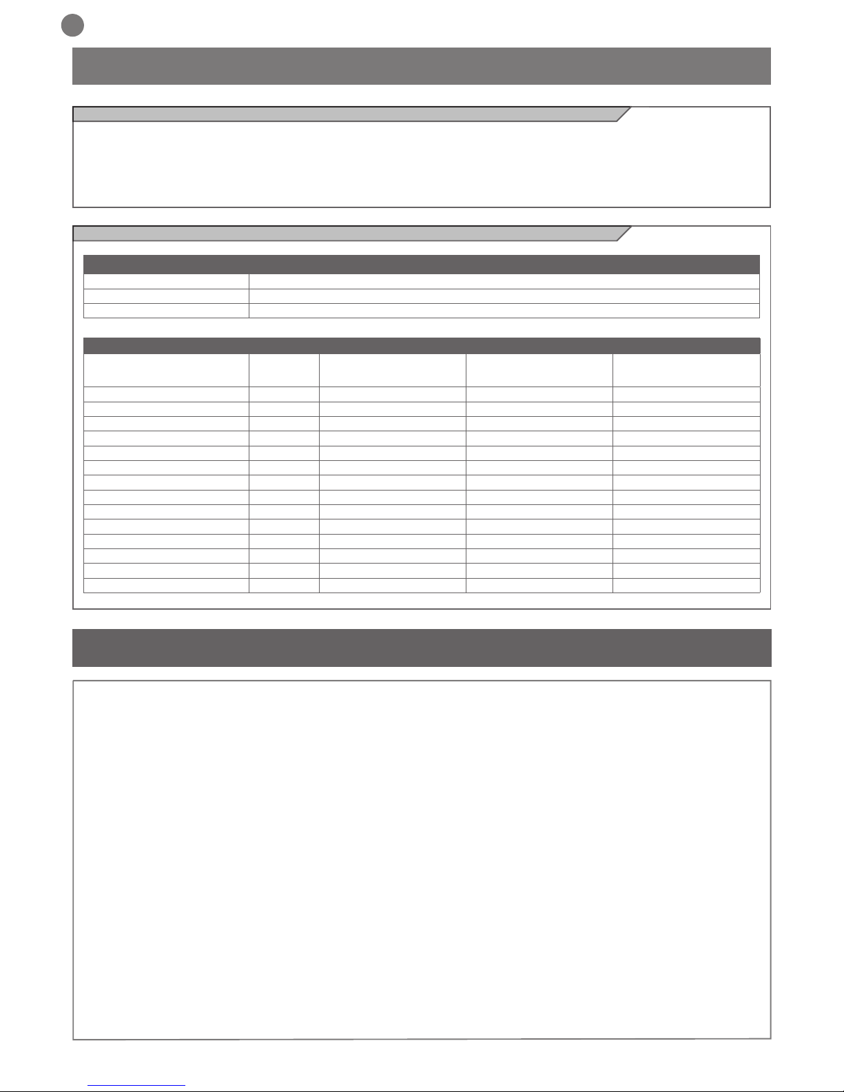
Code Description
REVO2024 24 Vdc gear motor for hinged doors with max length 2,3 m or weight 250 Kg, 230 Vac
REVO2024S 24 Vdc gear motor for hinged doors with max length 2,3 m or weight 250 Kg, without control unit
REVO20110 24 Vdc gear motor for hinged doors with max length 2,3 m or weight 250 Kg, 110 Vac
TECHNICAL DATA
MODELS REVO2024 REVO2024S REVO20110
TECHNICAL SPECIFICATIONS
Torque Nm 120 120 120
Working cycle % 80 80 80
Opening time at 90° sec adjustable adjustable adjustable
Control board 14A - 14A
Power supply Vac (Vdc) 230 (24) (24) 110 (24)
Absorption A 0,5 2 1
Engine power W 100 50 100
Integrated lights yes yes yes
Degree of protection IP 44 44 44
Dimensions (L - P - H) mm 120 - 250 - 350 120 - 250 - 350 120 - 250 - 350
Weight Kg 10,5 8 10,5
Operating temperature °C -20°+55° -20°+55° -20°+55°
Leaves maximum weight Kg 250 250 250
2 - PRODUCT OVERVIEW
2.1 - Description of the product
The RÉVO gear motors are destined to be installed in systems for the
automation of gates with hinged doors.
The RÉVO gear motors have been designed and constructed to be
tted onto hinged doors within the weight limits indicated in the
technical specications table.
The use of gear motors for applications which differ from those
indicated above is prohibited.
2.2 - Model and technical characteristics
3 - PRELIMINARY CHECKS
Before installing this product, verify and check the following steps:
- Check that the gate or door are suitable for automation
- The weight and size of the gate or door must be within the maximum permissible operating limits specied in Fig. 2
- Check the presence and strength of the security mechanical stops
of the gate or door
- Check that the mounting area of the product is not subject to ooding
- Conditions of high acidity or salinity or proximity to heat sources
could cause malfunction of the product
- Extreme weather conditions (for example the presence of snow,
ice, high temperature range, high temperatures) may increase the
friction and therefore the force required for the handling and initial
starting point may be higher than under normal conditions.
- Check that the manual operation of gate or door is smooth and
friction-free and there is no risk of derailment of the same
- Check that the gate or door are in equilibrium and stationary if left
in any position
- Check that the power line to supply the product is equipped with
proper grounding safety and protected by a magnetothermal and
differential security device
- Provide the power system with a disconnecting device with a gap
of contacts enabling full disconnection under the conditions dictated
by the overvoltage category III.
- Ensure that all materials used for the installation comply with cur-
rent regulations
11
EN
Unscrew the cover screws (Fig.15a). Raise the back by about 1 cm
then slide it out forwards (Fig.15b).
ATTENTION: the lights on the cover are connected by two
wires, disconnect the terminal or lay carefully the cover
upside-down on the external part (Fig.16).
Loosen the screw of the mechanical limit switches up to when they
can slide (Fig.12).
Release the gearmotor and open manually the leaf up to the
requested opening position.
Insert the pin completely into the rst free hole close to the leaf
(Fig.13).
Move the mechanical stop up to the stop limit on the pin head
(Fig.14a) and screw again the mechanical stop (Fig.14b).
In order to adjust the stop in opening, move the leaf up to the
requested opening position and insert the pin into the rst free
hole opposite to the leaf.
Move the mechanical stop on the stop limit on the pin head (Fig.14a)
and screw it again (Fig.14b).
4.2 - Adjusting the mechanical limit switch in opening
Switch-off the power supply.
Open the cover as shown on paragraph 4.2.
By using a screwdriver, release the bottom screw of the cover
(Fig.19a).
Remove the mask and pull out the led band (Fig.19b) .
In case of installation of the second motor, follow the above
mentioned instructions for the mechanical mounting, for the
Disconnect the plug connector (Fig.20a).
Connect the new led stripe and insert them into the mask.
Insert the mask by placing rst the seal side and then fastening it
with the screw (Fig.20b).
electrical connections refer to the Fig.21.
4.5 - Replacing led
4.4 - Mechanical and electronic connections of the second motor
4.1 - Installation
Before starting the installation, make sure that the product is intact
and that the packaging contains all the components shown in Fig.3.
Make sure that the mounting area is compatible with the overall
dimensions (Fig.1).
Check the allowed opening angle according to the xing points of the
brackets in Fig.4 and in the diagram in Fig.5.
Fig.6 is an example of a typical system:
- Operators (1)
- Photocells (2)
- Posts for photocells (3)
- Flashing light with integrated aerial (4)
- Key or digital switch (5)
Mounting
Measure the value C (Fig. 4) = distance between the rotation fulcrum
of the leaf and the pillar surface where the rear bracket will be xed.
Move manually the leaf up to the opening required (maximum 120°):
establish the value of the maximum opening angle of each leaf.
Mark on the diagram in Fig.5 the value C and trace an horizontal
line up to intersect the area that includes the angle value measured
before.
Trace some vertical lines on the intersection points between the
horizontal line and the area in order to nd the useful values for the
dimension A (g. 4).
Chose the value A in this range.
Mark on the pillar the value A and trace a vertical line in
correspondence (Fig.7a).
Mounting the motor bracket to the pillar
Draw a horizontal line on the pillar in line where the leaf bracket
should be xed (Fig.7b).
Center the pillar bracket with the vertical line and the horizontal line
previously traced by xing the bracket using suitable screws and
washers (not supplied) (Fig.7c).
Fasten the motor to the pillar bracket with the two screws and nuts
supplied (Fig.8).
During this phase, make sure that the motor is perfectly aligned.
ATTENTION: an off-axis mounting can cause malfunctioning
and damage the automation system.
Mounting the motor bracket
Move the gate leaf up to the maximum opening position (Fig.9).
Release the gearmotor (Fig.10)
Place the arm close to the leaf and lay on the leaf the gate bracket;
holding with one hand the bracket in contact with the leaf, try to
make a complete opening and closing movement.
Fasten the gate bracket to the leaf with suited screws (not supplied)
(Fig.11a).
Fasten the motor arm to the bracket, by inserting the pin and the
corresponding safety ring (Fig.11b).
Important: make sure that the bracket and the gate arm are
perfectly aligned.
ATTENTION: a not aligned mounting can cause malfunctioning
and damage the automation system
4.3 - Electrical connections
Insert the supply cable (Fig.17). Connect the wires of the supply
cable to the terminal following the electrical drawing in Fig. 18.
Proceed with the other connections following the control unit’s
instructions.
Replace the cover to its original position and fasten the two xing
screws.
4 - PRODUCT INSTALLATION

12
EN
5.2 Commissioning
Following the successful testing of all (and not just some) devices in
the system you can proceed with the commissioning.
You must prepare, and keep for 10 years, the technical le of the
system with the wiring diagram, drawing or photo of the system,
risks analysis and solutions adopted, manufacturer declaration of
conformity of all devices connected, instruction manual of each device and maintenance schedule of the system.
Fix on the gate or door a plaque indicating the automation data, the
name of the person responsible for the commissioning, the serial
number and year of construction, the CE mark.
Attach a plaque indicating the steps required to manually unlock
the system.
Implement and deliver to the end user the declaration of conformity, the instructions and warnings for use for the end user and the
maintenance schedule of the system.
Make sure the user understands proper automatic, manual and
emergency operation of the automation.
Inform the end user in writing of the dangers and risks still present.
5.1 Testing
All system components must be tested following the procedures
outlined in the respective instruction manuals.
Check that they meet the guidelines in Chapter 1 - Safety warnings
Check that the gate or door can move freely once the automation
is unlocked, and that they are in equilibrium and stationary if left in
any position.
Check the correct operation of all connected devices (photocells,
sensitive edges, emergency buttons, etc.), testing the opening,
closing and stopping of the gate or door via the connected control
devices (transmitters, buttons, switches).
Carry out measurements of the impact force, as prescribed by
standard EN12445 adjusting the functions of speed, motor force
and deceleration of the unit if the measurements do not give the
desired results until you nd the right setting.
The testing of the system must be performed by qualied technicians who must perform the tests required by relevant legislation
related to risks, ensuring compliance with the provisions of the
regulations, in particular the EN12445 standard, which species the
testing methods for the automation of doors and gates.
5- TESTING AND COMMISSIONING THE AUTOMATION

13
EN
Key Automation S.r.l. produces systems for the automation of gates,
garage doors, automatic doors, shutters, parking lots and road barriers. However, Key Automation is not the manufacturer of your automation system, which is rather the result of a process of analysis,
evaluation, selection of materials, and installation performed by
your own installer. Each automated system is unique and only your
installer has the experience and professionalism required to create
a system to suit your needs, safe and reliable over time, and carried
out in a workmanlike manner, i.e. compliant with the current regulations. Even if your automation system meets the security level required by law, this does not exclude the existence of "residual risks",
i.e. the possibility that it may cause dangerous situations, usually as
a result of improper or irresponsible use; for this reason we would
like to give you some suggestions:
• Before using the automation for the rst time, ask the installer to
explain the origin of residual risks.
• Keep this manual for future use and deliver it to any new owner of
the automation.
• Inappropriate or improper use of the automation can make it dangerous: do not command the movement of the automation if people,
animals or things are in its range.
• Children: If properly designed, an automation system ensures a
high degree of security, preventing movement in the presence of
people or things with its detection systems, and ensuring always
predictable and safe activation. It is prudent to prevent children from
playing near the automation and keep remote controls out of their
reach to prevent accidental activation.
• Malfunctions: As soon as you notice any malfunctions, disconnect
the system from the power supply and operate the manual release.
Do not attempt any repairs by yourself, but require the assistance
of your installer: meanwhile, the system can operate like a non-automated opening device after releasing the motor reducer with the
release key supplied with the system.
• In case of failures or power failures: While awaiting the arrival of
your installer or the restore of the electricity, if the system is not
equipped with backup batteries, the automation can be operated as
any normal non-automated opening device. To do this, you must run
the manual release.
Release and manual movement: before performing this operation
pay attention that the device can be released only when the door
is stationary.
• Maintenance: Like any machine, your automation needs periodic
maintenance to ensure its long life and total safety. Agree with your
installer on a maintenance plan on a periodic basis; Key Automation
recommends a frequency of 6 months for normal domestic use, but
this period may vary depending on the intensity of use. All inspection, maintenance or repairs should be performed only by qualied
personnel.
• Do not change the system and control or programming parameters
of the automation: the responsibility lies with your installer.
• The testing, routine maintenance and any repairs must be documented by the person who performs them, and related documents
must kept by the owner.
The only interventions that are possible for the user and should be
carried out periodically are the cleaning of the slides and photocells, as well as the removal of any leaves or rocks that could hinder
the automation. To prevent anyone from activating the gate or door,
before proceeding, remember to release the automation and clean
only with a cloth slightly dampened with water.
• Disposal: At the end of the automation useful life, make sure that
the dismantling is carried out by qualied personnel and the materials are recycled or disposed of according to local regulations in
force.
• Operate the gate or door (with remote control, key switch, etc..);
if everything is working properly, the gate or the door will open and
close normally, otherwise the ashing light ashes and the maneu-
ver does not start.
With the safeties out of use, the automation must be repaired as
soon as possible.
Replacing the remote control battery: if your remote control seems
to work worse or not work at all after a while, this may simply depend on the exhaustion of the battery (depending on use, it may
take several months to over a year). In that case, you will see that
the conrmation of transmission light does not turn on, or comes on
only briey.
The batteries contain polluting substances: do not throw them in the
garbage but use the methods prescribed by local regulations.
Thank you for choosing keyautomation; for more information feel
free to visit our website www.keyautomation.it.
6 - INSTRUCTIONS AND WARNINGS FOR THE END USER

44
Fig. 2 IT - Limiti di impiego
EN - Use limitations
FR - Limites d’utilisation
ES - Límites de uso
DE - Einsatzgrenzen
PT - Limites de uso
PL - Ograniczenia użytkowania
Fig. 3 IT - Componenti
EN - Components
FR - Composants
ES - Componentes
DE - Bauteile
PT - Componentes
PL - Komponenty
Fig. 1 IT - Dimensioni d’ ingombro
EN - Space dimensions
FR - Dimensions d’encombrement
ES - Dimensiones
DE - Abmessungen
PT - Dimensões globais
PL - Wymiary
KG
IT - Peso massimo dell’ anta del cancello
EN - Maximum weight of the gate door
FR - Poids maximum du battant du portail
ES - Peso máximo de la puerta de la cancela
DE - Maximales Gewicht des Torügels
PT - Peso máximo do painel do portão
PL - Waga maksymalna skrzydła bramy
m
IT - Lunghezza massima dell’ anta del cancello
EN - Maximum length of the gate door
FR - Longueur maximum du battant du portail
ES - Longitud máxima de la puerta de la cancela
DE - Maximale Länge des Torügels
PT - Comprimento máximo do painel do portão
PL - Długość maksymalna skrzydła bramy
250
200
150
100
1,7 1,8 1,9 2 2,1 2,2 2,3
IMAGES
MAX DOOR WEIGHT (kg)
MAXIMUM DOOR LENGTH (m)
120
MIN 210
250
350
570
1a 1b
450 MAX 740

45
DE - Darstellung der Werte
PT - Quotas de representação
PL - Przedstawienie wartości
DE - Zeichnung zum Öffnungswinke
PT - Gráco ângulo de abertura
PL - Wykres kąta otwarcia
DE - Typische Installation
PT - Gráco ângulo de abertura
PL - Wykres kąta otwarcia
Fig. 5 IT - Graco angolo di apertura
EN - Opening angle graph
FR - Graphique angle d’ouverture
ES - Gráco ángulo de apertura
Fig. 4 IT - Rappresentazione quote
EN - Quotes representation
FR - Représentation hauteurs
ES - Representación cuotas
Fig. 6 IT - Installazione tipica
EN - Typical Installation
FR - Installation type
ES - Instalación típica
C
A
E
C
A
200
190
180
170
160
150
140
130
120
110
100
90
80
70
60
50
40
30
20
10
0
100 110 120 130 140 150 160 170 180 190 200 210 220 230 240 250 260 270 280 290 300
A
C
90/95°
95/100°
100/105°
105/110°
110/115°
115/120°
120°
1 1
22
3 3
4
5

46
7b 7c7a
Fig. 7 IT - Posizionamento del motoriduttore
EN - Positioning the motor
FR - Positionnement moteur
ES - Colocación del motorreductor
MAX
DE - Positionierung des Antriebs
PT - Posicionamento do motorredutor
PL - Położenie motoreduktora
Fig. 8 IT - Fissaggio motoriduttore
EN - Fixing the motor
FR - Fixation moteur
ES - Fijación del motorreductor
DE - Befestigung des Antriebs
PT - Fixação do motorredutor
PL - Mocowanie motoreduktora
Fig. 9 IT - Fissaggio staffa cancello
EN - Fixing the leaf bracket
FR - Fixation patte portail
ES - Fijación del estribo en la puerta
DE - Befestigung des Torbeschlags
PT - Fixação da placa do portão
PL - Mocowanie obejmy bramy

47
10a
11a
10b
11b
LOCK
UNLOCK
Fig. 10 IT - Sblocco del motoriduttore
EN - Gearmotor release
FR - Déblocage du motoréducteur
ES - Desbloqueo del motorreductor
Fig. 11 IT - Fissaggio staffa cancello
EN - Fixing the leaf bracket
FR - Fixation patte portail
ES - Fijación del estribo en la puerta
Fig. 12 IT - Regolazione dei necorsa meccanici
EN - Mechanical stop adjustment
FR - Réglage des ns de course mécaniques
ES - Regulación de los nales de carrera mecánicos
DE - Entriegeln des Getriebemotors
PT - Desbloqueio do motorredutor
PL - Odblokowanie motoreduktora
DE - Anbringung des Torbeschlags
PT - Fixação da placa do portão
PL - Mocowanie obejmy bramy
DE - Einstellung der mechanischen Endanschläge
PT - Regulação dos ns de curso mecânicos
PL - Regulacja mechanicznych wyłączników krańcowych

48
Fig. 13 IT - Fissaggio vite necorsa
EN - Fixing the stop screw
FR - Fixation vis n de course
ES - Fijación del tornillo del nal de carrera
Fig. 14 IT - Fissaggio necorsa
EN - Fixing limit switch
FR - Fixation n de course
ES - Fijación del nal de carrera
Fig. 15 IT - Connessioni elettriche
EN - Electrical connections
FR - Connexions électriques
ES - Conexiones eléctricas
14a 14b
15a 15b
1 cm
DE - Anziehen der Endanschlagsschraube
PT - Fixação do parafuso de m de curso
PL - Mocowanie śruby wyłącznika krańcowego
DE - Befestigung des Endanschlags
PT - Fixação do m de curso
PL - Mocowanie wyłącznika krańcowego
DE - Elektrische Anschlüsse
PT - Conexões eléctricas
PL - Połączenia elektryczne

49
Fig. 16 IT - Posizione coperchio
EN - Positioning the cover
FR - Position couvercle
ES - Posición de la cubierta
Fig. 17 IT - Passaggio cavo
EN - Cable routing
FR - Passage câble
ES - Paso del cable
Fig. 18 IT - Connessioni e cablaggi
EN - Connections and cables
FR - Connexions et câblages
ES - Conexiones y cableados
DE - Position des Deckels
PT - Posição da tampa
PL - Położenie pokrywy
DE - Kabeldurchführung
PT - Passagem do cabo
PL - Przebieg przewodu elektrycznego
DE - Anschlüsse und Verdrahtung
PT - Ligações e cabos
PL - Podłączenia i okablowanie

50
G
COM
LED
M -
M +
20a 20b
1
2
19a 19b
Fig. 19 IT - Rimozione mascherina
EN - Removing the mask
FR - Retrait masque
ES- Extracción de la tapa
Fig. 20 IT - Sostituzione led
EN - Replacement of the leds
FR - Remplacement des DEL
ES - Sustitución de las luces led
Fig. 21 IT - Collegamento secondo motore
EN - Second motor connections
FR - Connexion deuxième moteur
ES - Conexión del segundo motor
DE - Entfernen der Abdeckung
PT - Retirada da cobertura
PL - Demontaż osłony
DE - Auswechseln der Led
PT - Substituição led
PL - Wymiana diod led
DE - Anschluss des Zweitmotors
PT - Ligação do segundo motor
PL - Podłączenie drugiego silnika

SELF INSTALL - NEED TECHNICAL
ASSISTANCE?
OPTION 1: DIRECT WITH THE SERVICE DESK – QUICKEST AND MOST EFFECTIVE METHOD
Submit your enquiry direct with the service desk at – service@automaticsolutions.com.au
The service desk has the most experienced staff in Australia to help with your problem but they need your help.
Describe your problem in detail and as clearly as possible. Don’t forget to include a telephone number.
Be certain to detail which model or models of you are working with.
Send photos of the installation – they love photos. The people at the service desk are good but they are
even better when they can see the installation. Send photos of the overall scene so they can see the
entire installation. Also send photos of the wiring to the control board and any other part of the
installation you think is relevant.
Send video if appropriate. Smartphone’s these days take remarkably good video in small file sizes which
can be emailed in a moment. If your problem needs a video to show the issue please feel free to send it.
NOTE: THIS IS BY FAR THE FASTEST AND MOST SUCCESFUL WAY TO SOLVE YOUR PROBLEM
PHOTOS AND VIDEOS ARE THE NEXT BEST THING TO BEING THERE
OPTION 2: LODGE YOUR ENQUIRY LOCALLY - SLOWER BUT CAN STILL BE EFFECTIVE
Make contact with the store of purchase. Branch staffs are typically not technicians and dependent on their length
of service will have varying degrees of technical knowledge. If they cannot help however they will certainly either
source help locally from their technicians or make contact with the service technicians on your behalf.
OPTION 3: SERVICE CALL WITH AUTOMATIC SOLUTIONS TECHNICIAN – SLOWEST METHOD
If you fall within the local branch service area it may be possible to book a local technician to look at your
installation. Wait times will vary dependent on local workloads. The cost is a service fee which includes the first
half hour and the hourly rate thereafter. If any Automatic Solutions provided parts are found to be defective and
within warranty these will be provided free of charge.
(NOTE: If you suspect that any parts are defective and within warranty you may wish to consider option 4)
A note on this option: If you decide on this option you will be asked to sign an “authorisation to proceed” which
will provide legal authority and payment security. This form has three options available of which only the first two
are available to you. The third option is for warranty repairs only for full install customers. Self install customers
requiring warranty only service need to refer to option four below.
IMPORTANT: IN SHORT THIS OPTION WILL INCUR CHARGES
OPTION 4: RETURN THE PRODUCT IF BELIEVED TO BE FAULTY
As a self install customer who has purchased product if you believe the product to be faulty rather than an
installation or site problem you have the option of returning the product for evaluation and to exercise your right
to a replacement, repair or refund as applicable. All returned product is forwarded immediately to the service
technicians for evaluation and response. There are two main methods available to return product –
Direct to the service centre – this is the quickest method as it cuts out the branch delay
Via the branch of purchase – slower because of the delay at the branch
When choosing this option you need to complete a product return form. This form gives you all the information
on procedure involved and where to send to. These are available at the branch of purchase, can be emailed to
you (contact your branch), or available here - http://automaticsolutions.com.au/page/warranty.php
 Loading...